EP1482138A1 - Exhaust emission control system, method of calculating pressure loss of filter, and method of manufacturing filter - Google Patents
Exhaust emission control system, method of calculating pressure loss of filter, and method of manufacturing filter Download PDFInfo
- Publication number
- EP1482138A1 EP1482138A1 EP03743537A EP03743537A EP1482138A1 EP 1482138 A1 EP1482138 A1 EP 1482138A1 EP 03743537 A EP03743537 A EP 03743537A EP 03743537 A EP03743537 A EP 03743537A EP 1482138 A1 EP1482138 A1 EP 1482138A1
- Authority
- EP
- European Patent Office
- Prior art keywords
- filter
- pressure loss
- control system
- emission control
- face
- Prior art date
- Legal status (The legal status is an assumption and is not a legal conclusion. Google has not performed a legal analysis and makes no representation as to the accuracy of the status listed.)
- Withdrawn
Links
Images



Classifications
-
- B—PERFORMING OPERATIONS; TRANSPORTING
- B01—PHYSICAL OR CHEMICAL PROCESSES OR APPARATUS IN GENERAL
- B01D—SEPARATION
- B01D46/00—Filters or filtering processes specially modified for separating dispersed particles from gases or vapours
- B01D46/24—Particle separators, e.g. dust precipitators, using rigid hollow filter bodies
- B01D46/2403—Particle separators, e.g. dust precipitators, using rigid hollow filter bodies characterised by the physical shape or structure of the filtering element
- B01D46/2418—Honeycomb filters
- B01D46/2451—Honeycomb filters characterized by the geometrical structure, shape, pattern or configuration or parameters related to the geometry of the structure
- B01D46/2474—Honeycomb filters characterized by the geometrical structure, shape, pattern or configuration or parameters related to the geometry of the structure of the walls along the length of the honeycomb
-
- F—MECHANICAL ENGINEERING; LIGHTING; HEATING; WEAPONS; BLASTING
- F01—MACHINES OR ENGINES IN GENERAL; ENGINE PLANTS IN GENERAL; STEAM ENGINES
- F01N—GAS-FLOW SILENCERS OR EXHAUST APPARATUS FOR MACHINES OR ENGINES IN GENERAL; GAS-FLOW SILENCERS OR EXHAUST APPARATUS FOR INTERNAL-COMBUSTION ENGINES
- F01N3/00—Exhaust or silencing apparatus having means for purifying, rendering innocuous, or otherwise treating exhaust
- F01N3/02—Exhaust or silencing apparatus having means for purifying, rendering innocuous, or otherwise treating exhaust for cooling, or for removing solid constituents of, exhaust
-
- B—PERFORMING OPERATIONS; TRANSPORTING
- B01—PHYSICAL OR CHEMICAL PROCESSES OR APPARATUS IN GENERAL
- B01D—SEPARATION
- B01D46/00—Filters or filtering processes specially modified for separating dispersed particles from gases or vapours
- B01D46/24—Particle separators, e.g. dust precipitators, using rigid hollow filter bodies
- B01D46/2403—Particle separators, e.g. dust precipitators, using rigid hollow filter bodies characterised by the physical shape or structure of the filtering element
- B01D46/2418—Honeycomb filters
- B01D46/2451—Honeycomb filters characterized by the geometrical structure, shape, pattern or configuration or parameters related to the geometry of the structure
- B01D46/2482—Thickness, height, width, length or diameter
-
- B—PERFORMING OPERATIONS; TRANSPORTING
- B01—PHYSICAL OR CHEMICAL PROCESSES OR APPARATUS IN GENERAL
- B01D—SEPARATION
- B01D46/00—Filters or filtering processes specially modified for separating dispersed particles from gases or vapours
- B01D46/24—Particle separators, e.g. dust precipitators, using rigid hollow filter bodies
- B01D46/2403—Particle separators, e.g. dust precipitators, using rigid hollow filter bodies characterised by the physical shape or structure of the filtering element
- B01D46/2418—Honeycomb filters
- B01D46/2498—The honeycomb filter being defined by mathematical relationships
-
- F—MECHANICAL ENGINEERING; LIGHTING; HEATING; WEAPONS; BLASTING
- F01—MACHINES OR ENGINES IN GENERAL; ENGINE PLANTS IN GENERAL; STEAM ENGINES
- F01N—GAS-FLOW SILENCERS OR EXHAUST APPARATUS FOR MACHINES OR ENGINES IN GENERAL; GAS-FLOW SILENCERS OR EXHAUST APPARATUS FOR INTERNAL-COMBUSTION ENGINES
- F01N11/00—Monitoring or diagnostic devices for exhaust-gas treatment apparatus
- F01N11/002—Monitoring or diagnostic devices for exhaust-gas treatment apparatus the diagnostic devices measuring or estimating temperature or pressure in, or downstream of the exhaust apparatus
- F01N11/005—Monitoring or diagnostic devices for exhaust-gas treatment apparatus the diagnostic devices measuring or estimating temperature or pressure in, or downstream of the exhaust apparatus the temperature or pressure being estimated, e.g. by means of a theoretical model
-
- F—MECHANICAL ENGINEERING; LIGHTING; HEATING; WEAPONS; BLASTING
- F01—MACHINES OR ENGINES IN GENERAL; ENGINE PLANTS IN GENERAL; STEAM ENGINES
- F01N—GAS-FLOW SILENCERS OR EXHAUST APPARATUS FOR MACHINES OR ENGINES IN GENERAL; GAS-FLOW SILENCERS OR EXHAUST APPARATUS FOR INTERNAL-COMBUSTION ENGINES
- F01N13/00—Exhaust or silencing apparatus characterised by constructional features
- F01N13/009—Exhaust or silencing apparatus characterised by constructional features having two or more separate purifying devices arranged in series
-
- F—MECHANICAL ENGINEERING; LIGHTING; HEATING; WEAPONS; BLASTING
- F01—MACHINES OR ENGINES IN GENERAL; ENGINE PLANTS IN GENERAL; STEAM ENGINES
- F01N—GAS-FLOW SILENCERS OR EXHAUST APPARATUS FOR MACHINES OR ENGINES IN GENERAL; GAS-FLOW SILENCERS OR EXHAUST APPARATUS FOR INTERNAL-COMBUSTION ENGINES
- F01N13/00—Exhaust or silencing apparatus characterised by constructional features
- F01N13/011—Exhaust or silencing apparatus characterised by constructional features having two or more purifying devices arranged in parallel
- F01N13/017—Exhaust or silencing apparatus characterised by constructional features having two or more purifying devices arranged in parallel the purifying devices are arranged in a single housing
-
- F—MECHANICAL ENGINEERING; LIGHTING; HEATING; WEAPONS; BLASTING
- F01—MACHINES OR ENGINES IN GENERAL; ENGINE PLANTS IN GENERAL; STEAM ENGINES
- F01N—GAS-FLOW SILENCERS OR EXHAUST APPARATUS FOR MACHINES OR ENGINES IN GENERAL; GAS-FLOW SILENCERS OR EXHAUST APPARATUS FOR INTERNAL-COMBUSTION ENGINES
- F01N3/00—Exhaust or silencing apparatus having means for purifying, rendering innocuous, or otherwise treating exhaust
- F01N3/02—Exhaust or silencing apparatus having means for purifying, rendering innocuous, or otherwise treating exhaust for cooling, or for removing solid constituents of, exhaust
- F01N3/021—Exhaust or silencing apparatus having means for purifying, rendering innocuous, or otherwise treating exhaust for cooling, or for removing solid constituents of, exhaust by means of filters
- F01N3/022—Exhaust or silencing apparatus having means for purifying, rendering innocuous, or otherwise treating exhaust for cooling, or for removing solid constituents of, exhaust by means of filters characterised by specially adapted filtering structure, e.g. honeycomb, mesh or fibrous
- F01N3/0222—Exhaust or silencing apparatus having means for purifying, rendering innocuous, or otherwise treating exhaust for cooling, or for removing solid constituents of, exhaust by means of filters characterised by specially adapted filtering structure, e.g. honeycomb, mesh or fibrous the structure being monolithic, e.g. honeycombs
-
- F—MECHANICAL ENGINEERING; LIGHTING; HEATING; WEAPONS; BLASTING
- F01—MACHINES OR ENGINES IN GENERAL; ENGINE PLANTS IN GENERAL; STEAM ENGINES
- F01N—GAS-FLOW SILENCERS OR EXHAUST APPARATUS FOR MACHINES OR ENGINES IN GENERAL; GAS-FLOW SILENCERS OR EXHAUST APPARATUS FOR INTERNAL-COMBUSTION ENGINES
- F01N9/00—Electrical control of exhaust gas treating apparatus
- F01N9/002—Electrical control of exhaust gas treating apparatus of filter regeneration
-
- B—PERFORMING OPERATIONS; TRANSPORTING
- B01—PHYSICAL OR CHEMICAL PROCESSES OR APPARATUS IN GENERAL
- B01D—SEPARATION
- B01D2273/00—Operation of filters specially adapted for separating dispersed particles from gases or vapours
- B01D2273/18—Testing of filters, filter elements, sealings
-
- B—PERFORMING OPERATIONS; TRANSPORTING
- B01—PHYSICAL OR CHEMICAL PROCESSES OR APPARATUS IN GENERAL
- B01D—SEPARATION
- B01D46/00—Filters or filtering processes specially modified for separating dispersed particles from gases or vapours
- B01D46/24—Particle separators, e.g. dust precipitators, using rigid hollow filter bodies
- B01D46/2403—Particle separators, e.g. dust precipitators, using rigid hollow filter bodies characterised by the physical shape or structure of the filtering element
- B01D46/2418—Honeycomb filters
- B01D46/2451—Honeycomb filters characterized by the geometrical structure, shape, pattern or configuration or parameters related to the geometry of the structure
- B01D46/2478—Structures comprising honeycomb segments
-
- F—MECHANICAL ENGINEERING; LIGHTING; HEATING; WEAPONS; BLASTING
- F01—MACHINES OR ENGINES IN GENERAL; ENGINE PLANTS IN GENERAL; STEAM ENGINES
- F01N—GAS-FLOW SILENCERS OR EXHAUST APPARATUS FOR MACHINES OR ENGINES IN GENERAL; GAS-FLOW SILENCERS OR EXHAUST APPARATUS FOR INTERNAL-COMBUSTION ENGINES
- F01N2240/00—Combination or association of two or more different exhaust treating devices, or of at least one such device with an auxiliary device, not covered by indexing codes F01N2230/00 or F01N2250/00, one of the devices being
- F01N2240/14—Combination or association of two or more different exhaust treating devices, or of at least one such device with an auxiliary device, not covered by indexing codes F01N2230/00 or F01N2250/00, one of the devices being a fuel burner
-
- F—MECHANICAL ENGINEERING; LIGHTING; HEATING; WEAPONS; BLASTING
- F01—MACHINES OR ENGINES IN GENERAL; ENGINE PLANTS IN GENERAL; STEAM ENGINES
- F01N—GAS-FLOW SILENCERS OR EXHAUST APPARATUS FOR MACHINES OR ENGINES IN GENERAL; GAS-FLOW SILENCERS OR EXHAUST APPARATUS FOR INTERNAL-COMBUSTION ENGINES
- F01N2240/00—Combination or association of two or more different exhaust treating devices, or of at least one such device with an auxiliary device, not covered by indexing codes F01N2230/00 or F01N2250/00, one of the devices being
- F01N2240/16—Combination or association of two or more different exhaust treating devices, or of at least one such device with an auxiliary device, not covered by indexing codes F01N2230/00 or F01N2250/00, one of the devices being an electric heater, i.e. a resistance heater
-
- F—MECHANICAL ENGINEERING; LIGHTING; HEATING; WEAPONS; BLASTING
- F01—MACHINES OR ENGINES IN GENERAL; ENGINE PLANTS IN GENERAL; STEAM ENGINES
- F01N—GAS-FLOW SILENCERS OR EXHAUST APPARATUS FOR MACHINES OR ENGINES IN GENERAL; GAS-FLOW SILENCERS OR EXHAUST APPARATUS FOR INTERNAL-COMBUSTION ENGINES
- F01N2250/00—Combinations of different methods of purification
- F01N2250/02—Combinations of different methods of purification filtering and catalytic conversion
-
- F—MECHANICAL ENGINEERING; LIGHTING; HEATING; WEAPONS; BLASTING
- F01—MACHINES OR ENGINES IN GENERAL; ENGINE PLANTS IN GENERAL; STEAM ENGINES
- F01N—GAS-FLOW SILENCERS OR EXHAUST APPARATUS FOR MACHINES OR ENGINES IN GENERAL; GAS-FLOW SILENCERS OR EXHAUST APPARATUS FOR INTERNAL-COMBUSTION ENGINES
- F01N2260/00—Exhaust treating devices having provisions not otherwise provided for
- F01N2260/10—Exhaust treating devices having provisions not otherwise provided for for avoiding stress caused by expansions or contractions due to temperature variations
-
- F—MECHANICAL ENGINEERING; LIGHTING; HEATING; WEAPONS; BLASTING
- F01—MACHINES OR ENGINES IN GENERAL; ENGINE PLANTS IN GENERAL; STEAM ENGINES
- F01N—GAS-FLOW SILENCERS OR EXHAUST APPARATUS FOR MACHINES OR ENGINES IN GENERAL; GAS-FLOW SILENCERS OR EXHAUST APPARATUS FOR INTERNAL-COMBUSTION ENGINES
- F01N2330/00—Structure of catalyst support or particle filter
- F01N2330/30—Honeycomb supports characterised by their structural details
- F01N2330/48—Honeycomb supports characterised by their structural details characterised by the number of flow passages, e.g. cell density
-
- F—MECHANICAL ENGINEERING; LIGHTING; HEATING; WEAPONS; BLASTING
- F01—MACHINES OR ENGINES IN GENERAL; ENGINE PLANTS IN GENERAL; STEAM ENGINES
- F01N—GAS-FLOW SILENCERS OR EXHAUST APPARATUS FOR MACHINES OR ENGINES IN GENERAL; GAS-FLOW SILENCERS OR EXHAUST APPARATUS FOR INTERNAL-COMBUSTION ENGINES
- F01N2430/00—Influencing exhaust purification, e.g. starting of catalytic reaction, filter regeneration, or the like, by controlling engine operating characteristics
- F01N2430/04—Influencing exhaust purification, e.g. starting of catalytic reaction, filter regeneration, or the like, by controlling engine operating characteristics by adding non-fuel substances to combustion air or fuel, e.g. additives
-
- F—MECHANICAL ENGINEERING; LIGHTING; HEATING; WEAPONS; BLASTING
- F01—MACHINES OR ENGINES IN GENERAL; ENGINE PLANTS IN GENERAL; STEAM ENGINES
- F01N—GAS-FLOW SILENCERS OR EXHAUST APPARATUS FOR MACHINES OR ENGINES IN GENERAL; GAS-FLOW SILENCERS OR EXHAUST APPARATUS FOR INTERNAL-COMBUSTION ENGINES
- F01N2430/00—Influencing exhaust purification, e.g. starting of catalytic reaction, filter regeneration, or the like, by controlling engine operating characteristics
- F01N2430/06—Influencing exhaust purification, e.g. starting of catalytic reaction, filter regeneration, or the like, by controlling engine operating characteristics by varying fuel-air ratio, e.g. by enriching fuel-air mixture
-
- F—MECHANICAL ENGINEERING; LIGHTING; HEATING; WEAPONS; BLASTING
- F01—MACHINES OR ENGINES IN GENERAL; ENGINE PLANTS IN GENERAL; STEAM ENGINES
- F01N—GAS-FLOW SILENCERS OR EXHAUST APPARATUS FOR MACHINES OR ENGINES IN GENERAL; GAS-FLOW SILENCERS OR EXHAUST APPARATUS FOR INTERNAL-COMBUSTION ENGINES
- F01N3/00—Exhaust or silencing apparatus having means for purifying, rendering innocuous, or otherwise treating exhaust
- F01N3/02—Exhaust or silencing apparatus having means for purifying, rendering innocuous, or otherwise treating exhaust for cooling, or for removing solid constituents of, exhaust
- F01N3/021—Exhaust or silencing apparatus having means for purifying, rendering innocuous, or otherwise treating exhaust for cooling, or for removing solid constituents of, exhaust by means of filters
- F01N3/023—Exhaust or silencing apparatus having means for purifying, rendering innocuous, or otherwise treating exhaust for cooling, or for removing solid constituents of, exhaust by means of filters using means for regenerating the filters, e.g. by burning trapped particles
- F01N3/025—Exhaust or silencing apparatus having means for purifying, rendering innocuous, or otherwise treating exhaust for cooling, or for removing solid constituents of, exhaust by means of filters using means for regenerating the filters, e.g. by burning trapped particles using fuel burner or by adding fuel to exhaust
-
- F—MECHANICAL ENGINEERING; LIGHTING; HEATING; WEAPONS; BLASTING
- F01—MACHINES OR ENGINES IN GENERAL; ENGINE PLANTS IN GENERAL; STEAM ENGINES
- F01N—GAS-FLOW SILENCERS OR EXHAUST APPARATUS FOR MACHINES OR ENGINES IN GENERAL; GAS-FLOW SILENCERS OR EXHAUST APPARATUS FOR INTERNAL-COMBUSTION ENGINES
- F01N3/00—Exhaust or silencing apparatus having means for purifying, rendering innocuous, or otherwise treating exhaust
- F01N3/02—Exhaust or silencing apparatus having means for purifying, rendering innocuous, or otherwise treating exhaust for cooling, or for removing solid constituents of, exhaust
- F01N3/021—Exhaust or silencing apparatus having means for purifying, rendering innocuous, or otherwise treating exhaust for cooling, or for removing solid constituents of, exhaust by means of filters
- F01N3/023—Exhaust or silencing apparatus having means for purifying, rendering innocuous, or otherwise treating exhaust for cooling, or for removing solid constituents of, exhaust by means of filters using means for regenerating the filters, e.g. by burning trapped particles
- F01N3/027—Exhaust or silencing apparatus having means for purifying, rendering innocuous, or otherwise treating exhaust for cooling, or for removing solid constituents of, exhaust by means of filters using means for regenerating the filters, e.g. by burning trapped particles using electric or magnetic heating means
-
- F—MECHANICAL ENGINEERING; LIGHTING; HEATING; WEAPONS; BLASTING
- F02—COMBUSTION ENGINES; HOT-GAS OR COMBUSTION-PRODUCT ENGINE PLANTS
- F02B—INTERNAL-COMBUSTION PISTON ENGINES; COMBUSTION ENGINES IN GENERAL
- F02B3/00—Engines characterised by air compression and subsequent fuel addition
- F02B3/06—Engines characterised by air compression and subsequent fuel addition with compression ignition
-
- Y—GENERAL TAGGING OF NEW TECHNOLOGICAL DEVELOPMENTS; GENERAL TAGGING OF CROSS-SECTIONAL TECHNOLOGIES SPANNING OVER SEVERAL SECTIONS OF THE IPC; TECHNICAL SUBJECTS COVERED BY FORMER USPC CROSS-REFERENCE ART COLLECTIONS [XRACs] AND DIGESTS
- Y02—TECHNOLOGIES OR APPLICATIONS FOR MITIGATION OR ADAPTATION AGAINST CLIMATE CHANGE
- Y02T—CLIMATE CHANGE MITIGATION TECHNOLOGIES RELATED TO TRANSPORTATION
- Y02T10/00—Road transport of goods or passengers
- Y02T10/10—Internal combustion engine [ICE] based vehicles
- Y02T10/12—Improving ICE efficiencies
-
- Y—GENERAL TAGGING OF NEW TECHNOLOGICAL DEVELOPMENTS; GENERAL TAGGING OF CROSS-SECTIONAL TECHNOLOGIES SPANNING OVER SEVERAL SECTIONS OF THE IPC; TECHNICAL SUBJECTS COVERED BY FORMER USPC CROSS-REFERENCE ART COLLECTIONS [XRACs] AND DIGESTS
- Y02—TECHNOLOGIES OR APPLICATIONS FOR MITIGATION OR ADAPTATION AGAINST CLIMATE CHANGE
- Y02T—CLIMATE CHANGE MITIGATION TECHNOLOGIES RELATED TO TRANSPORTATION
- Y02T10/00—Road transport of goods or passengers
- Y02T10/10—Internal combustion engine [ICE] based vehicles
- Y02T10/40—Engine management systems
-
- Y—GENERAL TAGGING OF NEW TECHNOLOGICAL DEVELOPMENTS; GENERAL TAGGING OF CROSS-SECTIONAL TECHNOLOGIES SPANNING OVER SEVERAL SECTIONS OF THE IPC; TECHNICAL SUBJECTS COVERED BY FORMER USPC CROSS-REFERENCE ART COLLECTIONS [XRACs] AND DIGESTS
- Y10—TECHNICAL SUBJECTS COVERED BY FORMER USPC
- Y10S—TECHNICAL SUBJECTS COVERED BY FORMER USPC CROSS-REFERENCE ART COLLECTIONS [XRACs] AND DIGESTS
- Y10S55/00—Gas separation
- Y10S55/30—Exhaust treatment
Definitions
- the present invention relates to an exhaust emission control system, a method of calculating a pressure loss by a filter, and a method of manufacturing a filter, particularly to an exhaust emission control system in which a pressure loss is small and a temperature gradient generated in a filter at the time of combustion is small, a calculation method capable of calculating a pressure loss by a filter in an exhaust emission control system with good accuracy, and a method of manufacturing a filter, in which an appropriate filter shape can be easily determined.
- a system using a diesel particulate filter (hereinafter referred to as DPF) has heretofore been proposed. Unless the captured PM is removed in the system using the DPF, the filter is finally clogged, and therefore the filter needs to be periodically regenerated.
- DPF diesel particulate filter
- the regeneration of the filter is possible, when the DPF is heated and burnt.
- an exhaust gas temperature of a diesel engine does not easily reach to a burning temperature of the PM. Therefore, there has been considered a method in which the temperature of the DPF is raised by external heat sources such as an electric heater and a burner to burn soot that is a main component of the PM, or a method in which the DPF is periodically replaced, and the removed DPF is heated by an electric furnace.
- the PM deposited on the filter can be comparatively stably burnt, but the electric heater or the combustion burner is a complicated/expensive device, and therefore this method has been restricted to some special applications.
- handling of the filter has been troublesome.
- the PM is simply burnt by the exhaust gas temperature rise from the engine, the PM is burnt in a comparatively short time, thermal energy received by the DPF per unit time increases, an excessive temperature distribution is made in the DPF, and there has been a possibility that the DPF is more easily cracked or that materials are molten.
- the filter has a mechanism in which openings of cells of a honeycomb structure constituted of a porous ceramic are alternately sealed, and the PM is captured during passing of the exhaust gas through porous honeycomb walls.
- emission resistance is generated, and there is a problem that a difference in pressure loss before/after the filter increases.
- the pressure difference increases, an output from the engine drops. Therefore, to obtain the same performance, as compared with a case where the filter is not mounted, much more fuel is required.
- the pressure difference excessively increases, there is a possibility that the fuel does not burn well in the engine and the engine does not operate disadvantageously. Therefore, it is an important function of the filter to reduce the pressure loss difference before/after the filter.
- an exhaust emission control system including: an internal combustion engine; a filter for capturing particulate matters in an exhaust gas exhausted from the internal combustion engine; and an exhaust pipe for introducing the exhaust gas into the filter, the system comprising a combustion means or device for intermittently burning the particulate matters captured by the filter, the filter being a honeycomb filter including: at least two end faces; porous partition walls extending from one end face to the other end face; and a large number of through channels partitioned by the partition walls and extending from one end face through the other end face, predetermined through channels being sealed in one end face, remaining predetermined through channels being sealed in the other end face, wherein assuming that a partition wall thickness is (X) ⁇ m, and the number of through channels per unit area in a section vertical to a longitudinal direction of the through channels is (Y) cells/cm 2 , X and Y fall within a range surrounded by straight lines connecting points A1 (X is 267, Y is 50.4), B1 (X is 34
- the X and Y preferably fall within a range surrounded by straight lines connecting points A2 (X is 305, Y is 46.5), B2 (X is 356, Y is 31.0), C2 (X is 432, Y is 31.0), and D2 (X is 381, Y is 46.5) in this order in FIG. 1, and the X and Y further preferably fall within a range surrounded by straight lines connecting points A3 (X is 330, Y is 42.7), B3 (X is 356, Y is 34.9), C3 (X is 406, Y is 34.9), and D3 (X is 381, Y is 42.7) in this order in FIG. 1.
- the internal combustion engine is preferably a diesel engine.
- the combustion means or device preferably includes an exhaust gas temperature raising means or device for raising a temperature of the exhaust gas in such a manner as to start the burning of the particulate matters captured by the filter, and the exhaust gas temperature raising means or device further preferably includes an adjustment device for adjusting a time to supply fuel to the internal combustion engine.
- the exhaust gas temperature raising means or device also preferably includes a supply device for supplying the fuel into the exhaust pipe.
- the exhaust emission control system preferably further includes a means or device for lowering the burning temperature of the particulate matters captured by the filter, and the exhaust emission control system also preferably includes a means, matter, or device for promoting the burning of the particulate matters captured by the filter.
- the filter preferably contains a ceramic material as a main component, and the filter is also preferably constituted of a plurality of integrated segments of a honeycomb structure.
- a method of calculating a pressure loss of a honeycomb filter including: at least two end faces; porous partition walls extending from one end face to the other end face; and a large number of through channels partitioned by the partition walls and extending from one end face through the other end face, predetermined through channels being plugged in one end face, remaining predetermined through channels being plugged in the other end face, the method comprising the steps of: decomposing the pressure loss into at least a pressure loss in a plugged portion, a pressure loss in the through channel, and a pressure loss in the partition wall; and decomposing the pressure loss in the partition wall into pressure losses in cases where any particulate matter is not deposited in the filter and where the particulate matters are deposited to calculate the pressure loss.
- the method preferably comprises the steps of: measuring the pressure loss in the case where the particulate matters are deposited in the predetermined filter; and calculating the pressure loss in the partition wall in the case where the particulate matters are deposited in the filter based on an equation obtained by curve fitting of an increase behavior of the obtained pressure loss.
- a shape of the filter is determined by use of a pressure loss value obtained by the calculation method according to the second aspect of the present invention.
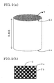
- a section means a section vertical to a longitudinal direction (X-axis direction in FIG. 2(a)) of a through channel unless otherwise mentioned.
- the filter includes at least two end faces 42 and 44, porous partition walls 2 extending from one end face 42 to the other end face 44, and through channels 3a and 3b partitioned by the partition walls 2 and extending from one end face 42 through the other end face 44.
- the predetermined through channels 3a are plugged in one end face 42, and the remaining predetermined through channels 3b are plugged in the other end face 44 (not shown).
- the filter when used as a filter 1 for purifying an exhaust gas from an internal combustion engine 50 as shown in FIG. 3, and, for example, when the exhaust gas is allowed to flow into the end face 42, the exhaust gas flows into the filter from the through channels 3b opened in the end face 42, passes through the porous partition walls 2, and is exhausted from the through channels 3a opened in the end face 44.
- the partition walls 2 function as the filter, and, for example, the PM and the like exhausted from a diesel engine can be captured and removed in the filter.
- the pressure loss is decomposed into at least a pressure loss in a plugged portion (hereinafter referred to as the plugging pressure loss), a pressure loss in the through channel (hereinafter referred to as the in-channel pressure loss), and a pressure loss during passage of the gas through the partition walls (hereinafter referred to as the wall passage pressure loss), and the wall passage pressure loss is decomposed into a pressure loss in a case where any PM is not deposited in the filter (hereinafter referred to as the initial wall passage pressure loss) and a pressure loss in a case where the PM is deposited (hereinafter referred to as the PM pressure loss) to calculate the pressure loss, which is regarded as important characteristics.
- the pressure loss is decomposed into factors as described above, and constants in a pressure loss theoretical formula are experimentally obtained with respect to the respective factors, the pressure loss of the filter at the time
- Equation (1) The pressure loss by the filter in the exhaust emission control system is decomposed as described above, and can accordingly be represented by Equation (1).
- ⁇ P ⁇ Pm+ ⁇ Pc+ ⁇ Pwc+ ⁇ Pws
- ⁇ P denotes a value of the pressure loss by the filter
- ⁇ Pm denotes a value of the plugging pressure loss
- ⁇ Pc denotes a value of the in-channel pressure loss
- ⁇ Pwc denotes a value of the initial wall passage pressure loss
- ⁇ Pws denotes a value of the PM pressure loss, respectively.
- the plugging pressure loss is considered to be caused by contraction and expansion accompanying a change of a flow path sectional area of an exhaust gas in a plugged portion, and can be obtained, when the plugged portions in the filter 1 are cut from the filter 1 as shown in FIG. 4, and the pressure loss of only the plugged portion is measured.
- the pressure loss can be measured at various flow rates with respect to the filters having various partition wall thicknesses and any number of through channels per unit section area (hereinafter referred to as the cell density).
- the plugging pressure loss can be represented by Equations (2), (3) using a pressure coefficient ⁇ which can be obtained from experiments.
- Equation (2) p denotes a density of the exhaust gas, v denotes a flow rate of the exhaust gas, and ⁇ denotes an index which can be experimentally obtained.
- C 1 , D1 denote a coefficient and an index which can be experimentally obtained, and OFA denotes an opening area ratio of the through channels to a total area.
- ⁇ Pc is generally proportional to viscosity, rate, and flow length of the exhaust gas, inversely proportional to square of a hydraulic diameter, and can be represented by Equation (4).
- the in-channel pressure loss can be measured using a honeycomb structure which does not include any plugged portion.
- ⁇ Pc C 2 v m L ⁇ /(OFA)/(DH) 2
- Equation (4) C 2 and m denote a coefficient and an index which can be obtained by the experiments, respectively, v denotes the flow rate of the exhaust gas, ⁇ denotes the viscosity of the exhaust gas, L denotes a length of the through channel, OFA denotes the opening area ratio of the through channels to the total area, and DH denotes the hydraulic diameter.
- a relation between a PM deposited amount per unit filter area of the partition wall in the DPF and the pressure loss of the whole DPF is measured, and an obtained increase behavior of the pressure loss is curve-fitted as a function of a deposited ratio of the PM, a relation between the increase of the pressure loss and the deposited amount of the PM can be obtained.
- a curve-fitting method is not especially restricted, and a general method of recurrent analysis can be used.
- the pressure loss at a time when the gas passes through the partition wall and a PM deposited layer can be represented by Equation (6).
- 1/(u 0 ⁇ 0 ) 6.3 ⁇ 10 6
- k denotes an apparent degree (m 2 ) of gas transmission at the time when the gas passes through the partition wall and the PM layer
- t denotes a total thickness (m) of the partition wall and the PM layer deposited on the partition wall
- t p denotes an apparent PM layer thickness (m)
- k 0 denotes the degree (m 2 ) of gas transmission of only the partition wall
- t 0 denotes a partition wall thickness (m)
- u denotes a flow rate (m/s) of the gas which passes through the partition wall
- ⁇ denotes a viscosity (Pas) of the gas
- u 0 denotes a standard flow rate (m/s) of the gas
- ⁇ 0 denotes a viscosity (Pas) of the gas in a standard state
- f(t p ) denotes an increase of the pressure loss accompanying the
- the pressure loss is not attributed to the filter itself, but the pressure loss attributed to the exhaust pipe connected to the filter is also preferably taken into consideration.
- the pressure loss is considered to be caused by the contraction and expansion of the exhaust gas, and can be represented by Equation (7).
- ⁇ Pd 2 ⁇ v 1 2 (1-d 1 2 /D 2 ) 2
- Equation (7) ⁇ denotes the viscosity of the gas, v 1 denotes the exhaust gas flow rate (m/s) in the exhaust pipe, d 1 denotes a diameter (m) of the exhaust pipe, and D denotes a diameter (m) of the filter, respectively.
- Equation (8) the pressure loss attributed to the filter can be represented by Equation (8).
- the pressure loss by the filter When the pressure loss by the filter is decomposed into at least four factors, further the pressure loss by the exhaust pipe connected to the filter is preferably added, and the coefficients are derived from the respective experimental results, the pressure loss by the filter can be calculated with better accuracy.
- Filter A in which segments each having a basic sectional shape of a 35 mm ⁇ 35 mm square are integrated to form a cylindrical shape having a diameter of 144 mm ⁇ a length of 245 mm and which has the following filter characteristics, a relation among the pressure loss, the cell density, and the partition wall thickness is calculated on the following calculation conditions based on Equation (8) and is shown in FIG. 7.
- the pressure loss uniquely drops, when the cell density is increased in order to increase a filter area.
- a pressure loss value is minimized in the vicinity of a cell density of about 39 cells/cm 2 , and the pressure loss increases, when the cell density is not less than the value. This is considered to be attributed to the increase of the in-channel pressure loss by a decrease of the hydraulic diameter. It has also been confirmed that the smaller the partition wall thickness is, the wall passage pressure loss drops.
- the pressure loss in the case where the PM is deposited can be calculated with respect to the filter having the predetermined material and characteristics.
- the derived pressure loss indicates a minimum value with a specific cell density in a predetermined partition wall thickness as shown in FIG. 7. Therefore, during the manufacturing of the filter, the partition wall thickness and the cell density can be determined in an appropriate range in which the pressure loss drops based on the value of the pressure loss calculated with respect to the filter having the specific material and shape.
- the cell density and the partition wall thickness may be determined beforehand, and the material and the specific characteristics of the filter may also be determined based on the calculated value of the pressure loss.
- the shape of the filter is preferably determined in consideration of the reduction of the temperature gradient in the filter.
- the temperature rise and the temperature gradient in the DPF by the burning of the PM at the time of regeneration depend on a thermal capacity of the DPF. Therefore, when the partition wall thickness and the cell density are set to appropriate values, an excessive rise of temperature in the DPF can be prevented, and the temperature gradient in the DPF can be reduced.
- the relation among the partition wall thickness, the cell density, and the temperature gradient in the filter can be measured, for example, when the DPFs having various partition wall thicknesses and cell densities are prepared, and actually attached to the exhaust pipe of the diesel engine. In this case, when a predetermined amount of PM is deposited, the exhaust gas temperature is raised to burn the PM deposited in the DPF.
- the partition wall thickness and the cell density in appropriate ranges with respect to the pressure loss preferably further the partition wall thickness and the cell density in appropriate ranges with respect to the temperature gradient are derived
- the partition wall thickness and the cell density in optimum ranges with respect to both the pressure loss and the temperature gradient can be derived.
- a filter having the partition wall thickness and the cell density in the optimum ranges can be manufactured which is usable in the exhaust emission control system according to the first aspect of the present invention.
- the exhaust emission control system of the first aspect is a system including: an internal combustion engine 50; a filter 1 which captures PM in an exhaust gas exhausted from the internal combustion engine 50; and an exhaust pipe 52 which introduces the exhaust gas exhausted from the internal combustion engine 50 into the filter 1 as shown in FIG. 3.
- the system further includes a combustion means or device which intermittently burns the PM captured by the filter. Moreover, as shown in FIGS.
- the filter 1 includes at least two end faces 42 and 44, porous partition walls 2 extending from one end face 42 to the other end face 44, and through channels 3a and 3b partitioned by the partition walls 2 and extending from one end face 42 through the other end face 44, the predetermined through channels 3a are plugged in one end face 42, and the remaining predetermined through channels 3b are plugged in the other end face 44 (not shown).
- An oxidation catalyst 54 is preferably disposed in a stage before the filter for a purpose of burning unburned carbohydrate and carbon monoxide exhausted in a diesel exhaust gas in the stage before the filter.
- the oxidation catalyst is disposed, and when, for example, a fuel injection time is adjusted to raise the exhaust gas temperature, unburned contents (carbohydrate, carbon monoxide, etc.) in the exhaust gas burn by this oxidation catalyst, and a reaction heat is produced. Therefore, the catalyst is advantageously disposed, but this is not an essential requirement for the first aspect of the present invention, and the catalyst does not have to be especially disposed.
- the exhaust gas flowing into the filter from the internal combustion engine flows into the through channels 3b opened in the end face 42, passes through the porous partition walls 2, and is exhausted from the through channels 3a opened in the end face 44.
- the partition walls 2 constitute the filter, the PM and the like exhausted, for example, from the diesel engine can be captured and removed in the filter, the captured PM is intermittently burned by the combustion means or device, and the filter can be periodically regenerated.
- a partition wall thickness is (X) ⁇ m
- the cell density is (Y) cells/cm 2
- X and Y fall: within a range of straight lines connecting points A1 (X is 267, Y is 50.4), B1 (X is 343, Y is 27.1), C1 (X is 470, Y is 27.1), and D1 (X is 394, Y is 50.4) in this order in FIG.
- This range is a range obtained by calculating the pressure loss according to the second aspect of the present invention, determining the cell density and the partition wall thickness in the appropriate ranges in which the pressure loss is reduced according to the third aspect, and further considering that a maximum temperature gradient in the filter be reduced. With the partition wall thickness and the cell density falling in this range, an exhaust emission control system can be achieved in which the pressure loss is small and the temperature gradient in the filter generated at the time of the burning of the PM captured by the filter is small.
- the partition wall thickness and the cell density optimum for the pressure loss and the temperature gradient can be derived.
- the internal combustion engine in the first aspect of the present invention is not especially restricted as long as the internal combustion engine contains the PM to be purified in the exhaust gas, but is preferably a diesel engine which contains a large amount of particulate matters.
- a means or device for intermittently burning the PM captured by the filter include a means or device for raising the temperature of the filter by a heater, a means or device using a burner, and an exhaust gas temperature raising means or device for raising the exhaust gas temperature, and the means or device is not especially restricted.
- the exhaust gas temperature raising means or device is especially preferable. In this method, there is a tendency that the temperature gradient generated in the filter increases, and the method can be effectively applied to the first aspect of the present invention.
- the exhaust gas temperature raising means or device the exhaust gas temperature is preferably raised, for example, by an adjustment device which adjusts the supply time of the fuel to the internal combustion engine.
- the fuel injection time can be comparatively easily changed.
- the injection time of the fuel can be changed to raise the exhaust gas temperature.
- An injection device which injects a part of the fuel is also preferably disposed in the exhaust pipe, accordingly the burning occurs in the exhaust pipe, and the exhaust gas temperature can be raised.
- the exhaust emission control system of the first aspect of the present invention preferably includes a means or device which lowers the burning temperature of the PM deposited on the filter in that the burning can be easily performed, and the exhaust gas temperature raising means or device is especially preferably combined and used.
- the exhaust gas temperature raising means or device does not easily raise the temperature at a high temperature as compared with the combustion means or device of the PM by the heater or the like, and it is therefore effective to lower the burning temperature.
- the means or device which lowers the burning temperature for example, an auxiliary agent adding device or the like is preferable, accordingly an auxiliary agent can be added into the fuel quantitatively.
- the added auxiliary agent is taken into the PM, and captured in the DPF, and the burning temperature of the PM can be lowered by a catalytic function of the auxiliary agent.
- the means or device which lowers the burning temperature of the PM is not restricted to only the auxiliary agent adding device, and may include any means or device that lowers the burning temperature.
- the exhaust emission control system of the first aspect of the present invention preferably includes a means, matter, or device which promotes the burning of the PM in that the burning can be easily performed.
- the means, matter, or device which promotes the burning of the PM is not especially restricted, and may include any promoting means, matter, or device.
- materials constituting the filter are not especially restricted, but various ceramic materials containing oxide or non-oxide as a main component are preferable from viewpoints of strength, heat resistance, and durability.
- Ceramic materials containing oxide or non-oxide as a main component are preferable from viewpoints of strength, heat resistance, and durability.
- Concrete examples are considered to include cordierite, mullite; alumina, spinel, silicon carbide, silicon nitride, lithium aluminum silicate, aluminum titanate, and the like.
- One or two or more selected from them are preferably used as the main components, and especially cordierite, silicon carbide, or a silicon-silicon carbide based material is preferable.
- the "main component” means that the component constitutes 50% by mass or more, preferably 70% by mass or more, further preferably 80% by mass or more of the filter.
- the filter is preferably a filter in which a plurality of segments are integrated, or a filter including slits.
- the filter is divided into a plurality of segments, and the segments are integrated, or the slits are formed in the filter, a thermal stress is scattered, and cracks by the thermal stress can be prevented.
- the filter is segmented and integrated, a size or shape of each segment is not restricted. However, when each segment is excessively large, an effect of preventing the cracks by segmentation is not sufficiently fulfilled. When the segment is excessively small, the manufacturing of the respective segments or the integrating thereof by bonding unfavorably becomes complicated.
- a sectional area is 900 to 10000 mm 2 , further preferably 900 to 5000 mm 2 , and most preferably 900 to 3600 mm 2 , and 70% by volume or more of the filter is preferably constituted of the honeycomb segment having this size.
- a preferable shape of the segment for example, a quadrangular sectional shape, that is, the segment having a square pole shape is regarded as a basic shape, and the shape of the segment on an outer peripheral side can be appropriately selected in accordance with the shape of the integrated filter.
- the whole sectional shape of the filter is not especially restricted, and is not limited to a circular shape shown in FIG.
- a race track shape a substantially circular shape such as an oblong shape, a quadrangular shape, and a polygonal shape such as a hexagonal shape may also be used.
- the partition walls of the filter in the first aspect of the present invention are porous, but a pore diameter and a porosity of the partition wall are not especially restricted, and can be appropriately selected in accordance with the application by any person skilled in the art.
- the pore diameter can be selected in accordance with a particle diameter of the PM or the like.
- the average pore diameter is preferably set to about 5 to 70 ⁇ m, further preferably about 10 to 50 ⁇ m, especially preferably about 15 to 30 ⁇ m.
- the porosity can be similarly appropriately selected in accordance with the application. When the porosity is excessively small, an initial pressure loss is excessively large. When the porosity is excessively large, strength unfavorably becomes insufficient.
- the preferable porosity for use in the DPF is in a range of 30 to 90%.
- the porosity is less than 30%, the pressure loss becomes excessively large.
- the porosity exceeds 90%, the strength of the ceramic material runs short.
- the thermal conductivity of the filter is not especially restricted, but is preferably 8 to 70 W/mK, further preferably 10 to 55 W/mK.
- the method of manufacturing the filter is not especially restricted, but the filter can be manufactured, for example, by the following method.
- a material selected from the above-described preferable materials for example, a silicon carbide powder is used as a raw material powder of the filter, binders such as methyl cellulose and hydroxypropoxyl methyl cellulose are added to the powder, and further surfactant and water are added to obtain plastic clay.
- the partition wall thickness and the cell density in the appropriate ranges are determined according to the third aspect of the present invention, an extruder including a ferrule which forms the shape is used, the obtained clay is extrusion-molded, and accordingly a molded article having a honeycomb structure is obtained. This article is dried, for example, by microwaves and hot air, and thereafter one-end portions of adjacent through channels on opposite sides are plugged with a material similar to that used in manufacturing the filter.
- the article is further dried, heated/degreased, for example, in a nitrogen atmosphere, and thereafter calcined in an inactive atmosphere such as argon so that the filter can be obtained.
- a calcining temperature and a calcining atmosphere differ with the raw material, and any person skilled in the art can select the calcining temperature and calcining atmosphere which are appropriate for the selected ceramic raw material.
- the obtained segments are bonded, for example, using ceramic cement, and dried/hardened so that the filter can be obtained.
- a method of imparting the catalyst to the filter manufactured in this manner may be a method usually performed by the person skilled in the art. For example, when a catalyst slurry is wash-coated, dried, and calcined, the catalyst can be supported.
- a filter having the same characteristics as those of Filter A used in the description of the second aspect of the present invention and having a cell density of 46.5 cells/cm 2 , and a partition wall thickness of 305 ⁇ m was prepared.
- the filter was attached to a diesel engine in a constitution shown in FIG. 3, a relation between a deposited amount of PM and a pressure loss was actually measured on conditions of a gas amount of 2.27 Nm 3 /min. and an inflow gas temperature at 200°C, and actual measurement was compared with a calculated value calculated using Equation (8). Results are shown in FIG. 8, and the actual measurement matched the calculated value very well.
- Filters having the same filter characteristics as those of Filter A and having cell densities and partition wall thicknesses shown in Table 1 were prepared.
- the filter was attached to a system including a 2.0 liter diesel engine and an auxiliary agent adding device in a basic constitution shown in FIG. 3 to constitute an exhaust emission control system.
- the auxiliary agent adding device was used, 25 ppm of a Ce fuel auxiliary agent was added to fuel, and the system was operated.
- a PM deposited amount per unit filter volume reached 6 kg/m 3
- the exhaust gas temperature was raised at 600°C to burn the PM, regeneration of the filter was evaluated, and a maximum temperature gradient in each segment was measured. Results are shown in Table 1 and FIG. 9.
- an exhaust emission control system is a satisfactory system in which a pressure loss at the time of PM deposition is small, a maximum temperature gradient in a filter at the time of filter regeneration by PM burning is small, and the filter is not easily cracked.
- a value obtained by a method of calculating a pressure loss according to a second aspect of the present invention satisfactory agreement with actual measurement is seen, and the pressure loss can be measured with good accuracy.
- a filter which falls in the scope of the first aspect of the present invention can be easily prepared according to a third aspect of the present invention.
Landscapes
- Engineering & Computer Science (AREA)
- Chemical & Material Sciences (AREA)
- Physics & Mathematics (AREA)
- Geometry (AREA)
- Combustion & Propulsion (AREA)
- Mechanical Engineering (AREA)
- General Engineering & Computer Science (AREA)
- Chemical Kinetics & Catalysis (AREA)
- Processes For Solid Components From Exhaust (AREA)
- Filtering Of Dispersed Particles In Gases (AREA)
Abstract
There are disclosed an exhaust emission control
system including an internal combustion engine, a filter,
and an exhaust pipe, a method of manufacturing a filter
suitable for the system, and a method of calculating a
pressure loss. The system comprises combustion means for
intermittently burning particulate matters arrested by the
filter, the filter includes porous partition walls
extending from one end face to the other end face thereof,
and a large number of through channels partitioned by the
partition walls, predetermined through channels are sealed
at either of the end faces, and assuming that a partition
wall thickness is (X) µm, and the number of through
channels per unit area in a cross section vertical to a
longitudinal direction of the through channels is (Y)
cells/cm2, X and Y come within a range surrounded by
straight lines connecting points A1, B1, C1, and D1 in this
order in FIG. 1 in the exhaust emission control system.
There are provided the exhaust emission control system, the
method of manufacturing the filter, and the method of
calculating the pressure loss by the filter with good
accuracy in which a temperature gradient produced in the
filter at the time of regeneration is suppressed while
suppressing a rise of the pressure loss by the filter and
which are accordingly superior in reliability.
Description
The present invention relates to an exhaust
emission control system, a method of calculating a pressure
loss by a filter, and a method of manufacturing a filter,
particularly to an exhaust emission control system in which
a pressure loss is small and a temperature gradient
generated in a filter at the time of combustion is small, a
calculation method capable of calculating a pressure loss
by a filter in an exhaust emission control system with good
accuracy, and a method of manufacturing a filter, in which
an appropriate filter shape can be easily determined.
As a conventional exhaust emission control system
for efficiently removing particulate matters (hereinafter
referred to as PM) exhausted from an internal combustion
engine, a system using a diesel particulate filter
(hereinafter referred to as DPF) has heretofore been
proposed. Unless the captured PM is removed in the system
using the DPF, the filter is finally clogged, and therefore
the filter needs to be periodically regenerated.
In general, the regeneration of the filter is
possible, when the DPF is heated and burnt. However, for
example, an exhaust gas temperature of a diesel engine does
not easily reach to a burning temperature of the PM.
Therefore, there has been considered a method in which the
temperature of the DPF is raised by external heat sources
such as an electric heater and a burner to burn soot that
is a main component of the PM, or a method in which the DPF
is periodically replaced, and the removed DPF is heated by
an electric furnace.
However, in the method in which the filter is
heated by the external heat sources such as the electric
heater and the burner, the PM deposited on the filter can
be comparatively stably burnt, but the electric heater or
the combustion burner is a complicated/expensive device,
and therefore this method has been restricted to some
special applications. In the method in which the DPF is
periodically replaced, handling of the filter has been
troublesome.
To solve the problem, there has been proposed a
system in which a time to supply fuel to an internal
combustion engine, for example, a fuel injection time in a
diesel engine or the like is adjusted to raise an exhaust
gas temperature, and the PM deposited on the filter is
periodically burnt. This system is sometimes combined with
a method for lowering the burning temperature of the PM in
order to more sufficiently burn the PM. Since the method
is a comparatively simple method, it has also been possible
to mount an exhaust emission control system in which the
DPF is used in removing the PM exhausted from the diesel
engine mounted on the automobile.
However, in the method in which the PM is
deposited on the filter, and the injection time of the
diesel engine is adjusted at a certain time interval to
raise the exhaust gas temperature, the exhaust gas
temperature rises in a remarkably short time. Therefore,
as compared with the case where the PM is burnt by the
electric furnace or the like, a rapid temperature rise in
the filter at the time of regeneration easily occurs,
additionally a temperature gradient in the filter increases,
and there has been a possibility that the filter is
disadvantageously cracked. Especially in the method for
lowering the burning temperature of the PM, activation
energy of the PM is lowered. Therefore, as compared with a
case where the PM is simply burnt by the exhaust gas
temperature rise from the engine, the PM is burnt in a
comparatively short time, thermal energy received by the
DPF per unit time increases, an excessive temperature
distribution is made in the DPF, and there has been a
possibility that the DPF is more easily cracked or that
materials are molten.
On the other hand, the filter has a mechanism in
which openings of cells of a honeycomb structure
constituted of a porous ceramic are alternately sealed, and
the PM is captured during passing of the exhaust gas
through porous honeycomb walls. During the passing of the
exhaust gas through the walls, emission resistance is
generated, and there is a problem that a difference in
pressure loss before/after the filter increases. When the
pressure difference increases, an output from the engine
drops. Therefore, to obtain the same performance, as
compared with a case where the filter is not mounted, much
more fuel is required. When the pressure difference
excessively increases, there is a possibility that the fuel
does not burn well in the engine and the engine does not
operate disadvantageously. Therefore, it is an important
function of the filter to reduce the pressure loss
difference before/after the filter.
Moreover, when a fuel auxiliary agent is used for
lowering the burning temperature of the PM, and when the
fuel auxiliary agent burns together with the PM, a large
amount of ashes are generated, and there is a problem that
a back pressure before/after the filter increases. Even in
a method in which a catalyst is imparted to the filter, the
catalyst itself or a washed coating of the catalyst closes
pores in the filter, and therefore there is a problem that
the pressure loss in the filter increases. Therefore, in
the exhaust emission control system, it has been necessary
to suppress the increase of the pressure loss to the utmost
while well suppressing a filter temperature at the time of
regeneration.
On the other hand, various methods of calculation
of the pressure loss of the filter have heretofore been
proposed, but the pressure loss can be calculated well on
conditions that any PM is not deposited on the filter, but
it has not been possible to calculate the pressure loss in
a case where the PM is deposited. Therefore, since it is
difficult to calculate the pressure loss of the filter at
the time of actual use in the exhaust emission control
system with good accuracy, it is difficult to predict an
optimum filter structure in which the pressure loss is well
balanced with the filter temperature at the time of
regeneration. There has been a demand for a method of
calculating the pressure loss with good accuracy in order
to obtain the exhaust emission control system provided with
the above-described optimum filter.
The present invention has been developed in
consideration of circumstances, and an object is to provide
an exhaust emission control system in which a rise of a
pressure loss by a filter is suppressed while suppressing a
temperature gradient generated in the filter at the time of
regeneration and which is accordingly superior in
reliability. Another object of the present invention is to
provide a method of measuring a pressure loss by a filter
with good accuracy. Still another object of the present
invention is to provide a method of manufacturing a filter,
capable of easily determining an appropriate shape of the
filter preferably usable in the above-described exhaust
emission control system.
According to the present invention, there is first
provided an exhaust emission control system including: an
internal combustion engine; a filter for capturing
particulate matters in an exhaust gas exhausted from the
internal combustion engine; and an exhaust pipe for
introducing the exhaust gas into the filter, the system
comprising a combustion means or device for intermittently
burning the particulate matters captured by the filter, the
filter being a honeycomb filter including: at least two end
faces; porous partition walls extending from one end face
to the other end face; and a large number of through
channels partitioned by the partition walls and extending
from one end face through the other end face, predetermined
through channels being sealed in one end face, remaining
predetermined through channels being sealed in the other
end face, wherein assuming that a partition wall thickness
is (X) µm, and the number of through channels per unit area
in a section vertical to a longitudinal direction of the
through channels is (Y) cells/cm2, X and Y fall within a
range surrounded by straight lines connecting points A1 (X
is 267, Y is 50.4), B1 (X is 343, Y is 27.1), C1 (X is 470,
Y is 27.1), and D1 (X is 394, Y is 50.4) in this order in
FIG. 1.
In the first aspect of the present invention, the
X and Y preferably fall within a range surrounded by
straight lines connecting points A2 (X is 305, Y is 46.5),
B2 (X is 356, Y is 31.0), C2 (X is 432, Y is 31.0), and D2
(X is 381, Y is 46.5) in this order in FIG. 1, and the X
and Y further preferably fall within a range surrounded by
straight lines connecting points A3 (X is 330, Y is 42.7),
B3 (X is 356, Y is 34.9), C3 (X is 406, Y is 34.9), and D3
(X is 381, Y is 42.7) in this order in FIG. 1. The
internal combustion engine is preferably a diesel engine.
The combustion means or device preferably includes an
exhaust gas temperature raising means or device for raising
a temperature of the exhaust gas in such a manner as to
start the burning of the particulate matters captured by
the filter, and the exhaust gas temperature raising means
or device further preferably includes an adjustment device
for adjusting a time to supply fuel to the internal
combustion engine. The exhaust gas temperature raising
means or device also preferably includes a supply device
for supplying the fuel into the exhaust pipe. The exhaust
emission control system preferably further includes a means
or device for lowering the burning temperature of the
particulate matters captured by the filter, and the exhaust
emission control system also preferably includes a means,
matter, or device for promoting the burning of the
particulate matters captured by the filter. The filter
preferably contains a ceramic material as a main component,
and the filter is also preferably constituted of a
plurality of integrated segments of a honeycomb structure.
According to the present invention, there is
secondly provided a method of calculating a pressure loss
of a honeycomb filter including: at least two end faces;
porous partition walls extending from one end face to the
other end face; and a large number of through channels
partitioned by the partition walls and extending from one
end face through the other end face, predetermined through
channels being plugged in one end face, remaining
predetermined through channels being plugged in the other
end face, the method comprising the steps of: decomposing
the pressure loss into at least a pressure loss in a
plugged portion, a pressure loss in the through channel,
and a pressure loss in the partition wall; and decomposing
the pressure loss in the partition wall into pressure
losses in cases where any particulate matter is not
deposited in the filter and where the particulate matters
are deposited to calculate the pressure loss. In the
second aspect of the present invention, the method
preferably comprises the steps of: measuring the pressure
loss in the case where the particulate matters are
deposited in the predetermined filter; and calculating the
pressure loss in the partition wall in the case where the
particulate matters are deposited in the filter based on an
equation obtained by curve fitting of an increase behavior
of the obtained pressure loss.
According to the present invention, there is
thirdly provided a method of manufacturing a filter,
wherein a shape of the filter is determined by use of a
pressure loss value obtained by the calculation method
according to the second aspect of the present invention.
An exhaust emission control system according to a
first aspect of the present invention, a method of
calculating a pressure loss by a filter in the exhaust
emission control system according to a second aspect, and a
method of manufacturing a filter according to a third
aspect will be described hereinafter with reference to the
drawings, but the present invention is not limited to the
following embodiment. It is to be noted that in the
following, a section means a section vertical to a
longitudinal direction (X-axis direction in FIG. 2(a)) of a
through channel unless otherwise mentioned.
First, a method of calculating a pressure loss of
a filter according to the second aspect of the present
invention will be described.
In an example of the filter according to the
second aspect of the present invention, as shown in FIGS.
2(a), (b), the filter includes at least two end faces 42
and 44, porous partition walls 2 extending from one end
face 42 to the other end face 44, and through channels 3a
and 3b partitioned by the partition walls 2 and extending
from one end face 42 through the other end face 44. The
predetermined through channels 3a are plugged in one end
face 42, and the remaining predetermined through channels
3b are plugged in the other end face 44 (not shown).
In this constitution, when the filter is used as a
filter 1 for purifying an exhaust gas from an internal
combustion engine 50 as shown in FIG. 3, and, for example,
when the exhaust gas is allowed to flow into the end face
42, the exhaust gas flows into the filter from the through
channels 3b opened in the end face 42, passes through the
porous partition walls 2, and is exhausted from the through
channels 3a opened in the end face 44. In this case, the
partition walls 2 function as the filter, and, for example,
the PM and the like exhausted from a diesel engine can be
captured and removed in the filter.
According to the second aspect of the present
invention, there is provided a method of calculating a
pressure loss at a time when the exhaust gas passes through
the above-described filter. The pressure loss is
decomposed into at least a pressure loss in a plugged
portion (hereinafter referred to as the plugging pressure
loss), a pressure loss in the through channel (hereinafter
referred to as the in-channel pressure loss), and a
pressure loss during passage of the gas through the
partition walls (hereinafter referred to as the wall
passage pressure loss), and the wall passage pressure loss
is decomposed into a pressure loss in a case where any PM
is not deposited in the filter (hereinafter referred to as
the initial wall passage pressure loss) and a pressure loss
in a case where the PM is deposited (hereinafter referred
to as the PM pressure loss) to calculate the pressure loss,
which is regarded as important characteristics. When the
pressure loss is decomposed into factors as described above,
and constants in a pressure loss theoretical formula are
experimentally obtained with respect to the respective
factors, the pressure loss of the filter at the time of
actual use can be calculated with good accuracy.
The pressure loss by the filter in the exhaust
emission control system is decomposed as described above,
and can accordingly be represented by Equation (1).
ΔP = ΔPm+ΔPc+ΔPwc+ΔPws
In the Equation (1), ΔP denotes a value of the
pressure loss by the filter, ΔPm denotes a value of the
plugging pressure loss, ΔPc denotes a value of the in-channel
pressure loss, ΔPwc denotes a value of the initial
wall passage pressure loss, and ΔPws denotes a value of the
PM pressure loss, respectively.
The plugging pressure loss is considered to be
caused by contraction and expansion accompanying a change
of a flow path sectional area of an exhaust gas in a
plugged portion, and can be obtained, when the plugged
portions in the filter 1 are cut from the filter 1 as shown
in FIG. 4, and the pressure loss of only the plugged
portion is measured. The pressure loss can be measured at
various flow rates with respect to the filters having
various partition wall thicknesses and any number of
through channels per unit section area (hereinafter
referred to as the cell density). The plugging pressure
loss can be represented by Equations (2), (3) using a
pressure coefficient ξ which can be obtained from
experiments.
ΔPm = ξρvα
ξ = C1 (1-OFA)D1
In the Equation (2), p denotes a density of the
exhaust gas, v denotes a flow rate of the exhaust gas, and
α denotes an index which can be experimentally obtained.
In the Equation (3), C1, D1 denote a coefficient and an
index which can be experimentally obtained, and OFA denotes
an opening area ratio of the through channels to a total
area.
Since the exhaust gas is considered to constitute
a laminar flow when passing through the through channels,
ΔPc is generally proportional to viscosity, rate, and flow
length of the exhaust gas, inversely proportional to square
of a hydraulic diameter, and can be represented by Equation
(4). The in-channel pressure loss can be measured using a
honeycomb structure which does not include any plugged
portion.
ΔPc = C2 vm Lµ/(OFA)/(DH)2
In Equation (4), C2 and m denote a coefficient and
an index which can be obtained by the experiments,
respectively, v denotes the flow rate of the exhaust gas, µ
denotes the viscosity of the exhaust gas, L denotes a
length of the through channel, OFA denotes the opening area
ratio of the through channels to the total area, and DH
denotes the hydraulic diameter.
It is considered that Darcy's law can be applied
to the wall passage pressure loss. A degree of gas
transmission of only the partition wall in a state in which
any PM is not deposited can be measured, when the partition
wall 2 is set onto a device shown in FIG. 5, and the degree
can be represented by Equation (5).
(Degree of gas transmission) = {(flow rate of
gas)×(partition wall thickness)×(viscosity of
gas)}/(pressure loss) (5)
Here, for example, when a relation between a PM
deposited amount per unit filter area of the partition wall
in the DPF and the pressure loss of the whole DPF is
measured, and an obtained increase behavior of the pressure
loss is curve-fitted as a function of a deposited ratio of
the PM, a relation between the increase of the pressure
loss and the deposited amount of the PM can be obtained.
Here, a curve-fitting method is not especially restricted,
and a general method of recurrent analysis can be used.
Moreover, the pressure loss at a time when the gas passes
through the partition wall and a PM deposited layer can be
represented by Equation (6).

In the Equation (6),
1/(u0 µ0 ) = 6.3×10⁶ ,
k denotes an apparent degree (m2) of gas
transmission at the time when the gas passes through the
partition wall and the PM layer,
t denotes a total thickness (m) of the partition wall and the PM layer deposited on the partition wall,
tp denotes an apparent PM layer thickness (m),
k0 denotes the degree (m2) of gas transmission of only the partition wall;
t0 denotes a partition wall thickness (m),
u denotes a flow rate (m/s) of the gas which passes through the partition wall,
µ denotes a viscosity (Pas) of the gas
u0 denotes a standard flow rate (m/s) of the gas,
µ0 denotes a viscosity (Pas) of the gas in a standard state; and
f(tp) denotes an increase of the pressure loss accompanying the increase of the deposited amount of the PM under conditions of u0 and µ0, respectively.
t denotes a total thickness (m) of the partition wall and the PM layer deposited on the partition wall,
tp denotes an apparent PM layer thickness (m),
k0 denotes the degree (m2) of gas transmission of only the partition wall;
t0 denotes a partition wall thickness (m),
u denotes a flow rate (m/s) of the gas which passes through the partition wall,
µ denotes a viscosity (Pas) of the gas
u0 denotes a standard flow rate (m/s) of the gas,
µ0 denotes a viscosity (Pas) of the gas in a standard state; and
f(tp) denotes an increase of the pressure loss accompanying the increase of the deposited amount of the PM under conditions of u0 and µ0, respectively.
In the second aspect of the present invention, the
pressure loss is not attributed to the filter itself, but
the pressure loss attributed to the exhaust pipe connected
to the filter is also preferably taken into consideration.
The pressure loss is considered to be caused by the
contraction and expansion of the exhaust gas, and can be
represented by Equation (7).
ΔPd = 2ρv1 2 (1-d1 2 /D2 )2
In Equation (7), ρ denotes the viscosity of the
gas, v1 denotes the exhaust gas flow rate (m/s) in the
exhaust pipe, d1 denotes a diameter (m) of the exhaust pipe,
and D denotes a diameter (m) of the filter, respectively.
When the pressure loss is taken into consideration,
the pressure loss attributed to the filter can be
represented by Equation (8).
ΔP (including the exhaust pipe) = ΔP
= ΔPm+ΔPc+ΔPwc+ΔPws+ΔPd (8)
When the pressure loss by the filter is decomposed
into at least four factors, further the pressure loss by
the exhaust pipe connected to the filter is preferably
added, and the coefficients are derived from the respective
experimental results, the pressure loss by the filter can
be calculated with better accuracy. In accordance with an
example of Filter A in which segments each having a basic
sectional shape of a 35 mm × 35 mm square are integrated to
form a cylindrical shape having a diameter of 144 mm × a
length of 245 mm and which has the following filter
characteristics, a relation among the pressure loss, the
cell density, and the partition wall thickness is
calculated on the following calculation conditions based on
Equation (8) and is shown in FIG. 7.
It has heretofore been considered that the
pressure loss uniquely drops, when the cell density is
increased in order to increase a filter area. However, by
this analysis, it has been found that with the equal
partition wall thickness, a pressure loss value is
minimized in the vicinity of a cell density of about 39
cells/cm2, and the pressure loss increases, when the cell
density is not less than the value. This is considered to
be attributed to the increase of the in-channel pressure
loss by a decrease of the hydraulic diameter. It has also
been confirmed that the smaller the partition wall
thickness is, the wall passage pressure loss drops.
Next, a method of manufacturing a filter according
to a third aspect of the present invention will be
described. According to the second aspect of the present
invention, the pressure loss in the case where the PM is
deposited can be calculated with respect to the filter
having the predetermined material and characteristics.
Moreover, the derived pressure loss indicates a minimum
value with a specific cell density in a predetermined
partition wall thickness as shown in FIG. 7. Therefore,
during the manufacturing of the filter, the partition wall
thickness and the cell density can be determined in an
appropriate range in which the pressure loss drops based on
the value of the pressure loss calculated with respect to
the filter having the specific material and shape. The
cell density and the partition wall thickness may be
determined beforehand, and the material and the specific
characteristics of the filter may also be determined based
on the calculated value of the pressure loss.
In the third aspect of the present invention, the
shape of the filter is preferably determined in
consideration of the reduction of the temperature gradient
in the filter. For example, in an example of DPF, the
temperature rise and the temperature gradient in the DPF by
the burning of the PM at the time of regeneration depend on
a thermal capacity of the DPF. Therefore, when the
partition wall thickness and the cell density are set to
appropriate values, an excessive rise of temperature in the
DPF can be prevented, and the temperature gradient in the
DPF can be reduced. The relation among the partition wall
thickness, the cell density, and the temperature gradient
in the filter can be measured, for example, when the DPFs
having various partition wall thicknesses and cell
densities are prepared, and actually attached to the
exhaust pipe of the diesel engine. In this case, when a
predetermined amount of PM is deposited, the exhaust gas
temperature is raised to burn the PM deposited in the DPF.
When the partition wall thickness and the cell
density in appropriate ranges with respect to the pressure
loss, preferably further the partition wall thickness and
the cell density in appropriate ranges with respect to the
temperature gradient are derived, the partition wall
thickness and the cell density in optimum ranges with
respect to both the pressure loss and the temperature
gradient can be derived. For example, a filter having the
partition wall thickness and the cell density in the
optimum ranges can be manufactured which is usable in the
exhaust emission control system according to the first
aspect of the present invention.
Next, the exhaust emission control system
according to the first aspect of the present invention will
be described.
The exhaust emission control system of the first
aspect is a system including: an internal combustion engine
50; a filter 1 which captures PM in an exhaust gas
exhausted from the internal combustion engine 50; and an
exhaust pipe 52 which introduces the exhaust gas exhausted
from the internal combustion engine 50 into the filter 1 as
shown in FIG. 3. The system further includes a combustion
means or device which intermittently burns the PM captured
by the filter. Moreover, as shown in FIGS. 2(a), (b), the
filter 1 includes at least two end faces 42 and 44, porous
partition walls 2 extending from one end face 42 to the
other end face 44, and through channels 3a and 3b
partitioned by the partition walls 2 and extending from one
end face 42 through the other end face 44, the
predetermined through channels 3a are plugged in one end
face 42, and the remaining predetermined through channels
3b are plugged in the other end face 44 (not shown).
An oxidation catalyst 54 is preferably disposed in
a stage before the filter for a purpose of burning unburned
carbohydrate and carbon monoxide exhausted in a diesel
exhaust gas in the stage before the filter. When the
oxidation catalyst is disposed, and when, for example, a
fuel injection time is adjusted to raise the exhaust gas
temperature, unburned contents (carbohydrate, carbon
monoxide, etc.) in the exhaust gas burn by this oxidation
catalyst, and a reaction heat is produced. Therefore, the
catalyst is advantageously disposed, but this is not an
essential requirement for the first aspect of the present
invention, and the catalyst does not have to be especially
disposed.
By this constitution, the exhaust gas flowing into
the filter from the internal combustion engine flows into
the through channels 3b opened in the end face 42, passes
through the porous partition walls 2, and is exhausted from
the through channels 3a opened in the end face 44. In this
case, the partition walls 2 constitute the filter, the PM
and the like exhausted, for example, from the diesel engine
can be captured and removed in the filter, the captured PM
is intermittently burned by the combustion means or device,
and the filter can be periodically regenerated.
In important characteristics of the first aspect
of the present invention, assuming that a partition wall
thickness is (X) µm, and the cell density is (Y) cells/cm2,
X and Y fall: within a range of straight lines connecting
points A1 (X is 267, Y is 50.4), B1 (X is 343, Y is 27.1),
C1 (X is 470, Y is 27.1), and D1 (X is 394, Y is 50.4) in
this order in FIG. 1; preferably within a range surrounded
by straight lines connecting points A2 (X is 305, Y is
46.5), B2 (X is 356, Y is 31.0), C2 (X is 432, Y is 31.0),
and D2 (X is 381, Y is 46.5) in this order in FIG. 1; and
further preferably within a range surrounded by straight
lines connecting points A3 (X is 330, Y is 42.7), B3 (X is
356, Y is 34.9), C3 (X is 406, Y is 34.9), and D3 (X is 381,
Y is 42.7) in this order in FIG. 1.
This range is a range obtained by calculating the
pressure loss according to the second aspect of the present
invention, determining the cell density and the partition
wall thickness in the appropriate ranges in which the
pressure loss is reduced according to the third aspect, and
further considering that a maximum temperature gradient in
the filter be reduced. With the partition wall thickness
and the cell density falling in this range, an exhaust
emission control system can be achieved in which the
pressure loss is small and the temperature gradient in the
filter generated at the time of the burning of the PM
captured by the filter is small.
As described above, the larger the partition wall
thickness is and the larger the cell density is, the
temperature gradient is reduced. With respect to the
pressure loss, the cell density has a relation with a
filter area. The larger the cell density is, the filter
area increases, and the pressure loss can be reduced. The
partition wall thickness also influences the pressure loss
at a time when the gas passes through the partition walls.
The smaller the partition wall thickness is, the pressure
loss is reduced. In this manner, the partition wall
thickness and the cell density have complicated influences
on the pressure loss and the temperature behavior at the
time of the filter regeneration, and it has been difficult
to establish both the characteristics. However, by the
present invention, the partition wall thickness and the
cell density optimum for the pressure loss and the
temperature gradient can be derived.
The internal combustion engine in the first aspect
of the present invention is not especially restricted as
long as the internal combustion engine contains the PM to
be purified in the exhaust gas, but is preferably a diesel
engine which contains a large amount of particulate matters.
Examples of a means or device for intermittently burning
the PM captured by the filter include a means or device for
raising the temperature of the filter by a heater, a means
or device using a burner, and an exhaust gas temperature
raising means or device for raising the exhaust gas
temperature, and the means or device is not especially
restricted. However, the exhaust gas temperature raising
means or device is especially preferable. In this method,
there is a tendency that the temperature gradient generated
in the filter increases, and the method can be effectively
applied to the first aspect of the present invention.
As the exhaust gas temperature raising means or
device, the exhaust gas temperature is preferably raised,
for example, by an adjustment device which adjusts the
supply time of the fuel to the internal combustion engine.
For example, in the internal combustion engine including a
fuel injection device, the fuel injection time can be
comparatively easily changed. When the PM in the filter
reaches a predetermined amount, the injection time of the
fuel can be changed to raise the exhaust gas temperature.
An injection device which injects a part of the fuel is
also preferably disposed in the exhaust pipe, accordingly
the burning occurs in the exhaust pipe, and the exhaust gas
temperature can be raised.
The exhaust emission control system of the first
aspect of the present invention preferably includes a means
or device which lowers the burning temperature of the PM
deposited on the filter in that the burning can be easily
performed, and the exhaust gas temperature raising means or
device is especially preferably combined and used. This is
because the exhaust gas temperature raising means or device
does not easily raise the temperature at a high temperature
as compared with the combustion means or device of the PM
by the heater or the like, and it is therefore effective to
lower the burning temperature. As the means or device
which lowers the burning temperature, for example, an
auxiliary agent adding device or the like is preferable,
accordingly an auxiliary agent can be added into the fuel
quantitatively. When the fuel is burnt in a cylinder, the
added auxiliary agent is taken into the PM, and captured in
the DPF, and the burning temperature of the PM can be
lowered by a catalytic function of the auxiliary agent. In
the first aspect of the present invention, the means or
device which lowers the burning temperature of the PM is
not restricted to only the auxiliary agent adding device,
and may include any means or device that lowers the burning
temperature.
Moreover, the exhaust emission control system of
the first aspect of the present invention preferably
includes a means, matter, or device which promotes the
burning of the PM in that the burning can be easily
performed. The means, matter, or device which promotes the
burning of the PM is not especially restricted, and may
include any promoting means, matter, or device. However,
for example, it is preferable to apply the catalysts which
promote the burning of the PM, such as Pt, Pd, and Rh, to
the filter.
In the first aspect of the present invention,
materials constituting the filter are not especially
restricted, but various ceramic materials containing oxide
or non-oxide as a main component are preferable from
viewpoints of strength, heat resistance, and durability.
Concrete examples are considered to include cordierite,
mullite; alumina, spinel, silicon carbide, silicon nitride,
lithium aluminum silicate, aluminum titanate, and the like.
One or two or more selected from them are preferably used
as the main components, and especially cordierite, silicon
carbide, or a silicon-silicon carbide based material is
preferable. Here, the "main component" means that the
component constitutes 50% by mass or more, preferably 70%
by mass or more, further preferably 80% by mass or more of
the filter.
In the first aspect of the present invention, the
filter is preferably a filter in which a plurality of
segments are integrated, or a filter including slits. When
the filter is divided into a plurality of segments, and the
segments are integrated, or the slits are formed in the
filter, a thermal stress is scattered, and cracks by the
thermal stress can be prevented. When the filter is
segmented and integrated, a size or shape of each segment
is not restricted. However, when each segment is
excessively large, an effect of preventing the cracks by
segmentation is not sufficiently fulfilled. When the
segment is excessively small, the manufacturing of the
respective segments or the integrating thereof by bonding
unfavorably becomes complicated. In a preferable size of
the segment, a sectional area is 900 to 10000 mm2, further
preferably 900 to 5000 mm2, and most preferably 900 to 3600
mm2, and 70% by volume or more of the filter is preferably
constituted of the honeycomb segment having this size. In
a preferable shape of the segment, for example, a
quadrangular sectional shape, that is, the segment having a
square pole shape is regarded as a basic shape, and the
shape of the segment on an outer peripheral side can be
appropriately selected in accordance with the shape of the
integrated filter. The whole sectional shape of the filter
is not especially restricted, and is not limited to a
circular shape shown in FIG. 2(a), and, for example, in
addition to an elliptic shape, a race track shape, a
substantially circular shape such as an oblong shape, a
quadrangular shape, and a polygonal shape such as a
hexagonal shape may also be used.
The partition walls of the filter in the first
aspect of the present invention are porous, but a pore
diameter and a porosity of the partition wall are not
especially restricted, and can be appropriately selected in
accordance with the application by any person skilled in
the art. In general, the pore diameter can be selected in
accordance with a particle diameter of the PM or the like.
For example, when the partition walls are used in the DPF,
the average pore diameter is preferably set to about 5 to
70 µm, further preferably about 10 to 50 µm, especially
preferably about 15 to 30 µm. The porosity can be
similarly appropriately selected in accordance with the
application. When the porosity is excessively small, an
initial pressure loss is excessively large. When the
porosity is excessively large, strength unfavorably becomes
insufficient. For example, the preferable porosity for use
in the DPF is in a range of 30 to 90%. When the porosity
is less than 30%, the pressure loss becomes excessively
large. When the porosity exceeds 90%, the strength of the
ceramic material runs short. The thermal conductivity of
the filter is not especially restricted, but is preferably
8 to 70 W/mK, further preferably 10 to 55 W/mK.
The method of manufacturing the filter is not
especially restricted, but the filter can be manufactured,
for example, by the following method.
A material selected from the above-described
preferable materials, for example, a silicon carbide powder
is used as a raw material powder of the filter, binders
such as methyl cellulose and hydroxypropoxyl methyl
cellulose are added to the powder, and further surfactant
and water are added to obtain plastic clay. Moreover, for
example, the partition wall thickness and the cell density
in the appropriate ranges are determined according to the
third aspect of the present invention, an extruder
including a ferrule which forms the shape is used, the
obtained clay is extrusion-molded, and accordingly a molded
article having a honeycomb structure is obtained. This
article is dried, for example, by microwaves and hot air,
and thereafter one-end portions of adjacent through
channels on opposite sides are plugged with a material
similar to that used in manufacturing the filter. The
article is further dried, heated/degreased, for example, in
a nitrogen atmosphere, and thereafter calcined in an
inactive atmosphere such as argon so that the filter can be
obtained. A calcining temperature and a calcining
atmosphere differ with the raw material, and any person
skilled in the art can select the calcining temperature and
calcining atmosphere which are appropriate for the selected
ceramic raw material.
To form the filter into a constitution in which a
plurality of segments are integrated, after obtaining the
segments in the above-described method, the obtained
segments are bonded, for example, using ceramic cement, and
dried/hardened so that the filter can be obtained. A
method of imparting the catalyst to the filter manufactured
in this manner may be a method usually performed by the
person skilled in the art. For example, when a catalyst
slurry is wash-coated, dried, and calcined, the catalyst
can be supported.
The present invention will be described
hereinafter concretely in accordance with examples, but the
present invention is not limited to any of these examples.
Next, the present invention will be described
further concretely based on the examples.
A filter having the same characteristics as those
of Filter A used in the description of the second aspect of
the present invention and having a cell density of 46.5
cells/cm2, and a partition wall thickness of 305 µm was
prepared. The filter was attached to a diesel engine in a
constitution shown in FIG. 3, a relation between a
deposited amount of PM and a pressure loss was actually
measured on conditions of a gas amount of 2.27 Nm3/min. and
an inflow gas temperature at 200°C, and actual measurement
was compared with a calculated value calculated using
Equation (8). Results are shown in FIG. 8, and the actual
measurement matched the calculated value very well.
Filters having the same filter characteristics as
those of Filter A and having cell densities and partition
wall thicknesses shown in Table 1 were prepared. The
filter was attached to a system including a 2.0 liter
diesel engine and an auxiliary agent adding device in a
basic constitution shown in FIG. 3 to constitute an exhaust
emission control system. The auxiliary agent adding device
was used, 25 ppm of a Ce fuel auxiliary agent was added to
fuel, and the system was operated. When a PM deposited
amount per unit filter volume reached 6 kg/m3, the exhaust
gas temperature was raised at 600°C to burn the PM,
regeneration of the filter was evaluated, and a maximum
temperature gradient in each segment was measured. Results
are shown in Table 1 and FIG. 9.
| Partition wall thickness µ mil indicated within () | Cell density, cells/cm2 cells/in2 indicated within () | Maximum temperatur e gradient in segment °C/cm | Pressure loss, kPa | |
| Example 2 | 305 (12) | 46.5 (300) | 170 | 70.7 |
| Example 3 | 381 (15) | 46.5 (300) | 130 | 79.9 |
| Example 4 | 381 (15) | 38.8 (250) | 125 | 78.8 |
| Example 5 | 381 (15) | 31.0 (200) | 144 | 80.4 |
| Example 6 | 368 (14.5) | 38.8 (250) | 131 | 77.4 |
| Comparative Example 1 | 457 (18) | 46.5 (300) | 78 | 91.7 |
| Comparative Example 2 | 254 (10) | 46.5 (300) | 210(cracks generated in DPF) | 65.6 |
From the results, it is seen that the larger the
partition wall thickness is, a thermal capacity increases,
therefore a maximum temperature in the filter at the time
of regeneration drops, and additionally a temperature
gradient in the filter is reduced. It is also seen that
the larger the cell density is, the thermal capacity
increases, and the temperature gradient in the segment is
also reduced. A temperature gradient at the time of the
filter regeneration, at which any crack was not generated,
was 180°C/cm.
Values of the pressure loss calculated using
Equation (8) based on the filter shape and characteristics
are shown in Table 1. The maximum temperature gradients
and pressure losses of samples of Examples 2 to 6 fell in
satisfactory ranges, but the pressure loss of the sample of
Comparative Example 1 was excessively large, the maximum
temperature gradient of the sample of Comparative Example 2
was excessively large, and the filters were cracked.
As described above, according to a first aspect of
the present invention, an exhaust emission control system
is a satisfactory system in which a pressure loss at the
time of PM deposition is small, a maximum temperature
gradient in a filter at the time of filter regeneration by
PM burning is small, and the filter is not easily cracked.
In a value obtained by a method of calculating a pressure
loss according to a second aspect of the present invention,
satisfactory agreement with actual measurement is seen, and
the pressure loss can be measured with good accuracy.
According to a third aspect of the present invention, a
filter which falls in the scope of the first aspect of the
present invention can be easily prepared according to a
third aspect of the present invention.
Claims (14)
- An exhaust emission control system comprising: an internal combustion engine; a filter for capturing particulate matters in an exhaust gas exhausted from the internal combustion engine; and an exhaust pipe for introducing the exhaust gas into the filter, the system comprising combustion means for intermittently burning the particulate matters captured by the filter, the filter being a honeycomb filter including: at least two end faces; porous partition walls extending from one end face to the other end face; and a large number of through channels partitioned by the partition walls and extending from one end face through the other end face, predetermined through channels being sealed in one end face, remaining predetermined through channels being sealed in the other end face, characterized in that assuming that a partition wall thickness is (X) µm, and the number of through channels per unit area in a section vertical to a longitudinal direction of the through channels is (Y) cells/cm2, X and Y fall within a range surrounded by straight lines connecting points A1 (X is 267, Y is 50.4), B1 (X is 343, Y is 27.1), C1 (X is 470, Y is 27.1), and D1 (X is 394, Y is 50.4) in this order in FIG. 1.
- The exhaust emission control system according to claim 1, wherein the X and Y fall within a range surrounded by straight lines connecting points A2 (X is 305, Y is 46.5), B2 (X is 356, Y is 31.0), C2 (X is 432, Y is 31.0), and D2 (X is 381, Y is 46.5) in this order in FIG. 1.
- The exhaust emission control system according to claim 1, wherein the X and Y fall within a range surrounded by straight lines connecting points A3 (X is 330, Y is 42.7), B3 (X is 356, Y is 34.9), C3 (X is 406, Y is 34.9), and D3 (X is 381, Y is 42.7) in this order in FIG. 1.
- The exhaust emission control system according to any one of claims 1 to 3, wherein the internal combustion engine is a diesel engine.
- The exhaust emission control system according to any one of claims 1 to 4, wherein the combustion means includes exhaust gas temperature raising means for raising a temperature of the exhaust gas in such a manner as to start the burning of the particulate matters captured by the filter.
- The exhaust emission control system according to claim 5, wherein the exhaust gas temperature raising means includes an adjustment device for adjusting a time to supply fuel to the internal combustion engine.
- The exhaust emission control system according to claim 5 or 6, wherein the exhaust gas temperature raising means includes a supply device for supplying the fuel into the exhaust pipe.
- The exhaust emission control system according to any one of claims 1 to 7, further comprising: means for lowering the burning temperature of the particulate matters captured by the filter.
- The exhaust emission control system according to any one of claims 1 to 8, further comprising: means for promoting the burning of the particulate matters captured by the filter.
- The exhaust emission control system according to any one of claims 1 to 9, wherein the filter contains a ceramic material as a main component.
- The exhaust emission control system according to any one of claims 1 to 10, wherein the filter is constituted by integration of a plurality of segments of a honeycomb structure.
- A method of calculating a pressure loss of a honeycomb filter including: at least two end faces; porous partition walls extending from one end face to the other end face; and a large number of through channels partitioned by the partition walls and extending from one end face through the other end face, predetermined through channels being plugged in one end face, remaining predetermined through channels being plugged in the other end face, the method comprising the steps of: decomposing the pressure loss into at least a pressure loss in a plugged portion, a pressure loss in the through channel, and a pressure loss in the partition wall; and decomposing the pressure loss in the partition wall into pressure losses in cases where any particulate matter is not deposited in the filter and where the particulate matters are deposited to calculate the pressure loss.
- The method of calculating the pressure loss according to claim 12, further comprising the steps of: measuring the pressure loss in the case where the particulate matters are deposited in the predetermined filter; and calculating the pressure loss in the partition wall in the case where the particulate matters are deposited in the filter based on an equation obtained by curve fitting of an increase behavior of the obtained pressure loss.
- A method of manufacturing a filter, wherein a shape of the filter is determined by use of a pressure loss value obtained by the calculation method according to claim 12 or 13.
Applications Claiming Priority (3)
| Application Number | Priority Date | Filing Date | Title |
|---|---|---|---|
| JP2002056051 | 2002-03-01 | ||
| JP2002056051 | 2002-03-01 | ||
| PCT/JP2003/002378 WO2003074847A1 (en) | 2002-03-01 | 2003-02-28 | Exhaust emission control system, method of calculating pressure loss of filter, and method of manufacturing filter |
Publications (2)
| Publication Number | Publication Date |
|---|---|
| EP1482138A1 true EP1482138A1 (en) | 2004-12-01 |
| EP1482138A4 EP1482138A4 (en) | 2007-10-10 |
Family
ID=27784628
Family Applications (1)
| Application Number | Title | Priority Date | Filing Date |
|---|---|---|---|
| EP03743537A Withdrawn EP1482138A4 (en) | 2002-03-01 | 2003-02-28 | Exhaust emission control system, method of calculating pressure loss of filter, and method of manufacturing filter |
Country Status (7)
| Country | Link |
|---|---|
| US (1) | US7073327B2 (en) |
| EP (1) | EP1482138A4 (en) |
| JP (1) | JPWO2003074847A1 (en) |
| KR (1) | KR100607479B1 (en) |
| AU (1) | AU2003211570A1 (en) |
| PL (1) | PL373703A1 (en) |
| WO (1) | WO2003074847A1 (en) |
Cited By (4)
| Publication number | Priority date | Publication date | Assignee | Title |
|---|---|---|---|---|
| EP1703096A1 (en) * | 2005-03-16 | 2006-09-20 | Ibiden Co, Ltd. | Honeycomb structure |
| EP1736643A1 (en) * | 2005-06-24 | 2006-12-27 | Ibiden Co., Ltd. | Honeycomb structure, honeycomb structure aggregate, and honeycomb catalyst |
| FR2896823A1 (en) * | 2006-01-31 | 2007-08-03 | Saint Gobain Ct Recherches | CATALYTIC FILTER HAVING REDUCED STARTING TIME |
| WO2013111793A1 (en) * | 2012-01-27 | 2013-08-01 | Denso Corporation | Honeycomb structural body |
Families Citing this family (13)
| Publication number | Priority date | Publication date | Assignee | Title |
|---|---|---|---|---|
| SE527115C2 (en) | 2003-04-14 | 2005-12-27 | Scania Cv Abp | Method and apparatus for a particulate filter for an exhaust system, silencer containing such a device and an internal combustion engine-driven vehicle |
| US20090010817A1 (en) * | 2004-10-12 | 2009-01-08 | Ngk Insulators, Ltd. | Honeycomb filter |
| WO2007049338A1 (en) * | 2005-10-25 | 2007-05-03 | Ngk Insulators, Ltd. | Honeycomb filter |
| US7390338B2 (en) * | 2005-01-25 | 2008-06-24 | Pollution Control Products Co. | Method and apparatus for regenerating engine exhaust filters |
| US20080104948A1 (en) * | 2006-10-31 | 2008-05-08 | David Joseph Kapparos | Method of regenerating a particulate filter |
| US20080209893A1 (en) | 2007-03-01 | 2008-09-04 | Driscoll James J | Exhaust aftertreatment system having a diesel particulate filter manufactured for reducing thermal gradients |
| US8011180B2 (en) * | 2007-08-16 | 2011-09-06 | Ford Global Technologies, Llc | Particulate filter regeneration |
| US8196392B2 (en) * | 2008-05-30 | 2012-06-12 | Caterpillar Inc. | Exhaust system having regeneration temperature control strategy |
| US9194272B2 (en) * | 2008-12-02 | 2015-11-24 | Caterpillar Inc. | Power system |
| US8516804B2 (en) * | 2010-02-26 | 2013-08-27 | Corning Incorporated | Systems and methods for determining a particulate load in a particulate filter |
| DE102014019642A1 (en) * | 2014-12-31 | 2016-06-30 | Audi Ag | Method for operating an exhaust gas purification device and corresponding exhaust gas purification device |
| DE102018222249B4 (en) * | 2018-12-19 | 2021-03-11 | Vitesco Technologies GmbH | Method and device for diagnosing a particle filter arranged in the exhaust system of a gasoline-powered internal combustion engine |
| CN112761757B (en) * | 2021-01-27 | 2022-03-15 | 东风商用车有限公司 | DPF initialization self-learning method and device |
Family Cites Families (12)
| Publication number | Priority date | Publication date | Assignee | Title |
|---|---|---|---|---|
| US4417908A (en) * | 1982-02-22 | 1983-11-29 | Corning Glass Works | Honeycomb filter and method of making it |
| US4462208A (en) * | 1982-09-23 | 1984-07-31 | General Motors Corporation | Regeneration control system for a diesel engine exhaust particulate filter |
| JPH0419315A (en) * | 1990-05-10 | 1992-01-23 | Nissan Motor Co Ltd | Exhaust gas processing device for internal combustion engine |
| US5296198A (en) | 1990-11-09 | 1994-03-22 | Ngk Insulators, Ltd. | Heater and catalytic converter |
| JP2938740B2 (en) | 1993-12-14 | 1999-08-25 | 日本碍子株式会社 | Cordierite-based ceramic filter and method of manufacturing the same |
| JPH09222009A (en) | 1996-02-15 | 1997-08-26 | Nippon Soken Inc | Exhaust particulate purification device for internal combustion engine |
| JP2000042420A (en) * | 1998-07-31 | 2000-02-15 | Ibiden Co Ltd | Exhaust gas purification device |
| US6206944B1 (en) * | 1999-10-15 | 2001-03-27 | Corning Incorporated | Low aspect ratio diesel exhaust filter |
| JP3862458B2 (en) | 1999-11-15 | 2006-12-27 | 日本碍子株式会社 | Honeycomb structure |
| JP3496607B2 (en) * | 2000-01-17 | 2004-02-16 | トヨタ自動車株式会社 | Exhaust gas purification device for internal combustion engine |
| JP2002054422A (en) * | 2000-08-08 | 2002-02-20 | Ngk Insulators Ltd | Ceramic filter and manufacturing method thereof |
| JP2003049633A (en) * | 2001-08-02 | 2003-02-21 | Mitsubishi Motors Corp | Method for estimating the amount of trapped particulate filter |
-
2003
- 2003-02-28 JP JP2003573276A patent/JPWO2003074847A1/en active Pending
- 2003-02-28 WO PCT/JP2003/002378 patent/WO2003074847A1/en not_active Ceased
- 2003-02-28 KR KR1020047013567A patent/KR100607479B1/en not_active Expired - Fee Related
- 2003-02-28 US US10/505,318 patent/US7073327B2/en not_active Expired - Lifetime
- 2003-02-28 AU AU2003211570A patent/AU2003211570A1/en not_active Abandoned
- 2003-02-28 EP EP03743537A patent/EP1482138A4/en not_active Withdrawn
- 2003-02-28 PL PL03373703A patent/PL373703A1/en not_active Application Discontinuation
Cited By (9)
| Publication number | Priority date | Publication date | Assignee | Title |
|---|---|---|---|---|
| EP1703096A1 (en) * | 2005-03-16 | 2006-09-20 | Ibiden Co, Ltd. | Honeycomb structure |
| CN100412032C (en) * | 2005-03-16 | 2008-08-20 | 揖斐电株式会社 | honeycomb structure |
| US8003190B2 (en) | 2005-03-16 | 2011-08-23 | Ibiden Co. Ltd | Honeycomb structure |
| EP1736643A1 (en) * | 2005-06-24 | 2006-12-27 | Ibiden Co., Ltd. | Honeycomb structure, honeycomb structure aggregate, and honeycomb catalyst |
| US8110274B2 (en) | 2005-06-24 | 2012-02-07 | Ibiden Co., Ltd. | Honeycomb structure, honeycomb structure aggregate, and honeycomb structure catalyst |
| FR2896823A1 (en) * | 2006-01-31 | 2007-08-03 | Saint Gobain Ct Recherches | CATALYTIC FILTER HAVING REDUCED STARTING TIME |
| WO2007088307A3 (en) * | 2006-01-31 | 2007-09-20 | Saint Gobain Ct Recherches | Catalytic filter having a short light-off time |
| WO2013111793A1 (en) * | 2012-01-27 | 2013-08-01 | Denso Corporation | Honeycomb structural body |
| US9586195B2 (en) | 2012-01-27 | 2017-03-07 | Denso Corporation | Honeycomb structural body |
Also Published As
| Publication number | Publication date |
|---|---|
| PL373703A1 (en) | 2005-09-05 |
| JPWO2003074847A1 (en) | 2005-06-30 |
| WO2003074847B1 (en) | 2004-02-19 |
| WO2003074847A1 (en) | 2003-09-12 |
| KR100607479B1 (en) | 2006-08-02 |
| KR20040096637A (en) | 2004-11-16 |
| AU2003211570A1 (en) | 2003-09-16 |
| EP1482138A4 (en) | 2007-10-10 |
| US20050138921A1 (en) | 2005-06-30 |
| US7073327B2 (en) | 2006-07-11 |
Similar Documents
| Publication | Publication Date | Title |
|---|---|---|
| EP1413345B1 (en) | Honeycomb structural body and method of manufacturing the structural body | |
| EP1997789B1 (en) | Honeycomb structure and bonding material to be used for the same | |
| EP1440722B1 (en) | Honeycomb filter | |
| JP5272733B2 (en) | Ceramic honeycomb filter and manufacturing method thereof | |
| EP1769838B1 (en) | Honeycomb filter | |
| EP2106835B1 (en) | System comprising a ceramic honeycomb filter and method for manufacturing the same | |
| KR100692355B1 (en) | Honeycomb structure | |
| US7316722B2 (en) | Honeycomb structure | |
| US7073327B2 (en) | Exhaust emission control system, method of calculating pressure loss of filter, and method of manufacturing filter | |
| EP2119487B1 (en) | Honeycomb structure and method for manufacturing the same | |
| EP2042224B1 (en) | Honeycomb filter | |
| EP3093061B1 (en) | Honeycomb structure and manufacturing method of honeycomb structure | |
| EP1291061A1 (en) | Honeycomb structure and honeycomb filter, and method of producing them | |
| EP1473445A1 (en) | Honeycomb structure | |
| US20070212517A1 (en) | Honeycomb structured body | |
| EP1283067A1 (en) | Honeycomb filter for purifying exhaust gas | |
| EP1870573B1 (en) | Diesel particulate filter having improved thermal durability | |
| EP2127719B1 (en) | Honeycomb structure | |
| KR101480811B1 (en) | Ceramic honeycomb filter | |
| JP2003247412A (en) | Si-containing honeycomb structure and method of manufacturing the same | |
| EP1880763A2 (en) | Honeycomb filter, its manufacturing, exhaust gas purification system using it | |
| EP1669123B1 (en) | Ceramic filter | |
| JP3935159B2 (en) | Ceramic honeycomb filter | |
| EP2108430A1 (en) | Honeycomb structure | |
| CN120717792A (en) | Honeycomb structure, molding raw material composition, and method for producing porous body |
Legal Events
| Date | Code | Title | Description |
|---|---|---|---|
| PUAI | Public reference made under article 153(3) epc to a published international application that has entered the european phase |
Free format text: ORIGINAL CODE: 0009012 |
|
| 17P | Request for examination filed |
Effective date: 20040913 |
|
| AK | Designated contracting states |
Kind code of ref document: A1 Designated state(s): AT BE BG CH CY CZ DE DK EE ES FI FR GB GR HU IE IT LI LU MC NL PT SE SI SK TR |
|
| AX | Request for extension of the european patent |
Extension state: AL LT LV MK RO |
|
| A4 | Supplementary search report drawn up and despatched |
Effective date: 20070906 |
|
| 17Q | First examination report despatched |
Effective date: 20080612 |
|
| STAA | Information on the status of an ep patent application or granted ep patent |
Free format text: STATUS: THE APPLICATION IS DEEMED TO BE WITHDRAWN |
|
| 18D | Application deemed to be withdrawn |
Effective date: 20081223 |