EP1482128A1 - Supercharged Internal combustion engine - Google Patents
Supercharged Internal combustion engine Download PDFInfo
- Publication number
- EP1482128A1 EP1482128A1 EP20030012017 EP03012017A EP1482128A1 EP 1482128 A1 EP1482128 A1 EP 1482128A1 EP 20030012017 EP20030012017 EP 20030012017 EP 03012017 A EP03012017 A EP 03012017A EP 1482128 A1 EP1482128 A1 EP 1482128A1
- Authority
- EP
- European Patent Office
- Prior art keywords
- duct
- engine
- gas mixture
- compressor impeller
- valve
- Prior art date
- Legal status (The legal status is an assumption and is not a legal conclusion. Google has not performed a legal analysis and makes no representation as to the accuracy of the status listed.)
- Granted
Links
- 238000002485 combustion reaction Methods 0.000 title claims abstract description 16
- 239000000203 mixture Substances 0.000 claims abstract description 25
- 238000000034 method Methods 0.000 claims abstract description 11
- 238000011144 upstream manufacturing Methods 0.000 claims abstract description 10
- 230000001133 acceleration Effects 0.000 claims description 3
- 239000003570 air Substances 0.000 description 24
- 239000007789 gas Substances 0.000 description 15
- 238000010408 sweeping Methods 0.000 description 2
- 239000012080 ambient air Substances 0.000 description 1
- 238000013459 approach Methods 0.000 description 1
- 238000011217 control strategy Methods 0.000 description 1
- 230000000694 effects Effects 0.000 description 1
- 239000000446 fuel Substances 0.000 description 1
- 239000002699 waste material Substances 0.000 description 1
Images

Classifications
-
- F—MECHANICAL ENGINEERING; LIGHTING; HEATING; WEAPONS; BLASTING
- F02—COMBUSTION ENGINES; HOT-GAS OR COMBUSTION-PRODUCT ENGINE PLANTS
- F02B—INTERNAL-COMBUSTION PISTON ENGINES; COMBUSTION ENGINES IN GENERAL
- F02B37/00—Engines characterised by provision of pumps driven at least for part of the time by exhaust
- F02B37/12—Control of the pumps
-
- F—MECHANICAL ENGINEERING; LIGHTING; HEATING; WEAPONS; BLASTING
- F01—MACHINES OR ENGINES IN GENERAL; ENGINE PLANTS IN GENERAL; STEAM ENGINES
- F01D—NON-POSITIVE DISPLACEMENT MACHINES OR ENGINES, e.g. STEAM TURBINES
- F01D9/00—Stators
- F01D9/02—Nozzles; Nozzle boxes; Stator blades; Guide conduits, e.g. individual nozzles
- F01D9/026—Scrolls for radial machines or engines
-
- F—MECHANICAL ENGINEERING; LIGHTING; HEATING; WEAPONS; BLASTING
- F02—COMBUSTION ENGINES; HOT-GAS OR COMBUSTION-PRODUCT ENGINE PLANTS
- F02B—INTERNAL-COMBUSTION PISTON ENGINES; COMBUSTION ENGINES IN GENERAL
- F02B33/00—Engines characterised by provision of pumps for charging or scavenging
- F02B33/32—Engines with pumps other than of reciprocating-piston type
- F02B33/34—Engines with pumps other than of reciprocating-piston type with rotary pumps
- F02B33/40—Engines with pumps other than of reciprocating-piston type with rotary pumps of non-positive-displacement type
-
- F—MECHANICAL ENGINEERING; LIGHTING; HEATING; WEAPONS; BLASTING
- F02—COMBUSTION ENGINES; HOT-GAS OR COMBUSTION-PRODUCT ENGINE PLANTS
- F02B—INTERNAL-COMBUSTION PISTON ENGINES; COMBUSTION ENGINES IN GENERAL
- F02B39/00—Component parts, details, or accessories relating to, driven charging or scavenging pumps, not provided for in groups F02B33/00 - F02B37/00
- F02B39/16—Other safety measures for, or other control of, pumps
-
- F—MECHANICAL ENGINEERING; LIGHTING; HEATING; WEAPONS; BLASTING
- F02—COMBUSTION ENGINES; HOT-GAS OR COMBUSTION-PRODUCT ENGINE PLANTS
- F02C—GAS-TURBINE PLANTS; AIR INTAKES FOR JET-PROPULSION PLANTS; CONTROLLING FUEL SUPPLY IN AIR-BREATHING JET-PROPULSION PLANTS
- F02C6/00—Plural gas-turbine plants; Combinations of gas-turbine plants with other apparatus; Adaptations of gas-turbine plants for special use
- F02C6/04—Gas-turbine plants providing heated or pressurised working fluid for other apparatus, e.g. without mechanical power output
- F02C6/10—Gas-turbine plants providing heated or pressurised working fluid for other apparatus, e.g. without mechanical power output supplying working fluid to a user, e.g. a chemical process, which returns working fluid to a turbine of the plant
- F02C6/12—Turbochargers, i.e. plants for augmenting mechanical power output of internal-combustion piston engines by increase of charge pressure
-
- F—MECHANICAL ENGINEERING; LIGHTING; HEATING; WEAPONS; BLASTING
- F04—POSITIVE - DISPLACEMENT MACHINES FOR LIQUIDS; PUMPS FOR LIQUIDS OR ELASTIC FLUIDS
- F04D—NON-POSITIVE-DISPLACEMENT PUMPS
- F04D27/00—Control, e.g. regulation, of pumps, pumping installations or pumping systems specially adapted for elastic fluids
- F04D27/02—Surge control
- F04D27/0253—Surge control by throttling
-
- F—MECHANICAL ENGINEERING; LIGHTING; HEATING; WEAPONS; BLASTING
- F04—POSITIVE - DISPLACEMENT MACHINES FOR LIQUIDS; PUMPS FOR LIQUIDS OR ELASTIC FLUIDS
- F04D—NON-POSITIVE-DISPLACEMENT PUMPS
- F04D29/00—Details, component parts, or accessories
- F04D29/40—Casings; Connections of working fluid
- F04D29/42—Casings; Connections of working fluid for radial or helico-centrifugal pumps
- F04D29/4206—Casings; Connections of working fluid for radial or helico-centrifugal pumps especially adapted for elastic fluid pumps
- F04D29/4213—Casings; Connections of working fluid for radial or helico-centrifugal pumps especially adapted for elastic fluid pumps suction ports
-
- F—MECHANICAL ENGINEERING; LIGHTING; HEATING; WEAPONS; BLASTING
- F05—INDEXING SCHEMES RELATING TO ENGINES OR PUMPS IN VARIOUS SUBCLASSES OF CLASSES F01-F04
- F05D—INDEXING SCHEME FOR ASPECTS RELATING TO NON-POSITIVE-DISPLACEMENT MACHINES OR ENGINES, GAS-TURBINES OR JET-PROPULSION PLANTS
- F05D2210/00—Working fluids
- F05D2210/40—Flow geometry or direction
-
- F—MECHANICAL ENGINEERING; LIGHTING; HEATING; WEAPONS; BLASTING
- F05—INDEXING SCHEMES RELATING TO ENGINES OR PUMPS IN VARIOUS SUBCLASSES OF CLASSES F01-F04
- F05D—INDEXING SCHEME FOR ASPECTS RELATING TO NON-POSITIVE-DISPLACEMENT MACHINES OR ENGINES, GAS-TURBINES OR JET-PROPULSION PLANTS
- F05D2220/00—Application
- F05D2220/40—Application in turbochargers
-
- F—MECHANICAL ENGINEERING; LIGHTING; HEATING; WEAPONS; BLASTING
- F05—INDEXING SCHEMES RELATING TO ENGINES OR PUMPS IN VARIOUS SUBCLASSES OF CLASSES F01-F04
- F05D—INDEXING SCHEME FOR ASPECTS RELATING TO NON-POSITIVE-DISPLACEMENT MACHINES OR ENGINES, GAS-TURBINES OR JET-PROPULSION PLANTS
- F05D2240/00—Components
- F05D2240/10—Stators
- F05D2240/14—Casings or housings protecting or supporting assemblies within
-
- F—MECHANICAL ENGINEERING; LIGHTING; HEATING; WEAPONS; BLASTING
- F05—INDEXING SCHEMES RELATING TO ENGINES OR PUMPS IN VARIOUS SUBCLASSES OF CLASSES F01-F04
- F05D—INDEXING SCHEME FOR ASPECTS RELATING TO NON-POSITIVE-DISPLACEMENT MACHINES OR ENGINES, GAS-TURBINES OR JET-PROPULSION PLANTS
- F05D2250/00—Geometry
- F05D2250/20—Three-dimensional
- F05D2250/25—Three-dimensional helical
-
- F—MECHANICAL ENGINEERING; LIGHTING; HEATING; WEAPONS; BLASTING
- F05—INDEXING SCHEMES RELATING TO ENGINES OR PUMPS IN VARIOUS SUBCLASSES OF CLASSES F01-F04
- F05D—INDEXING SCHEME FOR ASPECTS RELATING TO NON-POSITIVE-DISPLACEMENT MACHINES OR ENGINES, GAS-TURBINES OR JET-PROPULSION PLANTS
- F05D2250/00—Geometry
- F05D2250/50—Inlet or outlet
- F05D2250/51—Inlet
-
- F—MECHANICAL ENGINEERING; LIGHTING; HEATING; WEAPONS; BLASTING
- F05—INDEXING SCHEMES RELATING TO ENGINES OR PUMPS IN VARIOUS SUBCLASSES OF CLASSES F01-F04
- F05D—INDEXING SCHEME FOR ASPECTS RELATING TO NON-POSITIVE-DISPLACEMENT MACHINES OR ENGINES, GAS-TURBINES OR JET-PROPULSION PLANTS
- F05D2260/00—Function
- F05D2260/14—Preswirling
-
- Y—GENERAL TAGGING OF NEW TECHNOLOGICAL DEVELOPMENTS; GENERAL TAGGING OF CROSS-SECTIONAL TECHNOLOGIES SPANNING OVER SEVERAL SECTIONS OF THE IPC; TECHNICAL SUBJECTS COVERED BY FORMER USPC CROSS-REFERENCE ART COLLECTIONS [XRACs] AND DIGESTS
- Y02—TECHNOLOGIES OR APPLICATIONS FOR MITIGATION OR ADAPTATION AGAINST CLIMATE CHANGE
- Y02T—CLIMATE CHANGE MITIGATION TECHNOLOGIES RELATED TO TRANSPORTATION
- Y02T10/00—Road transport of goods or passengers
- Y02T10/10—Internal combustion engine [ICE] based vehicles
- Y02T10/12—Improving ICE efficiencies
Definitions
- the invention relates to a supercharged internal combustion engine comprising a compressor impeller and a duct arranged for generation of pre-whirl of air supplied to the compressor impeller.
- the invention also relates to a method for controlling a supercharged internal combustion engine.
- the low end torque is limited by the exhaust gas enthalpy and the surge line of compressors.
- a variable nozzle turbine can be used to maximise the turbine efficiency and hence the power output from the exhaust gas flow at various engine speeds and loads. This can result in an improved low end torque compared to the same engine running with waste gated turbo charger.
- the size of the compressor which is often stipulated by the engine rated power, will still limit the low-end torque.
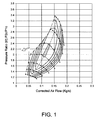
- Figure 1 displays the working range of a specific turbo compressor.
- the working range of the compressor is readable from the pressure ratio P2c/P1c on the vertical axis and the air mass flow through the compressor on the horisontal axis, where P2c is the pressure downstream of the compressor and P1c is the pressure upstream of the compressor.
- P2c is the pressure downstream of the compressor
- P1c is the pressure upstream of the compressor.
- a pre-whirl in the same direction as the compressor impeller's rotational direction will shift the compressor map towards lower mass flow rates and lower compressor pressure ratio as indicated by the arrow in Figure 1. This means that the compressor would get the character of a down sized one in that the working range of the compressor is extended to lower mass flow rates.
- map shift depends on the magnitude of the pre-whirl and the impeller blade angle (degree of back sweeping).
- a way to provide a pre-whirl and thereby achieve an extended compressor map is to provide guide vanes in an air duct upstream of the compressor.
- a turbo charged marine diesel engine with guide vanes for preventing turbo overspeed and surging is known from GB 2172340.
- a drawback of this solution is that guide vanes to a certain degree restrict the flow of air through the duct. This flow restriction is unfavourable regarding engine performance at high air flow rates.
- An object of the invention is to provide a supercharged internal combustion engine in which pre-whirl can be generated at low inlet air flow speeds, and in which the flow resistance at high flow speeds is reduced, as compared to the guide vane solution described above.
- Another object of present invention is to provide a supercharged internal combustion engine that is improved in respect of pre-whirl control as well as in respect of engine power and torque performance.
- a further object of the invention is to provide a supercharged internal combustion engine with increased reliability of supercharging efficiency.
- Still a further object of the invention is to provide a supercharged internal combustion engine that is more fuel efficient and that exhausts less unhealthy emissions.
- a supercharged internal combustion engine comprising a compressor impeller for increasing pressure of a gas mixture to be combusted in said engine, and a first duct for supplying said gas mixture to said compressor impeller, said engine further comprising a second duct for supplying additional gas mixture into the first duct at a connection upstream of said compressor impeller.
- the present invention provides a supercharged internal combustion engine further comprising a volute at the connection between the two ducts and one valve inside each of the two ducts for controlling gas flow through the ducts.
- Another object of the invention is to provide an improved method for controlling pre-whirl in a supercharged internal combustion engine.
- This object is attained by a method for controlling a supercharged internal combustion engine comprising a compressor impeller for increasing pressure of a gas mixture to be combusted in said engine, wherein said gas mixture is supplied to said compressor impeller via first and second ducts, and generating a pre-whirl in the gas mixture supplied to said compressor impeller upstream of said compressor impeller.
- the inventive method further comprises the following steps for controlling the pre-whirl:
- the invention is especially useful for turbocharged diesel engines. This is due to the fact that the exhaust gases of diesel engines are relatively colder than exhaust gases from petrol engines, and that so called variable nozzles are sensitive to high temperatures. Colder exhaust gases give an opportunity to use a variable nozzle at the exhaust turbine and thereby increase the working range of the exhaust turbine. Therefore it is also desirable to extend the working range of the compressor impeller in order to get the most effect out of the extended working range of the turbine.
- the working range of the exhaust turbine can be extended by means of a fairly temperature sensitive variable nozzle as mentioned by way of introduction.
- the working range of the turbocharger is in this case restricted by the compressor impeller's working range, which can be extended by generating a pre-whirl according to the invention.
- the invention can also be implemented in a turbocharged petrol engine with a highly temperature resistant variable nozzle turbine.
- a main throttle downstream of the compressor of the petrol engine can be arranged conventionally.
- the main throttle can be excluded and the throttling function can be performed by valves (36,38 described below) upstream of the compressor.
- a third duct similar to the second duct can also be communicatingly connected to the first duct via a volute arranged for generating a negative pre-whirl.
- the second duct is preferably connected to the first duct via a volute arranged for generating a positive pre-whirl. Control of the pre-whirl direction can then be facilitated by adjustment of valves in first, second and third ducts.
- the invention is directed to a supercharged internal combustion engine in which the supercharging is provided by a compressor impeller.
- Said compressor impeller can for example be driven by an electric motor or mechanically via a crankshaft of the engine or from an exhaust turbine, the latter case known as turbo charging.
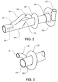
- Figure 2 shows a compressor 20 with an outlet 22 for providing compressed air to the combustion chambers of the engine and an inlet 24 for receiving ambient air via an air filter (not shown).
- the air flow direction is indicated by an arrow 26.
- First duct 28 constitutes a main flow path for the air flow
- second duct 30 is connected to first duct 28 at a first connection.
- the first connection comprises a volute 32 so that a flow through second duct 30 contributes to a positive pre-whirl of the air entering into compressor 20.
- the pre-whirl is in this example generally a rotational motion of air around a center axis of first duct 28 combined with a translation of the air in the longitudinal direction of the first duct 28.
- all of the engine air is provided via the air filter of first duct 28.
- the second duct 30 is then fed by a portion of the air flow from first duct 28 at a second connection 34 between the two ducts upstream of the first connection at the volute 32.
- the first or the second or both ducts are provided with valves, a first valve 36 in first duct 28 and/or a second valve 38 in second duct 30.
- a first valve 36 in first duct 28 By adjusting the valves 36,38 the distribution of the air flow between the two ducts can be effectively controlled.
- An advantage of the two-valve solution is that the flow adjustment possibilities provide a larger range for the pre-whirl magnitude.
- a solution with a valve 38 in second duct 30 and no valve in first duct 28 may be more advantageous for high engine performance reasons since it eliminates from first duct 28 the flow resistance that a valve represents even in its fully open position.
- Valves 36 and 38 are preferably designed as butterfly valves which can be actuated via a variety of actuation means. For example, they can be actuated by electric motors which are controlled by signals from the vehicle's engine control computer.
- Valve 38 is initially fully open and the air flow is initially directed to the compressor impeller through second duct 30, while the valve 36 is substantially closed. As the mass flow increases and the brake torque approaches maximum, the valve 38 is gradually closed and the valve 36 is opened towards its fully open position. This means that the compressor virtual size is adapted to the mass flow rate during the low end period.
- An advantage of using a volute instead of putting pre-whirl guide vanes in front of the compressor impeller is a reduced flow resistance in first duct 28 since guide vanes in ducts represent a flow resistance. This advantage result in improved high performance properties of the engine.
- Figure 3 shows another embodiment of the invention in which first and second ducts 28,30 are arranged as ducts with individual air filters and connected to each other only at the volute 32. There is no second connection between the two ducts 28,30 in this embodiment.
- the end 29 of first duct 28 leads to an air filter (not shown), while the end 31 of second duct 30 leads to another air filter (not shown).
- An advantage of this embodiment is that the flow resistance is reduced since there is one connection less between the two ducts 28,30.
- the additional gas mixture is supplied from said second duct 30 into said first duct 28 in a substantially tangential manner for generating a pre-whirl in said first duct 28.
- the substantially tangential gas mixture supply is provided for by means of the volute 32.
- a substantially tangential gas mixture supply e.g. a simple angled connection between the ducts 28,30.
- Figure 4 shows in a schematic view an arrangement with a volute 32 and a compressor impeller 50 with back swept blades 52.
- the degree of back sweeping of the blades 52 is between 40° and 45°.
Landscapes
- Engineering & Computer Science (AREA)
- Mechanical Engineering (AREA)
- General Engineering & Computer Science (AREA)
- Chemical & Material Sciences (AREA)
- Combustion & Propulsion (AREA)
- Chemical Kinetics & Catalysis (AREA)
- General Chemical & Material Sciences (AREA)
- Supercharger (AREA)
Abstract
Description
- The invention relates to a supercharged internal combustion engine comprising a compressor impeller and a duct arranged for generation of pre-whirl of air supplied to the compressor impeller. The invention also relates to a method for controlling a supercharged internal combustion engine.
- In turbo charged engines, the low end torque is limited by the exhaust gas enthalpy and the surge line of compressors. A variable nozzle turbine can be used to maximise the turbine efficiency and hence the power output from the exhaust gas flow at various engine speeds and loads. This can result in an improved low end torque compared to the same engine running with waste gated turbo charger. However, the size of the compressor, which is often stipulated by the engine rated power, will still limit the low-end torque.
- By applying a pre-rotating flow (pre-whirl) into the compressor, the characteristics of the compressor will be changed. Figure 1 displays the working range of a specific turbo compressor. The working range of the compressor is readable from the pressure ratio P2c/P1c on the vertical axis and the air mass flow through the compressor on the horisontal axis, where P2c is the pressure downstream of the compressor and P1c is the pressure upstream of the compressor. A pre-whirl in the same direction as the compressor impeller's rotational direction will shift the compressor map towards lower mass flow rates and lower compressor pressure ratio as indicated by the arrow in Figure 1. This means that the compressor would get the character of a down sized one in that the working range of the compressor is extended to lower mass flow rates. The significance of the map shift depends on the magnitude of the pre-whirl and the impeller blade angle (degree of back sweeping). By applying the required pre-whirl to a correctly designed compressor it is possible to achieve good pressure ratios at flow rates below the compressors inherent surge line.
- A way to provide a pre-whirl and thereby achieve an extended compressor map is to provide guide vanes in an air duct upstream of the compressor. For example, a turbo charged marine diesel engine with guide vanes for preventing turbo overspeed and surging is known from GB 2172340. A drawback of this solution is that guide vanes to a certain degree restrict the flow of air through the duct. This flow restriction is unfavourable regarding engine performance at high air flow rates.
- An object of the invention is to provide a supercharged internal combustion engine in which pre-whirl can be generated at low inlet air flow speeds, and in which the flow resistance at high flow speeds is reduced, as compared to the guide vane solution described above.
- Another object of present invention is to provide a supercharged internal combustion engine that is improved in respect of pre-whirl control as well as in respect of engine power and torque performance.
- A further object of the invention is to provide a supercharged internal combustion engine with increased reliability of supercharging efficiency.
- Still a further object of the invention is to provide a supercharged internal combustion engine that is more fuel efficient and that exhausts less unhealthy emissions.
- These objects are attained by a supercharged internal combustion engine comprising a compressor impeller for increasing pressure of a gas mixture to be combusted in said engine, and a first duct for supplying said gas mixture to said compressor impeller, said engine further comprising a second duct for supplying additional gas mixture into the first duct at a connection upstream of said compressor impeller.
- In particular, the present invention provides a supercharged internal combustion engine further comprising a volute at the connection between the two ducts and one valve inside each of the two ducts for controlling gas flow through the ducts.
- Another object of the invention is to provide an improved method for controlling pre-whirl in a supercharged internal combustion engine.
- This object is attained by a method for controlling a supercharged internal combustion engine comprising a compressor impeller for increasing pressure of a gas mixture to be combusted in said engine, wherein said gas mixture is supplied to said compressor impeller via first and second ducts, and generating a pre-whirl in the gas mixture supplied to said compressor impeller upstream of said compressor impeller.
- In particular, during acceleration of a vehicle propelled by said engine, the inventive method further comprises the following steps for controlling the pre-whirl:
- at low engine speeds controlling a valve in the second duct to be open and a valve in the first duct to be substatially closed,
- as the engine speed increases successively opening the valve in the first duct and succesively closing the valve in the second duct.
- That is, when the engine is running at low speed a positve pre-whirl is generated. Later in the acceleration, when the engine is running at a higher speed, no pre-whirl is generated, but instead a minimised flow resistance in the first air duct is achieved.
- The invention is especially useful for turbocharged diesel engines. This is due to the fact that the exhaust gases of diesel engines are relatively colder than exhaust gases from petrol engines, and that so called variable nozzles are sensitive to high temperatures. Colder exhaust gases give an opportunity to use a variable nozzle at the exhaust turbine and thereby increase the working range of the exhaust turbine. Therefore it is also desirable to extend the working range of the compressor impeller in order to get the most effect out of the extended working range of the turbine.
- In other words, the working range of the exhaust turbine can be extended by means of a fairly temperature sensitive variable nozzle as mentioned by way of introduction. Hence, the working range of the turbocharger is in this case restricted by the compressor impeller's working range, which can be extended by generating a pre-whirl according to the invention.
- The invention can also be implemented in a turbocharged petrol engine with a highly temperature resistant variable nozzle turbine. A main throttle downstream of the compressor of the petrol engine can be arranged conventionally. Alternatively, the main throttle can be excluded and the throttling function can be performed by valves (36,38 described below) upstream of the compressor.
- In case of a applying a negative pre-whirl, where the pre-whirl direction is opposite to the compressor impeller rotation, the result will be a compressor map shift in the opposite direction. In order to provide both positive and negative pre-whirl in the same engine a third duct similar to the second duct can also be communicatingly connected to the first duct via a volute arranged for generating a negative pre-whirl. The second duct is preferably connected to the first duct via a volute arranged for generating a positive pre-whirl. Control of the pre-whirl direction can then be facilitated by adjustment of valves in first, second and third ducts.
-
- Figure 1 shows an example of a compressor map or working range of a compressor impeller of a supercharged engine.
- Figure 2 shows, schematically, the ducts leading to a compressor according to an embodiment of the invention.
- Figure 3 shows, schematically, the ducts leading to a compressor according to another embodiment of the invention.
- Figure 4 shows, scematically, the arrangement of a compressor impeller and a volute according to an embodiment of the invention.
-
- The invention is directed to a supercharged internal combustion engine in which the supercharging is provided by a compressor impeller. Said compressor impeller can for example be driven by an electric motor or mechanically via a crankshaft of the engine or from an exhaust turbine, the latter case known as turbo charging.
- Figure 2 shows a
compressor 20 with anoutlet 22 for providing compressed air to the combustion chambers of the engine and aninlet 24 for receiving ambient air via an air filter (not shown). The air flow direction is indicated by anarrow 26. Between the air filter and the compressor inlet 24 afirst duct 28 and asecond duct 30 are provided.First duct 28 constitutes a main flow path for the air flow, whilesecond duct 30 is connected tofirst duct 28 at a first connection. At the connection air from thesecond duct 30 is supplied in a substantially tangential manner intofirst duct 28. For this purpose the first connection comprises avolute 32 so that a flow throughsecond duct 30 contributes to a positive pre-whirl of the air entering intocompressor 20. The pre-whirl is in this example generally a rotational motion of air around a center axis offirst duct 28 combined with a translation of the air in the longitudinal direction of thefirst duct 28. In this case all of the engine air is provided via the air filter offirst duct 28. Thesecond duct 30 is then fed by a portion of the air flow fromfirst duct 28 at asecond connection 34 between the two ducts upstream of the first connection at thevolute 32. - To control the magnitude and significance of the pre-whirl depending upon engine speed and load, the first or the second or both ducts are provided with valves, a
first valve 36 infirst duct 28 and/or asecond valve 38 insecond duct 30. By adjusting thevalves valve 38 insecond duct 30 and no valve infirst duct 28 may be more advantageous for high engine performance reasons since it eliminates fromfirst duct 28 the flow resistance that a valve represents even in its fully open position. -
Valves - An example of the control strategy can be described as follows.
Valve 38 is initially fully open and the air flow is initially directed to the compressor impeller throughsecond duct 30, while thevalve 36 is substantially closed. As the mass flow increases and the brake torque approaches maximum, thevalve 38 is gradually closed and thevalve 36 is opened towards its fully open position. This means that the compressor virtual size is adapted to the mass flow rate during the low end period. - An advantage of using a volute instead of putting pre-whirl guide vanes in front of the compressor impeller is a reduced flow resistance in
first duct 28 since guide vanes in ducts represent a flow resistance. This advantage result in improved high performance properties of the engine. - Figure 3 shows another embodiment of the invention in which first and
second ducts volute 32. There is no second connection between the twoducts end 29 offirst duct 28 leads to an air filter (not shown), while theend 31 ofsecond duct 30 leads to another air filter (not shown). An advantage of this embodiment is that the flow resistance is reduced since there is one connection less between the twoducts - In the embodiments according to Fig 2 and 3, the additional gas mixture is supplied from said
second duct 30 into saidfirst duct 28 in a substantially tangential manner for generating a pre-whirl in saidfirst duct 28. In these embodiments the substantially tangential gas mixture supply is provided for by means of thevolute 32. There are however also other possibilities to provide a substantially tangential gas mixture supply, e.g. a simple angled connection between theducts - Figure 4 shows in a schematic view an arrangement with a
volute 32 and acompressor impeller 50 with back sweptblades 52. Preferably, the degree of back sweeping of theblades 52 is between 40° and 45°. - The invention is not restricted to the described embodiments but can be varied within the scope of the appended patent claims.
Claims (13)
- A supercharged internal combustion engine comprising a compressor impeller (50) for increasing pressure of a gas mixture to be combusted in said engine, and a first duct (28) for supplying said gas mixture to said compressor impeller (50), characterized in that the engine further comprises a second duct (30) for supplying additional gas mixture into the first duct (28) at a connection upstream of said compressor impeller (50).
- An engine according to claim 1, characterized in that the additional gas mixture is supplied from said second duct (30) into said first duct (28) in a substantially tangential manner for generating a pre-whirl in said first duct (28).
- An engine according to claim 1 or 2, characterized in that said connection between first and second ducts (28,30) comprises a volute (32).
- An engine according to any one of the preceding claims, characterized in that a valve (36) is arranged inside said first duct (28), for control of the flow of gas mixture through said first duct (28).
- An engine according to any one of the preceding claims, characterized in that a valve (38) is arranged inside said second duct (30), for control of the flow of said additional gas mixture through said second duct (30).
- An engine according to any one of the preceding claims, characterized in that said first duct (28) is connected to a first air filter and said second duct (30) is connected to a second air filter.
- An engine according to any one of claims 1-5, characterized in that said first duct (28) is connected to an air filter, and in that the second duct (30) branches from the first duct (28) upstream of said connection.
- An engine according to any one of the preceding claims, characterized in that said compressor impeller (50) is drivingly connected to an exhaust turbine.
- A method for controlling a supercharged internal combustion engine comprising a compressor impeller (50) for increasing pressure of a gas mixture to be combusted in said engine, wherein said gas mixture is supplied to said compressor impeller (50) via first and second ducts (28,30), the method comprising the step of generating a pre-whirl in the gas mixture supplied to said compressor impeller (50) upstream of said compressor impeller (50).
- A method according to claim 9, characterized in supplying gas mixture from said second duct (30) into said first duct (28) in a substantially tangential manner.
- A method according to claim 9 or 10, characterized in controlling the pre-whirl in the gas mixture supplied to the impeller (50) by means of a first valve (36) in said first duct (28).
- A method according to any one of claims 9-11, characterized in controlling the pre-whirl in the gas mixture supplied to the impeller (50) by means of a second valve (38) in said second duct (30).
- A method according to claim 12, characterized in that during acceleration of a vehicle propelled by said engine, said pre-whirl is controlled by the following steps:at low engine speeds controlling said second valve (38) to be open and said first valve (36) to be substatially closed,as the engine speed increases successively opening said first valve (36) and succesively closing said second valve (38).
Priority Applications (2)
| Application Number | Priority Date | Filing Date | Title |
|---|---|---|---|
| EP03012017A EP1482128B1 (en) | 2003-05-28 | 2003-05-28 | Supercharged Internal combustion engine |
| DE60309003T DE60309003T2 (en) | 2003-05-28 | 2003-05-28 | Charged combustion engine |
Applications Claiming Priority (1)
| Application Number | Priority Date | Filing Date | Title |
|---|---|---|---|
| EP03012017A EP1482128B1 (en) | 2003-05-28 | 2003-05-28 | Supercharged Internal combustion engine |
Publications (2)
| Publication Number | Publication Date |
|---|---|
| EP1482128A1 true EP1482128A1 (en) | 2004-12-01 |
| EP1482128B1 EP1482128B1 (en) | 2006-10-11 |
Family
ID=33104093
Family Applications (1)
| Application Number | Title | Priority Date | Filing Date |
|---|---|---|---|
| EP03012017A Expired - Lifetime EP1482128B1 (en) | 2003-05-28 | 2003-05-28 | Supercharged Internal combustion engine |
Country Status (2)
| Country | Link |
|---|---|
| EP (1) | EP1482128B1 (en) |
| DE (1) | DE60309003T2 (en) |
Cited By (8)
| Publication number | Priority date | Publication date | Assignee | Title |
|---|---|---|---|---|
| FR2878914A1 (en) * | 2004-12-03 | 2006-06-09 | Inst Francais Du Petrole | AIR COMPRESSOR, ESPECIALLY FOR AN INTERNAL COMBUSTION ENGINE, INCLUDING AN ADJUSTED AIR ROTATION CHAMBER |
| DE102005023647A1 (en) * | 2005-05-21 | 2006-11-23 | Daimlerchrysler Ag | Exhaust gas turbocharger for e.g. petrol engine, has smoothing chamber flow conditioning of air that flows to compressor, where longitudinal axis of inflow channel is inclined at angle opposite to longitudinal axis of chamber |
| NL1029313C2 (en) * | 2005-06-22 | 2006-12-27 | Innosource B V | Air exhaust device. |
| EP2067958A3 (en) * | 2007-12-04 | 2009-11-25 | Mann+Hummel Gmbh | Exhaust gas turbocharger for a combustion engine and device to switch an air guidance device of an exhaust gas turbocharger |
| US7874789B2 (en) | 2007-04-06 | 2011-01-25 | Honeywell International, Inc. | Compressor and compressor housing |
| GB2490563A (en) * | 2011-05-03 | 2012-11-07 | Peter John Bayram | Pre-rotating or de-rotating fluid flow with a volute |
| CN104832928A (en) * | 2015-05-22 | 2015-08-12 | 遵义市节庆机电有限责任公司 | Methane combustion device |
| US11149665B2 (en) | 2017-05-31 | 2021-10-19 | Volvo Truck Corporation | Method and system for controlling engine derating |
Families Citing this family (1)
| Publication number | Priority date | Publication date | Assignee | Title |
|---|---|---|---|---|
| DE102008004746A1 (en) * | 2008-01-16 | 2009-07-23 | Behr Gmbh & Co. Kg | Blower, in particular for the fresh and / or Umluftansaugung a vehicle air conditioning |
Citations (6)
| Publication number | Priority date | Publication date | Assignee | Title |
|---|---|---|---|---|
| US4250711A (en) * | 1975-08-29 | 1981-02-17 | Bbc Brown, Boveri & Company, Limited | Method and apparatus for supercharging an internal combustion engine |
| US4756161A (en) * | 1984-02-29 | 1988-07-12 | Nissan Motor Co., Ltd. | Controller for variable geometry type turbocharger |
| US5236301A (en) * | 1991-12-23 | 1993-08-17 | Allied-Signal Inc. | Centrifugal compressor |
| DE4213047A1 (en) * | 1992-04-21 | 1993-10-28 | Kuehnle Kopp Kausch Ag | Radial compressor for vehicle exhaust gas turbocharger - uses feed pipe to deliver flow medium to influence conditions in circulation chamber |
| US5863178A (en) * | 1996-11-18 | 1999-01-26 | Daimler-Benz Ag | Exhaust turbocharger for internal combustion engines |
| US6357234B1 (en) * | 2000-09-21 | 2002-03-19 | Caterpillar Inc. | Turbocharger system with turbines having independently controlled variable nozzles |
-
2003
- 2003-05-28 DE DE60309003T patent/DE60309003T2/en not_active Expired - Lifetime
- 2003-05-28 EP EP03012017A patent/EP1482128B1/en not_active Expired - Lifetime
Patent Citations (6)
| Publication number | Priority date | Publication date | Assignee | Title |
|---|---|---|---|---|
| US4250711A (en) * | 1975-08-29 | 1981-02-17 | Bbc Brown, Boveri & Company, Limited | Method and apparatus for supercharging an internal combustion engine |
| US4756161A (en) * | 1984-02-29 | 1988-07-12 | Nissan Motor Co., Ltd. | Controller for variable geometry type turbocharger |
| US5236301A (en) * | 1991-12-23 | 1993-08-17 | Allied-Signal Inc. | Centrifugal compressor |
| DE4213047A1 (en) * | 1992-04-21 | 1993-10-28 | Kuehnle Kopp Kausch Ag | Radial compressor for vehicle exhaust gas turbocharger - uses feed pipe to deliver flow medium to influence conditions in circulation chamber |
| US5863178A (en) * | 1996-11-18 | 1999-01-26 | Daimler-Benz Ag | Exhaust turbocharger for internal combustion engines |
| US6357234B1 (en) * | 2000-09-21 | 2002-03-19 | Caterpillar Inc. | Turbocharger system with turbines having independently controlled variable nozzles |
Cited By (11)
| Publication number | Priority date | Publication date | Assignee | Title |
|---|---|---|---|---|
| FR2878914A1 (en) * | 2004-12-03 | 2006-06-09 | Inst Francais Du Petrole | AIR COMPRESSOR, ESPECIALLY FOR AN INTERNAL COMBUSTION ENGINE, INCLUDING AN ADJUSTED AIR ROTATION CHAMBER |
| DE102005023647A1 (en) * | 2005-05-21 | 2006-11-23 | Daimlerchrysler Ag | Exhaust gas turbocharger for e.g. petrol engine, has smoothing chamber flow conditioning of air that flows to compressor, where longitudinal axis of inflow channel is inclined at angle opposite to longitudinal axis of chamber |
| DE102005023647B4 (en) * | 2005-05-21 | 2014-09-04 | Daimler Ag | Exhaust gas turbocharger with a compressor |
| NL1029313C2 (en) * | 2005-06-22 | 2006-12-27 | Innosource B V | Air exhaust device. |
| US7874789B2 (en) | 2007-04-06 | 2011-01-25 | Honeywell International, Inc. | Compressor and compressor housing |
| EP2067958A3 (en) * | 2007-12-04 | 2009-11-25 | Mann+Hummel Gmbh | Exhaust gas turbocharger for a combustion engine and device to switch an air guidance device of an exhaust gas turbocharger |
| US8156741B2 (en) | 2007-12-04 | 2012-04-17 | Mann + Hummel Gmbh | Exhaust gas turbocharger for an internal combustion engine and device for switching an air guiding device of an exhaust gas turbocharger |
| GB2490563A (en) * | 2011-05-03 | 2012-11-07 | Peter John Bayram | Pre-rotating or de-rotating fluid flow with a volute |
| GB2490563B (en) * | 2011-05-03 | 2015-07-22 | Peter John Bayram | Spiral energy recovery and flow pre-rotation for turbochargers, turbo-expansion valves, turbojets and marine propellers, etc |
| CN104832928A (en) * | 2015-05-22 | 2015-08-12 | 遵义市节庆机电有限责任公司 | Methane combustion device |
| US11149665B2 (en) | 2017-05-31 | 2021-10-19 | Volvo Truck Corporation | Method and system for controlling engine derating |
Also Published As
| Publication number | Publication date |
|---|---|
| DE60309003T2 (en) | 2007-05-24 |
| DE60309003D1 (en) | 2006-11-23 |
| EP1482128B1 (en) | 2006-10-11 |
Similar Documents
| Publication | Publication Date | Title |
|---|---|---|
| CN105464789B (en) | Twin-scroll turbocharger device for internal combustion engine and control method thereof | |
| US7644585B2 (en) | Multi-stage turbocharging system with efficient bypass | |
| US8522547B2 (en) | Exhaust gas turbocharger for an internal combustion engine of a motor vehicle | |
| CN101842565B (en) | With the internal combustion engine of exhaust-driven turbo-charger exhaust-gas turbo charger and charger-air cooler | |
| JP4680472B2 (en) | Internal combustion engine-turbosupercharger unit for motor vehicles with turbine power control, in particular industrial vehicles | |
| US10526955B2 (en) | Supercharging device for an internal combustion engine, and operating method for the supercharging device | |
| US6378305B1 (en) | Internal combustion engine having an exhaust-gas turbocharger and a method for operating same | |
| JP2019044777A5 (en) | ||
| JP2006097684A (en) | Multi-stage turbocharger using VTG turbine stage | |
| JPS5996434A (en) | Internal combustion engne | |
| CN105569825B (en) | Diesel engine flexibility supercharging control method | |
| CN104343528A (en) | Turbocharging system | |
| CN106795805A (en) | Supercharging equipment for explosive motor and the operating method for supercharging equipment | |
| JPH07293262A (en) | Sequential supercharger for diesel engine | |
| US20120159948A1 (en) | Internal combustion engine with supercharger | |
| US20130309106A1 (en) | Turbocharger | |
| US20030115870A1 (en) | Exhaust-gas turbocharger in an internal combustion engine | |
| JPS5982526A (en) | Supercharger for internal-combustion engine | |
| EP1482128B1 (en) | Supercharged Internal combustion engine | |
| Uchida | Transient performance prediction for turbocharging systems incorporating variable-geometry turbochargers | |
| JPS6050980B2 (en) | Exhaust gas recirculation device for exhaust turbocharged engines | |
| JPS58200031A (en) | Internal-combustion engine supercharged by exhaust turbo | |
| CN106870176B (en) | Method for operating a drive system for a motor vehicle and corresponding drive system | |
| KR20210064637A (en) | Apparatus for Reducing the Surge of Engine having Turbo-charge | |
| KR20080090320A (en) | Parallel turbocharger system |
Legal Events
| Date | Code | Title | Description |
|---|---|---|---|
| REG | Reference to a national code |
Ref country code: SE Ref legal event code: TRGR |
|
| PUAI | Public reference made under article 153(3) epc to a published international application that has entered the european phase |
Free format text: ORIGINAL CODE: 0009012 |
|
| AK | Designated contracting states |
Kind code of ref document: A1 Designated state(s): AT BE BG CH CY CZ DE DK EE ES FI FR GB GR HU IE IT LI LU MC NL PT RO SE SI SK TR |
|
| AX | Request for extension of the european patent |
Extension state: AL LT LV MK |
|
| 17P | Request for examination filed |
Effective date: 20050601 |
|
| 17Q | First examination report despatched |
Effective date: 20050628 |
|
| AKX | Designation fees paid |
Designated state(s): DE GB SE |
|
| GRAP | Despatch of communication of intention to grant a patent |
Free format text: ORIGINAL CODE: EPIDOSNIGR1 |
|
| RAP1 | Party data changed (applicant data changed or rights of an application transferred) |
Owner name: FORD GLOBAL TECHNOLOGIES, LLC. |
|
| GRAS | Grant fee paid |
Free format text: ORIGINAL CODE: EPIDOSNIGR3 |
|
| GRAA | (expected) grant |
Free format text: ORIGINAL CODE: 0009210 |
|
| AK | Designated contracting states |
Kind code of ref document: B1 Designated state(s): DE GB SE |
|
| REG | Reference to a national code |
Ref country code: GB Ref legal event code: FG4D |
|
| REF | Corresponds to: |
Ref document number: 60309003 Country of ref document: DE Date of ref document: 20061123 Kind code of ref document: P |
|
| PLBE | No opposition filed within time limit |
Free format text: ORIGINAL CODE: 0009261 |
|
| STAA | Information on the status of an ep patent application or granted ep patent |
Free format text: STATUS: NO OPPOSITION FILED WITHIN TIME LIMIT |
|
| 26N | No opposition filed |
Effective date: 20070712 |
|
| PGFP | Annual fee paid to national office [announced via postgrant information from national office to epo] |
Ref country code: SE Payment date: 20110419 Year of fee payment: 9 |
|
| PGFP | Annual fee paid to national office [announced via postgrant information from national office to epo] |
Ref country code: GB Payment date: 20110419 Year of fee payment: 9 |
|
| PGFP | Annual fee paid to national office [announced via postgrant information from national office to epo] |
Ref country code: DE Payment date: 20110428 Year of fee payment: 9 |
|
| REG | Reference to a national code |
Ref country code: GB Ref legal event code: 732E Free format text: REGISTERED BETWEEN 20111020 AND 20111025 |
|
| REG | Reference to a national code |
Ref country code: DE Ref legal event code: R081 Ref document number: 60309003 Country of ref document: DE Owner name: VOLVO CAR CORPORATION, SE Free format text: FORMER OWNER: FORD GLOBAL TECHNOLOGIES, LLC, DEARBORN, US Effective date: 20120207 Ref country code: DE Ref legal event code: R081 Ref document number: 60309003 Country of ref document: DE Owner name: VOLVO CAR CORPORATION, SE Free format text: FORMER OWNER: FORD GLOBAL TECHNOLOGIES, LLC, DEARBORN, MICH., US Effective date: 20120207 |
|
| REG | Reference to a national code |
Ref country code: SE Ref legal event code: EUG |
|
| GBPC | Gb: european patent ceased through non-payment of renewal fee |
Effective date: 20120528 |
|
| PG25 | Lapsed in a contracting state [announced via postgrant information from national office to epo] |
Ref country code: SE Free format text: LAPSE BECAUSE OF NON-PAYMENT OF DUE FEES Effective date: 20120529 |
|
| REG | Reference to a national code |
Ref country code: DE Ref legal event code: R119 Ref document number: 60309003 Country of ref document: DE Effective date: 20121201 |
|
| PG25 | Lapsed in a contracting state [announced via postgrant information from national office to epo] |
Ref country code: GB Free format text: LAPSE BECAUSE OF NON-PAYMENT OF DUE FEES Effective date: 20120528 |
|
| PG25 | Lapsed in a contracting state [announced via postgrant information from national office to epo] |
Ref country code: DE Free format text: LAPSE BECAUSE OF NON-PAYMENT OF DUE FEES Effective date: 20121201 |