TECHNICAL FIELD
The present invention relates to a MgO vapor deposition material and a
production process for such a material, and relates particularly to technology that is ideal
for generating the MgO film of an AC type plasma display panel or the like.
BACKGROUND ART
Because MgO displays excellent heat resistance, conventionally it has been used
mainly as a heat resistant material for crucibles and fire bricks and the like, and various
techniques have been proposed for improving the mechanical strength, including the
addition of sintering assistants. Examples of known techniques include those disclosed
in the patent references 1 to 3.
As follows is a list of references.
In recent years, the research, development, and implementation of flat panel
displays, including liquid crystal displays (LCD) has been remarkable, and the
production of these displays is increasing rapidly. The development and introduction of
color plasma display panels (PDP) has also surged recently. PDPs can be easily
produced in very large sizes, and represent the most promising technology for producing
a high definition, wall-mounted large screen television. Tests and production of PDPs
with a diagonal size in the 60 inch range are already in progress, and of the different PDP
technologies, AC type display panels in which the electrode construction utilizes a metal
electrode covered with a glass dielectric material are the most common.
In these AC type PDPs, the surface of the glass dielectric layer is coated with a
protective film that displays a high heat of sublimation, in order to prevent the ion
bombardment sputtering from altering the surface of the glass dielectric layer and raising
the breakdown voltage. Because it contacts the discharge gas directly, this protective
film must not only be resistant to sputtering, but must also perform a plurality of other
important roles. Namely, the properties required of this protective film include resistance
to sputtering during discharge, a high secondary emission capability (a low discharge
voltage), as well as good insulation and light transmittance. MgO films produced by
either electron beam deposition or ion plating using MgO as the vapor deposition
material are typically used as the material for satisfying these property requirements. As
described above, these MgO protective films perform an important role in extending the
life of the PDP by protecting the surface of the dielectric layer from the sputtering during
discharge, and it is known that increasing the film density of this protective film enables
an improvement in the sputtering resistance (non-patent reference 1).
In addition, both single crystal MgO and polycrystalline MgO have been used for
this protective film (vapor deposition material). Technology relating to this protective
film includes that disclosed in the patent references 6 to 11 listed above.
Furthermore, in a technique disclosed in the patent reference 4, the secondary
emission efficiency of the protective film is improved, and display performance problems
such as breakdown delay within the light emitting cells and faults within the write
operation can be improved, by reducing the electronegative element component such as
sulfur within the protective film.
The method used for removing the electronegative element component such as
sulfur requires a heat treatment at a temperature of at least 1400°C in either a vacuum
with a pressure of no more than 1.33×10⁻¹ Pa (10-3 Torr) or in an oxygen containing
atmosphere, which is performed following crystal growth (pellet preparation) and prior to
formation of the protective film, although in the case of polycrystals or single crystals
produced using an electromelting method with a relative density of at least 90%, the
efficiency of the sulfur removal was poor.
The polycrystalline MgO described above is typically produced by granulating,
molding and baking an MgO powder of arbitrary purity and with an arbitrary impurities
composition produced by either a sea water method or a vapor phase method. In contrast,
single crystal MgO is typically produced by melting MgO clinker or light burned MgO
(baked at a temperature of no more than 1000°C) with a purity of at least 98% in an
electric arc furnace, that is forming an ingot by electromelting, and then extracting single
crystal portions from this ingot and crushing the product. The MgO powder, MgO
clinker, or light burned MgO used as the raw material for producing these products
typically comprises a sulfur S component, a chlorine Cl component, a nitrogen N
component and a phosphorus P component and the like as impurities, due to the
production methods employed and the intrinsic reactivity of MgO.
It is known that during film formation using either an electron beam deposition
method or an ion plating method, the quantities of sulfur S, chlorine Cl, nitrogen N and
phosphorus P discharged from the MgO vapor deposition material as impurities has a
deleterious effect on the level of splash associated with that vapor deposition material. In
other words, as the quantities of sulfur S, chlorine Cl, nitrogen N and phosphorus P
impurities increase, the level of splash also increases, and if the level of splash is high,
then the degree of efficiency with which the quantity of vapor deposition material can be
used in the film formation process decreases, resulting in an increase in material costs.
In addition, if the quantities of sulfur S, chlorine Cl, nitrogen N and phosphorus P
impurities are high, then control of the crystal orientation and microstructure of the
product film becomes difficult, and compact deposition of the MgO film onto the
substrate is inhibited, meaning the film density tends to decrease. If the density of the
MgO film decreases, then various problems can arise including a reduction in the
refractive index, a deterioration in the sputtering resistance, and deterioration in both the
discharge characteristics and the insulating characteristics.
In terms of the target material used in the sputtering method, the type of
technology disclosed in the patent reference 12 described above is already known.
When preparing a target material for use in a sputtering method, this target
material must be produced with as high a density as possible. In contrast, the inventors
of the present invention have confirmed that when preparing a vapor deposition material
for use in an electron beam deposition method, the density required of the vapor
deposition material need not be as precise in terms of the measurement of degassing from
the vapor deposition material and the evaluation of the film formation, and the allowable
density range for the vapor deposition material is comparatively broad.
Furthermore, the target material and the vapor deposition material are not
significantly different in terms of their microstructures, but are very different in macro
terms.
Namely, in a sputtering method, the target material is formed as a comparatively
large plate such as a circular or angular plate, whereas in an electron beam deposition
method, the vapor deposition material is formed as small pellets. In a sputtering method,
in which positive ions such as argon cause knock-on at the atomic level of the target
material, which functions as the film formation material, thereby depositing this film
formation material on a substrate, the reason that the target material is formed as a plate
that is comparatively larger than the substrate or the like on which the film is to be
formed, is to ensure a more uniform distribution of the thickness of the film produced
from the target material.
In contrast, in an electron beam deposition method, in which a material is
deposited on a substrate by heating and subsequent conversion to a vapor state using an
electron beam, the reason that the vapor deposition material is formed as small pellets is
to enable the vapor deposition material to be supplied sequentially to the crucible of the
electron beam deposition apparatus. Furthermore, in an electron beam deposition method,
because of the so-called splash phenomenon peculiar to electron beam deposition and
from the viewpoint of film formation speed, an optimum size exists for the vapor
deposition process.
Because the film formation mechanisms for sputtering methods and electron
beam deposition methods differ in this manner, the film formation conditions are
completely different, and the quality of the product films is also different. Namely, in a
sputtering method the composition of the product film varies depending on how easily
the target material undergoes sputtering (the sputtering resistance), whereas in an
electron beam deposition method the composition of the product film varies depending
on how easily the vapor deposition material can be converted to a vapor state (the vapor
pressure). As a result, the compositions of films formed from a target material and a
vapor deposition material of exactly the same composition will differ, and the quantity of
impurities incorporated within each film will also be different.
In addition, in the case of a target material, following formation of a plate-like
material by sintering or the like, usually the surface must be polished using a surface
grinder or the like to achieve a surface roughness of no more than approximately 1 µm.
The reason for this requirement is that if sharp sections exist on the target material, then
electrons tend to accumulate at those sections, meaning the argon ion bombardment is
also concentrated on those sections, causing a phenomenon known as arcing, which
causes non-uniformity in the product film, and consequently these sharp sections must be
removed. In contrast in the case of a vapor deposition material, the film formation speed
can be increased by ensuring as large a surface roughness as possible. The mechanism
behind this finding is unclear, although it is thought that the increase in the evaporation
surface area of the vapor deposition material is a significant factor.
Accordingly, a target material and a vapor deposition material only appear to be
similar, and just because the compositions and/or forms of the two may be similar does
not mean that either one may be appropriately applied within the other field.
DISCLOSURE OF INVENTION
The present invention takes the above factors into consideration, with an object of
achieving the objects described below.
A MgO vapor deposition material of the present invention is able to achieve the
above objectives by employing polycrystalline pellets with a MgO purity of at least
99.0%, a relative density of at least 90.0%, and an average sulfur S content of 0.01 to 50
ppm.
Furthermore in the present invention, the aforementioned polycrystalline pellets
preferably comprise a granular portion with a low sulfur S content, and a grain boundary
portion with a higher sulfur S content than the granular portion.
Furthermore in the present invention, the ratio between the respective sulfur S
contents within the granular portion and the grain boundary portion can be greater than 5.
A MgO vapor deposition material of the present invention is able to achieve the
above objectives by employing polycrystalline pellets with a MgO purity of at least
99.0%, a relative density of at least 90.0%, and an average chlorine Cl content of 0.01 to
50 ppm.
Furthermore in the present invention, the aforementioned polycrystalline pellets
preferably comprise a granular portion with a low chlorine Cl content, and a grain
boundary portion with a higher chlorine Cl content than the granular portion.
Furthermore in the present invention, the ratio between the respective chlorine Cl
contents within the granular portion and the grain boundary portion can be greater than 5.
A MgO vapor deposition material of the present invention is able to achieve the
above objectives by employing polycrystalline pellets with a MgO purity of at least
99.0%, a relative density of at least 90.0%, and an average nitrogen N content of 0.01 to
200 ppm.
Furthermore in the present invention, the aforementioned polycrystalline pellets
preferably comprise a granular portion with a low nitrogen N content, and a grain
boundary portion with a higher nitrogen N content than the granular portion.
Furthermore in the present invention, the ratio between the respective nitrogen N
contents within the granular portion and the grain boundary portion can be greater than 5.
A MgO vapor deposition material of the present invention is able to achieve the
above objectives by employing polycrystalline pellets with a MgO purity of at least
99.0%, a relative density of at least 90.0%, and an average phosphorus P content of 0.01
to 30 ppm.
Furthermore in the present invention, the aforementioned polycrystalline pellets
preferably comprise a granular portion with a low phosphorus P content, and a grain
boundary portion with a higher phosphorus P content than the granular portion.
Furthermore in the present invention, the ratio between the respective phosphorus
P contents within the granular portion and the grain boundary portion can be greater than
5.
In a production process for a MgO vapor deposition material according to the
present invention, the objectives described above are achieved by producing
polycrystalline pellets by a sintering process using a MgO powder with a sulfur S content
of 0.01 to 50 ppm as the raw material.
In the present invention, a granular portion with a low sulfur S content, and a
grain boundary portion with a higher sulfur S content than the granular portion are
preferably formed in the aforementioned polycrystalline pellets.
In the present invention, the ratio between the respective sulfur S contents within
the granular portion and the grain boundary portion can be greater than 5.
In a production process for a MgO vapor deposition material according to
the present invention, the objectives described above are achieved by producing
polycrystalline pellets by a sintering process using a MgO powder with a chlorine Cl
content of 0.01 to 50 ppm as the raw material.
Furthermore in the present invention, the aforementioned polycrystalline pellets
preferably comprise a granular portion with a low chlorine Cl content, and a grain
boundary portion with a higher chlorine Cl content than the granular portion.
Furthermore in the present invention, the ratio between the respective chlorine Cl
contents within the granular portion and the grain boundary portion can be greater than 5.
In a production process for a MgO vapor deposition material according to the
present invention, the objectives described above are achieved by producing
polycrystalline pellets by a sintering process using a MgO powder with a nitrogen N
content of 0.01 to 200 ppm as the raw material.
In the present invention, a granular portion with a low nitrogen N content, and a
grain boundary portion with a higher nitrogen N content than the granular portion are
preferably formed in the aforementioned polycrystalline pellets.
In the present invention, the ratio between the respective nitrogen N contents
within the granular portion and the grain boundary portion can be greater than 5.
In a production process for a MgO vapor deposition material according to the
present invention, the objectives described above are achieved by producing
polycrystalline pellets by a sintering process using a MgO powder with a phosphorus P
content of 0.01 to 30 ppm as the raw material.
In the present invention, a granular portion with a low phosphorus P content, and
a grain boundary portion with a higher phosphorus P content than the granular portion
are preferably formed in the aforementioned polycrystalline pellets.
In the present invention, the ratio between the respective phosphorus P contents
within the granular portion and the grain boundary portion can be greater than 5.
In a MgO vapor deposition material of the present invention, by ensuring a MgO
purity of at least 99.0%, a relative density of at least 90.0%, and a sulfur S content of
0.01 to 50 ppm, when the MgO vapor deposition material is used for forming a MgO
protective film for an AC type PDP or the like by either an electron beam deposition
method or an ion plating method, the level of splash occurrence can be reduced, and the
protective film characteristics can be improved. It is thought that the reason for this
finding is that by ensuring the settings described above, the gasification component is
reduced, thereby reducing the level of splash.
Here, the film characteristics refer to properties such as the MgO film density, the
film thickness distribution, the refractive index, the sputtering resistance, the discharge
characteristics (such as the discharge voltage and the discharge response), and the
insulating characteristics.
If the sulfur S content is set to a value less than 0.01 ppm, then the strength of the
vapor deposition material is inadequate, whereas if the sulfur S content is set to a value
greater than 50 ppm, then during film formation by either electron beam deposition or ion
plating, not only does the level of vapor deposition material splash occurrence increase,
which causes a reduction in the degree of efficiency with which the quantity of vapor
deposition material can be used in the film formation process, resulting in an increase in
material costs, but control of the crystal orientation and microstructure of the product
film also becomes difficult, and compact deposition of the MgO film component onto the
substrate is inhibited, resulting in an undesirable decrease in the film density.
In a MgO vapor deposition material of the present invention, by ensuring a MgO
purity of at least 99.0%, a relative density of at least 90.0%, and a chlorine Cl content of
0.01 to 50 ppm, when the MgO vapor deposition material is used for forming a MgO
protective film for an AC type PDP or the like by either an electron beam deposition
method or an ion plating method, the level of splash occurrence can be reduced, and the
protective film characteristics can be improved. It is thought that the reason for this
finding is that by ensuring the settings described above, the gasification component is
reduced, thereby reducing the level of splash.
If the chlorine Cl content is set to a value less than 0.01 ppm, then the strength of
the vapor deposition material is inadequate, whereas if the chlorine Cl content is set to a
value greater than 50 ppm, then during film formation by either electron beam deposition
or ion plating, not only does the level of vapor deposition material splash occurrence
increase, which causes a reduction in the degree of efficiency with which the quantity of
vapor deposition material can be used in the film formation process, resulting in an
increase in material costs, but control of the crystal orientation and microstructure of the
product film also becomes difficult, and compact deposition of the MgO film component
onto the substrate is inhibited, resulting in an undesirable decrease in the film density.
In a MgO vapor deposition material of the present invention, by ensuring a MgO
purity of at least 99.0%, a relative density of at least 90.0%, and a nitrogen N content of
0.01 to 200 ppm, when the MgO vapor deposition material is used for forming a MgO
protective film for an AC type PDP or the like by either an electron beam deposition
method or an ion plating method, the level of splash occurrence can be reduced, and the
protective film characteristics can be improved. It is thought that the reason for this
finding is that by ensuring the settings described above, the gasification component is
reduced, thereby reducing the level of splash.
If the nitrogen N content is set to a value less than 0.01 ppm, then the strength of
the vapor deposition material is inadequate, whereas if the nitrogen N content is set to a
value greater than 200 ppm, then during film formation by either electron beam
deposition or ion plating, not only does the level of vapor deposition material splash
occurrence increase, which causes a reduction in the degree of efficiency with which the
quantity of vapor deposition material can be used in the film formation process, resulting
in an increase in material costs, but control of the crystal orientation and microstructure
of the product film also becomes difficult, and compact deposition of the MgO film
component onto the substrate is inhibited, resulting in an undesirable decrease in the film
density.
In a MgO vapor deposition material of the present invention, by ensuring a MgO
purity of at least 99.0%, a relative density of at least 90.0%, and a phosphorus P content
of 0.01 to 30 ppm, when the MgO vapor deposition material is used for forming a MgO
protective film for an AC type PDP or the like by either an electron beam deposition
method or an ion plating method, the level of splash occurrence can be reduced, and the
protective film characteristics can be improved. It is thought that the reason for this
finding is that by ensuring the settings described above, the gasification component is
reduced, thereby reducing the level of splash.
If the phosphorus P content is set to a value less than 0.01 ppm, then the strength
of the vapor deposition material is inadequate, whereas if the phosphorus P content is set
to a value greater than 30 ppm, then during film formation by either electron beam
deposition or ion plating, not only does the level of vapor deposition material splash
occurrence increase, which causes a reduction in the degree of efficiency with which the
quantity of vapor deposition material can be used in the film formation process, resulting
in an increase in material costs, but control of the crystal orientation and microstructure
of the product film also becomes difficult, and compact deposition of the MgO film
component onto the substrate is inhibited, resulting in an undesirable decrease in the film
density.
In a MgO vapor deposition material of the present invention, by forming
polycrystalline pellets with a MgO purity of at least 99.0%, a relative density of at least
90.0%, and an average sulfur S content of 0.01 to 50 ppm, the level of splash occurrence
can be reduced and the protective film characteristics can be improved relative to the
case of single crystal pellets. This finding is due to the following discoveries made by
the inventors of the present invention.
Splash particles from single crystal MgO are scale-shaped, and it is surmised that
these are generated by cleavage occurring at crystal planes. In contrast, in the case of
polycrystalline MgO, the splash particles are of irregular shape, and it is thought that
these are generated by rupture at crystal grain boundaries. In addition, because
polycrystals display a higher brittleness than single crystals, even if micro cracks are
generated within the material, these do not immediately result in splash. In other words,
it is thought that the above finding is due to the fact that compared with single crystal
MgO, polycrystalline MgO pellets are able to provide a reduction in the frequency with
which the pellets themselves undergo splitting.
In a MgO vapor deposition material of the present invention, by forming
polycrystalline pellets with a MgO purity of at least 99.0%, a relative density of at least
90.0%, and an average chlorine Cl content of 0.01 to 50 ppm, the level of splash
occurrence can be reduced and the protective film characteristics can be improved
relative to the case of single crystal pellets. This finding is due to the discoveries
described above made by the inventors of the present invention.
In a MgO vapor deposition material of the present invention, by forming
polycrystalline pellets with a MgO purity of at least 99.0%, a relative density of at least
90.0%, and an average nitrogen N content of 0.01 to 200 ppm, the level of splash
occurrence can be reduced and the protective film characteristics can be improved
relative to the case of single crystal pellets. This finding is due to the discoveries
described above made by the inventors of the present invention.
In a MgO vapor deposition material of the present invention, by forming
polycrystalline pellets with a MgO purity of at least 99.0%, a relative density of at least
90.0%, and an average phosphorus P content of 0.01 to 30 ppm, the level of splash
occurrence can be reduced and the protective film characteristics can be improved
relative to the case of single crystal pellets. This finding is due to the discoveries
described above made by the inventors of the present invention.
Furthermore in the present invention, by ensuring that the above polycrystals
comprise a granular portion (crystal grain portion) with a low sulfur S content, and a
grain boundary portion with a higher sulfur S content than the granular portion, the level
of splash occurrence can be reduced and the protective film characteristics can be
improved. This finding is due to the following discoveries made by the inventors of the
present invention.
Based on the various analysis results from the examples described below it was
evident that the sulfur S that represents a gasification component in single crystal pellets
is dispersed essentially uniformly throughout the pellets, whereas in polycrystalline
pellets, the sulfur S that represents a gasification component is concentrated within the
surface of the granular portion (the grain boundary section) and the pellet surface.
In other words, it is thought that in those cases in which the sulfur S that
represents one gasification component, which gasifies and causes a volumetric expansion
when heated, is concentrated within the interior of a material, this gasification component
undergoes a volumetric expansion upon heating during electron beam vapor deposition or
the like, and this volumetric expansion generates micro cracking in the pellet, with this
micro cracking then acting as the trigger for causing the splash phenomenon.
Furthermore in the present invention, by ensuring that the above polycrystals
comprise a granular portion (crystal grain portion) with a low chlorine Cl content, and a
grain boundary portion with a higher chlorine Cl content than the granular portion, the
level of splash occurrence can be reduced and the protective film characteristics can be
improved. This finding is due to the following discoveries made by the inventors of the
present invention.
Based on the various analysis results from the examples described below it was
evident that the chlorine Cl that represents a gasification component in single crystal
pellets is dispersed essentially uniformly throughout the pellets, whereas in
polycrystalline pellets, the chlorine Cl that represents a gasification component is
concentrated within the surface of the granular portion (the grain boundary section) and
the pellet surface.
In other words, it is thought that in those cases in which the chlorine Cl that
represents one gasification component, which gasifies and causes a volumetric expansion
when heated, is concentrated within the interior of a material, this gasification component
undergoes a volumetric expansion upon heating during electron beam vapor deposition or
the like, and this volumetric expansion generates micro cracking in the pellet, with this
micro cracking then acting as the trigger for causing the splash phenomenon.
Furthermore in the present invention, by ensuring that the above polycrystals
comprise a granular portion (crystal grain portion) with a low nitrogen N content, and a
grain boundary portion with a higher nitrogen N content than the granular portion, the
level of splash occurrence can be reduced and the protective film characteristics can be
improved. This finding is due to the following discoveries made by the inventors of the
present invention.
Based on the various analysis results from the examples described below it was
evident that the nitrogen N that represents a gasification component in single crystal
pellets is dispersed essentially uniformly throughout the pellets, whereas in
polycrystalline pellets, the nitrogen N that represents a gasification component is
concentrated within the surface of the granular portion (the grain boundary section) and
the pellet surface.
In other words, it is thought that in those cases in which the nitrogen N that
represents one gasification component, which gasifies and causes a volumetric expansion
when heated, is concentrated within the interior of a material, this gasification component
undergoes a volumetric expansion upon heating during electron beam vapor deposition or
the like, and this volumetric expansion generates micro cracking in the pellet, with this
micro cracking then acting as the trigger for causing the splash phenomenon.
Furthermore in the present invention, by ensuring that the above polycrystals
comprise a granular portion (crystal grain portion) with a low phosphorus P content, and
a grain boundary portion with a higher phosphorus P content than the granular portion,
the level of splash occurrence can be reduced and the protective film characteristics can
be improved. This finding is due to the following discoveries made by the inventors of
the present invention.
Based on the various analysis results from the examples described below it was
evident that the phosphorus P that represents a gasification component in single crystal
pellets is dispersed essentially uniformly throughout the pellets, whereas in
polycrystalline pellets, the phosphorus P that represents a gasification component is
concentrated within the surface of the granular portion (the grain boundary section) and
the pellet surface.
In other words, it is thought that in those cases in which the phosphorus P that
represents one gasification component, which gasifies and causes a volumetric expansion
when heated, is concentrated within the interior of a material, this gasification component
undergoes a volumetric expansion upon heating during electron beam vapor deposition or
the like, and this volumetric expansion generates micro cracking in the pellet, with this
micro cracking then acting as the trigger for causing the splash phenomenon.
Because polycrystals display a higher brittleness than single crystals, even if
micro cracks are generated within a polycrystalline material, these do not immediately
result in splash. Furthermore, it is surmised that because the micro cracking generates a
path through which the gasification component can escape, this further reduces the
likelihood of splash occurrence. It is thought that this is why the quantity of splash is
lower in polycrystals than in single crystals.
The inventors of the present invention discovered that employing a ratio between
the respective sulfur S contents within the aforementioned granular portion and the
aforementioned grain boundary portion that is greater than 5 was effective in further
suppressing the level of splash.
They also discovered that employing a ratio between the respective chlorine Cl
contents within the aforementioned granular portion and the aforementioned grain
boundary portion that is greater than 5 was effective in further suppressing the level of
splash.
They also discovered that employing a ratio between the respective nitrogen N
contents within the aforementioned granular portion and the aforementioned grain
boundary portion that is greater than 5 was effective in further suppressing the level of
splash.
They also discovered that employing a ratio between the respective phosphorus P
contents within the aforementioned granular portion and the aforementioned grain
boundary portion that is greater than 5 was effective in further suppressing the level of
splash.
In addition, as described above, the ratio between the respective sulfur S contents
within the granular portion and the grain boundary portion is preferably set to a value
greater than 5.
If the ratio between the respective sulfur S contents within the aforementioned
two portions is less than 5, then the quantity of sulfur S that represents a gasification
component in the granular portion becomes overly large, and the difference between the
respective sulfur S contents within the granular portion and the grain boundary portion
decreases, causing an undesirable reduction in the merit gained by ensuring an uneven
distribution of the gasification component, namely a reduction in the merit gained by
generating paths in the grain boundary portion through which the gasification component
can escape during heating, thus reducing splash occurrence. Furthermore, the total sulfur
S content within the pellets also increases, which is undesirable as it makes reductions in
splash occurrence difficult to achieve.
In addition, as described above, the ratio between the respective chlorine Cl
contents within the granular portion and the grain boundary portion is preferably set to a
value greater than 5.
If the ratio between the respective chlorine Cl contents within the aforementioned
two portions is less than 5, then the quantity of chlorine Cl that represents a gasification
component in the granular portion becomes overly large, and the difference between the
respective chlorine Cl contents within the granular portion and the grain boundary
portion decreases, causing an undesirable reduction in the merit gained by ensuring an
uneven distribution of the gasification component, namely a reduction in the merit gained
by generating paths in the grain boundary portion through which the gasification
component can escape during heating, thus reducing splash occurrence. Furthermore, the
total chlorine Cl content within the pellets also increases, which is undesirable as it
makes reductions in splash occurrence difficult to achieve.
In addition, as described above, the ratio between the respective nitrogen N
contents within the granular portion and the grain boundary portion is preferably set to a
value greater than 5.
If the ratio between the respective nitrogen N contents within the aforementioned
two portions is less than 5, then the quantity of nitrogen N that represents a gasification
component in the granular portion becomes overly large, and the difference between the
respective nitrogen N contents within the granular portion and the grain boundary portion
decreases, causing an undesirable reduction in the merit gained by ensuring an uneven
distribution of the gasification component, namely a reduction in the merit gained by
generating paths in the grain boundary portion through which the gasification component
can escape during heating, thus reducing splash occurrence. Furthermore, the total
nitrogen N content within the pellets also increases, which is undesirable as it makes
reductions in splash occurrence difficult to achieve.
In addition, as described above, the ratio between the respective phosphorus P
contents within the granular portion and the grain boundary portion is preferably set to a
value greater than 5.
If the ratio between the respective phosphorus P contents within the
aforementioned two portions is less than 5, then the quantity of phosphorus P that
represents a gasification component in the granular portion becomes overly large, and the
difference between the respective phosphorus P contents within the granular portion and
the grain boundary portion decreases, causing an undesirable reduction in the merit
gained by ensuring an uneven distribution of the gasification component, namely a
reduction in the merit gained by generating paths in the grain boundary portion through
which the gasification component can escape during heating, thus reducing splash
occurrence. Furthermore, the total phosphorus P content within the pellets also increases,
which is undesirable as it makes reductions in splash occurrence difficult to achieve.
In addition, in the present invention, the sulfur S content within the
aforementioned granular portion of the MgO can be restricted to less than 0.01 atom%,
and the sulfur S content within the aforementioned grain boundary portion can be
restricted to approximately 0.03 atom%.
These values for the granular portion and the grain boundary portion were
determined by component analysis across a polycrystal cross section performed using
TEM-EDX (shape observation using a transmission electron microscope). Furthermore
for reference purposes, the state of the sulfur S was measured using ESCA (Electron
Spectroscopy for Chemical Analysis, or XPS; X-ray Photoelectron Spectroscopy), both
for the outermost surface of the sample, and the interior of the sample exposed by argon
ion sputter etching. ESCA analysis involves irradiating a sample with X-rays, and
measuring the energy of the radiated electrons.
Furthermore, the average quantity of sulfur S within the sample was determined
by subjecting the sample to high frequency melting, and then measuring the infrared
absorption of the SO2 gas discharged upon melting.
In addition, in the present invention, the chlorine Cl content within the
aforementioned granular portion of the MgO can be restricted to no more than 0.002
atom%, and the chlorine Cl content within the aforementioned grain boundary portion
can be restricted to approximately 0.01 atom%.
These values for the granular portion and the grain boundary portion were
determined by component analysis across a polycrystal cross section performed using
TEM-EDX. Furthermore for reference purposes, the state of the chlorine Cl was
measured using ESCA, both for the outermost surface of the sample, and the interior of
the sample exposed by argon ion sputter etching.
Furthermore, the average quantity of chlorine Cl within the sample was
determined by subjecting the sample to high frequency melting, trapping the chlorine gas
that was discharged upon melting, measuring the spectral transmittance of the aqueous
solution using a spectrophotometer, and using this value to calculate the quantity of
chlorine.
In addition, in the present invention, the nitrogen N content within the
aforementioned granular portion of the MgO can be restricted to no more than 0.02
atom%, and the nitrogen N content within the aforementioned grain boundary portion can
be restricted to approximately 0.14 atom%.
These values for the granular portion and the grain boundary portion were
determined by component analysis across a polycrystal cross section performed using
TEM-EDX. Furthermore for reference purposes, the state of the nitrogen N was
measured using ESCA, both for the outermost surface of the sample, and the interior of
the sample exposed by argon ion sputter etching.
Furthermore, the average quantity of nitrogen N within the sample was
determined by subjecting the sample to high frequency melting, and then measuring the
thermal conductivity of the NO2 gas discharged upon melting.
In addition, in the present invention, the phosphorus P content within the
aforementioned granular portion of the MgO can be restricted to no more than 0.003
atom%, and the phosphorus P content within the aforementioned grain boundary portion
can be restricted to approximately 0.04 atom%.
These values for the granular portion and the grain boundary portion were
determined by component analysis across a polycrystal cross section performed using
TEM-EDX. Furthermore for reference purposes, the state of the phosphorus P was
measured using ESCA, both for the outermost surface of the sample, and the interior of
the sample exposed by argon ion sputter etching.
Furthermore, the average quantity of phosphorus P within the sample was
determined by subjecting the sample to high frequency melting, and then measuring the
thermal conductivity of the PO2 gas discharged upon melting.
The thickness of the grain boundary portion is preferably within a range from 1 to
200 nm. By employing such a thickness, when the sulfur S, chlorine Cl, nitrogen N and
phosphorus P gasification components undergo volumetric expansion upon heating, paths
can be formed which allow these gasification components to readily escape from the
pellets, enabling a further reduction in the likelihood of splash occurrence.
At this point, if the thickness of the grain boundary portion is set to a value less
than 1 nm, then a grain boundary portion with comparatively high concentrations of the
sulfur S, chlorine Cl, nitrogen N and phosphorus P gasification components cannot be
formed satisfactorily, and consequently the gasification components cannot readily
escape upon heating, resulting in an undesirable increase in splash occurrence.
Furthermore, if the thickness of the grain boundary portion is set to a value exceeding
200 nm, then the respective quantities of the sulfur S, chlorine Cl, nitrogen N and
phosphorus P gasification components become overly high, causing an undesirable
increase in splash occurrence.
In addition, the present invention may consist of polycrystalline pellets with an
average crystal grain diameter of 1 to 500 µm formed from the sintered MgO described
above, comprising rounded air pockets with an average diameter of no more than 10 µm
inside the crystal grains of the sintered pellets. In this type of MgO vapor deposition
material, the sintered pellets of the polycrystalline MgO have a finely detailed crystalline
structure, and the occurrence of defects at the crystal grain boundaries can be reduced,
meaning the formed MgO film displays superior film characteristics.
Furthermore the present invention may comprise polycrystalline pellets formed
from sintered polycrystalline MgO, in which the elemental concentration of Si is no more
than 5000 ppm, the elemental concentration of Al impurities is no more than 300 ppm,
the elemental concentration of Ca impurities is no more than 2000 ppm, the elemental
concentration of Fe impurities is no more than 400 ppm, the elemental concentrations of
Cr, V and Ni impurities are each no more than 50 ppm, the elemental concentrations of
Na and K impurities are each no more than 30 ppm, the elemental concentration of C
impurities is no more than 300 ppm, and the elemental concentration of Zr impurities is
no more than 150 ppm. In this type of MgO vapor deposition material, the quantities of
impurities contained within the formed MgO film are extremely low, meaning the film
characteristics of the MgO film can be further improved.
In a production process for a MgO vapor deposition material according to the
present invention, by using a MgO powder with a sulfur S content of 0.01 to 50 ppm as
the raw material, the type of MgO vapor deposition material described above can be
produced.
In a production process for a MgO vapor deposition material according to the
present invention, by using a MgO powder with a chlorine Cl content of 0.01 to 50 ppm
as the raw material, the type of MgO vapor deposition material described above can be
produced.
In a production process for a MgO vapor deposition material according to the
present invention, by using a MgO powder with a nitrogen N content of 0.01 to 200 ppm
as the raw material, the type of MgO vapor deposition material described above can be
produced.
In a production process for a MgO vapor deposition material according to the
present invention, by using a MgO powder with a phosphorus P content of 0.01 to 30
ppm as the raw material, the type of MgO vapor deposition material described above can
be produced.
Furthermore, the present invention may utilize a MgO powder with a purity of at
least 99.0%, a relative density of at least 90.0%, a sulfur S content of 0.01 to 50 ppm, and
an average grain diameter of 0.1 to 5 µm as the raw material, and may comprise a step
for preparing a slurry with a concentration of 45 to 75% by weight by mixing the raw
material powder, a binder and an organic solvent, a step for spray drying the slurry to
generate a granulated powder with an average grain diameter of 50 to 300 µm, a step for
placing the granulated powder in a predetermined mold and molding the powder at a
predetermined pressure, and a step for sintering the molded product at a predetermined
temperature. The step for generating a granulated powder may also use a typical rolling
granulation method.
At this time, the treatment for desulfurization of the raw material MgO powder
involves combining the MgO powder and water to generate a Mg(OH)2 solution,
separating the sulfur S component as MgSO4, and then sintering the remaining solution
in the atmosphere to remove the water component. This process enables the production
of a desulfurized MgO powder with an average sulfur S content of 0.01 to 50 ppm.
Here, the average sulfur S content refers to the average value for the sulfur S
content within an entire pellet, and the respective sulfur S contents within the granular
portion and the grain boundary portion are different.
When a polycrystalline MgO vapor deposition material is produced using this
process, a MgO vapor deposition material comprising polycrystalline pellets of sintered
MgO with a MgO purity of at least 99.0%, a relative density of at least 90.0%, and a
sulfur S content of 0.01 to 50 ppm can be obtained.
Furthermore, the present invention may utilize a MgO powder with a purity of at
least 99.0%, a relative density of at least 90.0%, a chlorine Cl content of 0.01 to 50 ppm,
and an average grain diameter of 0.1 to 5 µm as the raw material, and may comprise a
step for preparing a slurry with a concentration of 45 to 75% by weight by mixing the
raw material powder, a binder and an organic solvent, a step for spray drying the slurry to
generate a granulated powder with an average grain diameter of 50 to 300 µm, a step for
placing the granulated powder in a predetermined mold and molding the powder at a
predetermined pressure, and a step for sintering the molded product at a predetermined
temperature. The step for generating a granulated powder may also use a typical rolling
granulation method.
At this time, the treatment for dechlorination of the raw material MgO powder
involves combining the MgO powder and water to generate a Mg(OH)2 solution,
separating the chlorine Cl component as MgCl2, and then sintering the remaining
solution in the atmosphere to remove the water component. This process enables the
production of a dechlorinated MgO powder with an average chlorine Cl content of 0.01
to 50 ppm.
Here, the average chlorine Cl content refers to the average value for the chlorine
Cl content within an entire pellet, and the respective chlorine Cl contents within the
granular portion and the grain boundary portion are different.
When a polycrystalline MgO vapor deposition material is produced using this
process, a MgO vapor deposition material comprising sintered pellets of MgO with a
MgO purity of at least 99.0%, a relative density of at least 90.0%, and a chlorine Cl
content of 0.01 to 50 ppm can be obtained.
Furthermore, the present invention may utilize a MgO powder with a purity of at
least 99.0%, a relative density of at least 90.0%, a nitrogen N content of 0.01 to 200 ppm,
and an average grain diameter of 0.1 to 5 µm as the raw material, and may comprise a
step for preparing a slurry with a concentration of 45 to 75% by weight by mixing the
raw material powder, a binder and an organic solvent, a step for spray drying the slurry to
generate a granulated powder with an average grain diameter of 50 to 300 µm, a step for
placing the granulated powder in a predetermined mold and molding the powder at a
predetermined pressure, and a step for sintering the molded product at a predetermined
temperature. The step for generating a granulated powder may also use a typical rolling
granulation method.
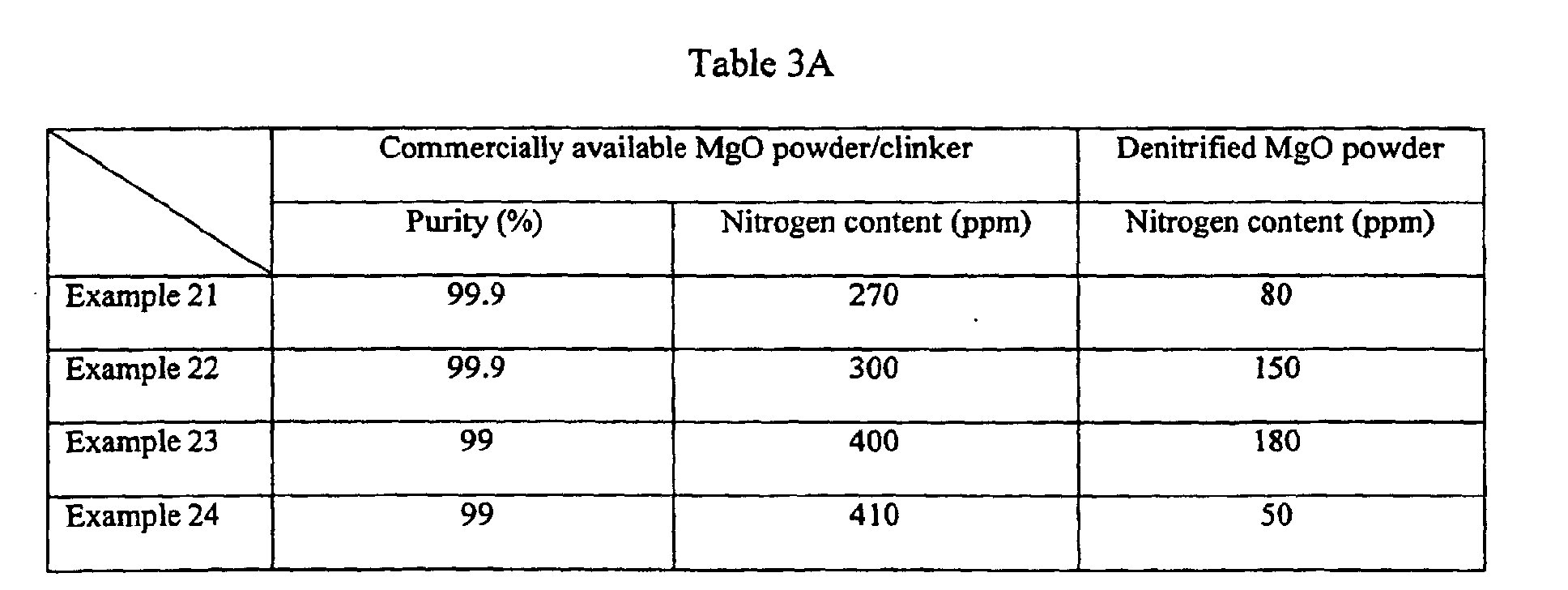
At this time, the treatment for denitrification of the raw material MgO powder
involves subjecting the MgO powder to heating under vacuum to effect denitrification,
and enables the production of a denitrified MgO powder with a reduced average nitrogen
N content.
Here, the average nitrogen N content refers to the average value for the nitrogen
N content within an entire pellet, and the respective nitrogen N contents within the
granular portion and the grain boundary portion are different.
When a polycrystalline MgO vapor deposition material is produced using this
process, a MgO vapor deposition material comprising polycrystalline pellets of sintered
MgO with a MgO purity of at least 99.0%, a relative density of at least 90.0%, and a
nitrogen N content of 0.01 to 200 ppm can be obtained.
Furthermore, the present invention may utilize a MgO powder with a purity of at
least 99.0%, a relative density of at least 90.0%, a phosphorus P content of 0.01 to 30
ppm, and an average grain diameter of 0.1 to 5 µm as the raw material, and may
comprise a step for preparing a slurry with a concentration of 45 to 75% by weight by
mixing the raw material powder, a binder and an organic solvent, a step for spray drying
the slurry to generate a granulated powder with an average grain diameter of 50 to 300
µm, a step for placing the granulated powder in a predetermined mold and molding the
powder at a predetermined pressure, and a step for sintering the molded product at a
predetermined temperature. The step for generating a granulated powder may also use a
typical rolling granulation method.
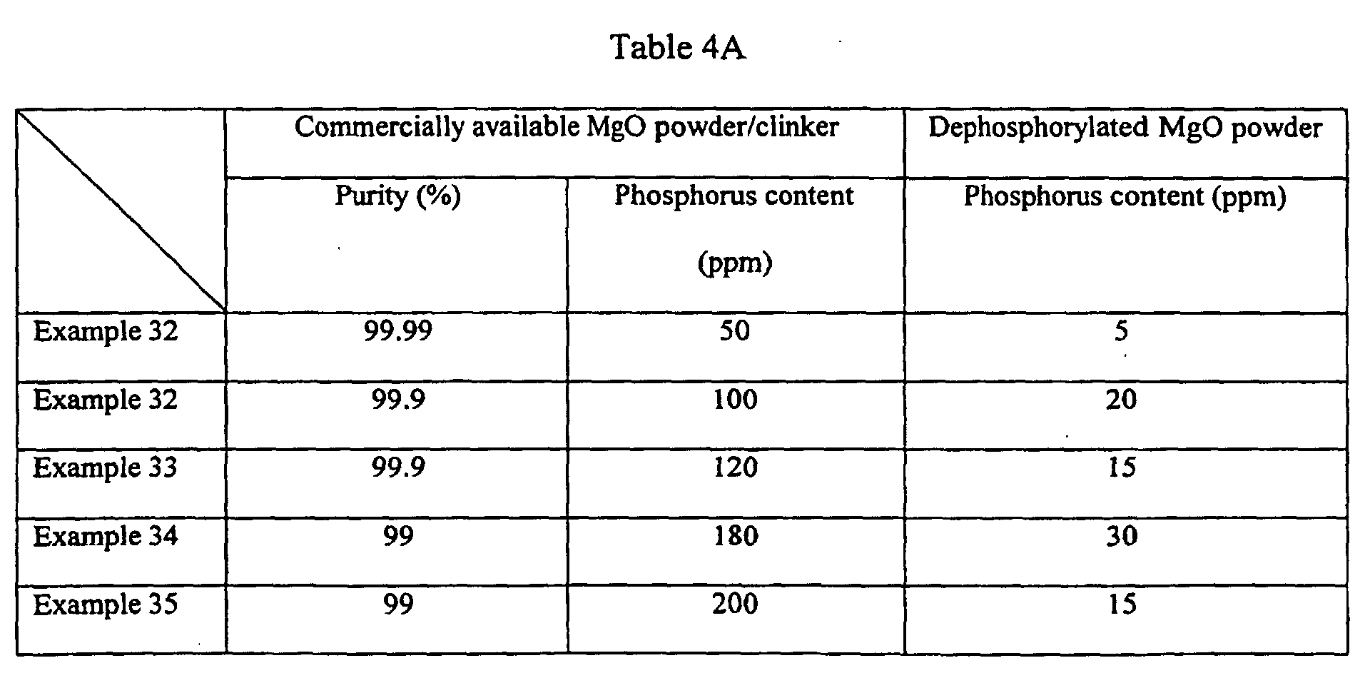
At this time, the treatment for dephosphorylation of the raw material MgO
powder involves subjecting the MgO powder to heating under vacuum to effect
dephosphorylation, and enables the production of a dephosphorylated MgO powder with
a reduced average phosphorus P content.
Here, the average phosphorus P content refers to the average value for the
phosphorus P content within an entire pellet, and the respective phosphorus P contents
within the granular portion and the grain boundary portion are different.
When a polycrystalline MgO vapor deposition material is produced using this
process, a MgO vapor deposition material comprising polycrystalline pellets of sintered
MgO with a MgO purity of at least 99.0%, a relative density of at least 90.0%, and a
phosphorus P content of 0.01 to 30 ppm can be obtained.
In addition, the granulated powder is preferably subjected to either uniaxial
pressure molding at a pressure of 750 to 2000 kg/cm2, or CIP molding at a pressure of
1000 to 3000 kg/cm2. Furthermore, the molded product is preferably first subjected to
primary sintering at a temperature of 1250 to 1350°C, and the temperature then raised
and a secondary sintering performed at a temperature of 1500 to 1700°C.
BRIEF DESCRIPTION OF THE DRAWINGS
FIG. 1 is a graph of electron beam current versus the number of splash particles,
and represents the results of splash tests for examples of the MgO vapor deposition
material according to the present invention and the production process therefor.
FIG. 2 shows the results of splash tests for examples of the MgO vapor deposition
material according to the present invention and the production process therefor, and
represents images of splash particles from a single crystal material and a polycrystalline
material.
FIG. 3 shows the results of gasification component distribution evaluations for
examples of the MgO vapor deposition material according to the present invention and
the production process therefor, and represents a TEM photograph of a sample cross
section, and the measurement positions therein.
BEST MODE FOR CARRYING OUT THE INVENTION
As follows is a detailed description of a first embodiment of a MgO vapor
deposition material according to the present invention and a production process therefor.
A MgO vapor deposition material of this embodiment comprises sintered pellets
of polycrystalline MgO with an average sulfur S content of 0.01 to 50 ppm, an average
chlorine Cl content of 0.01 to 50 ppm, an average nitrogen N content of 0.01 to 200 ppm
and an average phosphorus P content of 0.01 to 30 ppm, as well as a MgO purity of at
least 99.0%, and preferably at least 99.5%, and even more preferably at least 99.9%, and
a relative density of at least 90%, and preferably at least 97%, and even more preferably
at least 98%. Furthermore the average crystal grain diameter of the sintered pellets is
from 1 to 500 µm, and the crystal grains of the sintered polycrystalline pellets contain
rounded air pockets with an average internal diameter of no more than 10 µm.
If the sulfur S content is set to a value of less than 0.01 ppm, then the strength of
the vapor deposition material is inadequate, whereas if the sulfur S content is set to a
value greater than 50 ppm, then during film formation by either electron beam deposition
or ion plating, not only does the level of vapor deposition material splash occurrence
increase, which causes a reduction in the degree of efficiency with which the quantity of
vapor deposition material can be used in the film formation process, resulting in an
increase in material costs, but control of the crystal orientation and microstructure of the
product film also becomes difficult, and compact deposition of the MgO film component
onto the substrate is inhibited, resulting in an undesirable decrease in the film density.
If the chlorine Cl content is set to a value less than 0.01 ppm, then the strength of
the vapor deposition material is inadequate, whereas if the chlorine Cl content is set to a
value greater than 50 ppm, then during film formation by either electron beam deposition
or ion plating, not only does the level of vapor deposition material splash occurrence
increase, which causes a reduction in the degree of efficiency with which the quantity of
vapor deposition material can be used in the film formation process, resulting in an
increase in material costs, but control of the crystal orientation and microstructure of the
product film also becomes difficult, and compact deposition of the MgO film component
onto the substrate is inhibited, resulting in an undesirable decrease in the film density.
If the nitrogen N content is set to a value less than 0.01 ppm, then the strength of
the vapor deposition material is inadequate, whereas if the nitrogen N content is set to a
value greater than 200 ppm, then during film formation by either electron beam
deposition or ion plating, not only does the level of vapor deposition material splash
occurrence increase, which causes a reduction in the degree of efficiency with which the
quantity of vapor deposition material can be used in the film formation process, resulting
in an increase in material costs, but control of the crystal orientation and microstructure
of the product film also becomes difficult, and compact deposition of the MgO film
component onto the substrate is inhibited, resulting in an undesirable decrease in the film
density.
If the phosphorus P content is set to a value less than 0.01 ppm, then the strength
of the vapor deposition material is inadequate, whereas if the phosphorus P content is set
to a value greater than 30 ppm, then during film formation by either electron beam
deposition or ion plating, not only does the level of vapor deposition material splash
occurrence increase, which causes a reduction in the degree of efficiency with which the
quantity of vapor deposition material can be used in the film formation process, resulting
in an increase in material costs, but control of the crystal orientation and microstructure
of the product film also becomes difficult, and compact deposition of the MgO film
component onto the substrate is inhibited, resulting in an undesirable decrease in the film
density.
Furthermore, the reason that the average crystal grain diameter of the
polycrystalline pellets of sintered material is set to a value within a range from 1 to 500
µm is that grain diameters within this range enable better control of the MgO structure.
Furthermore, the reason that the average internal diameter of the air pockets inside the
crystal grains of the sintered pellets is set to a value of no more than 10 µm is that if this
value exceeds 10 µm, control of the MgO structure becomes difficult.
The polycrystalline pellets of sintered material comprise a granular portion
(crystal grain portion) with low concentrations of sulfur S, chlorine Cl, nitrogen N and
phosphorus P gasification components, and a grain boundary portion, which is formed
around the periphery of the granular portion (crystal grain portion) and has higher
concentrations of sulfur S, chlorine Cl, nitrogen N and phosphorus P gasification
components than the granular portion.
Specifically, the sulfur S content within the granular portion is preferably within a
range from 0.000001 to 0.005 atom%, and the sulfur S content within the grain boundary
portion is preferably within a range from 0.01 to 0.1 atom%.
Furthermore, the chlorine Cl content within the granular portion is preferably
within a range from 0.000001 to 0.003 atom%, and the chlorine Cl content within the
grain boundary portion is preferably within a range from 0.005 to 0.1 atom%.
Furthermore, the nitrogen N content within the granular portion is preferably
within a range from 0.000001 to 0.03 atom%, and the nitrogen N content within the grain
boundary portion is preferably within a range from 0.01 to 0.2 atom%.
Furthermore, the phosphorus P content within the granular portion is preferably
within a range from 0.000001 to 0.003 atom%, and the phosphorus P content within the
grain boundary portion is preferably within a range from 0.001 to 0.05 atom%.
If the sulfur S content within the granular portion is not set within the above
range from 0.000001 to 0.005 atom%, then the average sulfur S content increases, splash
occurrence becomes much more severe, and the desulfurization treatment of the raw
material becomes significantly longer, meaning large potential increases in production
costs.
Furthermore, if the sulfur S content within the grain boundary portion is not set
within the range from 0.01 to 0.1 atom%, then the splash reduction effect is
unsatisfactory.
If the chlorine Cl content within the granular portion is not set within the above
range from 0.000001 to 0.003 atom%, then the average chlorine Cl content increases,
splash occurrence becomes much more severe, and the dechlorination treatment of the
raw material becomes significantly longer, meaning large potential increases in
production costs.
Furthermore, if the chlorine Cl content within the grain boundary portion is not
set within the range from 0.005 to 0.1 atom%, then the splash reduction effect is
unsatisfactory.
If the nitrogen N content within the granular portion is not set within the above
range from 0.000001 to 0.03 atom%, then the average nitrogen N content increases,
splash occurrence becomes much more severe, and the denitrification treatment of the
raw material becomes significantly longer, meaning large potential increases in
production costs.
Furthermore, if the nitrogen N content within the grain boundary portion is not set
within the range from 0.01 to 0.2 atom%, then the splash reduction effect is
unsatisfactory.
If the phosphorus P content within the granular portion is not set within the above
range from 0.000001 to 0.003 atom%, then the average phosphorus P content increases,
splash occurrence becomes much more severe, and the dephosphorylation treatment of
the raw material becomes significantly longer, meaning large potential increases in
production costs.
Furthermore, if the phosphorus P content within the grain boundary portion is not
set within the range from 0.001 to 0.05 atom%, then the splash reduction effect is
unsatisfactory.
Furthermore, as described above, the ratio between the respective sulfur S
contents within the granular portion and the grain boundary portion is preferably set to a
value greater than 5.
If the above ratio between the respective sulfur S contents within the two portions
is less than 5, then the quantity of the sulfur S gasification component within the granular
portion becomes overly large, and the difference between the respective sulfur S contents
within the granular portion and the grain boundary portion decreases, causing an
undesirable reduction in the merit gained by ensuring an uneven distribution of the
gasification component, namely a reduction in the merit gained by generating paths in the
grain boundary portion through which the gasification component can escape during
heating, thus reducing splash occurrence. Furthermore, the total sulfur S content within
the pellets also increases, which is undesirable as it makes reductions in splash
occurrence difficult to achieve.
Furthermore, in those cases in which the above ratio between the respective sulfur
S contents is smaller than the aforementioned value, and the average sulfur S content is
not restricted, there is a possibility that the escape of the gasification component from the
pellets, which is thought to occur along the grain boundary portions, will be inhibited,
thus causing the generation of micro cracks as the gasification component undergoes
volumetric expansion, and causing a potential undesirable increase in the splash
occurrence.
Furthermore, as described above, the ratio between the respective chlorine Cl
contents within the granular portion and the grain boundary portion is preferably set to a
value greater than 5.
If the above ratio between the respective chlorine Cl contents within the two
portions is less than 5, then the quantity of the chlorine Cl gasification component within
the granular portion becomes overly large, and the difference between the respective
chlorine Cl contents within the granular portion and the grain boundary portion decreases,
causing an undesirable reduction in the merit gained by ensuring an uneven distribution
of the gasification component, namely a reduction in the merit gained by generating
paths in the grain boundary portion through which the gasification component can escape
during heating, thus reducing splash occurrence. Furthermore, the total chlorine Cl
content within the pellets also increases, which is undesirable as it makes reductions in
splash occurrence difficult to achieve.
Furthermore, in those cases in which the above ratio between the respective
chlorine Cl contents is smaller than the aforementioned value, and the average chlorine
Cl content is not restricted, there is a possibility that the escape of the gasification
component from the pellets, which is thought to occur along the grain boundary portions,
will be inhibited, thus causing the generation of micro cracks as the gasification
component undergoes volumetric expansion, and causing a potential undesirable increase
in the splash occurrence.
Furthermore, as described above, the ratio between the respective nitrogen N
contents within the granular portion and the grain boundary portion is preferably set to a
value greater than 5.
If the above ratio between the respective nitrogen N contents within the two
portions is less than 5, then the quantity of the nitrogen N gasification component within
the granular portion becomes overly large, and the difference between the respective
nitrogen N contents within the granular portion and the grain boundary portion decreases,
causing an undesirable reduction in the merit gained by ensuring an uneven distribution
of the gasification component, namely a reduction in the merit gained by generating
paths in the grain boundary portion through which the gasification component can escape
during heating, thus reducing splash occurrence. Furthermore, the total nitrogen N
content within the pellets also increases, which is undesirable as it makes reductions in
splash occurrence difficult to achieve.
Furthermore, in those cases in which the above ratio between the respective
nitrogen N contents is smaller than the aforementioned value, and the average nitrogen N
content is not restricted, there is a possibility that the escape of the gasification
component from the pellets, which is thought to occur along the grain boundary portions,
will be inhibited, thus causing the generation of micro cracks as the gasification
component undergoes volumetric expansion, and causing a potential undesirable increase
in the splash occurrence.
Furthermore, as described above, the ratio between the respective phosphorus P
contents within the granular portion and the grain boundary portion is preferably set to a
value greater than 5.
If the above ratio between the respective phosphorus P contents within the two
portions is less than 5, then the quantity of the phosphorus P gasification component
within the granular portion becomes overly large, and the difference between the
respective phosphorus P contents within the granular portion and the grain boundary
portion decreases, causing an undesirable reduction in the merit gained by ensuring an
uneven distribution of the gasification component, namely a reduction in the merit gained
by generating paths in the grain boundary portion through which the gasification
component can escape during heating, thus reducing splash occurrence. Furthermore, the
total phosphorus P content within the pellets also increases, which is undesirable as it
makes reductions in splash occurrence difficult to achieve.
Furthermore, in those cases in which the above ratio between the respective
phosphorus P contents is smaller than the aforementioned value, and the average
phosphorus P content is not restricted, there is a possibility that the escape of the
gasification component from the pellets, which is thought to occur along the grain
boundary portions, will be inhibited, thus causing the generation of micro cracks as the
gasification component undergoes volumetric expansion, and causing a potential
undesirable increase in the splash occurrence.
The thickness of the grain boundary portion is preferably within a range from 1 to
200 nm. At this point, if the thickness of the grain boundary portion is set to a value less
than 1 nm, then a grain boundary portion with comparatively high concentrations of the
sulfur S, chlorine Cl, nitrogen N and phosphorus P gasification components cannot be
formed satisfactorily, and consequently the gasification components cannot readily
escape upon heating, resulting in an undesirable increase in splash occurrence.
Furthermore, if the thickness of the grain boundary portion is set to a value exceeding
200 nm, then the respective quantities of the sulfur S, chlorine Cl, nitrogen N and
phosphorus P gasification components become overly high, causing an undesirable
increase in splash occurrence.
The total quantity of impurities (Si, Al, Ca, Fe, Cr, V, Ni, Na, K, C and Zr) within
the sintered pellets of polycrystalline MgO is preferably no more than 10,000 ppm.
Furthermore, the individual quantities of each of the above impurities are preferably
restricted to an elemental concentration of Si of no more than 5000 ppm, an elemental
concentration of Al of no more than 300 ppm, an elemental concentration of Ca of no
more than 2000 ppm, an elemental concentration of Fe of no more than 400 ppm,
elemental concentrations of each of Cr, V and Ni of no more than 50 ppm, elemental
concentrations of each of Na and K of no more than 30 ppm, an elemental concentration
of C of no more than 300 ppm, and an elemental concentration of Zr of no more than 150
ppm. If the elemental concentrations of the above impurities exceed the respective
values listed above, then when a glass substrate with a film of the MgO vapor deposition
material formed thereon by electron beam deposition is integrated into a panel, variations
develop in the film quality, causing electrical problems such as an increase or instability
in the drive voltage.
As follows is a description of a production process for a MgO vapor deposition
material described above.
First, a degasified MgO powder with gasification components including a sulfur S
content of 0.01 to 50 ppm, a chlorine Cl content of 0.01 to 50 ppm, a nitrogen N content
of 0.01 to 200 ppm, and a phosphorus P content of 0.01 to 30 ppm is prepared from a
MgO powder with a purity of at least 99.0%.
Here, the treatments for desulfurization and dechlorination involve combining the
MgO powder and water to generate a Mg(OH)2 solution, separating the sulfur S
component as MgSO4 and the chlorine Cl component as MgCl2, and then sintering the
remaining solution in the atmosphere to remove the water component, thus forming a
desulfurized and dechlorinated MgO powder with a low sulfur S content and a low
chlorine Cl content.
At the same time, the treatments for denitrification and dephosphorylation
involve subjecting the desulfurized and dechlorinated MgO powder to heating under
vacuum to effect denitrification and dephosphorylation, thus forming a degasified MgO
powder with a low nitrogen N content and low phosphorus P content..
Specifically, the denitrification and dephosphorylation heat treatment involves
heating at 330 to 500°C for a period of 0.1 to 2 hours.
This degasified MgO powder with gasification components including a sulfur S
content of 0.01 to 50 ppm, a chlorine Cl content of 0.01 to 50 ppm, a nitrogen N content
of 0.01 to 200 ppm, and a phosphorus P content of 0.01 to 30 ppm is combined with a
binder and an organic solvent to prepare a slurry with a concentration of 45 to 75% by
weight. The reason for restricting the concentration of the slurry to a value within the
range from 45 to 75% by weight is because if the concentration exceeds 75% by weight,
then because the slurry is a non-aqueous system stable granulation becomes difficult,
whereas if the concentration is less than 45% by weight, a compact MgO sintered
material with a uniform structure cannot be obtained. In other words, by restricting the
slurry concentration to a value within the above range, the slurry viscosity falls within a
range from 200 to 1000 cps, granulation of the powder using a spray dryer can conducted
in a stable manner, and the density of the molded product can be increased, enabling the
production of a compact sintered material.
Furthermore, the average grain diameter of the degasified MgO powder is
preferably within a range from 0.1 to 5 µm. The reason for restricting the average grain
diameter of the MgO powder to 0.1 to 5 µm is because at values less than 0.1 µm the
powder becomes overly fine and agglomerates, causing a significant deterioration in the
handling of the powder and making preparation of a high concentration slurry with a
concentration of at least 45% by weight difficult, whereas if the average grain diameter
exceeds 5 µm, then control of the microstructure becomes difficult, and producing
compact sintered pellets becomes impossible. Furthermore, by restricting the average
grain diameter of the MgO powder to a value within the above range, the desired sintered
pellets can be obtained without the use of a sintering assistant. The binder is preferably
polyethylene glycol or polyvinyl butyral or the like, and the organic solvent is preferably
ethanol or propanol or the like. The binder is preferably added in a concentration of 0.2
to 2.5% by weight.
Wet mixing of the MgO powder, the binder and the organic solvent, and
particularly wet mixing of the MgO powder and the organic solvent which functions as
the dispersion medium is conducted using a wet ball mill or a stirring mill. In the case of
a wet ball mill, if ZrO2 balls are used, then a plurality of ZrO2 balls with a diameter of 5
to 10 mm are used, and wet mixing is conducted for a period of 8 to 24 hours, and
preferably from 20 to 24 hours. The reason for restricting the diameter of the ZrO2 balls
to 5 to 10 mm is because with balls smaller than 5 mm the mixing action is unsatisfactory,
whereas if the ball size exceeds 10 mm, there is an increase in the quantity of impurities.
Furthermore, the reason for employing a long mixing time of up to 24 hours is that
impurity levels do not become a problem even if mixing is continued for a long period.
If resin balls containing an iron core are used in the wet ball mill, then balls of diameter
10 to 15 mm are preferred.
In the case of a stirring mill, wet mixing is conducted for 0.5 to 1 hour using ZrO2
balls of diameter 1 to 3 mm. The reason for restricting the diameter of the ZrO2 balls to 1
to 3 mm is because with balls smaller than 1 mm the mixing action is unsatisfactory,
whereas if the ball size exceeds 3 mm, there is an increase in the quantity of impurities.
Furthermore, the reasons for employing a maximum mixing time of 1 hour are firstly,
because if mixing is continued beyond 1 hour, then crushing of the raw materials occurs
in addition to mixing, which can cause increases in the level of impurities, and secondly
the fact that adequate mixing can be achieved within 1 hour.
Furthermore, mixing/granulation of the powder and the binder liquid can also be
conducted using a typical rolling granulation method. This offers an advantage in that
the process can be simplified, as the operation of separating the balls following the
mixing process is unnecessary.
Subsequently, the slurry is spray dried to generate a granulated powder with an
average grain diameter of 50 to 300 µm, and preferably from 50 to 200 µm, and this
granulated powder is then placed in a desired mold, and molded under a predetermined
pressure. The reason for restricting the average grain diameter to 50 to 300 µm is
because at values less than 50 µm the moldability is poor, whereas if the diameter
exceeds 300 µm then both the molded product density and the strength tend to be poor.
The spray drying described above is preferably conducted using a spray dryer, and the
predetermined mold uses either a uniaxial press apparatus or a CIP (Cold Isostatic Press)
molding apparatus. In the case of a uniaxial press apparatus, the granulated powder is
subjected to uniaxial pressure molding at a pressure of 750 to 2000 kg/cm2, and
preferably from 1000 to 1500 kg/cm2, whereas in the case of a CIP molding apparatus,
the granulated powder is subjected to CIP molding at a pressure of 1000 to 3000 kg/cm2,
and preferably from 1500 to 2000 kg/cm2. The reasons for restricting the pressure to
values within the above ranges are to enable an increase in the density of the molded
product, prevent deformation following sintering, and remove the necessity for posttreatments.
The molded product is then sintered. Prior to sintering, the molded product is
preferably subjected to a degreasing treatment at a temperature of 350 to 620°C. This
degreasing treatment is conducted in order to prevent irregular coloring of the molded
product following sintering, and should preferably be conducted thoroughly over a period
of time. The sintering preferably consists of a two-stage sintering process comprising
primary sintering at a temperature of 1250 to 1350°C for a period of 1 to 5 hours, and
subsequent secondary sintering at a raised temperature of 1500 to 1700°C for a period of
1 to 10 hours.
When the temperature of the molded product is raised in order to conduct the
primary sintering, sintering begins at 1200°C and proceeds significantly at 1350°C. By
conducting the primary sintering at this temperature, sintering irregularities (structural
differences) do not occur between the grain surface and the grain interior even for large
grain diameters, and by conducting the secondary sintering at a temperature of 1500 to
1700°C, sintered pellets with a relative density close to 100% can be achieved. Very
small quantities of air pockets still exist in these sintered pellets, but these air pockets do
not exist at the crystal grain boundaries where they could effect the characteristics of the
MgO sintered product, but rather exist inside the crystal grains where they have almost
no effect on the characteristics of the MgO sintered product. As a result, if these MgO
sintered pellets with a sulfur S content according to the present invention, a chlorine Cl
content according to the present invention, a nitrogen N content according to the present
invention and a phosphorus P content according to the present invention are used for film
formation within a plasma display panel, then splash occurrence is minimal, and a MgO
film with favorable film characteristics can be obtained.
In those cases where a large molded product undergoes sintering, then by
lowering the rate of temperature increase during the secondary sintering to 20 to
30°C/hour, an even more compact product can be obtained. Furthermore, in the case of
sintering at normal pressure, a satisfactory increase in compactness cannot be achieved if
the sintering temperature is less than 1500°C, whereas at sintering temperatures greater
than 1500°C, a high density sintered product can be obtained, and consequently special
sintering methods such as HIP (Hot Isostatic Press) methods or hot press methods need
not be used.
In a MgO vapor deposition material according to the present embodiment and a
production process therefor, by employing polycrystalline pellets with a MgO purity of at
least 99.0%, a relative density of at least 90.0%, and an average sulfur S content of 0.01
to 50 ppm, when a MgO protective film for an AC type PDP or the like is formed using
this MgO vapor deposition material, by either an electron beam deposition method or an
ion plating method, the level of splash occurrence can be reduced and the protective film
characteristics can be improved relative to the case of single crystal pellets.
In a MgO vapor deposition material according to the present embodiment and a
production process therefor, by employing polycrystalline pellets with a MgO purity of at
least 99.0%, a relative density of at least 90.0%, and an average chlorine Cl content of
0.01 to 50 ppm, when a MgO protective film for an AC type PDP or the like is formed
using this MgO vapor deposition material, by either an electron beam deposition method
or an ion plating method, the level of splash occurrence can be reduced and the protective
film characteristics can be improved relative to the case of single crystal pellets.
In a MgO vapor deposition material according to the present embodiment and a
production process therefor, by employing polycrystalline pellets with a MgO purity of at
least 99.0%, a relative density of at least 90.0%, and an average nitrogen N content of
0.01 to 200 ppm, when a MgO protective film for an AC type PDP or the like is formed
using this MgO vapor deposition material, by either an electron beam deposition method
or an ion plating method, the level of splash occurrence can be reduced and the protective
film characteristics can be improved relative to the case of single crystal pellets.
In a MgO vapor deposition material according to the present embodiment and a
production process therefor, by employing polycrystalline pellets with a MgO purity of at
least 99.0%, a relative density of at least 90.0%, and an average phosphorus P content of
0.01 to 30 ppm, when a MgO protective film for an AC type PDP or the like is formed
using this MgO vapor deposition material, by either an electron beam deposition method
or an ion plating method, the level of splash occurrence can be reduced and the protective
film characteristics can be improved relative to the case of single crystal pellets.
It is thought that these findings are due to the fact that by using the settings
described above, the gasification component can be reduced, thus reducing the
occurrence of splash.
Accordingly, during film formation by either electron beam deposition or ion
plating or the like, any increases in the level of splash occurrence of the vapor deposition
material can be prevented, and as a result, decreases in the degree of efficiency with
which the quantity of vapor deposition material can be used in the film formation process
can be prevented, enabling a reduction in the material costs. Moreover any increases in
the difficulty associated with controlling the crystal orientation and microstructure of the
product film can also be prevented, and the MgO film can be deposited with good
compactness onto the substrate, meaning any reduction in the film density can be
prevented.
In addition, whereas splash particles from single crystal MgO are scale-shaped,
and are thought to be generated by cleavage occurring at crystal planes, in the case of
polycrystalline MgO such as the MgO vapor deposition material of the present
embodiment, the splash particles are thought to be generated by rupture at crystal grain
boundaries, and it is thought that because the shape of these splash particles is irregular,
splash occurrence can be reduced.
In addition, because polycrystals display a higher brittleness than single crystals,
even if micro cracks are generated within the material, these do not immediately result in
splash. In other words, it is thought that compared with single crystal MgO,
polycrystalline MgO pellets are able to offer a reduction in the splash occurrence by
providing a reduction in the frequency with which the pellets themselves undergo
splitting.
Furthermore in the present embodiment, because the polycrystalline material
comprises a granular portion (a crystal grain portion) with a low sulfur S content, and a
grain boundary portion with a higher sulfur S content than the granular portion, the level
of splash occurrence can be reduced and the protective film characteristics can be
improved.
Based on the various analysis results, it is thought that the above finding is due to
the fact that the sulfur S gasification component in single crystal pellets is dispersed
essentially uniformly throughout the pellets, whereas in polycrystalline pellets, the sulfur
S gasification component is concentrated within the granular portion surface (the grain
boundary section) and the pellet surface.
Furthermore in the present embodiment, because the polycrystalline material
comprises a granular portion (a crystal grain portion) with a low chlorine Cl content, and
a grain boundary portion with a higher chlorine Cl content than the granular portion, the
level of splash occurrence can be reduced and the protective film characteristics can be
improved.
Based on the various analysis results, it is thought that the above finding is due to
the fact that the chlorine Cl gasification component in single crystal pellets is dispersed
essentially uniformly throughout the pellets, whereas in polycrystalline pellets, the
chlorine Cl gasification component is concentrated within the granular portion surface
(the grain boundary section) and the pellet surface.
Furthermore in the present embodiment, because the polycrystalline material
comprises a granular portion (a crystal grain portion) with a low nitrogen N content, and
a grain boundary portion with a higher nitrogen N content than the granular portion, the
level of splash occurrence can be reduced and the protective film characteristics can be
improved.
Based on the various analysis results, it is thought that the above finding is due to
the fact that the nitrogen N gasification component in single crystal pellets is dispersed
essentially uniformly throughout the pellets, whereas in polycrystalline pellets, the
nitrogen N gasification component is concentrated within the granular portion surface
(the grain boundary section) and the pellet surface.
Furthermore in the present embodiment, because the polycrystalline material
comprises a granular portion (a crystal grain portion) with a low phosphorus P content,
and a grain boundary portion with a higher phosphorus P content than the granular
portion, the level of splash occurrence can be reduced and the protective film
characteristics can be improved.
Based on the various analysis results, it is thought that the above finding is due to
the fact that the phosphorus P gasification component in single crystal pellets is dispersed
essentially uniformly throughout the pellets, whereas in polycrystalline pellets, the
phosphorus P gasification component is concentrated within the granular portion surface
(the grain boundary section) and the pellet surface.
In other words, it is thought that by adopting an uneven distribution of the sulfur
S, chlorine Cl, nitrogen N, and phosphorus P gasification components, which gasify and
cause volumetric expansion when heated, then even when these gasification components
undergo volumetric expansion upon heating during electron beam vapor deposition or the
like, because the micro cracks generated by this volumetric expansion are formed along
the grain boundaries, the phenomenon wherein this micro cracking acts as a trigger for
causing splash occurrence can be suppressed.
In addition, because polycrystals display a higher brittleness than single crystals,
even if micro cracks are generated within the material, these do not immediately result in
splash. Furthermore, it is surmised that because the micro cracking generates a path
through which the gasification component can escape, this further reduces the likelihood
of splash occurrence.
It is thought that this is why the quantity of splash is lower in polycrystals than in
single crystals.
In the present embodiment, by setting the ratio between the respective sulfur S
contents within the granular portion and the grain boundary portion in the manner
described above, the ratio between the sulfur S content within the granular portion and
that within the grain boundary portion can be set, and not only can the brittleness of the
material be reduced, but the quantity of the sulfur S gasification component, which acts
as a trigger for splashing, can also be reduced, enabling a more effective suppression of
splash occurrence.
In the present embodiment, by setting the ratio between the respective chlorine Cl
contents within the granular portion and the grain boundary portion in the manner
described above, the ratio between the chlorine Cl content within the granular portion
and that within the grain boundary portion can be set, and not only can the brittleness of
the material be reduced, but the quantity of the chlorine Cl gasification component,
which acts as a trigger for splashing, can also be reduced, enabling a more effective
suppression of splash occurrence.
In the present embodiment, by setting the ratio between the respective nitrogen N
contents within the granular portion and the grain boundary portion in the manner
described above, the ratio between the nitrogen N content within the granular portion and
that within the grain boundary portion can be set, and not only can the brittleness of the
material be reduced, but the quantity of the nitrogen N gasification component, which
acts as a trigger for splashing, can also be reduced, enabling a more effective suppression
of splash occurrence.
In the present embodiment, by setting the ratio between the respective phosphorus
P contents within the granular portion and the grain boundary portion in the manner
described above, the ratio between the phosphorus P content within the granular portion
and that within the grain boundary portion can be set, and not only can the brittleness of
the material be reduced, but the quantity of the phosphorus P gasification component,
which acts as a trigger for splashing, can also be reduced, enabling a more effective
suppression of splash occurrence.
In addition, by setting the thickness of the grain boundary portion to a value
within a range from 1 to 200 nm, when the sulfur S, chlorine CI, and nitrogen N, and
phosphorus P gasification components undergo volumetric expansion upon heating, paths
can be formed which allow these gasification components to readily escape from the
pellets, enabling a further reduction in the likelihood of splash occurrence.
At this point, if the thickness of the grain boundary portion is set to a value less
than 1 nm, then a grain boundary portion with comparatively high concentrations of the
sulfur S, chlorine Cl, and nitrogen N, and phosphorus P gasification components cannot
be formed satisfactorily, and consequently the gasification components cannot readily
escape upon heating, resulting in an undesirable increase in splash occurrence.
Furthermore, if the thickness of the grain boundary portion is set to a value exceeding
200 nm, then the respective quantities of the sulfur S, chlorine Cl, and nitrogen N
gasification components become overly high, causing an undesirable increase in splash
occurrence.
As follows is a detailed description of a second embodiment of a MgO vapor
deposition material according to the present invention and a production process therefor.
In this embodiment, a degasified MgO powder similar to that of the first
embodiment, with an average sulfur S content of 0.01 to 50 ppm, an average chlorine Cl
content of 0.01 to 50 ppm, an average nitrogen N content of 0.01 to 200 ppm, an average
phosphorus P content of 0.01 to 30 ppm, and a MgO purity of at least 99.0%, is subjected
to electromelting and subsequent gradual cooling to form an ingot, and single crystal
portions are then extracted from this ingot and crushed, thus preparing sheet-like single
crystal pellets with a diameter of approximately 2 to 8 mm and a central diameter of
approximately 5 mm. As a result, if these MgO single crystal pellets, which contain the
gasification component quantities described above for this embodiment, are used to form
a film on a plasma display panel, then in a similar manner to the first embodiment, a
MgO film with minimal splash occurrence and favorable film characteristics can be
obtained.
In the embodiment described above, the sulfur S, chlorine Cl and nitrogen N
gasification components were all set as described above, but any one, or any plurality of
these gasification components may be selected and their quantities set in the manner
described above.
Furthermore, by setting all four different gasification components to the values
described above at the same time, then as described above, the total gasification
component quantity can be reduced, which enables a further decrease in the splash
occurrence.
As follows is a description of specifics of the present invention based on a series
of examples and comparative examples, although provided the gist of the invention is
retained, the present invention is not limited to the following examples.
First, samples of commercially available MgO powders or clinker were subjected
to high frequency melting, and the infrared absorption of the SO2 gas discharged upon
melting was used to determine the sulfur S content. Furthermore, atomic absorption and
ICP (Inductively Coupled Plasma emission petrochemical analysis) were used to measure
the MgO purity. In the case of clinker, the sample was crushed to form a powder.
Furthermore, the MgO purity was determined as the value obtained by subtracting from
100% the quantities of the major metal atom impurities (Al, Si, Fe, Ca, Ni, Na, K, Zr, Cr,
V, C), as determined by ICP.
The results are shown in Table 1A.
For the desulfurization treatment, each of these powders was combined with
water to generate a Mg(OH)2 solution, the sulfur S component was separated as MgSO4,
and the remaining solution was sintered in the atmosphere to remove the water
component, thus yielding a desulfurized MgO powder with a low sulfur S content.
The sulfur S gasification component within each of these desulfurized MgO
powders is also shown in Table 1A.
To a sample of a desulfurized MgO powder (with an average grain diameter of
0.3 µm) that had undergone desulfurization treatment as shown in the above Table 1A
was added 1% by weight of polyethylene glycol as a binder, and a slurry with a
concentration of 30% by weight was then prepared using methanol denatured alcohol as
the dispersant. Subsequently, the slurry was subjected to wet mixing for 24 hours in a
ball mill (using nylon coated steel balls with a diameter of 5 to 20 mm), the dispersant
was then gasified at 80°C in a vacuum dryer, and dry crushing was then used to form a
granulated powder with an average grain diameter of 200 µm. This granulated powder
was then molded into a product of outer diameter 6.7 mm and thickness 2.0 mm, using a
uniaxial press apparatus and a pressure of 1000 kg/cm2. The molded product was then
placed in an electric furnace in a normal atmosphere, and then subjected to primary
sintering for 1 hour at 1300°C, followed by secondary sintering for 3 hours at 1650°C.
The thus obtained polycrystalline pellet had an outer diameter of 5.0±0.5 mm, and a
thickness of 1.6±0.2 mm. These sintered disks were used as the examples 1 to 4.
<Example 5>
A sample of desulfurized MgO powder that had undergone desulfurization
treatment as shown in the above Table 1A was subjected to electromelting and
subsequent gradual cooling to form an ingot, single crystal portions were then extracted
from this ingot and crushed, yielding sheet-like single crystal pellets with a diameter of
approximately 2 to 8 mm and a central diameter of approximately 5 mm, and these
pellets were used as the example 5.
<Comparative Examples 1 to 4>
With the exception of using the MgO powders prior to desulfurization treatment,
polycrystalline sintered pellets were prepared in the same manner as the examples 1 to 4,
and used as the comparative examples 1 to 4.
<Comparative Example 5>
With the exception of using the MgO powder prior to desulfurization treatment,
sheet-like single crystal pellets were prepared in the same manner as the example 5, and
used as the comparative example 5.
<Comparative Tests and Evaluations>
(a) Measurement of Relative Density and Sulfur S Content
The relative densities of the pellets obtained in the examples 1 to 5 and the
comparative examples 1 to 5 were measured in toluene using the Archimedes method.
Furthermore, the sulfur S content of each of the MgO pellets was measured in the same
manner as that used for the MgO powders.
The results are shown in Table 1B.
(b) Evaluation of Splash relative to Sulfur Content
In a splash test for a MgO vapor deposition material, a vapor deposition material
produced in one of the examples 1 to 5 or one of the comparative examples 1 to 5 was
placed in the hemispherical hearth (diameter 50 mm, depth 25 mm) of an electron beam
deposition apparatus, the atmosphere was adjusted to an ultimate vacuum of 2.66 × 10⁻⁴
Pa (2.0 × 10⁻⁶ Torr) and an O2 partial pressure of 1.33 × 10⁻² Pa (1.0 × 10⁻⁴ Torr), and the
MgO vapor deposition material was heated by irradiation with an electron beam, using an
accelerating voltage of 10 kV and a beam scan area of approximately 40 mm. The
electron beam current was maintained at 90 mA for 10 minutes, and during that period
the state inside the hearth was observed directly using a digital video camera, and the
number of splash particles was counted and used for the evaluation.
The results are shown in Table 1B.
(c) Evaluation of Sputtering Resistance relative to Sulfur Content
Using a MgO vapor deposition material produced in one of the examples 1 to 5 or
one of the comparative examples 1 to 5, a thin film of MgO with a film thickness of
approximately 8000 Å(800nm) was formed on top of a silicon wafer with a pre-formed
thermal oxidation film of film thickness 1000 Å(100nm), under conditions including an
ultimate vacuum of 2.66 × 10⁻⁴ Pa (2.0 × 10⁻⁶ Torr), an O2 partial pressure of 1.33 × 10⁻²
Pa (1.0 × 10⁻⁴ Torr), a substrate temperature of 200°C, a separation distance between the
MgO vapor deposition material and the substrate of 400 mm, and a film formation speed
of 15 Å/second(1.5nm/second). This thin film of MgO was subjected to surface etching
using Ar ions (2 kV), and the sputtering resistance was evaluated on the basis of the
value Sp obtained by dividing the film thickness by the time taken to etch away the entire
film thickness. The time taken to etch away the entire film thickness was taken as the
time at which the elemental concentration curves for the Mg component of the film and
the Si component of the substrate intersect. Smaller Sp values indicate more favorable
sputtering resistance.
The results are shown in Table 1B.
| | Relative density | Residual sulfur content within Mg pellet (ppm) | Splash (number) | Sputtering resistance Sp (Å/min) |
| Example 1 | 95.41 | 1 | 1 | 9.8 |
| Example 2 | 99.53 | 5 | 1 | 10.0 |
| Example 3 | 94.11 | 10 | 2 | 10.6 |
| Example 4 | 92.02 | 20 | 3 | 10.2 |
| Example 5 | 100.00 | 15 | 5 | 10.5 |
| Comparative example 1 | 94.00 | 80 | 12 | 11.8 |
| Comparative example 2 | 97.54 | 100 | 10 | 11.1 |
| Comparative example 3 | 92.57 | 120 | 16 | 12.5 |
| Comparative example 4 | 91.89 | 180 | 15 | 12.3 |
| Comparative example 5 | 99.89 | 60 | 24 | 12.1 |
From these results it is evident that when the MgO vapor deposition materials of
the examples 1 to 5 were used, the number of splash occurrences was in single figures,
and the Sp value was less than 11.0, whereas when the MgO vapor deposition materials
of the comparative examples 1 to 5 were used, the number of splash occurrences was in
double figures, and the Sp value was greater than 11.0, indicating a reduced level of
sputtering resistance.
In a similar manner to above, samples of commercially available MgO powders
or clinker were subjected to high frequency melting, the discharged chlorine gas was
trapped, the spectral transmittance of the resulting aqueous solution was measured using
a spectrophotometer, and this value was used to determine the chlorine Cl content.
Furthermore, atomic absorption and ICP were used to measure the MgO purity. In the
case of clinker, the sample was crushed to form a powder. Furthermore, the MgO purity
was determined as the value obtained by subtracting from 100% the quantities of the
major metal atom impurities (Al, Si, Fe, Ca, Ni, Na, K, Zr, Cr, V, C), as determined by
ICP.
The results are shown in Table 2A.
Each of these powders was combined with water to generate a Mg(OH)2 solution,
the chlorine Cl component was separated as MgCl2, and the remaining solution was
sintered in the atmosphere to remove the water component, thus yielding a dechlorinated
MgO powder with a low chlorine Cl content.
The chlorine Cl content within each of these dechlorinated MgO powders is also
shown in Table 2A.
To a sample of a dechlorinated MgO powder (with an average grain diameter of
0.3 µm) that had undergone dechlorination treatment as shown in the above Table 2A
was added 1% by weight of polyethylene glycol as a binder, and a slurry with a
concentration of 30% by weight was then prepared using methanol denatured alcohol as
the dispersant. Subsequently, the slurry was subjected to wet mixing for 24 hours in a
ball mill (using nylon coated steel balls with a diameter of 5 to 20 mm), the dispersant
was then gasified at 80°C in a vacuum dryer, and dry crushing was then used to form a
granulated powder with an average grain diameter of 200 µm. This granulated powder
was then molded into a product of outer diameter 6.7 mm and thickness 2.0 mm, using a
uniaxial press apparatus and a pressure of 1000 kg/cm2. The molded product was then
placed in an electric furnace in a normal atmosphere, and then subjected to primary
sintering for 1 hour at 1300°C, followed by secondary sintering for 3 hours at 1650°C.
The thus obtained polycrystalline pellet had an outer diameter of 5.0±0.5 mm, and a
thickness of 1.6±0.2 mm. These sintered disks were used as the examples 11 to 14.
<Example 15>
A sample of dechlorinated MgO powder that had undergone dechlorination
treatment as shown in the above Table 2A was subjected to electromelting and
subsequent gradual cooling to form an ingot, single crystal portions were then extracted
from this ingot and crushed, yielding sheet-like single crystal pellets with a diameter of
approximately 2 to 8 mm and a central diameter of approximately 5 mm, and these
pellets were used as the example 15.
<Comparative Examples 11 to 14>
With the exception of using the MgO powders prior to dechlorination treatment,
polycrystalline sintered pellets were prepared in the same manner as the examples 11 to
14, and used as the comparative examples 11 to 14.
<Comparative Example 15>
With the exception of using the MgO powder prior to dechlorination treatment,
sheet-like single crystal pellets were prepared in the same manner as the example 15, and
used as the comparative example 15.
<Comparative Tests and Evaluations>
(a) Measurement of Relative Density and Chlorine Cl Content
The relative densities of the pellets obtained in the examples 11 to 15 and the
comparative examples 11 to 15 were measured in toluene using the Archimedes method.
Furthermore, the chlorine Cl content of each of the MgO pellets was measured in the
same manner as that used for the MgO powders.
The results are shown in Table 2B.
(b) Evaluation of Splash relative to Chlorine Content
In a splash test for a MgO vapor deposition material, a vapor deposition material
produced in one of the examples 11 to 15 or one of the comparative examples 11 to 15
was placed in the hemispherical hearth (diameter 50 mm, depth 25 mm) of an electron
beam deposition apparatus, the atmosphere was adjusted to an ultimate vacuum of 2.66 ×
10-4 Pa (2.0 × 10⁻⁶ Torr) and an O2 partial pressure of 1.33 × 10⁻² Pa (1.0 × 10⁻⁴ Torr), and
the MgO vapor deposition material was heated by irradiation with an electron beam,
using an accelerating voltage of 10 kV and a beam scan area of approximately 40 mm.
The electron beam current was maintained at 90 mA for 10 minutes, and during that
period the state inside the hearth was observed directly using a digital video camera, and
the number of splash particles was counted and used for the evaluation.
The results are shown in Table 2B.
(c) Evaluation of Sputtering Resistance relative to Chlorine Content
Using a MgO vapor deposition material produced in one of the examples 11 to 15
or one of the comparative examples 11 to 15, a thin film of MgO with a film thickness of
approximately 8000 Å(800nm) was formed on top of a silicon wafer with a pre-formed
thermal oxidation film of film thickness 1000 Å(100nm), under conditions including an
ultimate vacuum of 2.66 × 10⁻⁴ Pa (2.0 × 10⁻⁶ Torr), an O2 partial pressure of 1.33 × 10⁻²
Pa (1.0 × 10⁻⁴ Torr), a substrate temperature of 200°C, a separation distance between the
MgO vapor deposition material and the substrate of 400 mm, and a film formation speed
of 15 Å/second(15nm/second). This thin film of MgO was subjected to surface etching
using Ar ions (2 kV), and the sputtering resistance was evaluated on the basis of the
value Sp obtained by dividing the film thickness by the time taken to etch away the entire
film thickness. The time taken to etch away the entire film thickness was taken as the
time at which the elemental concentration curves for the Mg component of the film and
the Si component of the substrate intersect. Smaller Sp values indicate more favorable
sputtering resistance.
The results are shown in Table 2B.
| | Relative density | Residual chlorine content within Mg pellet (ppm) | Splash (number) | Sputtering resistance Sp (Å/min) |
| Example 11 | 95.66 | 0.5 | 2 | 10.0 |
| Example 12 | 99.78 | 5 | 3 | 10.8 |
| Example 13 | 94.88 | 20 | 4 | 10.3 |
| Example 14 | 92.33 | 20 | 3 | 10.3 |
| Example 15 | 99.99 | 20 | 7 | 10.8 |
| Comparative example 11 | 93.88 | 60 | 20 | 11.2 |
| Comparative example 12 | 98.00 | 60 | 16 | 11.5 |
| Comparative example 13 | 92.99 | 200 | 26 | 12.2 |
| Comparative example 14 | 91.49 | 250 | 30 | 12 |
| Comparative example 15 | 99.94 | 210 | 27 | 12 |
From these results it is evident that when the MgO vapor deposition materials of
the examples 11 to 15 were used, the number of splash occurrences was in single figures,
and the Sp value was less than 11.0, whereas when the MgO vapor deposition materials
of the comparative examples 11 to 15 were used, the number of splash occurrences was
in double figures, and the Sp value was greater than 11.0, indicating a reduced level of
sputtering resistance.
In a similar manner to above, samples of commercially available MgO powders
or clinker were subjected to impulse melting, and the thermal conductivity of the
discharged NO2 gas was used to determine the nitrogen N content. Furthermore, atomic
absorption and ICP were used to measure the MgO purity. In the case of clinker, the
sample was crushed to form a powder. Furthermore, the MgO purity was determined as
the value obtained by subtracting from 100% the quantities of the major metal atom
impurities (Al, Si, Fe, Ca, Ni, Na, K, Zr, Cr, V, C), as determined by ICP.
The results are shown in Table 3A.
Each of these powders was subjected to denitrification treatment by vacuum
heating at 330 to 500°C for a period of 0.1 to 2 hours, thus yielding a denitrified MgO
powder with a low nitrogen N content.
The nitrogen N content within each of these denitrified MgO powders is also
shown in Table 3A.
To a sample of a denitrified MgO powder (with an average grain diameter of 0.3
µm) that had undergone denitrification treatment as shown in the above Table 3A was
added 1% by weight of polyethylene glycol as a binder, and a slurry with a concentration
of 30% by weight was then prepared using methanol denatured alcohol as the dispersant.
Subsequently, the slurry was subjected to wet mixing for 24 hours in a ball mill (using
nylon coated steel balls with a diameter of 5 to 20 mm), the dispersant was then gasified
at 80°C in a vacuum dryer, and dry crushing was then used to form a granulated powder
with an average grain diameter of 200 µm. This granulated powder was then molded into
a product of outer diameter 6.7 mm and thickness 2.0 mm, using a uniaxial press
apparatus and a pressure of 1000 kg/cm2. The molded product was then placed in an
electric furnace in a normal atmosphere, and then subjected to primary sintering for 1
hour at 1300°C, followed by secondary sintering for 3 hours at 1650°C. The thus
obtained polycrystalline pellet had an outer diameter of 5.0±0.5 mm, and a thickness of
1.6±0.2 mm. These sintered disks were used as the examples 21 to 23.
<Example 24>
A sample of denitrified MgO powder that had undergone denitrification treatment
as shown in the above Table 3A was subjected to electromelting and subsequent gradual
cooling to form an ingot, single crystal portions were then extracted from this ingot and
crushed, yielding sheet-like single crystal pellets with a diameter of approximately 2 to 8
mm and a central diameter of approximately 5 mm, and these pellets were used as the
example 24.
<Comparative Examples 21 to 23>
With the exception of using the MgO powders prior to denitrification treatment,
polycrystalline sintered pellets were prepared in the same manner as the examples 21 to
23, and used as the comparative examples 21 to 23.
<Comparative Example 24>
With the exception of using the MgO powder prior to denitrification treatment,
sheet-like single crystal pellets were prepared in the same manner as the example 24, and
used as the comparative example 24.
<Comparative Tests and Evaluations>
(a) Measurement of Relative Density and Nitrogen N Content
The relative densities of the pellets obtained in the examples 21 to 24 and the
comparative examples 21 to 24 were measured in toluene using the Archimedes method.
Furthermore, the nitrogen N content of each of the MgO pellets was measured in the
same manner as that used for the MgO powders.
The results are shown in Table 3B.
(b) Evaluation of Splash relative to Nitrogen Content
In a splash test for a MgO vapor deposition material, a vapor deposition material
produced in one of the examples 21 to 24 or one of the comparative examples 21 to 24
was placed in the hemispherical hearth (diameter 50 mm, depth 25 mm) of an electron
beam deposition apparatus, the atmosphere was adjusted to an ultimate vacuum of 2.66 ×
10-4 Pa (2.0 × 10⁻⁶ Torr) and an O2 partial pressure of 1.33 × 10⁻² Pa (1.0 × 10⁻⁴ Torr), and
the MgO vapor deposition material was heated by irradiation with an electron beam,
using an accelerating voltage of 10 kV and a beam scan area of approximately 40 mm.
The electron beam current was maintained at 90 mA for 10 minutes, and during that
period the state inside the hearth was observed directly using a digital video camera, and
the number of splash particles was counted and used for the evaluation.
The results are shown in Table 3B.
(c) Evaluation of Sputtering Resistance relative to Nitrogen Content
Using a MgO vapor deposition material produced in one of the examples 21 to 24
or one of the comparative examples 21 to 24, a thin film of MgO with a film thickness of
approximately 8000 Å (800nm)was formed on top of a silicon wafer with a pre-formed
thermal oxidation film of film thickness 1000 Å(100nm), under conditions including an
ultimate vacuum of 2.66 × 10⁻⁴ Pa (2.0 × 10⁻⁶ Torr), an O2 partial pressure of 1.33 × 10⁻²
Pa (1.0 × 10⁻⁴ Torr), a substrate temperature of 200°C, a separation distance between the
MgO vapor deposition material and the substrate of 400 mm, and a film formation speed
of 15 Å/second(1.5nm/second). This thin film of MgO was subjected to surface etching
using Ar ions (2 kV), and the sputtering resistance was evaluated on the basis of the
value Sp obtained by dividing the film thickness by the time taken to etch away the entire
film thickness. The time taken to etch away the entire film thickness was taken as the
time at which the elemental concentration curves for the Mg component of the film and
the Si component of the substrate intersect. Smaller Sp values indicate more favorable
sputtering resistance.
The results are shown in Table 3B.
| | Relative density | Residual nitrogen content within Mg pellet (ppm) | Splash (number) | Sputtering resistance Sp (Å/min) |
| Example 21 | 99.50 | 0.5 | 3 | 10.7 |
| Example 22 | 94.84 | 20 | 2 | 10.6 |
| Example 23 | 92.22 | 100 | 3 | 10.8 |
| Example 24 | 100.00 | 40 | 6 | 10.8 |
| Comparative example 21 | 97.13 | 230 | 15 | 11.3 |
| Comparative example 22 | 92.88 | 250 | 22 | 12.0 |
| Comparative example 23 | 91.41 | 330 | 18 | 12.2 |
| Comparative example 24 | 99.80 | 300 | 26 | 12.5 |
From these results it is evident that when the MgO vapor deposition materials of
the examples 21 to 24 were used, the number of splash occurrences was in single figures,
and the Sp value was less than 11.0, whereas when the MgO vapor deposition materials
of the comparative examples 21 to 24 were used, the number of splash occurrences was
in double figures, and the Sp value was greater than 11.0, indicating a reduced level of
sputtering resistance.
In a similar manner to above, samples of commercially available MgO powders
or clinker were subjected to impulse melting, and the thermal conductivity of the
discharged PO2 gas was used to determine the phosphorus P content. Furthermore,
atomic absorption and ICP were used to measure the MgO purity. In the case of clinker,
the sample was crushed to form a powder. Furthermore, the MgO purity was determined
as the value obtained by subtracting from 100% the quantities of the major metal atom
impurities (Al, Si, Fe, Ca, Ni, Na, K, Zr, Cr, V, C), as determined by ICP.
The results are shown in Table 4A.
Each of these powders was subjected to dephosphorylation treatment by vacuum
heating at 800 to 1200°C for a period of 0.1 to 2 hours, thus yielding a dephosphorylated
MgO powder with a low phosphorus P content.
The phosphorus P content within each of these dephosphorylated MgO powders
is also shown in Table 4A.
To a sample of a dephosphorylated MgO powder (with an average grain diameter
of 0.3 µm) that had undergone dephosphorylation treatment as shown in the above Table
14A was added 1% by weight of polyethylene glycol as a binder, and a slurry with a
concentration of 30% by weight was then prepared using methanol denatured alcohol as
the dispersant. Subsequently, the slurry was subjected to wet mixing for 24 hours in a
ball mill (using nylon coated steel balls with a diameter of 5 to 20 mm), the dispersant
was then gasified at 80°C in a vacuum dryer, and dry crushing was then used to form a
granulated powder with an average grain diameter of 200 µm. This granulated powder
was then molded into a product of outer diameter 6.7 mm and thickness 2.0 mm, using a
uniaxial press apparatus and a pressure of 1000 kg/cm2. The molded product was then
placed in an electric furnace in a normal atmosphere, and then subjected to primary
sintering for 1 hour at 1300°C, followed by secondary sintering for 3 hours at 1650°C.
The thus obtained polycrystalline pellet had an outer diameter of 5.0±0.5 mm, and a
thickness of 1.6±0.2 mm. These sintered disks were used as the examples 31 to 34.
<Example 35>
A sample of dephosphorylated MgO powder that had undergone
dephosphorylation treatment as shown in the above Table 14A was subjected to
electromelting and subsequent gradual cooling to form an ingot, single crystal portions
were then extracted from this ingot and crushed, yielding sheet-like single crystal pellets
with a diameter of approximately 2 to 8 mm and a central diameter of approximately 5
mm, and these pellets were used as the example 35.
<Comparative Examples 31 to 34>
With the exception of using the MgO powders prior to dephosphorylation
treatment, polycrystalline sintered pellets were prepared in the same manner as the
examples 31 to 34, and used as the comparative examples 31 to 34.
<Comparative Example 35>
With the exception of using the MgO powder prior to dephosphorylation
treatment, sheet-like single crystal pellets were prepared in the same manner as the
example 35, and used as the comparative example 35.
<Comparative Tests and Evaluations>
(a) Measurement of Relative Density and Phosphorus P Content
The relative densities of the pellets obtained in the examples 31 to 35 and the
comparative examples 31 to 35 were measured in toluene using the Archimedes method.
Furthermore, the phosphorus P content of each of the MgO pellets was measured in the
same manner as that used for the MgO powders.
The results are shown in Table 4B.
(b) Evaluation of Splash relative to Phosphorus Content
In a splash test for a MgO vapor deposition material, a vapor deposition material
produced in one of the examples 31 to 35 or one of the comparative examples 31 to 35
was placed in the hemispherical hearth (diameter 50 mm, depth 25 mm) of an electron
beam deposition apparatus, the atmosphere was adjusted to an ultimate vacuum of 2.66 ×
10-4 Pa (2.0 × 10⁻⁶ Torr) and an O2 partial pressure of 1.33 × 10⁻² Pa (1.0 × 10⁻⁴ Torr), and
the MgO vapor deposition material was heated by irradiation with an electron beam,
using an accelerating voltage of 10 kV and a beam scan area of approximately 40 mm.
The electron beam current was maintained at 90 mA for 10 minutes, and during that
period the state inside the hearth was observed directly using a digital video camera, and
the number of splash particles was counted and used for the evaluation.
The results are shown in Table 4B.
(c) Evaluation of Sputtering Resistance relative to Phosphorus Content
Using a MgO vapor deposition material produced in one of the examples 31 to 35
or one of the comparative examples 31 to 35, a thin film of MgO with a film thickness of
approximately 8000 Å(800nm) was formed on top of a silicon wafer with a pre-formed
thermal oxidation film of film thickness 1000 Å(100nm), under conditions including an
ultimate vacuum of 2.66 × 10⁻⁴ Pa (2.0 × 10⁻⁶ Torr), an O2 partial pressure of 1.33 × 10⁻²
Pa (1.0 × 10⁻⁴ Torr), a substrate temperature of 204°C, a separation distance between the
MgO vapor deposition material and the substrate of 400 mm, and a film formation speed
of 15 Å/second(1.5nm/second). This thin film of MgO was subjected to surface etching
using Ar ions (2 kV), and the sputtering resistance was evaluated on the basis of the
value Sp obtained by dividing the film thickness by the time taken to etch away the entire
film thickness. The time taken to etch away the entire film thickness was taken as the
time at which the elemental concentration curves for the Mg component of the film and
the Si component of the substrate intersect. Smaller Sp values indicate more favorable
sputtering resistance.
The results are shown in Table 4B.
| | Relative density | Residual phosphorus content within Mg pellet (ppm) | Splash (number) | Sputtering resistance Sp (Å/min) |
| Example 31 | 95.20 | 0.5 | 1 | 10.0 |
| Example 32 | 99.01 | 17 | 1 | 9.8 |
| Example 33 | 95.01 | 8 | 2 | 10.8 |
| Example 34 | 92.77 | 20 | 2 | 10.9 |
| Example 35 | 100.00 | 10 | 7 | 10.7 |
| Comparative example 31 | 94.88 | 40 | 13 | 11.6 |
| Comparative example 32 | 97.54 | 60 | 10 | 11.6 |
| Comparative example 33 | 92.57 | 70 | 19 | 12.0 |
| Comparative example 34 | 91.89 | 120 | 11 | 12.5 |
| Comparative example 35 | 99.89 | 50 | 19 | 12.0 |
From these results it is evident that when the MgO vapor deposition materials of
the examples 31 to 35 were used, the number of splash occurrences was in single figures,
and the Sp value was less than 11.0, whereas when the MgO vapor deposition materials
of the comparative examples 31 to 35 were used, the number of splash occurrences was
in double figures, and the Sp value was greater than 11.0, indicating a reduced level of
sputtering resistance.
<Comparative Tests and Evaluations (continued)>
(d) Hardness (Material Brittleness) Comparison between Single Crystals and Polycrystals
The polycrystalline pellets formed by sintering of the example 3, and the single
crystal pellets formed by electromelting of the example 5 were subjected to Vickers
hardness (Hv) and fracture toughness (KIC) measurements.
The Vickers hardness (Hv) measurements produced results of 608±35 and
698±51 (actual measured values) for the example 3 and the example 5 respectively, with
the result for the single crystals of the example 5 being approximately 15% higher,
whereas the fracture toughness (KIC) measurements produced results of 1.91 Mpa·m1/2
and 1.26 Mpa·m1/2 (actual measured values) for the example 3 and the example 5
respectively, with the result for the single crystals of the example 5 being approximately
34% lower. It is thought that these results suggest that in the case of single crystals, once
a micro crack forms, it immediately propagates, making the occurrence of splash of
vapor deposition material fragments more likely.
(e) Splash Comparative Tests based on Crystal Type
Using the same splash evaluation described in section (b) above, splash tests were
conducted using the polycrystalline pellets of the example 3 and the single crystal pellets
of the example 5.
The splash evaluations were essentially the same as those described above,
although the electron beam current was increased sequentially from 30 to 240 mA, and
the values obtained by maintaining each current for 1 minute were recorded. The results
are shown in FIG. 1.
From the results shown in FIG. 1 it is evident that compared with the single
crystal pellets, the polycrystalline pellets of the example 3 displayed less than half the
level of splash occurrence.
Furthermore, the splash particles that were generated in the tests were also
examined. The results are shown in FIG. 2.
As can be seen in FIG. 2, the splash particles from the single crystals are scale-shaped,
and it is surmised that these are generated by cleavage occurring at crystal planes.
In contrast, in the case of polycrystals, the splash particles are of irregular shape, and it is
thought that these are generated by rupture at crystal grain boundaries. In single crystals
the gasification components are distributed uniformly through the interior of the crystals,
whereas in the case of polycrystals, the gasification components are concentrated at the
surface or grain boundary interface (as indicated by each of the analysis results), and it is
thought that volumetric expansion on heating of the gasification component in the
interior of the material acts as a trigger for splash occurrence. Because polycrystals
display a higher brittleness than single crystals, even if micro cracks are generated within
the material, these do not immediately result in splash. Furthermore, it is surmised that
because the micro cracking generates a path through which the gasification component
can escape, this further reduces the likelihood of splash occurrence. It is thought that this
is why the quantity of splash observed was lower in polycrystals than in single crystals
(see Table 1B, Table 2B, Table 3B, Table 4B and FIG. 1). As described above, the
brittleness of the material is also important, although from the results shown in Table 1B,
Table 2B, Table 3B and Table 4B it is evident that reducing the gasification components
that act as triggers for splash occurrence is even more effective in further suppressing
splash.
(f) Evaluation of Gasification Component Distribution
Using the polycrystalline pellets of the example 4, the following compositional
and structural analyses were performed for the granular portion, the grain boundary
portion, the outermost surface portion and the overall pellets.
These results are shown in Table 5, Table 6 and FIG. 3.
FIG. 3 shows a TEM photograph of a sample cross section, and in this figure,
numerals 1 to 5 show measurement points, wherein
numerals 1 to 3 are positioned at
grain boundary portions, and
numerals 4 and 5 are positioned within crystal grain
portions (granular portions). In the tables, these
points 1 to 5 are labeled as #1 to #5
respectively.
| Grain boundary (analysis area: 30 nm) |
| | #1 | #2 | #3 | average |
| Mg | 48.87 | 48.54 | 47.75 | 48.39 |
| O | 49.78 | 50.53 | 50.94 | 50.42 |
| Si | 0.60 | 0.64 | 0.72 | 0.65 |
| Fe | 0.19 | 0.04 | 0.13 | 0.12 |
| Cr | 0.00 | 0.00 | 0.01 | 0.00 |
| Ca | 0.02 | 0.00 | 0.00 | 0.01 |
| Al | 0.26 | 0.00 | 0.23 | 0.16 |
| Ni | 0.00 | 0.00 | 0.00 | 0.00 |
| Na | 0.08 | 0.00 | 0.00 | 0.03 |
| K | 0.00 | 0.03 | 0.00 | 0.01 |
| Cl | 0.01 | 0.01 | 0.00 | 0.01 |
| N | 0.14 | 0.14 | 0.13 | 0.14 |
| S | 0.04 | 0.03 | 0.03 | 0.03 |
| P | 0.04 | 0.04 | 0.04 | 0.04 |
| Units: Atom% |
| Grain interior (analysis area: 30 nm) |
| | #4 | #5 | average |
| Mg | 48.87 | 48.54 | 48.71 |
| O | 50.52 | 51.18 | 50.85 |
| Si | 0.04 | 0.20 | 0.12 |
| Fe | 0.00 | 0.00 | 0.00 |
| Cr | 0.01 | 0.02 | 0.01 |
| Ca | 0.02 | 0.03 | 0.02 |
| Al | 0.00 | 0.00 | 0.00 |
| Ni | 0.00 | 0.00 | 0.00 |
| Na | 0.49 | 0.00 | 0.25 |
| K | 0.01 | 0.00 | 0.01 |
| Cl | 0.00 | 0.00 | 0.00 |
| N | 0.02 | 0.02 | 0.02 |
| S | 0.00 | 0.00 | 0.00 |
| P | 0.00 | 0.00 | 0.00 |
| Units: Atom% |
The phosphorus P in the polycrystal outermost layer is present in a variety of
forms such as phosphates, phosphoric acid (P4O10) and metaphosphates, and it is
assumed that this is also true of the grain boundary portion.
In contrast, in the overall analysis, the phosphorus P content was 30 ppm (0.003%
by weight), meaning the approximate quantity of phosphorus P is less than 0.003 atom%,
and indicating that the vast majority of phosphorus P exists at the grain boundaries, and
that the ratio of phosphorus P in the grain boundary portion relative to the granular
portion is at least 13.
In this manner, from the results of Table 5 and Table 6 it is clear that almost no
gasification component exists in the crystal grain portion (the granular portion), and that
the gasification component is concentrated almost entirely within the grain boundary
portion.
INDUSTRIAL APPLICABILITY
According to a MgO vapor deposition material of the present invention, by
ensuring a MgO purity of at least 99.0%, a relative density of at least 90.0%, a sulfur S
content of 0.01 to 50 ppm, a chlorine Cl content of 0.01 to 50 ppm, a nitrogen N content
of 0.01 to 200 ppm, and a phosphorus P content of 0.01 to 30 ppm, when the MgO vapor
deposition material is used for forming a MgO protective film for an AC type PDP or the
like by either an electron beam deposition method or an ion plating method, the level of
splash occurrence can be reduced, and the protective film characteristics such as the
MgO film density, the film thickness distribution, the light transmittance, the sputtering
resistance, the discharge characteristics (such as the discharge voltage and the discharge
response), and the insulating characteristics can be improved.
Furthermore, in a production process for a MgO vapor deposition material
according to the present invention, by using a MgO powder with a sulfur S content of
0.01 to 50 ppm, a chlorine Cl content of 0.01 to 50 ppm, a nitrogen N content of 0.01 to
200 ppm, and a phosphorus P content of 0.01 to 30 ppm as the raw material, the type of
MgO vapor deposition material described above can be produced.