EP1481895A1 - Dispositif d'accrochage arrière de moteur d'avion - Google Patents
Dispositif d'accrochage arrière de moteur d'avion Download PDFInfo
- Publication number
- EP1481895A1 EP1481895A1 EP04291252A EP04291252A EP1481895A1 EP 1481895 A1 EP1481895 A1 EP 1481895A1 EP 04291252 A EP04291252 A EP 04291252A EP 04291252 A EP04291252 A EP 04291252A EP 1481895 A1 EP1481895 A1 EP 1481895A1
- Authority
- EP
- European Patent Office
- Prior art keywords
- engine
- links
- link
- axis
- mast
- Prior art date
- Legal status (The legal status is an assumption and is not a legal conclusion. Google has not performed a legal analysis and makes no representation as to the accuracy of the status listed.)
- Granted
Links
Images


Classifications
-
- B—PERFORMING OPERATIONS; TRANSPORTING
- B64—AIRCRAFT; AVIATION; COSMONAUTICS
- B64D—EQUIPMENT FOR FITTING IN OR TO AIRCRAFT; FLIGHT SUITS; PARACHUTES; ARRANGEMENT OR MOUNTING OF POWER PLANTS OR PROPULSION TRANSMISSIONS IN AIRCRAFT
- B64D27/00—Arrangement or mounting of power plants in aircraft; Aircraft characterised by the type or position of power plants
- B64D27/40—Arrangements for mounting power plants in aircraft
- B64D27/404—Suspension arrangements specially adapted for supporting vertical loads
-
- B—PERFORMING OPERATIONS; TRANSPORTING
- B64—AIRCRAFT; AVIATION; COSMONAUTICS
- B64D—EQUIPMENT FOR FITTING IN OR TO AIRCRAFT; FLIGHT SUITS; PARACHUTES; ARRANGEMENT OR MOUNTING OF POWER PLANTS OR PROPULSION TRANSMISSIONS IN AIRCRAFT
- B64D27/00—Arrangement or mounting of power plants in aircraft; Aircraft characterised by the type or position of power plants
- B64D27/40—Arrangements for mounting power plants in aircraft
-
- B—PERFORMING OPERATIONS; TRANSPORTING
- B64—AIRCRAFT; AVIATION; COSMONAUTICS
- B64D—EQUIPMENT FOR FITTING IN OR TO AIRCRAFT; FLIGHT SUITS; PARACHUTES; ARRANGEMENT OR MOUNTING OF POWER PLANTS OR PROPULSION TRANSMISSIONS IN AIRCRAFT
- B64D27/00—Arrangement or mounting of power plants in aircraft; Aircraft characterised by the type or position of power plants
- B64D27/40—Arrangements for mounting power plants in aircraft
- B64D27/406—Suspension arrangements specially adapted for supporting thrust loads, e.g. thrust links
Definitions
- the present invention relates to the suspension of propulsion engines to the structure of an airplane. It concerns in particular a suspension or a rear attachment device comprising means for maintaining suspension in function in case of accidental breakage of one of its rooms.
- a propulsion engine can be mounted at various points on the airplane in being attached to a mast belonging to the structure of the latter. He can be suspended under the wings, attached to the fuselage or mounted in the empennage by hooking means. These attachment means have the function of to ensure the transmission of mechanical forces between the engine and the structure of the plane.
- the charges to be considered are oriented according to the three main directions. These include the weight of engine, its thrust, and lateral aerodynamic loads. Charges to transmit also include the reversion of the torque around the axis of the engine. These means must also absorb the deformations suffered by the engine during the different phases of the flight due to in particular dimensional variations due to expansions or thermal contractions
- a suspension mode for example, in the case of a turbine engine with blower, consists in hanging the engine on a mast belonging to the structure of the aircraft wing by a suspension or attachment before and a suspension or rear attachment.
- the front suspension is fixed in particular on the outer casing of the blower and the rear suspension on the casing exhaust of the primary flow.
- the front fastener is arranged to ensure the transmission of vertical and tangential mechanical forces between the engine and the plane.
- the rear attachment is arranged to ensure the passage of efforts mechanical following these same directions, as well as the recovery of the couple engine around the axis of the turbine engine and the thrust recovery. This last is transmitted via two resumption bars of thrust on the front, at the base of the fan case on the other side of the longitudinal axis, and at the rear by means of a rear suspension of the motor.
- the present invention relates to a fastener arranged to transmit the vertical and lateral forces between the engine and the mast of the aircraft. It's about in the configuration recalled above of the rear attachment.
- Applicant's patent EP 527672 describes a fastener of this type. It includes three ears or external hooks which are made in one piece at the top of the housing exhaust of the turbojet engine. These ears allow to fix the housing exhaust at the lower ends of three suspension rods whose upper ends are mounted on a hanging structure disposed substantially in an arc in a transverse plane relative to to the motor axis.
- This attachment structure comprises a fitting to which the rods are hooked by a suspension pin longitudinal. This fitting is itself fixed under the mast by means appropriate.
- the connecting rods allow the transmission of tensile and compressive forces along their axis.
- the links are fastened at their other end to ears or clevises of a fitting lower integral with the exhaust casing.
- the solution presented in this patent relates to a means of avoiding the engine stall in the event that a mechanical failure occurs at the level of this fitting.
- the attachment devices also generally incorporate means of safety to prevent engine stall, in case of breakage, no not the hardware but a rod ,.
- means of safety to prevent engine stall, in case of breakage, no not the hardware but a rod .
- a fastening device comprising a first connecting rod and a second connecting rod between the two upper and lower brackets.
- the first connecting rod is mounted by a spherical connection on one ear of the engine, and two separate links the upper bracket, one of which is ball and the other is axial.
- the second connecting rod is linked to an engine lug by a ball joint and to the upper fitting by a single ball joint in normal operation.
- a second link is provided, but for this one the link axis is mounted on its counterpart with a game. In normal operation, this second link remains inactive.
- the device comprises a third connecting rod, between the two fittings, which remains waiting also by the presence clearance between the connecting pin and their respective housing on the fittings. In normal operation, the transmission of efforts is ensured by the first of the connecting rods because of its two points of connection with the hardware higher.
- the second connecting rod transmits the forces of tension and contraction due to its mounting with a single link.
- first and second connecting rods are in the form of boomerang and have some symmetry. They are not however interchangeable because one of the axes of the second connecting rod is mounted with play while the three axes are active in the first.
- the two main rods are almost identical shapes. At assembly the technician must respect a very precise mode of operation and proceed with great attention. The risk of error of mounting a part for another is not negligible.
- the plaintiff has set itself the goal of producing a device of engine attachment to the structure of the aircraft whose risk of error mounting are reduced.
- the invention achieves these objectives with a hooking device of a turbine engine at the mast of an aircraft comprising an upper fitting provided fastening means to the mast, on which are articulated by first linkages, three links arranged in a plane transverse to the longitudinal axis of the engine, first and second links of both sides of the motor shaft and a third link between them, the links being themselves connected to the engine by second links to joints, characterized in that the first and second links each have a third link waiting and that the fitting upper is formed of a beam rigidly attached to the mast.
- each link waiting is carried out by a hinge connection with a hinge pin mounted with play in his dwelling.
- each link waiting is a link to articulation with a longitudinal axis of articulation mounted with play in its housing, the two games being identical.
- the third link waiting connects the rod to the upper bracket.
- first and second connecting rods are identical. So thanks to the invention, there is provided a fastening device with security means with a reduced number of different parts.
- the first and second means articulated links comprise a ball joint for absorbing force components that are not oriented perpendicular to the longitudinal axis of articulation.
- FIG. 1 represents a three-quarter view of a turbojet engine 1 equipped its means of attachment to an aircraft mast which is not shown. he may include the attachment to the wing of an aircraft.
- the engine comprises a fastening device 40 in front of the motor, attached to the outer casing of the blower. It also has a attachment means 10 at the rear, attached to the exhaust casing of the flow primary. The resumption of the thrust is ensured by two bars 50 hung at the base of the blower housing and at the rear attachment.
- the present invention relates to the rear attachment which is described below in 2 to 4.
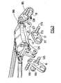
- the fastener 10 is composed of a fitting 12 upper, and three connecting rods 16, 17 and 18 connecting the fitting 12 to ears or integral screeds of the exhaust casing, not shown.
- these ears are the components of a lower fitting unique.
- the connecting rods are rectilinear.
- the upper bracket consists of a beam 120 with, here, four housing for the passage of bolts or screws with which we make the rigid fitting of the mast of the aircraft rigidly.
- the beam is of form substantially rectangular; it is arranged in a cross-machine direction with respect to the longitudinal axis of the engine.
- the beam extends on both sides of the axis of the motor, by two clevises, 126 and 128 respectively, for the connecting rods, 16 and 18 respectively.
- a third clevis 127 secured to the beam below, provides the connection with the connecting rod 17.
- the details of the links are as follows.
- the rod 16 for example is connected to a clevis of the engine by a first link 161 with an axis 162.
- the axis 162 through the ears constituting the clevis of the engine and the connecting rod 16 and is held by appropriate sockets.
- the sleeve 163 visible in Figure 4 between the axis 161 and the rod is surface outer spherical so as to form a ball joint. Forces which are exercised between the connecting rod and the clevis and which are not in the plane orthogonal to the axis 162 are thus not transmitted.
- This type of link is in well known in the field.
- the ball joint has the particularity to transmit only the forces in tension and in compression by the axis 162.
- the ball 163 has not been shown in FIG. 2.
- the rod 16 is connected to the yoke 126 by a second link 164 which, here, is advantageously also ball joint as the first. It includes a axis 165 and a socket with a spherical surface 166 on the connecting rod 16.
- the axis 165 is rotatably mounted in housings formed in the yoke 126 by through appropriate sockets.
- the connecting rod 16 is connected to the yoke 126 by a third link 167 which is pending.
- a link which in normal operation remains inactive; she does not transmits no force. It becomes active and transmits efforts in case of breakage of determined parts of the fastener.
- Such a connection is made by example, by means of an axis 168 mounted with radial clearance E1 in housings aligned on the connecting rod on the one hand and on the yoke 126 on the other hand. The game is sufficient for the axis to remain inactive in all phases of the game. flight.
- the connecting rod 18 comprises, like the connecting rod 16, a first connection 181 with a ball joint and axis 182 with a motor clevis.
- the patella has not been represented. It is connected by a second ball joint 184 and axis 185 at clevis 128. It also includes a link waiting 187 with the Clevis 128.
- This connection is preferably made as in the clevis 126, by means of an axis 188 mounted with a defined radial clearance E2 in housings aligned on the clevis and the connecting rod.
- the games E1 and E2 are identical.
- the two rods have the same shape, preferably, and are interchangeable. They are advantageously rectilinear.
- a third connecting rod 17, disposed between the first two, comprises a first connecting means 171 with a clevis secured to the motor.
- the axis 172 crosses the connecting rod and ears of the clevis in one direction longitudinal to the engine.
- a second link 173 is constituted by an axis 175 which passes through the connecting rod 17 and the yoke 127 on the upper fitting 12.
- both rods 16 and 18 have a symmetrical inclination with respect to the vertical direction passing through the axis of the engine. They are arranged in trapeze. These two rods transmit for example to the structure of the aircraft the weight of the engine and the lateral forces to which it is subjected during the flight.
- the two pending links 167 and 187 are inactive. Because of games E1 and E2 no force is transmitted by these links whatever the phase of the flight.
- the third rod has an inclination relative to the horizontal. She is disposed near the vertical plane passing through the axis of the engine, and transmits to the supporting structure the torque exerted by the casing due to the rotation of the motor.
- the connecting rod 16 for example breaks, it occurs a tilting between the two fittings around the connecting rod 18 until the radial play of the third link 187 has disappeared. This displacement is also produced in case of failure of another room located in the trajectory of the forces passing through the connecting rod 16, such as the beam of the upper fitting, an ear of the yoke 146 or a ball joint.
- connection between the two fittings then becomes rigid. This liaison ensures transmission of both vertical and / or lateral forces and also the couple due to the rotation of the motor.
Landscapes
- Engineering & Computer Science (AREA)
- Aviation & Aerospace Engineering (AREA)
- Pivots And Pivotal Connections (AREA)
- Transmission Devices (AREA)
- Shafts, Cranks, Connecting Bars, And Related Bearings (AREA)
- Supercharger (AREA)
- Clamps And Clips (AREA)
- Structures Of Non-Positive Displacement Pumps (AREA)
- Axle Suspensions And Sidecars For Cycles (AREA)
Abstract
Description
Claims (6)
- Dispositif d'accrochage d'un turbomoteur (1) au mât d'un avion comprenant une ferrure supérieure (12) pourvue de moyens de fixation au mât, sur laquelle sont articulées, par des secondes liaisons (163, 183) à articulation, trois biellettes transversalement à l'axe longitudinal du moteur, une première (16) et une deuxième (18) biellettes de part et d'autre de l'axe du moteur et une troisième biellette (17) entre elles deux, les biellettes étant elles-mêmes reliées au moteur par des premières liaisons (161, 181) à articulations, caractérisé par le fait que les première (16) et deuxième (18) biellettes comportent chacune une troisième (167, 187) liaison en attente et que la ferrure supérieure (12) est formée d'une poutre (120) fixée rigidement au mât.
- Dispositif selon la revendication 1 dont au moins l'une des deux liaisons (167,187) en attente est réalisée par une liaison à articulation avec un axe (168, 188) d'articulation monté avec jeu dans son logement.
- Dispositif selon la revendication 2 dont chaque liaison en attente (167, 187) est une liaison à articulation avec un axe d'articulation monté avec jeu dans son logement.
- Dispositif selon l'une des revendications 1 à 3 dont la troisième liaison (167, 187) en attente relie la bielle à la ferrure supérieure.
- Dispositif selon l'une des revendications précédentes dont les première et deuxième biellettes (16, 18) sont de formes identiques.
- Dispositif selon l'une des revendications précédentes formant l'attache arrière (10) dans un système de montage avec attache avant (40), attache arrière (10) et reprise de poussée par barres (50).
Applications Claiming Priority (2)
| Application Number | Priority Date | Filing Date | Title |
|---|---|---|---|
| FR0306435 | 2003-05-27 | ||
| FR0306435A FR2855494B1 (fr) | 2003-05-27 | 2003-05-27 | Dispositif d'accrocharge arriere de moteur d'avion |
Publications (2)
| Publication Number | Publication Date |
|---|---|
| EP1481895A1 true EP1481895A1 (fr) | 2004-12-01 |
| EP1481895B1 EP1481895B1 (fr) | 2006-10-25 |
Family
ID=33104490
Family Applications (1)
| Application Number | Title | Priority Date | Filing Date |
|---|---|---|---|
| EP04291252A Expired - Lifetime EP1481895B1 (fr) | 2003-05-27 | 2004-05-17 | Dispositif d'accrochage arrière de moteur d'avion |
Country Status (10)
| Country | Link |
|---|---|
| US (1) | US6988692B2 (fr) |
| EP (1) | EP1481895B1 (fr) |
| JP (1) | JP2004352231A (fr) |
| BR (1) | BRPI0401808B1 (fr) |
| CA (1) | CA2469943C (fr) |
| DE (1) | DE602004002891T2 (fr) |
| ES (1) | ES2276247T3 (fr) |
| FR (1) | FR2855494B1 (fr) |
| RU (1) | RU2346856C2 (fr) |
| UA (1) | UA80689C2 (fr) |
Cited By (2)
| Publication number | Priority date | Publication date | Assignee | Title |
|---|---|---|---|---|
| EP2080700A3 (fr) * | 2008-01-18 | 2012-11-21 | United Technologies Corporation | Pylône et configuration de montage de moteur |
| US10266273B2 (en) | 2013-07-26 | 2019-04-23 | Mra Systems, Llc | Aircraft engine pylon |
Families Citing this family (19)
| Publication number | Priority date | Publication date | Assignee | Title |
|---|---|---|---|---|
| FR2869874B1 (fr) * | 2004-05-04 | 2006-06-23 | Snecma Moteurs Sa | Moteur d'avion avec des moyens de suspension a la structure d'un avion |
| FR2883839B1 (fr) * | 2005-03-29 | 2007-06-29 | Snecma Moteurs Sa | Suspension arriere de turboreacteur |
| US20070057128A1 (en) * | 2005-09-14 | 2007-03-15 | Honeywell International, Inc. | Auxiliary power unit case flange to plate adapter |
| FR2891243B1 (fr) * | 2005-09-26 | 2009-04-03 | Airbus France Sas | Mat d'accrochage de moteur pour aeronef |
| FR2891245B1 (fr) * | 2005-09-26 | 2007-10-26 | Airbus France Sas | Procede de montage d'un moteur d'aeronef sur une structure rigide d'un mat d'accrochage du moteur |
| FR2891253B1 (fr) * | 2005-09-28 | 2007-10-26 | Airbus France Sas | Attache arriere d'un moteur d'aeronef a deux manilles |
| GB0603539D0 (en) * | 2006-02-22 | 2006-04-05 | Airbus Uk Ltd | Control surface failsafe drop link |
| FR2914907B1 (fr) * | 2007-04-16 | 2009-10-30 | Snecma Sa | Suspension souple avec peigne pour turbomoteur |
| FR2915175B1 (fr) * | 2007-04-20 | 2009-07-17 | Airbus France Sa | Mat d'accrochage de moteur pour aeronef disposant d'une poutre d'attache moteur arriere deportee du caisson |
| US7762509B2 (en) * | 2007-10-18 | 2010-07-27 | United Technologies Corp. | Gas turbine engine systems involving rotatable annular supports |
| DE102008021431A1 (de) * | 2008-04-29 | 2009-11-12 | Airbus Deutschland Gmbh | Flugzeug mit einer Energie-Versorgungsvorrichtung |
| FR2933070B1 (fr) * | 2008-06-25 | 2010-08-20 | Snecma | Systeme propulsif d'aeronef |
| FR2959210B1 (fr) * | 2010-04-21 | 2013-08-23 | Snecma | Palonnier de suspension de turboreacteur d'aeronef et suspension avec accroche-soufflante ainsi equipee |
| FR2974065B1 (fr) * | 2011-04-14 | 2013-05-10 | Snecma | Procede de montage d'un moteur d'aeronef sur un pylone et attache moteur pour la mise en oeuvre d'un tel procede. |
| FR2989952B1 (fr) | 2012-04-27 | 2014-04-18 | Aircelle Sa | Nacelle de turboreacteur a section aval |
| CN110182373B (zh) * | 2015-01-07 | 2023-01-10 | 洛德公司 | 用于飞行器发动机安装架的轴承组件 |
| FR3041935B1 (fr) * | 2015-10-05 | 2017-12-15 | Airbus Operations Sas | Ensemble moteur pour aeronef comprenant au moins deux attaches moteur arriere decalees axialement l'une de l'autre |
| FR3053660A1 (fr) * | 2016-07-08 | 2018-01-12 | Airbus Operations | Attache moteur d'aeronef comprenant au moins un ecrou transversal et aeronef comprenant ladite attache moteur |
| FR3086925B1 (fr) * | 2018-10-08 | 2020-09-11 | Safran Aircraft Engines | Ensemble de suspension pour une turbomachine |
Citations (5)
| Publication number | Priority date | Publication date | Assignee | Title |
|---|---|---|---|---|
| EP0564126A1 (fr) * | 1992-03-25 | 1993-10-06 | General Electric Company | Montage de reprise de poussée d'un moteur sur un avion |
| EP0741074A1 (fr) * | 1995-05-03 | 1996-11-06 | The Boeing Company | Montage de sécurité d'un moteur par un dispositif de trois biellettes |
| EP0744338A1 (fr) * | 1995-03-24 | 1996-11-27 | The Boeing Company | Système de sécurité pour le montage d'un moteur |
| EP1031507A2 (fr) * | 1999-02-26 | 2000-08-30 | The Boeing Company | Dispositif de fixation pour moteur d'aéronef à réaction accordé |
| US6330995B1 (en) * | 2000-02-29 | 2001-12-18 | General Electric Company | Aircraft engine mount |
Family Cites Families (15)
| Publication number | Priority date | Publication date | Assignee | Title |
|---|---|---|---|---|
| GB2224707B (en) * | 1988-11-12 | 1992-06-10 | Rolls Royce Plc | Improvements in or relating to engine mounting integrity |
| US5176339A (en) * | 1991-09-30 | 1993-01-05 | Lord Corporation | Resilient pivot type aircraft mounting |
| US5275357A (en) * | 1992-01-16 | 1994-01-04 | General Electric Company | Aircraft engine mount |
| US5351930A (en) * | 1992-08-11 | 1994-10-04 | Lord Corporation | Mounting for engines and the like |
| US5303880A (en) * | 1992-10-28 | 1994-04-19 | General Electric Company | Aircraft engine pin mount |
| US5860623A (en) * | 1995-05-03 | 1999-01-19 | The Boeing Company | Three link failsafe engine mount |
| US5725181A (en) * | 1996-05-01 | 1998-03-10 | The Boeing Company | Aircraft engine thrust mount |
| FR2770486B1 (fr) * | 1997-11-06 | 2000-01-28 | Aerospatiale | Dispositif d'accrochage d'un moteur sur un aeronef |
| FR2774358B1 (fr) * | 1998-02-04 | 2000-04-21 | Aerospatiale | Dispositif d'accrochage d'un moteur d'aeronef |
| FR2806699B1 (fr) * | 2000-03-22 | 2002-05-10 | Aerospatiale Matra Airbus | Dispositif de reprise de poussee apte a relier un turbomoteur et un mat d'aeronef |
| FR2820402B1 (fr) * | 2001-02-08 | 2003-05-02 | Eads Airbus Sa | Dispositif d'accrochage d'un moteur sur un aeronef |
| FR2828167B1 (fr) * | 2001-07-31 | 2003-11-21 | Airbus France | Dispositif d'accrochage d'un moteur sur un aeronef |
| FR2830516B1 (fr) * | 2001-10-04 | 2004-01-02 | Snecma Moteurs | Suspension de turboreacteur |
| US6607165B1 (en) * | 2002-06-28 | 2003-08-19 | General Electric Company | Aircraft engine mount with single thrust link |
| US6843449B1 (en) * | 2004-02-09 | 2005-01-18 | General Electric Company | Fail-safe aircraft engine mounting system |
-
2003
- 2003-05-27 FR FR0306435A patent/FR2855494B1/fr not_active Expired - Fee Related
-
2004
- 2004-05-05 US US10/838,243 patent/US6988692B2/en not_active Expired - Lifetime
- 2004-05-13 JP JP2004143227A patent/JP2004352231A/ja active Pending
- 2004-05-17 ES ES04291252T patent/ES2276247T3/es not_active Expired - Lifetime
- 2004-05-17 EP EP04291252A patent/EP1481895B1/fr not_active Expired - Lifetime
- 2004-05-17 DE DE602004002891T patent/DE602004002891T2/de not_active Expired - Lifetime
- 2004-05-24 BR BRPI0401808-7B1A patent/BRPI0401808B1/pt not_active IP Right Cessation
- 2004-05-25 CA CA2469943A patent/CA2469943C/fr not_active Expired - Fee Related
- 2004-05-26 UA UA20040504031A patent/UA80689C2/uk unknown
- 2004-05-26 RU RU2004116111/11A patent/RU2346856C2/ru not_active IP Right Cessation
Patent Citations (5)
| Publication number | Priority date | Publication date | Assignee | Title |
|---|---|---|---|---|
| EP0564126A1 (fr) * | 1992-03-25 | 1993-10-06 | General Electric Company | Montage de reprise de poussée d'un moteur sur un avion |
| EP0744338A1 (fr) * | 1995-03-24 | 1996-11-27 | The Boeing Company | Système de sécurité pour le montage d'un moteur |
| EP0741074A1 (fr) * | 1995-05-03 | 1996-11-06 | The Boeing Company | Montage de sécurité d'un moteur par un dispositif de trois biellettes |
| EP1031507A2 (fr) * | 1999-02-26 | 2000-08-30 | The Boeing Company | Dispositif de fixation pour moteur d'aéronef à réaction accordé |
| US6330995B1 (en) * | 2000-02-29 | 2001-12-18 | General Electric Company | Aircraft engine mount |
Cited By (2)
| Publication number | Priority date | Publication date | Assignee | Title |
|---|---|---|---|---|
| EP2080700A3 (fr) * | 2008-01-18 | 2012-11-21 | United Technologies Corporation | Pylône et configuration de montage de moteur |
| US10266273B2 (en) | 2013-07-26 | 2019-04-23 | Mra Systems, Llc | Aircraft engine pylon |
Also Published As
| Publication number | Publication date |
|---|---|
| FR2855494B1 (fr) | 2006-09-22 |
| BRPI0401808B1 (pt) | 2013-12-31 |
| JP2004352231A (ja) | 2004-12-16 |
| CA2469943C (fr) | 2012-01-03 |
| EP1481895B1 (fr) | 2006-10-25 |
| RU2346856C2 (ru) | 2009-02-20 |
| DE602004002891D1 (de) | 2006-12-07 |
| ES2276247T3 (es) | 2007-06-16 |
| CA2469943A1 (fr) | 2004-11-27 |
| FR2855494A1 (fr) | 2004-12-03 |
| BRPI0401808A (pt) | 2005-01-18 |
| RU2004116111A (ru) | 2005-11-10 |
| US6988692B2 (en) | 2006-01-24 |
| UA80689C2 (en) | 2007-10-25 |
| US20040251379A1 (en) | 2004-12-16 |
| DE602004002891T2 (de) | 2007-09-06 |
Similar Documents
| Publication | Publication Date | Title |
|---|---|---|
| CA2469868C (fr) | Dispositif d'accrochage avant de moteur d'avion | |
| CA2469943C (fr) | Dispositif d'accrochage arriere de moteur d'avion | |
| EP1493663B1 (fr) | Suspension arrière de moteur d'avion avec bielles de reprise de poussée et palonnier en forme de boomerang | |
| EP1707487B1 (fr) | Suspension arrière de turboréacteur | |
| EP1486418B1 (fr) | Dispositif d'accrochage d'un moteur d'aeronef à un mat | |
| EP1481897A1 (fr) | Suspension arrière de moteur d'avion avec reprise de poussée | |
| EP1053936B1 (fr) | Dispositif d'accrochage d'un moteur d'aeronef | |
| CA2500585C (fr) | Suspension d'un moteur a la structure d'un avion | |
| EP1136355B1 (fr) | Dispositif de reprise de poussée apte à relier un turbomoteur et un mât d'aéronef | |
| EP2038174B1 (fr) | Dispositif d'accrochage d'un moteur d'aeronef comportant deux bielles de reprise de poussee a emboitement transversal | |
| CA2697380C (fr) | Berceau de support de capot de soufflante monte sur le mat d'accrochage et sur l'entree d'air de la nacelle | |
| EP1929140B1 (fr) | Attache arrière d'un moteur d'aéronef à deux manilles | |
| EP2058229B1 (fr) | Moyen de blocage en rotation d'un axe supportant un organe de suspension de turbomoteur | |
| EP2580120B1 (fr) | Turbomoteur fixé à un pylône du fuselage d'un aéronef par une suspension a securite integree | |
| FR3032180A1 (fr) | Ensemble propulsif comportant un turboreacteur et un mat d'accrochage permettant une nouvelle distribution des efforts entre le turboreacteur et la voilure |
Legal Events
| Date | Code | Title | Description |
|---|---|---|---|
| PUAI | Public reference made under article 153(3) epc to a published international application that has entered the european phase |
Free format text: ORIGINAL CODE: 0009012 |
|
| 17P | Request for examination filed |
Effective date: 20040527 |
|
| AK | Designated contracting states |
Kind code of ref document: A1 Designated state(s): AT BE BG CH CY CZ DE DK EE ES FI FR GB GR HU IE IT LI LU MC NL PL PT RO SE SI SK TR |
|
| AX | Request for extension of the european patent |
Extension state: AL HR LT LV MK |
|
| 17Q | First examination report despatched |
Effective date: 20050221 |
|
| AKX | Designation fees paid |
Designated state(s): DE ES FR GB IT |
|
| RAP1 | Party data changed (applicant data changed or rights of an application transferred) |
Owner name: SNECMA |
|
| GRAP | Despatch of communication of intention to grant a patent |
Free format text: ORIGINAL CODE: EPIDOSNIGR1 |
|
| GRAS | Grant fee paid |
Free format text: ORIGINAL CODE: EPIDOSNIGR3 |
|
| GRAA | (expected) grant |
Free format text: ORIGINAL CODE: 0009210 |
|
| AK | Designated contracting states |
Kind code of ref document: B1 Designated state(s): DE ES FR GB IT |
|
| REG | Reference to a national code |
Ref country code: GB Ref legal event code: FG4D Free format text: NOT ENGLISH |
|
| REF | Corresponds to: |
Ref document number: 602004002891 Country of ref document: DE Date of ref document: 20061207 Kind code of ref document: P |
|
| GBT | Gb: translation of ep patent filed (gb section 77(6)(a)/1977) |
Effective date: 20070131 |
|
| REG | Reference to a national code |
Ref country code: ES Ref legal event code: FG2A Ref document number: 2276247 Country of ref document: ES Kind code of ref document: T3 |
|
| PLBE | No opposition filed within time limit |
Free format text: ORIGINAL CODE: 0009261 |
|
| STAA | Information on the status of an ep patent application or granted ep patent |
Free format text: STATUS: NO OPPOSITION FILED WITHIN TIME LIMIT |
|
| 26N | No opposition filed |
Effective date: 20070726 |
|
| PGFP | Annual fee paid to national office [announced via postgrant information from national office to epo] |
Ref country code: ES Payment date: 20120508 Year of fee payment: 9 |
|
| REG | Reference to a national code |
Ref country code: ES Ref legal event code: FD2A Effective date: 20140613 |
|
| PG25 | Lapsed in a contracting state [announced via postgrant information from national office to epo] |
Ref country code: ES Free format text: LAPSE BECAUSE OF NON-PAYMENT OF DUE FEES Effective date: 20130518 |
|
| REG | Reference to a national code |
Ref country code: FR Ref legal event code: PLFP Year of fee payment: 12 |
|
| REG | Reference to a national code |
Ref country code: FR Ref legal event code: PLFP Year of fee payment: 13 |
|
| REG | Reference to a national code |
Ref country code: FR Ref legal event code: PLFP Year of fee payment: 14 |
|
| PGFP | Annual fee paid to national office [announced via postgrant information from national office to epo] |
Ref country code: IT Payment date: 20170421 Year of fee payment: 14 |
|
| REG | Reference to a national code |
Ref country code: FR Ref legal event code: CD Owner name: SAFRAN AIRCRAFT ENGINES Effective date: 20170717 |
|
| REG | Reference to a national code |
Ref country code: FR Ref legal event code: PLFP Year of fee payment: 15 |
|
| REG | Reference to a national code |
Ref country code: DE Ref legal event code: R119 Ref document number: 602004002891 Country of ref document: DE |
|
| PG25 | Lapsed in a contracting state [announced via postgrant information from national office to epo] |
Ref country code: IT Free format text: LAPSE BECAUSE OF NON-PAYMENT OF DUE FEES Effective date: 20180517 Ref country code: DE Free format text: LAPSE BECAUSE OF NON-PAYMENT OF DUE FEES Effective date: 20181201 |
|
| PGFP | Annual fee paid to national office [announced via postgrant information from national office to epo] |
Ref country code: FR Payment date: 20230420 Year of fee payment: 20 |
|
| PGFP | Annual fee paid to national office [announced via postgrant information from national office to epo] |
Ref country code: GB Payment date: 20230420 Year of fee payment: 20 |
|
| REG | Reference to a national code |
Ref country code: GB Ref legal event code: PE20 Expiry date: 20240516 |
|
| PG25 | Lapsed in a contracting state [announced via postgrant information from national office to epo] |
Ref country code: GB Free format text: LAPSE BECAUSE OF EXPIRATION OF PROTECTION Effective date: 20240516 |
|
| PG25 | Lapsed in a contracting state [announced via postgrant information from national office to epo] |
Ref country code: GB Free format text: LAPSE BECAUSE OF EXPIRATION OF PROTECTION Effective date: 20240516 |