EP1481779A2 - Forming JIG and method for producing formed body using same - Google Patents
Forming JIG and method for producing formed body using same Download PDFInfo
- Publication number
- EP1481779A2 EP1481779A2 EP20040011984 EP04011984A EP1481779A2 EP 1481779 A2 EP1481779 A2 EP 1481779A2 EP 20040011984 EP20040011984 EP 20040011984 EP 04011984 A EP04011984 A EP 04011984A EP 1481779 A2 EP1481779 A2 EP 1481779A2
- Authority
- EP
- European Patent Office
- Prior art keywords
- drawing die
- forming
- holes
- formed body
- die
- Prior art date
- Legal status (The legal status is an assumption and is not a legal conclusion. Google has not performed a legal analysis and makes no representation as to the accuracy of the status listed.)
- Granted
Links
- 238000004519 manufacturing process Methods 0.000 title claims abstract description 25
- 239000000463 material Substances 0.000 claims abstract description 85
- 239000012530 fluid Substances 0.000 claims description 36
- 238000000034 method Methods 0.000 claims description 34
- 230000002093 peripheral effect Effects 0.000 claims description 14
- 238000009826 distribution Methods 0.000 claims description 9
- 238000011144 upstream manufacturing Methods 0.000 claims description 9
- 239000000853 adhesive Substances 0.000 claims description 3
- 230000001070 adhesive effect Effects 0.000 claims description 3
- 230000000087 stabilizing effect Effects 0.000 claims description 3
- 238000003466 welding Methods 0.000 claims description 3
- 230000001747 exhibiting effect Effects 0.000 claims description 2
- 238000013461 design Methods 0.000 abstract description 10
- 238000001125 extrusion Methods 0.000 description 15
- 239000000919 ceramic Substances 0.000 description 5
- 239000000945 filler Substances 0.000 description 4
- 239000000203 mixture Substances 0.000 description 4
- 210000004027 cell Anatomy 0.000 description 3
- 230000001413 cellular effect Effects 0.000 description 3
- 239000004927 clay Substances 0.000 description 3
- 238000000465 moulding Methods 0.000 description 3
- 238000012545 processing Methods 0.000 description 3
- 238000007634 remodeling Methods 0.000 description 3
- 238000013519 translation Methods 0.000 description 3
- 229920002302 Nylon 6,6 Polymers 0.000 description 2
- 239000000956 alloy Substances 0.000 description 2
- 229910045601 alloy Inorganic materials 0.000 description 2
- 229910052751 metal Inorganic materials 0.000 description 2
- 239000002184 metal Substances 0.000 description 2
- 239000002245 particle Substances 0.000 description 2
- 238000005245 sintering Methods 0.000 description 2
- OKTJSMMVPCPJKN-UHFFFAOYSA-N Carbon Chemical compound [C] OKTJSMMVPCPJKN-UHFFFAOYSA-N 0.000 description 1
- PNEYBMLMFCGWSK-UHFFFAOYSA-N aluminium oxide Inorganic materials [O-2].[O-2].[O-2].[Al+3].[Al+3] PNEYBMLMFCGWSK-UHFFFAOYSA-N 0.000 description 1
- 239000011230 binding agent Substances 0.000 description 1
- 229910052799 carbon Inorganic materials 0.000 description 1
- 210000003850 cellular structure Anatomy 0.000 description 1
- 229910010293 ceramic material Inorganic materials 0.000 description 1
- 239000011248 coating agent Substances 0.000 description 1
- 238000000576 coating method Methods 0.000 description 1
- 238000007796 conventional method Methods 0.000 description 1
- 238000005520 cutting process Methods 0.000 description 1
- 230000006735 deficit Effects 0.000 description 1
- 238000005553 drilling Methods 0.000 description 1
- 238000009760 electrical discharge machining Methods 0.000 description 1
- 235000012438 extruded product Nutrition 0.000 description 1
- 239000000446 fuel Substances 0.000 description 1
- 239000011796 hollow space material Substances 0.000 description 1
- 238000001746 injection moulding Methods 0.000 description 1
- 239000007788 liquid Substances 0.000 description 1
- 238000012423 maintenance Methods 0.000 description 1
- 239000002905 metal composite material Substances 0.000 description 1
- 150000002739 metals Chemical class 0.000 description 1
- 229920000609 methyl cellulose Polymers 0.000 description 1
- 239000001923 methylcellulose Substances 0.000 description 1
- 230000003287 optical effect Effects 0.000 description 1
- 238000012856 packing Methods 0.000 description 1
- 235000015927 pasta Nutrition 0.000 description 1
- 239000004033 plastic Substances 0.000 description 1
- 239000002994 raw material Substances 0.000 description 1
- 238000001228 spectrum Methods 0.000 description 1
- 238000009987 spinning Methods 0.000 description 1
- 238000005406 washing Methods 0.000 description 1
Images







Classifications
-
- B—PERFORMING OPERATIONS; TRANSPORTING
- B28—WORKING CEMENT, CLAY, OR STONE
- B28B—SHAPING CLAY OR OTHER CERAMIC COMPOSITIONS; SHAPING SLAG; SHAPING MIXTURES CONTAINING CEMENTITIOUS MATERIAL, e.g. PLASTER
- B28B3/00—Producing shaped articles from the material by using presses; Presses specially adapted therefor
- B28B3/20—Producing shaped articles from the material by using presses; Presses specially adapted therefor wherein the material is extruded
- B28B3/26—Extrusion dies
-
- B—PERFORMING OPERATIONS; TRANSPORTING
- B29—WORKING OF PLASTICS; WORKING OF SUBSTANCES IN A PLASTIC STATE IN GENERAL
- B29C—SHAPING OR JOINING OF PLASTICS; SHAPING OF MATERIAL IN A PLASTIC STATE, NOT OTHERWISE PROVIDED FOR; AFTER-TREATMENT OF THE SHAPED PRODUCTS, e.g. REPAIRING
- B29C48/00—Extrusion moulding, i.e. expressing the moulding material through a die or nozzle which imparts the desired form; Apparatus therefor
- B29C48/03—Extrusion moulding, i.e. expressing the moulding material through a die or nozzle which imparts the desired form; Apparatus therefor characterised by the shape of the extruded material at extrusion
- B29C48/09—Articles with cross-sections having partially or fully enclosed cavities, e.g. pipes or channels
- B29C48/11—Articles with cross-sections having partially or fully enclosed cavities, e.g. pipes or channels comprising two or more partially or fully enclosed cavities, e.g. honeycomb-shaped
-
- B—PERFORMING OPERATIONS; TRANSPORTING
- B29—WORKING OF PLASTICS; WORKING OF SUBSTANCES IN A PLASTIC STATE IN GENERAL
- B29C—SHAPING OR JOINING OF PLASTICS; SHAPING OF MATERIAL IN A PLASTIC STATE, NOT OTHERWISE PROVIDED FOR; AFTER-TREATMENT OF THE SHAPED PRODUCTS, e.g. REPAIRING
- B29C48/00—Extrusion moulding, i.e. expressing the moulding material through a die or nozzle which imparts the desired form; Apparatus therefor
- B29C48/001—Combinations of extrusion moulding with other shaping operations
- B29C48/0018—Combinations of extrusion moulding with other shaping operations combined with shaping by orienting, stretching or shrinking, e.g. film blowing
-
- B—PERFORMING OPERATIONS; TRANSPORTING
- B29—WORKING OF PLASTICS; WORKING OF SUBSTANCES IN A PLASTIC STATE IN GENERAL
- B29C—SHAPING OR JOINING OF PLASTICS; SHAPING OF MATERIAL IN A PLASTIC STATE, NOT OTHERWISE PROVIDED FOR; AFTER-TREATMENT OF THE SHAPED PRODUCTS, e.g. REPAIRING
- B29C48/00—Extrusion moulding, i.e. expressing the moulding material through a die or nozzle which imparts the desired form; Apparatus therefor
- B29C48/03—Extrusion moulding, i.e. expressing the moulding material through a die or nozzle which imparts the desired form; Apparatus therefor characterised by the shape of the extruded material at extrusion
- B29C48/07—Flat, e.g. panels
-
- B—PERFORMING OPERATIONS; TRANSPORTING
- B29—WORKING OF PLASTICS; WORKING OF SUBSTANCES IN A PLASTIC STATE IN GENERAL
- B29C—SHAPING OR JOINING OF PLASTICS; SHAPING OF MATERIAL IN A PLASTIC STATE, NOT OTHERWISE PROVIDED FOR; AFTER-TREATMENT OF THE SHAPED PRODUCTS, e.g. REPAIRING
- B29C48/00—Extrusion moulding, i.e. expressing the moulding material through a die or nozzle which imparts the desired form; Apparatus therefor
- B29C48/03—Extrusion moulding, i.e. expressing the moulding material through a die or nozzle which imparts the desired form; Apparatus therefor characterised by the shape of the extruded material at extrusion
- B29C48/09—Articles with cross-sections having partially or fully enclosed cavities, e.g. pipes or channels
-
- B—PERFORMING OPERATIONS; TRANSPORTING
- B29—WORKING OF PLASTICS; WORKING OF SUBSTANCES IN A PLASTIC STATE IN GENERAL
- B29C—SHAPING OR JOINING OF PLASTICS; SHAPING OF MATERIAL IN A PLASTIC STATE, NOT OTHERWISE PROVIDED FOR; AFTER-TREATMENT OF THE SHAPED PRODUCTS, e.g. REPAIRING
- B29C48/00—Extrusion moulding, i.e. expressing the moulding material through a die or nozzle which imparts the desired form; Apparatus therefor
- B29C48/16—Articles comprising two or more components, e.g. co-extruded layers
- B29C48/18—Articles comprising two or more components, e.g. co-extruded layers the components being layers
- B29C48/21—Articles comprising two or more components, e.g. co-extruded layers the components being layers the layers being joined at their surfaces
-
- B—PERFORMING OPERATIONS; TRANSPORTING
- B29—WORKING OF PLASTICS; WORKING OF SUBSTANCES IN A PLASTIC STATE IN GENERAL
- B29C—SHAPING OR JOINING OF PLASTICS; SHAPING OF MATERIAL IN A PLASTIC STATE, NOT OTHERWISE PROVIDED FOR; AFTER-TREATMENT OF THE SHAPED PRODUCTS, e.g. REPAIRING
- B29C48/00—Extrusion moulding, i.e. expressing the moulding material through a die or nozzle which imparts the desired form; Apparatus therefor
- B29C48/25—Component parts, details or accessories; Auxiliary operations
- B29C48/30—Extrusion nozzles or dies
- B29C48/32—Extrusion nozzles or dies with annular openings, e.g. for forming tubular articles
- B29C48/325—Extrusion nozzles or dies with annular openings, e.g. for forming tubular articles being adjustable, i.e. having adjustable exit sections
-
- B—PERFORMING OPERATIONS; TRANSPORTING
- B29—WORKING OF PLASTICS; WORKING OF SUBSTANCES IN A PLASTIC STATE IN GENERAL
- B29C—SHAPING OR JOINING OF PLASTICS; SHAPING OF MATERIAL IN A PLASTIC STATE, NOT OTHERWISE PROVIDED FOR; AFTER-TREATMENT OF THE SHAPED PRODUCTS, e.g. REPAIRING
- B29C48/00—Extrusion moulding, i.e. expressing the moulding material through a die or nozzle which imparts the desired form; Apparatus therefor
- B29C48/25—Component parts, details or accessories; Auxiliary operations
- B29C48/30—Extrusion nozzles or dies
- B29C48/32—Extrusion nozzles or dies with annular openings, e.g. for forming tubular articles
- B29C48/335—Multiple annular extrusion nozzles in coaxial arrangement, e.g. for making multi-layered tubular articles
-
- B—PERFORMING OPERATIONS; TRANSPORTING
- B29—WORKING OF PLASTICS; WORKING OF SUBSTANCES IN A PLASTIC STATE IN GENERAL
- B29C—SHAPING OR JOINING OF PLASTICS; SHAPING OF MATERIAL IN A PLASTIC STATE, NOT OTHERWISE PROVIDED FOR; AFTER-TREATMENT OF THE SHAPED PRODUCTS, e.g. REPAIRING
- B29C48/00—Extrusion moulding, i.e. expressing the moulding material through a die or nozzle which imparts the desired form; Apparatus therefor
- B29C48/25—Component parts, details or accessories; Auxiliary operations
- B29C48/36—Means for plasticising or homogenising the moulding material or forcing it through the nozzle or die
- B29C48/475—Means for plasticising or homogenising the moulding material or forcing it through the nozzle or die using pistons, accumulators or press rams
-
- B—PERFORMING OPERATIONS; TRANSPORTING
- B29—WORKING OF PLASTICS; WORKING OF SUBSTANCES IN A PLASTIC STATE IN GENERAL
- B29K—INDEXING SCHEME ASSOCIATED WITH SUBCLASSES B29B, B29C OR B29D, RELATING TO MOULDING MATERIALS OR TO MATERIALS FOR MOULDS, REINFORCEMENTS, FILLERS OR PREFORMED PARTS, e.g. INSERTS
- B29K2709/00—Use of inorganic materials not provided for in groups B29K2703/00 - B29K2707/00, for preformed parts, e.g. for inserts
- B29K2709/02—Ceramics
-
- B—PERFORMING OPERATIONS; TRANSPORTING
- B29—WORKING OF PLASTICS; WORKING OF SUBSTANCES IN A PLASTIC STATE IN GENERAL
- B29L—INDEXING SCHEME ASSOCIATED WITH SUBCLASS B29C, RELATING TO PARTICULAR ARTICLES
- B29L2031/00—Other particular articles
- B29L2031/60—Multitubular or multicompartmented articles, e.g. honeycomb
-
- B—PERFORMING OPERATIONS; TRANSPORTING
- B29—WORKING OF PLASTICS; WORKING OF SUBSTANCES IN A PLASTIC STATE IN GENERAL
- B29L—INDEXING SCHEME ASSOCIATED WITH SUBCLASS B29C, RELATING TO PARTICULAR ARTICLES
- B29L2031/00—Other particular articles
- B29L2031/60—Multitubular or multicompartmented articles, e.g. honeycomb
- B29L2031/608—Honeycomb structures
Definitions
- the present invention relates to a forming jig and a method for producing a formed body using the jig.
- a method for producing a hollow rod-like body having an optional form and one or more hollow holes from ceramics, metals, or carbon a method of forming a hollow rod-like body by press molding, cast molding, injection molding, rubber-press method, hot plate press method, or the like, and sintering the molded object or a method of providing a sintered object (rod-like body) with a certain external appearance and drilling a hollow hole through the sintered object by drill processing, electrical discharge machining, electrochemical processing (ECM processing), or the like has been employed.
- a method of producing a hollow rod-like body (including a honeycomb structural object) having one or more hollow holes by forming a hollow extrusion material by extrusion molding using a special die or a special mouthpiece and sintering the extruded object has been mainly employed in recent years.
- This method was successful in greatly improving productivity and optionally selecting the form and number of hollow holes by using a die.
- the method described in Published Japanese Translation of PCT Publication for Patent Application No. 2001-526129 comprises providing a cellular structure object (honeycomb structure object) containing two or more parallel channels having a predetermined section, filling the channels with a filler, and remodeling the cellular honeycomb structure by narrowing with a taper.
- a method for producing a hollow rod-like body with a porous structure has been proposed in Japanese Patent Application Laid-open No. 2001-247372, for example.
- the method comprises producing thin hollow rods of ceramic of which the hollow space is packed with a filler, bundling a plurality of such hollow rods and remodelling the bundled rods to form a bundle (optionally, again bundling the formed bundles and remodeling the rebundled objects), and extruding the bundle using a die and a plunger.
- the method comprises extruding a kneaded plastic material from an extruder and causing the extruded material to pass through a torsion-imparting device and then through a metal die to obtain the body to be sintered.
- the method of Japanese Patent Application Laid-open No. 2001-247372 has a problem of difficulty in producing rod-like bodies with fine linear holes for fabricating the hollow rod-like body with a porous structure.
- the method also requires a complicated procedure for remodeling and cannot produce cells at a high density.
- the method of Japanese Patent Application Laid-open No. 6-264105 can produce a hollow structure by extrusion molding, but can neither produce holes at a high density nor arrange the holes in a desired pattern.
- An additional problem with this method is a high mandrel production cost.
- the present invention has been completed in view of the problems in the prior art mentioned above and has an object of providing a forming jig which can easily and inexpensively design or change the design of a forming pattern of hollow holes and the external configuration of a formed body, and can form fine hollow holes at a high density, and a method for producing a formed body using the jig.
- the present invention provides a forming jig comprising a rectification plate having two or more material supply holes, a drawing die installed below the rectification plate to define the external configuration of the formed body produced from a material, and a floating die in which one or more wires float vertically in the drawing die floating and stretch the exit section of the drawing die to form a hollow hole forming pattern.
- the floating die is preferably installed on the upstream side or downstream side of the rectification plate and has one or more wires secured thereto.
- drawing die used in the present invention satisfy any one of the conditions (1)-(3):
- the floating die used in the present invention excel in wear resistance, can be flexibly deformed in accordance with a flow of the material, and exhibit almost no deformation in the exit section.
- the floating die of the present invention is preferably connected with two or more wires on the upstream and downstream sides of the rectification plate and secured by welding or using an adhesive or a fixing jig.
- the floating die used in the present invention is preferably formed from wires having rigidities corresponding to the flowability of the material and/or the forming pattern.
- the present invention further provides a method for producing a formed body comprising introducing a fluid material supplied from two or more material supply holes of a rectification plate into a drawing die, homogenizing the flow rate distribution of the fluid material in the drawing die using one or more wires stretched from the material supply holes to near the exit section of the drawing die, and extruding the fluid material from the exit section of the drawing die in which a prescribed forming pattern is formed by two or more wires, thereby causing the one or more wires to form hollow holes through the formed body.
- the drawing die has a tapered shape to control the flow rate distribution or slow down the flow rate of the fluid material, thereby stabilizing the forming pattern.
- the exit section of the drawing die is freely variable to change the external configuration and size of the formed body and hollow holes.
- the drawing die is provided with a cover-forming passage for forming an outer (peripheral) wall on the outermost (peripheral) side thereof to produce a formed body with an outer (peripheral) wall.
- the formed body is a laminate comprising multiple layers, each layer being formed from a fluid material different from that of adjacent layers, wherein a fluid material corresponding to each layer is introduced into each material supply hole in the rectification plate.
- the formed body produced by the above method is preferably a hollow rod-like body with fine linear holes.
- the hollow rod-like body with fine linear holes preferably has a cross-sectional dimension, in terms of diameter, of 0.1-1,000 mm.
- the rod-like body with fine linear holes preferably has a hollow hole density of 0.000001-100,000 holes/mm 2 .
- the forming jig of the present invention comprises a rectification plate having two or more material supply holes, a drawing die installed below the rectification plate to define the external configuration of the formed body produced from a material, and a floating die in which one or more wires float vertically in the drawing die floating and stretch from the exit section of the drawing die to form a hollow hole forming pattern.
- the floating die is preferably installed on the upstream side or downstream side of the rectification plate and has one or more wires secured thereto.
- the method for producing a formed body using the above-described forming jig comprises introducing a fluid material supplied from two or more material supply holes of a rectification plate into a drawing die, homogenizing the flow rate distribution of the fluid material in the drawing die using two or more wires stretched from the material supply holes to near the exit section of the drawing die, and extruding the fluid material from the exit section of the drawing die in which a prescribed forming pattern is formed by two or more wires, thereby causing the one or more wires to form hollow holes through the formed body.
- the forming jig of the present invention can easily and inexpensively design or change the design of a forming pattern of hollow holes and the external configuration of the formed body without requiring a precision process using a conventional die or mouth ring. Furthermore, since the floating die and the drawing die are basically formed from separate and independent members, these dies can be maintained more easily and inexpensively than conventional dies or mouthpieces when worn out due to fluid materials.
- the flow rate distribution of the fluid material in the drawing die can be homogenized by one or more wires stretched from the material supply holes to near the exit section of the drawing die, not only can quality and precision of the formed body be improved, but also fluctuation of the quality of the formed bodies can be minimized (or the yield of the products can be increased).
- hollow holes in the formed body are produced by wires in the forming jig of the present invention, a rod-like body with fine linear hollow holes or a formed body with fine hollow holes at a high density can be produced easily and inexpensively without requiring complicated steps as in conventional methods (see, for example, Published Japanese Translation of PCT Publication for Patent Application No. 2001-526129 and Japanese Patent Application Laid-open No. 2001-247372).
- Figure 1 is a longitudinal sectional view schematically showing an embodiment of the forming jig of the present invention.
- Figure 2 is a schematic front view of Figure 1.
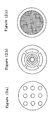
- Figure 3(a) to 3(d) are cross-sectional views showing major points of the forming jig of Figure 1, wherein Figure 3(a) is a cross-sectional view showing main parts along the line A-A, Figure 3(b) is a cross-sectional view showing main parts along the line B-B, Figure 3(c) is a cross-sectional view showing main parts along the line C-C, and Figure 3(d) is a cross-sectional view showing main parts along the line D-D.
- the basic configuration of the forming jig of the present invention comprises a rectification plate 4 having two or more material supply holes 2, a drawing die 5 installed below the rectification plate 4 to specify the external configuration of the formed body 20 produced from the material, and a floating die 10 in which two or more wires 8 (seven in Figure 2) float vertically in spaces 7 in the drawing die (forming pattern passages) and stretch from the exit section 6 of the drawing die 5 to form a hollow hole forming pattern.
- a fluid material supplied from two or more material supply holes 2 of the rectification plate 4 is introduced into the spaces 7 in the drawing die.
- Two or more wires 8 stretch from the material supply holes 2 to near the exit of the drawing die to homogenize the flow rate distribution of the fluid material and, at the same time, make the pressure applied to the wires 8 even.
- This configuration can reduce the cross-sectional area of the fluid while retaining the similarity of the figure from the upstream side to the downstream side of the tapered inner space 7 of the drawing die as shown in Figures 3(a) to 3(c).
- the fluid material is extruded from the exit section 6 of the drawing die having a predetermined forming pattern, whereby a (cylindrical) formed body 20 having hollow holes 22 (seven in Figure 3), as shown in Figure 3(d), can be formed.
- the manufacturing method of the formed body of the present invention may be varied according to the properties of the fluid material and the configuration of the formed body.
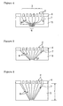
- the forming pattern may be varied by greatly narrowing the exit section of the drawing die 5 as compared with the entrance section 3, thereby sharply increasing the pressure of the fluid material, as shown in Figure 4. It is also possible to control the flow rate distribution of the fluid by changing the taper angle ⁇ as shown in Figure 5. Alternatively, it is possible to stabilize the forming pattern by expanding the distance t from the exit to the entrance of the drawing die and thereby slowing down the flow rate of the fluid as shown in Figure 6.
- a drawing die 13 provided with a cover-forming passage 12 around the pattern forming passage as shown in Figure 7(a), for example, is used to obtain a formed body 30 (a cylinder in Figure 7(b)) having a cover 34 (outer (peripheral) wall) with a prescribed thickness outside the forming pattern section 33 in which hollow holes 32 (seven in Figure 7(b)) are formed.
- the extrusion rate in the cover-forming passage 12 differs from the extrusion rate in the pattern forming passage 7 during extrusion molding of the fluid material, distortion and deficits may be produced in the outer cover 34 and the hollow hole 32 of the formed body 30 produced by extrusion.
- the fluid material is supplied separately to the cover-forming passage 12 and the pattern forming passage 7 as shown in Figure 7(a).
- a control plate 14 to control the balance between the amount of the material supplied to the cover-forming passage 12 and the amount of the material supplied to the pattern-forming passage 7 is installed on the upstream side of the rectification plate 4, whereby the cover 34 (outer (peripheral) wall) and the forming pattern section 33 are optimized.
- the fluid material A for the forming pattern section 33 and the fluid material B for the cover 34 (outer (peripheral) wall), shown in Figure 7(a), may be either the same material or different materials.
- the fluid materials A-C for each layer to be supplied to the material supply holes 2 in the rectification plate 4 may be distributed by the control plate 14 to obtain a laminate 40 (a hexagonal prism in Figure 8(b)) consisting of two or more layers (three layers in Figure 8(b)) from different materials and having a plurality of hollow holes 42 as shown in Figure 8(b).
- control plate 14 not only prevents dislocation of the interface of each layer in the laminate, but also prevents the surface of the formed laminated body from becoming wrinkled or distorted.
- the fluid materials to be supplied to each material passage 2 are preferably separated by a material distributor 15 and the forming jig is preferably optimized to balance the amount of the material to be supplied to each material passage 2.
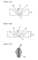
- a formed body 60 with a deformed external configuration and hollow holes 62 as shown in Figure 10(c) by, for example, extruding a raw material first in the manner as shown in Figure 10(a) and then, at an arbitrary point of time, varying the exit section 6 of the drawing die 19 to either sides as shown in Figure 10(b).
- a formed body 70 with a further unique configuration can be obtained by varying not only the exit section 6 of the drawing die 19, but also the positions of floating-type movable wires 18 as shown in Figures 11(a), 11(b), and 11(c).
- the forming jig and the method for producing a formed body using the jig can be particularly suitably used for extrusion molding of a cylindrical object with holes in the form of fine straight lines formed at a high density (rod-like body with fine linear holes), for example, a body having an external configuration with a cross-sectional dimension in terms of the diameter of 0.1-1,000 mm, hollow holes with a cross-sectional size in terms of the diameter of 0.001-990 mm, and a hollow hole density of 0.000001-100,000 holes/mm 2 .
- the drawing die used in the present invention defines the external configuration (outline) of the formed body.
- the cross-sectional shape of the drawing die There are no specific limitations to the cross-sectional shape of the drawing die.
- a circle, square, triangle, hexagon, star, or (complicated) variant form can be appropriately selected according to the application, for example.
- the drawing die used in the present invention preferably has a tapered internal shape to control the flow rate distribution or slow down the flow rate of the fluid material during extrusion molding, thereby stabilizing the forming pattern.
- one extrusion unit can form various formed bodies conforming to applications.
- the drawing die used in the present invention may have a cover-forming passage to form an outer peripheral wall.
- a cover-forming passage to form an outer peripheral wall.
- the floating die used in the present invention has one or more wires floating vertically in the drawing die and stretching from the exit section of the drawing die to form a hollow hole forming pattern. This is installed on the upstream side ( Figures 1 and 2) or the downstream side ( Figures 4-6) of the rectification plate.
- a floating die excelling in wear resistance, being flexibly deformed in accordance with a flow of the material, and exhibiting almost no deformation in the exit section is preferably used in the present invention (see Figure 1).
- the floating die used in the present invention is preferably formed from wires having rigidities corresponding to the flowability of the material and/or the forming pattern.
- the floating die used in the present invention is preferably connected with two or more wires on the upstream and downstream sides of the rectification plate and secured by welding or using an adhesive or a fixing jig.
- the floating die may be combined with a partly variable floating die (see Figure 11(a)(b)(c)).
- the rectification plate used in the present invention has two or more material supply holes which divide the drawing die into spaces (passages) or control the flow of a part of the fluid materials in the passages.
- the configuration of the rectification plate includes, but is not limited to, a multi-hole structure in which the holes in the shape of a rectangle, hexagon, or circle are arranged (see Figure 12(a)), a unique-hole structure (see Figure 12(b)), and a mesh structure (see Figure 12(c)). An appropriate type is selected from these types.
- the rectification plate used in the present invention may be provided with a diffuser 56 on the downstream side as shown in Figure 13(a) to clearly control the boundaries 55 of the layers (A-C) during multi-layer extrusion forming (see Figure 13(b)) as compared with the rectification plate without a diffuser (see Figures 14(a) and 14(b)).
- the rectification plate of the present invention is usually used in combination with a control plate to respond to various flow patterns.
- the wire used in the present invention guides the fluid material in the direction in which the wires are projecting and controls the fluidity of the material in the same direction, thereby determining the shape of hollow holes during extrusion forming.
- wires there are no specific limitations to the configuration of the wires used. Beside common-type wires, a wire with a uniquely shaped part on the tip (unique shape wire) and a type suspending a uniquely shaped body using two or more wires (a floating die) can be used.
- the unique shape wire used in the present invention may comprise a uniquely shaped component 82 attached to the tip of the wire base 81 with a clasp 83 as shown, for example, in Figure 15(a). Since the uniquely shaped component 82 may have an optional cross-sectional configuration as shown in Figures 15(b) to 15(d), not only is it possible to easily modify the floating die and to coat the floating die for providing wear resistance, but also it is possible to determine positions by adjusting a surrounding flowability.
- a hard material (including a superhard alloy) is preferably used as the uniquely shaped component 82 in view of wear resistance.
- the thickness of the floating die can be reduced as shown in Figures 16(a), 16(b), and 16(c), for example. Not only can the molding pressure loss be reduced, but also the length of wires 8 can be adjusted using clamps 84, whereby it is possible to adjust the fluidity balance.
- floating dies 86 and 88 used in the present invention may be worked into any optional form by laser beams or wire discharges, formed from a wear resistant material or ultrahard alloy, or provided with coating for ease of maintenance by washing and the like.
- the cross-sectional configuration of the wire used in the present invention may be appropriately selected in accordance with the application from a circle, square, triangle, hexagon, star, and variant forms.
- the material of the wire used in the present invention is preferably nylon 66.
- a rectification plate with 127 holes, each having a diameter of 1.0 mm, arranged in the shape of a hexagon on a SUS plate with a diameter of 20 mm was placed on a drawing die having a tapered exit in the shape of a nozzle with a diameter of 2.0 mm.
- a floating die with 19 wires made of nylon 66, each having a diameter of 0.2 mm, arranged in the shape of a hexagon was installed on the rectification plate with the wires being drawn out to the exit of the drawing die.
- the clay mixture was charged into the cylinder.
- the clay mixture was extruded at a rate of 10 mm/sec using a piston, while cutting the extruded product to a length about 100 mm.
- the extruded material was dried in a dryer at a temperature of 120°C for 10 minutes to obtain a formed body (a dry body) having an external diameter of 2.1 mm and 19 holes with a diameter of 0.2 mm (see Figure 17).
- the formed body was heated to 200°C in one hour, maintained at 200°C for one hour, heated to 300°C in one hour, heated to 1,600°C in six hours, and sintered at 1,600°C for two hours.
- the sintered body was allowed to cool to room temperature.
- Both end surfaces of the resulting sintered body was finished with a file and polish wastes were removed to obtain a complete body.
- the obtained complete body was cut in every 5 mm interval to observe the cross-section to confirm that all holes were intact with neither adhesion to adjacent holes nor clogging.
- the forming jig and the method for producing a formed body using the jig of the present invention can easily and inexpensively design or change the design of a forming pattern of hollow holes and the external configuration of the formed body, and can form fine hollow holes at a high density.
- the forming jig and the method for producing a formed body using the jig of the present invention can achieve a great contribution to a wide spectrum of applications such as a column for chromatograph, ceramic filter, high speed heat exchanger, small reactor, metal composite material, cell structure object for fuel cells, separator, ink-jet nozzle, ceramic die, spinning die, burner nozzle, multi-channel liquid feed passage, lightweight ceramic component, heat insulating ceramic material, optical connector ferrule, and kitchen instrument such as pasta extruder.
- a forming jig comprises a rectification plate having two or more material supply holes, a drawing die installed below the rectification plate to specify the external configuration of the formed body produced from a material, and a floating die in which two or more wires float vertically in spaces in the drawing die (forming pattern passages) and stretch from the exit section of the drawing die to form a hollow hole forming pattern.
- the forming jig and a method for producing a formed body using the jig can easily and inexpensively design or change the design of a forming pattern of hollow holes and the external configuration of the formed body and can form fine hollow holes at a high density.
Landscapes
- Engineering & Computer Science (AREA)
- Mechanical Engineering (AREA)
- Manufacturing & Machinery (AREA)
- Chemical & Material Sciences (AREA)
- Ceramic Engineering (AREA)
- Extrusion Moulding Of Plastics Or The Like (AREA)
- Press-Shaping Or Shaping Using Conveyers (AREA)
- Shaping Metal By Deep-Drawing, Or The Like (AREA)
- Metal Extraction Processes (AREA)
Abstract
Description
- The present invention relates to a forming jig and a method for producing a formed body using the jig.
- As a method for producing a hollow rod-like body having an optional form and one or more hollow holes from ceramics, metals, or carbon, a method of forming a hollow rod-like body by press molding, cast molding, injection molding, rubber-press method, hot plate press method, or the like, and sintering the molded object or a method of providing a sintered object (rod-like body) with a certain external appearance and drilling a hollow hole through the sintered object by drill processing, electrical discharge machining, electrochemical processing (ECM processing), or the like has been employed.
- These methods, however, involve a very complicated process and technical difficulty, resulting in poor productivity. This tendency is particularly conspicuous when narrowing the size of holes or producing hollow holes at a high density.
- For this reason, a method of producing a hollow rod-like body (including a honeycomb structural object) having one or more hollow holes by forming a hollow extrusion material by extrusion molding using a special die or a special mouthpiece and sintering the extruded object has been mainly employed in recent years.
- This method was successful in greatly improving productivity and optionally selecting the form and number of hollow holes by using a die.
- However, since a material with a comparatively low viscosity is used in this method, the hollow holes are easily collapsed after extrusion molding. It has been difficult to constantly maintain a good quality. In particular, to produce a hollow rod-like body (including a honeycomb structural object) having fine hollow holes at a high density has been difficult due to the structure of dies. An additional problem has been a high production cost due to easily worn-out and very expensive dies.
- To overcome the above problems, a method for producing a cellular honeycomb has been proposed. The method described in Published Japanese Translation of PCT Publication for Patent Application No. 2001-526129, for example, comprises providing a cellular structure object (honeycomb structure object) containing two or more parallel channels having a predetermined section, filling the channels with a filler, and remodeling the cellular honeycomb structure by narrowing with a taper.
- A method for producing a hollow rod-like body with a porous structure has been proposed in Japanese Patent Application Laid-open No. 2001-247372, for example. The method comprises producing thin hollow rods of ceramic of which the hollow space is packed with a filler, bundling a plurality of such hollow rods and remodelling the bundled rods to form a bundle (optionally, again bundling the formed bundles and remodeling the rebundled objects), and extruding the bundle using a die and a plunger.
- Another method that has been proposed by, for example, Japanese Patent Application Laid-open No. 6-264105, produces a body to be sintered having a helical hole inside the section and a twist groove in the outer circumference. The method comprises extruding a kneaded plastic material from an extruder and causing the extruded material to pass through a torsion-imparting device and then through a metal die to obtain the body to be sintered.
- The method of Published Japanese Translation of PCT Publication for Patent Application No. 2001-526129 requires a step of packing and removing the filler after preparing a cellular structural object (honeycomb structural object), giving rise to an increase in the manufacturing cost for the filler and the die for the honeycomb structural object.
- The method of Japanese Patent Application Laid-open No. 2001-247372 has a problem of difficulty in producing rod-like bodies with fine linear holes for fabricating the hollow rod-like body with a porous structure. The method also requires a complicated procedure for remodeling and cannot produce cells at a high density.
- The method of Japanese Patent Application Laid-open No. 6-264105 can produce a hollow structure by extrusion molding, but can neither produce holes at a high density nor arrange the holes in a desired pattern. An additional problem with this method is a high mandrel production cost.
- The present invention has been completed in view of the problems in the prior art mentioned above and has an object of providing a forming jig which can easily and inexpensively design or change the design of a forming pattern of hollow holes and the external configuration of a formed body, and can form fine hollow holes at a high density, and a method for producing a formed body using the jig.
- Specifically, the present invention provides a forming jig comprising a rectification plate having two or more material supply holes, a drawing die installed below the rectification plate to define the external configuration of the formed body produced from a material, and a floating die in which one or more wires float vertically in the drawing die floating and stretch the exit section of the drawing die to form a hollow hole forming pattern.
- In the above-described forming jig, the floating die is preferably installed on the upstream side or downstream side of the rectification plate and has one or more wires secured thereto.
- It is desirable that the drawing die used in the present invention satisfy any one of the conditions (1)-(3):
- (1) a tapered internal configuration,
- (2) a freely variable exit section, and
- (3) a cover-forming passage for forming an outer (peripheral) wall.
-
- It is desirable that the floating die used in the present invention excel in wear resistance, can be flexibly deformed in accordance with a flow of the material, and exhibit almost no deformation in the exit section.
- The floating die of the present invention is preferably connected with two or more wires on the upstream and downstream sides of the rectification plate and secured by welding or using an adhesive or a fixing jig. In addition, the floating die used in the present invention is preferably formed from wires having rigidities corresponding to the flowability of the material and/or the forming pattern.
- The present invention further provides a method for producing a formed body comprising introducing a fluid material supplied from two or more material supply holes of a rectification plate into a drawing die, homogenizing the flow rate distribution of the fluid material in the drawing die using one or more wires stretched from the material supply holes to near the exit section of the drawing die, and extruding the fluid material from the exit section of the drawing die in which a prescribed forming pattern is formed by two or more wires, thereby causing the one or more wires to form hollow holes through the formed body.
- It is desirable that the method for forming a formed body of the present invention satisfy any one of the following conditions (1)-(4).
- (1) The drawing die has a tapered shape to control the flow rate distribution or slow down the flow rate of the fluid material, thereby stabilizing the forming pattern.
- (2) The exit section of the drawing die is freely variable to change the external configuration and size of the formed body and hollow holes.
- (3) The drawing die is provided with a cover-forming passage for forming an outer (peripheral) wall on the outermost (peripheral) side thereof to produce a formed body with an outer (peripheral) wall.
- (4) The formed body is a laminate comprising multiple layers, each layer being formed from a fluid material different from that of adjacent layers, wherein a fluid material corresponding to each layer is introduced into each material supply hole in the rectification plate.
- The formed body produced by the above method is preferably a hollow rod-like body with fine linear holes.
- The hollow rod-like body with fine linear holes preferably has a cross-sectional dimension, in terms of diameter, of 0.1-1,000 mm. In addition, the rod-like body with fine linear holes preferably has a hollow hole density of 0.000001-100,000 holes/mm2.
-
- Figure 1 is a longitudinal sectional view schematically showing an embodiment of the forming jig of the present invention.
- Figure 2 is a schematic front view of Figure 1.
- Figure 3(a) to 3(d) are cross-sectional views showing major points of the forming jig of Figure 1, wherein Figure 3(a) is a cross-sectional view showing main parts along the line A-A, Figure 3(b) is a cross-sectional view showing main parts along the line B-B, Figure 3(c) is a cross-sectional view showing main parts along the line C-C, and Figure 3(d) is a cross-sectional view showing main parts along the line D-D.
- Figure 4 is another longitudinal sectional view schematically showing an embodiment of the forming jig of the present invention.
- Figure 5 is still another longitudinal sectional view schematically showing an embodiment of the forming jig of the present invention.
- Figure 6 is yet another longitudinal sectional view schematically showing an embodiment of the forming jig of the present invention.
- Figure 7(a)(b) show an embodiment of the method for producing the formed body (with an outer (peripheral) wall) of the present invention, wherein Figure 7(a) is a schematic longitudinal sectional view and Figure 7(b) shows a sectional view of a main part of the formed body with an outer (peripheral) wall.
- Figure 8 (a) (b) show another embodiment of the method for producing the formed body (multi-layer extrusion) of the present invention, wherein Figure 8(a) is a schematic longitudinal sectional view and Figure 8(b) shows a sectional view of a main part of the formed laminated body.
- Figure 9(a)(b) show still another embodiment of the method for producing the formed body (multi-layer extrusion) of the present invention, wherein Figure 9(a) is a schematic longitudinal sectional view and Figure 9(b) shows a sectional view of a main part of the formed laminated body.
- Figure 10(a)(b)(c) show a further embodiment of the method for producing the formed body (using a variable drawing die) of the present invention, wherein Figure 10(a) is a schematic longitudinal sectional view under normal conditions, Figure 10(b) shows a schematic longitudinal sectional view under the conditions in which the variable drawing die is expanded to either side, and Figure 10(c) shows a longitudinal sectional view of the resulting formed body.
- Figure 11(a)(b)(c) show a further embodiment of the method for producing the formed body (using a variable drawing die and a variable floating die) of the present invention, wherein Figure 11(a) is a schematic longitudinal sectional view under normal conditions, Figure 11(b) shows a schematic longitudinal sectional view under the conditions in which the variable drawing die and variable floating die are expanded to either side, and Figure 11(c) shows a longitudinal sectional view of the resulting formed body.
- Figure 12(a)(b)(c) are schematic front views showing examples of the rectification plate used in the present invention.
- Figure 13(a)(b) show an embodiment of the rectification plate (with a diffuser) used in the present invention viewed from the back, wherein Figure 13(a) is a schematic longitudinal sectional view and Figure 13(b) shows a sectional view of the main part of the formed laminated body.
- Figure 14(a)(b) show another embodiment of the rectification plate (without a diffuser) used in the present invention viewed from the back, wherein Figure 14(a) is a schematic longitudinal sectional view and Figure 14(b) shows a sectional view of the main part of the formed laminated body.
- Figure 15(a)(b)(c)(d) are longitudinal sectional views of examples of the unique shape wire used in the present invention, wherein Figure 15(a) shows the manner in which the uniquely shaped part is attached, Figure 15(b) shows a right-angled uniquely shaped part, Figure 15(c) a cone-type uniquely shaped part, and Figure 15(d) a low head-type uniquely shaped part.
- Figure 16(a)(b)(c) show an embodiment of the floating die used in the present invention, wherein Figure 16(a) is a schematic longitudinal sectional view, Figure 16(b) shows a front view of the exit, and Figure 16(c) is a sectional view of the main part of the formed body.
- Figure 17 is a sectional view of the main part of the formed body obtained in the example.
-
- The forming jig of the present invention comprises a rectification plate having two or more material supply holes, a drawing die installed below the rectification plate to define the external configuration of the formed body produced from a material, and a floating die in which one or more wires float vertically in the drawing die floating and stretch from the exit section of the drawing die to form a hollow hole forming pattern.
- In the above-described forming jig, the floating die is preferably installed on the upstream side or downstream side of the rectification plate and has one or more wires secured thereto.
- The method for producing a formed body using the above-described forming jig comprises introducing a fluid material supplied from two or more material supply holes of a rectification plate into a drawing die, homogenizing the flow rate distribution of the fluid material in the drawing die using two or more wires stretched from the material supply holes to near the exit section of the drawing die, and extruding the fluid material from the exit section of the drawing die in which a prescribed forming pattern is formed by two or more wires, thereby causing the one or more wires to form hollow holes through the formed body.
- Due to the above-described constitution, the forming jig of the present invention can easily and inexpensively design or change the design of a forming pattern of hollow holes and the external configuration of the formed body without requiring a precision process using a conventional die or mouth ring. Furthermore, since the floating die and the drawing die are basically formed from separate and independent members, these dies can be maintained more easily and inexpensively than conventional dies or mouthpieces when worn out due to fluid materials.
- In addition, since the flow rate distribution of the fluid material in the drawing die can be homogenized by one or more wires stretched from the material supply holes to near the exit section of the drawing die, not only can quality and precision of the formed body be improved, but also fluctuation of the quality of the formed bodies can be minimized (or the yield of the products can be increased).
- Moreover, since hollow holes in the formed body are produced by wires in the forming jig of the present invention, a rod-like body with fine linear hollow holes or a formed body with fine hollow holes at a high density can be produced easily and inexpensively without requiring complicated steps as in conventional methods (see, for example, Published Japanese Translation of PCT Publication for Patent Application No. 2001-526129 and Japanese Patent Application Laid-open No. 2001-247372).
- An embodiment of the present invention will be described below in detail referring to the drawings.
- Figure 1 is a longitudinal sectional view schematically showing an embodiment of the forming jig of the present invention. Figure 2 is a schematic front view of Figure 1. Figure 3(a) to 3(d) are cross-sectional views showing major points of the forming jig of Figure 1, wherein Figure 3(a) is a cross-sectional view showing main parts along the line A-A, Figure 3(b) is a cross-sectional view showing main parts along the line B-B, Figure 3(c) is a cross-sectional view showing main parts along the line C-C, and Figure 3(d) is a cross-sectional view showing main parts along the line D-D.
- As shown in Figure 1 and Figure 2, the basic configuration of the forming jig of the present invention comprises a
rectification plate 4 having two or morematerial supply holes 2, a drawing die 5 installed below therectification plate 4 to specify the external configuration of the formedbody 20 produced from the material, and a floatingdie 10 in which two or more wires 8 (seven in Figure 2) float vertically inspaces 7 in the drawing die (forming pattern passages) and stretch from theexit section 6 of the drawing die 5 to form a hollow hole forming pattern. - As shown in Figure 1, when a formed
body 20 is manufactured using the forming jig, a fluid material supplied from two or morematerial supply holes 2 of therectification plate 4 is introduced into thespaces 7 in the drawing die. Two or more wires 8 (seven in Figure 1) stretch from thematerial supply holes 2 to near the exit of the drawing die to homogenize the flow rate distribution of the fluid material and, at the same time, make the pressure applied to thewires 8 even. This configuration can reduce the cross-sectional area of the fluid while retaining the similarity of the figure from the upstream side to the downstream side of the taperedinner space 7 of the drawing die as shown in Figures 3(a) to 3(c). The fluid material is extruded from theexit section 6 of the drawing die having a predetermined forming pattern, whereby a (cylindrical) formedbody 20 having hollow holes 22 (seven in Figure 3), as shown in Figure 3(d), can be formed. - In this instance, the manufacturing method of the formed body of the present invention may be varied according to the properties of the fluid material and the configuration of the formed body. For example, the forming pattern may be varied by greatly narrowing the exit section of the drawing die 5 as compared with the
entrance section 3, thereby sharply increasing the pressure of the fluid material, as shown in Figure 4. It is also possible to control the flow rate distribution of the fluid by changing the taper angle as shown in Figure 5. Alternatively, it is possible to stabilize the forming pattern by expanding the distance t from the exit to the entrance of the drawing die and thereby slowing down the flow rate of the fluid as shown in Figure 6. - In the method for manufacturing the formed body of the present invention, a drawing die 13 provided with a cover-forming
passage 12 around the pattern forming passage as shown in Figure 7(a), for example, is used to obtain a formed body 30 (a cylinder in Figure 7(b)) having a cover 34 (outer (peripheral) wall) with a prescribed thickness outside the formingpattern section 33 in which hollow holes 32 (seven in Figure 7(b)) are formed. - In this instance, if the extrusion rate in the cover-forming
passage 12 differs from the extrusion rate in thepattern forming passage 7 during extrusion molding of the fluid material, distortion and deficits may be produced in theouter cover 34 and thehollow hole 32 of the formedbody 30 produced by extrusion. For this reason, the fluid material is supplied separately to the cover-formingpassage 12 and thepattern forming passage 7 as shown in Figure 7(a). At the same time, acontrol plate 14 to control the balance between the amount of the material supplied to the cover-formingpassage 12 and the amount of the material supplied to the pattern-formingpassage 7 is installed on the upstream side of therectification plate 4, whereby the cover 34 (outer (peripheral) wall) and the formingpattern section 33 are optimized. - The fluid material A for the forming
pattern section 33 and the fluid material B for the cover 34 (outer (peripheral) wall), shown in Figure 7(a), may be either the same material or different materials. - In addition, in the method for manufacturing the formed body of the present invention, as shown in Figure 8(a), for example, the fluid materials A-C for each layer to be supplied to the
material supply holes 2 in therectification plate 4 may be distributed by thecontrol plate 14 to obtain a laminate 40 (a hexagonal prism in Figure 8(b)) consisting of two or more layers (three layers in Figure 8(b)) from different materials and having a plurality ofhollow holes 42 as shown in Figure 8(b). - In this instance, the
control plate 14 not only prevents dislocation of the interface of each layer in the laminate, but also prevents the surface of the formed laminated body from becoming wrinkled or distorted. For this reason, the fluid materials to be supplied to eachmaterial passage 2 are preferably separated by amaterial distributor 15 and the forming jig is preferably optimized to balance the amount of the material to be supplied to eachmaterial passage 2. - When a formed laminated body 50 (a quadratic prism in Figure 9(b)) having
hollow holes 52 located along theinterface 54 of each layer (two layers in Figure 9(b)) is desired, such a product can be obtained by installing a floatingwire 8 on the interface and closing thematerial supply holes 2 by thecontrol plate 14 as shown in Figure 9(a). - In addition, according to the method for fabricating a formed body of the present invention, it is possible to obtain a formed
body 60 with a deformed external configuration andhollow holes 62 as shown in Figure 10(c) by, for example, extruding a raw material first in the manner as shown in Figure 10(a) and then, at an arbitrary point of time, varying theexit section 6 of the drawing die 19 to either sides as shown in Figure 10(b). - At this time, a formed
body 70 with a further unique configuration (see Figure 11(c)) can be obtained by varying not only theexit section 6 of the drawing die 19, but also the positions of floating-typemovable wires 18 as shown in Figures 11(a), 11(b), and 11(c). - The forming jig and the method for producing a formed body using the jig can be particularly suitably used for extrusion molding of a cylindrical object with holes in the form of fine straight lines formed at a high density (rod-like body with fine linear holes), for example, a body having an external configuration with a cross-sectional dimension in terms of the diameter of 0.1-1,000 mm, hollow holes with a cross-sectional size in terms of the diameter of 0.001-990 mm, and a hollow hole density of 0.000001-100,000 holes/mm2.
- Major components of the forming jig of the present invention will now be explained in detail.
- The drawing die used in the present invention defines the external configuration (outline) of the formed body. There are no specific limitations to the cross-sectional shape of the drawing die. A circle, square, triangle, hexagon, star, or (complicated) variant form can be appropriately selected according to the application, for example.
- The drawing die used in the present invention preferably has a tapered internal shape to control the flow rate distribution or slow down the flow rate of the fluid material during extrusion molding, thereby stabilizing the forming pattern.
- Since the drawing die used in the present invention has a freely variable exit section that can change the dimension (external and internal dimensions) of the formed body, one extrusion unit can form various formed bodies conforming to applications.
- The drawing die used in the present invention may have a cover-forming passage to form an outer peripheral wall. Either an integral type as shown in Figure 7 (a) or a type provided with a separate cover-forming passage which can be combined with a common drawing die can be used.
- The floating die used in the present invention has one or more wires floating vertically in the drawing die and stretching from the exit section of the drawing die to form a hollow hole forming pattern. This is installed on the upstream side (Figures 1 and 2) or the downstream side (Figures 4-6) of the rectification plate.
- A floating die excelling in wear resistance, being flexibly deformed in accordance with a flow of the material, and exhibiting almost no deformation in the exit section is preferably used in the present invention (see Figure 1).
- In addition, the floating die used in the present invention is preferably formed from wires having rigidities corresponding to the flowability of the material and/or the forming pattern.
- For example, it is possible to control escape of a fluid material from near the internal surface of the drawing die by providing the wire near the internal surface of the drawing die with a high rigidity. The external configuration of the resulting formed body can be excellently maintained in this manner.
- The floating die used in the present invention is preferably connected with two or more wires on the upstream and downstream sides of the rectification plate and secured by welding or using an adhesive or a fixing jig. The floating die may be combined with a partly variable floating die (see Figure 11(a)(b)(c)).
- The rectification plate used in the present invention has two or more material supply holes which divide the drawing die into spaces (passages) or control the flow of a part of the fluid materials in the passages. The configuration of the rectification plate includes, but is not limited to, a multi-hole structure in which the holes in the shape of a rectangle, hexagon, or circle are arranged (see Figure 12(a)), a unique-hole structure (see Figure 12(b)), and a mesh structure (see Figure 12(c)). An appropriate type is selected from these types.
- The rectification plate used in the present invention may be provided with a
diffuser 56 on the downstream side as shown in Figure 13(a) to clearly control theboundaries 55 of the layers (A-C) during multi-layer extrusion forming (see Figure 13(b)) as compared with the rectification plate without a diffuser (see Figures 14(a) and 14(b)). - In addition, the rectification plate of the present invention is usually used in combination with a control plate to respond to various flow patterns.
- The wire used in the present invention guides the fluid material in the direction in which the wires are projecting and controls the fluidity of the material in the same direction, thereby determining the shape of hollow holes during extrusion forming.
- There are no specific limitations to the configuration of the wires used. Beside common-type wires, a wire with a uniquely shaped part on the tip (unique shape wire) and a type suspending a uniquely shaped body using two or more wires (a floating die) can be used.
- The unique shape wire used in the present invention may comprise a uniquely shaped
component 82 attached to the tip of thewire base 81 with aclasp 83 as shown, for example, in Figure 15(a). Since the uniquely shapedcomponent 82 may have an optional cross-sectional configuration as shown in Figures 15(b) to 15(d), not only is it possible to easily modify the floating die and to coat the floating die for providing wear resistance, but also it is possible to determine positions by adjusting a surrounding flowability. - A hard material (including a superhard alloy) is preferably used as the uniquely shaped
component 82 in view of wear resistance. - In the present invention, the thickness of the floating die can be reduced as shown in Figures 16(a), 16(b), and 16(c), for example. Not only can the molding pressure loss be reduced, but also the length of
wires 8 can be adjusted usingclamps 84, whereby it is possible to adjust the fluidity balance. - Moreover, the floating dies 86 and 88 used in the present invention may be worked into any optional form by laser beams or wire discharges, formed from a wear resistant material or ultrahard alloy, or provided with coating for ease of maintenance by washing and the like.
- The cross-sectional configuration of the wire used in the present invention may be appropriately selected in accordance with the application from a circle, square, triangle, hexagon, star, and variant forms.
- Although there are no specific limitations to the material of the wire used in the present invention inasmuch as the material has excellent wear resistance and provides the wire with an appropriate rigidity, the material is preferably nylon 66.
- The present invention is described below in more detail by examples. However, the present invention is not limited the following examples.
- 10 parts by weight of methylcellulose as a binder was added to 100 parts by weight of alumina particles with an average particle diameter of 10 µm. The mixture was kneaded using a kneader to produce a clay mixture.
- A rectification plate with 127 holes, each having a diameter of 1.0 mm, arranged in the shape of a hexagon on a SUS plate with a diameter of 20 mm was placed on a drawing die having a tapered exit in the shape of a nozzle with a diameter of 2.0 mm.
- A floating die with 19 wires made of nylon 66, each having a diameter of 0.2 mm, arranged in the shape of a hexagon was installed on the rectification plate with the wires being drawn out to the exit of the drawing die.
- After installing a cylinder in front of the rectification plate, the clay mixture was charged into the cylinder. The clay mixture was extruded at a rate of 10 mm/sec using a piston, while cutting the extruded product to a length about 100 mm. The extruded material was dried in a dryer at a temperature of 120°C for 10 minutes to obtain a formed body (a dry body) having an external diameter of 2.1 mm and 19 holes with a diameter of 0.2 mm (see Figure 17).
- The formed body was heated to 200°C in one hour, maintained at 200°C for one hour, heated to 300°C in one hour, heated to 1,600°C in six hours, and sintered at 1,600°C for two hours. The sintered body was allowed to cool to room temperature.
- Both end surfaces of the resulting sintered body was finished with a file and polish wastes were removed to obtain a complete body.
- The obtained complete body was cut in every 5 mm interval to observe the cross-section to confirm that all holes were intact with neither adhesion to adjacent holes nor clogging.
- As discussed above, the forming jig and the method for producing a formed body using the jig of the present invention can easily and inexpensively design or change the design of a forming pattern of hollow holes and the external configuration of the formed body, and can form fine hollow holes at a high density.
- The forming jig and the method for producing a formed body using the jig of the present invention can achieve a great contribution to a wide spectrum of applications such as a column for chromatograph, ceramic filter, high speed heat exchanger, small reactor, metal composite material, cell structure object for fuel cells, separator, ink-jet nozzle, ceramic die, spinning die, burner nozzle, multi-channel liquid feed passage, lightweight ceramic component, heat insulating ceramic material, optical connector ferrule, and kitchen instrument such as pasta extruder.
A forming jig comprises a rectification plate having two or more material supply holes, a drawing die installed below the rectification plate to specify the external configuration of the formed body produced from a material, and a floating die in which two or more wires float vertically in spaces in the drawing die (forming pattern passages) and stretch from the exit section of the drawing die to form a hollow hole forming pattern. The forming jig and a method for producing a formed body using the jig can easily and inexpensively design or change the design of a forming pattern of hollow holes and the external configuration of the formed body and can form fine hollow holes at a high density.
Claims (17)
- A forming jig comprising:a rectification plate having two or more material supply holes,a drawing die installed below the rectification plate to define the outward configuration of the formed body produced from a material, anda floating die in which one or more wires float vertically in the drawing die and stretch from the exit section of the drawing die to form a hollow hole forming pattern.
- The forming jig according to claim 1, wherein the floating die is installed on the upstream side or downstream side of the rectification plate and has one or more wires secured thereto.
- The forming jig according to claim 1 or 2, wherein the drawing die has a tapered internal shape.
- The forming jig according to any one of claims 1-3, wherein the drawing die has a freely variable exit section.
- The forming jig according to any one of claims 1-4, wherein the drawing die has a cover forming passage to form an outer (peripheral) wall.
- The forming jig according to any one of claims 1-5, wherein the floating die is a material excelling in wear resistance, being flexibly deformed in accordance with a fluid material, and exhibiting almost no deformation in the exit section of the drawing die.
- The forming jig according to any one of claims 1-6, wherein the floating die is connected with two or more wires on the upstream and downstream sides of the rectification plate and secured by welding or using an adhesive or a fixing jig.
- The forming jig according to any one of claims 1-7, wherein the floating die comprises the wires having rigidities corresponding to the flowability of the material and/or the forming pattern.
- A method for producing a formed body comprising:introducing a fluid material supplied from two or more material supply holes of a rectification plate into a drawing die,homogenizing the flow rate distribution of the fluid material in the drawing die using one or more wires stretched from the material supply holes to near the exit section of the drawing die, andextruding the fluid material from the exit section of the drawing die in which a prescribed forming pattern is formed by two or more wires,thereby causing the one or more wires to form hollow holes through the formed body.
- The method according to claim 9, wherein the drawing die has a tapered shape to control the flow rate distribution or slow down the flow rate of the fluid material, thereby stabilizing the forming pattern.
- The method according to claim 9 or 10, wherein the exit section of the drawing die is freely variable to change the external configuration and size of the formed body and hollow holes.
- The method according to any one of claims 9-11, wherein the drawing die is provided with a cover-forming passage for forming an outer (peripheral) wall on the outermost (peripheral) side thereof, whereby the resulting formed body has an outer (peripheral) wall.
- The method according to any one of claims 9-12, wherein the formed body is a laminate comprising multiple layers, each layer being formed from a fluid material different from that of adjacent layers, the method comprising introducing a fluid material corresponding to each layer into each material supply hole in the rectification plate.
- The method according to any one of claims 9-13, wherein the formed body is a rod-like body with fine linear holes.
- The method according to claim 14, wherein the hollow rod-like body with fine linear holes has a cross-sectional dimension, in terms of diameter, of 0.1-1,000 mm.
- The method according to claims 14 or 15, wherein the hollow rod-like body with fine linear holes has hollow holes with a cross-sectional dimension, in terms of diameter, of 0.001-990 mm.
- The method according to any one of claims 14-16, wherein the hollow rod-like body with fine linear holes has a hollow hole density of 0.000001-100,000 holes/mm2.
Applications Claiming Priority (2)
| Application Number | Priority Date | Filing Date | Title |
|---|---|---|---|
| JP2003141371 | 2003-05-20 | ||
| JP2003141371A JP4426210B2 (en) | 2003-05-20 | 2003-05-20 | Molding jig and method for producing molded body using the same |
Publications (3)
| Publication Number | Publication Date |
|---|---|
| EP1481779A2 true EP1481779A2 (en) | 2004-12-01 |
| EP1481779A3 EP1481779A3 (en) | 2010-07-07 |
| EP1481779B1 EP1481779B1 (en) | 2012-05-02 |
Family
ID=33128180
Family Applications (1)
| Application Number | Title | Priority Date | Filing Date |
|---|---|---|---|
| EP04011984A Expired - Lifetime EP1481779B1 (en) | 2003-05-20 | 2004-05-19 | Forming JIG and method for producing formed body using same |
Country Status (3)
| Country | Link |
|---|---|
| US (2) | US7396223B2 (en) |
| EP (1) | EP1481779B1 (en) |
| JP (1) | JP4426210B2 (en) |
Cited By (2)
| Publication number | Priority date | Publication date | Assignee | Title |
|---|---|---|---|---|
| EP1945583A4 (en) * | 2005-10-12 | 2012-05-02 | Adelaide Res & Innovation Pty | METHOD AND DEVICE FOR FORMING A MICRO-STRUCTURED FIBER |
| CN111645337A (en) * | 2019-03-04 | 2020-09-11 | 波音公司 | Tool assembly for manufacturing porous composite structures and related systems and methods |
Families Citing this family (2)
| Publication number | Priority date | Publication date | Assignee | Title |
|---|---|---|---|---|
| CN108283828B (en) * | 2018-03-14 | 2023-08-25 | 衢州市三诚化工有限公司 | Glycerol pressurized dilution device and dilution method thereof |
| JP7305695B2 (en) * | 2021-03-26 | 2023-07-10 | 日本碍子株式会社 | Method for manufacturing columnar honeycomb fired body |
Citations (6)
| Publication number | Priority date | Publication date | Assignee | Title |
|---|---|---|---|---|
| DE675280C (en) | 1936-05-07 | 1939-05-04 | Thomas Koidl | Device for the production of crack-free, smooth walls and webs having hollow stones on extrusion presses |
| GB1207952A (en) | 1966-07-06 | 1970-10-07 | Mini Of Technology | Improvements in or relating to extrusion apparatus |
| EP0248560A1 (en) | 1986-06-03 | 1987-12-09 | Imperial Chemical Industries Plc | Extrusion die |
| JPH032005B2 (en) | 1982-09-30 | 1991-01-14 | Babcock Hitachi Kk | |
| DE29624253U1 (en) | 1996-10-25 | 2001-09-20 | Konrad Friedrichs KG, 95326 Kulmbach | Device for the continuous extrusion of rods made of plastic raw material equipped with a helical inner channel |
| US20020098320A1 (en) | 2000-12-01 | 2002-07-25 | Beall Douglas M. | Method for extruding ceramic honeycombs |
Family Cites Families (16)
| Publication number | Priority date | Publication date | Assignee | Title |
|---|---|---|---|---|
| US1849431A (en) * | 1929-12-19 | 1932-03-15 | Mayhew Walter Herbert | Extruding die |
| US3778217A (en) * | 1963-10-31 | 1973-12-11 | Atomic Energy Commission | Extrusion die |
| US3540094A (en) * | 1966-04-04 | 1970-11-17 | Reinhard Hendrik Antoon Jansse | Device for extruding articles |
| US3905743A (en) * | 1971-11-09 | 1975-09-16 | Corning Glass Works | Extrusion apparatus for forming thin-walled honeycomb structures |
| US4413968A (en) * | 1982-03-11 | 1983-11-08 | Thiokol Corporation | Extrusion die metering device |
| JPS63141710A (en) | 1986-12-03 | 1988-06-14 | Toshiba Chem Corp | Manufacture of multilayer interconnection board |
| JPH032005A (en) * | 1989-05-31 | 1991-01-08 | Tokin Corp | Method for extrusion molding of powder mixture |
| DE8915137U1 (en) * | 1989-12-23 | 1990-02-08 | Röhm GmbH, 64293 Darmstadt | Extrusion nozzle for the production of hollow chamber panels |
| DE4120166C2 (en) * | 1991-06-19 | 1994-10-06 | Friedrichs Konrad Kg | Extrusion tool for producing a hard metal or ceramic rod with twisted inner holes |
| JPH06264105A (en) | 1993-03-12 | 1994-09-20 | Hitachi Metals Ltd | Torsional extrusion molding device and molding method for blank material to be sintered |
| US5906838A (en) * | 1993-12-13 | 1999-05-25 | The Quaker Oats Company | Symmetrical flow extrusion manifold |
| US6206675B1 (en) * | 1997-06-16 | 2001-03-27 | Bevier William E. | Extrusion die for the manufacture of monolithic adsorption tubes |
| JP5042404B2 (en) | 1997-12-19 | 2012-10-03 | コーニング インコーポレイテッド | Cellular honeycomb body and manufacturing method thereof |
| US6405974B1 (en) * | 1998-08-12 | 2002-06-18 | F. John Herrington | Ribbed core dual wall structure |
| JP2001247372A (en) | 2000-03-03 | 2001-09-11 | Pilot Precision Co Ltd | Hollow rod made of ceramic, metal or carbon and method for producing the same |
| US6572357B2 (en) * | 2001-02-27 | 2003-06-03 | Illinois Valley Holding Comany | Apparatus for manufacturing monolithic cross flow particulate traps |
-
2003
- 2003-05-20 JP JP2003141371A patent/JP4426210B2/en not_active Expired - Fee Related
-
2004
- 2004-05-06 US US10/839,156 patent/US7396223B2/en not_active Expired - Lifetime
- 2004-05-19 EP EP04011984A patent/EP1481779B1/en not_active Expired - Lifetime
-
2008
- 2008-04-21 US US12/106,501 patent/US7793529B2/en not_active Expired - Lifetime
Patent Citations (6)
| Publication number | Priority date | Publication date | Assignee | Title |
|---|---|---|---|---|
| DE675280C (en) | 1936-05-07 | 1939-05-04 | Thomas Koidl | Device for the production of crack-free, smooth walls and webs having hollow stones on extrusion presses |
| GB1207952A (en) | 1966-07-06 | 1970-10-07 | Mini Of Technology | Improvements in or relating to extrusion apparatus |
| JPH032005B2 (en) | 1982-09-30 | 1991-01-14 | Babcock Hitachi Kk | |
| EP0248560A1 (en) | 1986-06-03 | 1987-12-09 | Imperial Chemical Industries Plc | Extrusion die |
| DE29624253U1 (en) | 1996-10-25 | 2001-09-20 | Konrad Friedrichs KG, 95326 Kulmbach | Device for the continuous extrusion of rods made of plastic raw material equipped with a helical inner channel |
| US20020098320A1 (en) | 2000-12-01 | 2002-07-25 | Beall Douglas M. | Method for extruding ceramic honeycombs |
Cited By (3)
| Publication number | Priority date | Publication date | Assignee | Title |
|---|---|---|---|---|
| EP1945583A4 (en) * | 2005-10-12 | 2012-05-02 | Adelaide Res & Innovation Pty | METHOD AND DEVICE FOR FORMING A MICRO-STRUCTURED FIBER |
| CN111645337A (en) * | 2019-03-04 | 2020-09-11 | 波音公司 | Tool assembly for manufacturing porous composite structures and related systems and methods |
| CN111645337B (en) * | 2019-03-04 | 2023-09-19 | 波音公司 | Tool assemblies and related systems and methods for fabricating porous composite structures |
Also Published As
| Publication number | Publication date |
|---|---|
| US20080196470A1 (en) | 2008-08-21 |
| US20040232586A1 (en) | 2004-11-25 |
| EP1481779B1 (en) | 2012-05-02 |
| US7793529B2 (en) | 2010-09-14 |
| EP1481779A3 (en) | 2010-07-07 |
| JP2004345095A (en) | 2004-12-09 |
| US7396223B2 (en) | 2008-07-08 |
| JP4426210B2 (en) | 2010-03-03 |
Similar Documents
| Publication | Publication Date | Title |
|---|---|---|
| US5308568A (en) | Extrusion die and method | |
| US11059200B2 (en) | Honeycomb structure forming die and method of manufacturing honeycomb structure forming die | |
| US3905743A (en) | Extrusion apparatus for forming thin-walled honeycomb structures | |
| US5702659A (en) | Honeycomb extrusion die and methods | |
| US4687433A (en) | Die for extruding ceramic honeycomb structural bodies | |
| EP2261003B1 (en) | Die tooling for extruding tubular product | |
| US7793529B2 (en) | Method for producing a formed body using a forming jig | |
| JP2012530000A (en) | Extrusion die for forming extrudates with thick and thin walls | |
| US20110206896A1 (en) | Ceramic Honeycomb Body And Process For Manufacture | |
| CN107570546A (en) | A kind of Multifunctional extrusion mould structure and method | |
| CN108349110B (en) | Extrusion die for honeycomb bodies | |
| US4722819A (en) | Die and processes for manufacturing honeycomb structures | |
| EP0360590B1 (en) | A method and an apparatus for extruding ceramic multi-layer structural bodies | |
| WO2002058925A1 (en) | Method for extruding ceramic honeycombs | |
| CN103895208B (en) | Nano lamination composite extrusion equipment | |
| US6991450B1 (en) | Open cavity extrusion dies | |
| CN211757689U (en) | Mould of large-scale board class section bar of expanding | |
| CN1338369A (en) | Improved coextruder for forming multi-layer composite plastic pipe | |
| CN216191998U (en) | Forming die for preparing four-hole propellant powder | |
| CN103895207B (en) | A kind of nano-stack compound extruded equipment | |
| US5306457A (en) | Extrusion die and method | |
| US5499913A (en) | Device for producing honeycomb structural bodies | |
| CN2494752Y (en) | Improved coextrusion moulding apparatus for multilayer composite plastic pipe | |
| CN202887878U (en) | A self-centering extrusion die for wires and cables | |
| KR200369439Y1 (en) | Multi-hole dieset equipment for aluminum precision extrusion |
Legal Events
| Date | Code | Title | Description |
|---|---|---|---|
| PUAI | Public reference made under article 153(3) epc to a published international application that has entered the european phase |
Free format text: ORIGINAL CODE: 0009012 |
|
| AK | Designated contracting states |
Kind code of ref document: A2 Designated state(s): AT BE BG CH CY CZ DE DK EE ES FI FR GB GR HU IE IT LI LU MC NL PL PT RO SE SI SK TR |
|
| AX | Request for extension of the european patent |
Extension state: AL HR LT LV MK |
|
| PUAL | Search report despatched |
Free format text: ORIGINAL CODE: 0009013 |
|
| AK | Designated contracting states |
Kind code of ref document: A3 Designated state(s): AT BE BG CH CY CZ DE DK EE ES FI FR GB GR HU IE IT LI LU MC NL PL PT RO SE SI SK TR |
|
| AX | Request for extension of the european patent |
Extension state: AL HR LT LV MK |
|
| 17P | Request for examination filed |
Effective date: 20101216 |
|
| AKX | Designation fees paid |
Designated state(s): CH DE FR GB LI NL |
|
| 17Q | First examination report despatched |
Effective date: 20110728 |
|
| GRAP | Despatch of communication of intention to grant a patent |
Free format text: ORIGINAL CODE: EPIDOSNIGR1 |
|
| GRAS | Grant fee paid |
Free format text: ORIGINAL CODE: EPIDOSNIGR3 |
|
| GRAA | (expected) grant |
Free format text: ORIGINAL CODE: 0009210 |
|
| AK | Designated contracting states |
Kind code of ref document: B1 Designated state(s): CH DE FR GB LI NL |
|
| REG | Reference to a national code |
Ref country code: GB Ref legal event code: FG4D |
|
| REG | Reference to a national code |
Ref country code: CH Ref legal event code: NV Representative=s name: NOVAGRAAF INTERNATIONAL SA Ref country code: CH Ref legal event code: EP |
|
| REG | Reference to a national code |
Ref country code: NL Ref legal event code: T3 |
|
| REG | Reference to a national code |
Ref country code: DE Ref legal event code: R096 Ref document number: 602004037571 Country of ref document: DE Effective date: 20120628 |
|
| PLBE | No opposition filed within time limit |
Free format text: ORIGINAL CODE: 0009261 |
|
| STAA | Information on the status of an ep patent application or granted ep patent |
Free format text: STATUS: NO OPPOSITION FILED WITHIN TIME LIMIT |
|
| 26N | No opposition filed |
Effective date: 20130205 |
|
| REG | Reference to a national code |
Ref country code: DE Ref legal event code: R097 Ref document number: 602004037571 Country of ref document: DE Effective date: 20130205 |
|
| REG | Reference to a national code |
Ref country code: FR Ref legal event code: PLFP Year of fee payment: 13 |
|
| REG | Reference to a national code |
Ref country code: FR Ref legal event code: PLFP Year of fee payment: 14 |
|
| REG | Reference to a national code |
Ref country code: FR Ref legal event code: PLFP Year of fee payment: 15 |
|
| PGFP | Annual fee paid to national office [announced via postgrant information from national office to epo] |
Ref country code: NL Payment date: 20220420 Year of fee payment: 19 |
|
| PGFP | Annual fee paid to national office [announced via postgrant information from national office to epo] |
Ref country code: GB Payment date: 20220401 Year of fee payment: 19 Ref country code: FR Payment date: 20220408 Year of fee payment: 19 Ref country code: DE Payment date: 20220329 Year of fee payment: 19 |
|
| PGFP | Annual fee paid to national office [announced via postgrant information from national office to epo] |
Ref country code: CH Payment date: 20220421 Year of fee payment: 19 |
|
| REG | Reference to a national code |
Ref country code: DE Ref legal event code: R119 Ref document number: 602004037571 Country of ref document: DE |
|
| REG | Reference to a national code |
Ref country code: CH Ref legal event code: PL |
|
| REG | Reference to a national code |
Ref country code: NL Ref legal event code: MM Effective date: 20230601 |
|
| GBPC | Gb: european patent ceased through non-payment of renewal fee |
Effective date: 20230519 |
|
| PG25 | Lapsed in a contracting state [announced via postgrant information from national office to epo] |
Ref country code: LI Free format text: LAPSE BECAUSE OF NON-PAYMENT OF DUE FEES Effective date: 20230531 Ref country code: CH Free format text: LAPSE BECAUSE OF NON-PAYMENT OF DUE FEES Effective date: 20230531 |
|
| PG25 | Lapsed in a contracting state [announced via postgrant information from national office to epo] |
Ref country code: NL Free format text: LAPSE BECAUSE OF NON-PAYMENT OF DUE FEES Effective date: 20230601 |
|
| PG25 | Lapsed in a contracting state [announced via postgrant information from national office to epo] |
Ref country code: DE Free format text: LAPSE BECAUSE OF NON-PAYMENT OF DUE FEES Effective date: 20231201 Ref country code: GB Free format text: LAPSE BECAUSE OF NON-PAYMENT OF DUE FEES Effective date: 20230519 |
|
| PG25 | Lapsed in a contracting state [announced via postgrant information from national office to epo] |
Ref country code: FR Free format text: LAPSE BECAUSE OF NON-PAYMENT OF DUE FEES Effective date: 20230531 |