EP1481767A1 - Tool for extracting chain pins - Google Patents
Tool for extracting chain pins Download PDFInfo
- Publication number
- EP1481767A1 EP1481767A1 EP20040012504 EP04012504A EP1481767A1 EP 1481767 A1 EP1481767 A1 EP 1481767A1 EP 20040012504 EP20040012504 EP 20040012504 EP 04012504 A EP04012504 A EP 04012504A EP 1481767 A1 EP1481767 A1 EP 1481767A1
- Authority
- EP
- European Patent Office
- Prior art keywords
- pin
- extractor
- tip
- connecting pin
- pin extractor
- Prior art date
- Legal status (The legal status is an assumption and is not a legal conclusion. Google has not performed a legal analysis and makes no representation as to the accuracy of the status listed.)
- Granted
Links
Images




Classifications
-
- B—PERFORMING OPERATIONS; TRANSPORTING
- B25—HAND TOOLS; PORTABLE POWER-DRIVEN TOOLS; MANIPULATORS
- B25B—TOOLS OR BENCH DEVICES NOT OTHERWISE PROVIDED FOR, FOR FASTENING, CONNECTING, DISENGAGING, OR HOLDING
- B25B27/00—Hand tools, specially adapted for fitting together or separating parts or objects whether or not involving some deformation, not otherwise provided for
- B25B27/0071—Hand tools, specially adapted for fitting together or separating parts or objects whether or not involving some deformation, not otherwise provided for for bicycles
-
- B—PERFORMING OPERATIONS; TRANSPORTING
- B21—MECHANICAL METAL-WORKING WITHOUT ESSENTIALLY REMOVING MATERIAL; PUNCHING METAL
- B21L—MAKING METAL CHAINS
- B21L9/00—Making chains or chain links, the links being composed of two or more different parts, e.g. drive chains
- B21L9/02—Making chains or chain links, the links being composed of two or more different parts, e.g. drive chains of roller-chain or other plate-link type
- B21L9/06—Sorting, feeding, assembling, riveting, or finishing parts of chains
- B21L9/065—Assembling or disassembling
-
- Y—GENERAL TAGGING OF NEW TECHNOLOGICAL DEVELOPMENTS; GENERAL TAGGING OF CROSS-SECTIONAL TECHNOLOGIES SPANNING OVER SEVERAL SECTIONS OF THE IPC; TECHNICAL SUBJECTS COVERED BY FORMER USPC CROSS-REFERENCE ART COLLECTIONS [XRACs] AND DIGESTS
- Y10—TECHNICAL SUBJECTS COVERED BY FORMER USPC
- Y10T—TECHNICAL SUBJECTS COVERED BY FORMER US CLASSIFICATION
- Y10T29/00—Metal working
- Y10T29/53—Means to assemble or disassemble
- Y10T29/53796—Puller or pusher means, contained force multiplying operator
- Y10T29/53848—Puller or pusher means, contained force multiplying operator having screw operator
- Y10T29/53852—C-frame
Definitions
- the present invention is directed to link chains and, more particularly, to a chain connecting pin extracting apparatus that may be used to remove a connecting pin that connects the links together.
- Chain connecting pin extractors are tools used when modifying or replacing chains of the type that have alternating first and second link pairs pivotably connected together by a series of connecting pins.
- a narrow chain 50 may comprise pairs of outer links 51 that alternate with pairs of inner links 52 in an overlapping manner.
- a connecting pin 53 extends through aligned openings in the outer links 51 and inner links 52 to pivotably connect them together.
- Ring-shaped recesses 51 a and 51 bare formed on the outer sides of outer links 51, and expanded portions 53a and 53b of connecting pin 53 are crimped into the respective recesses 51a and 51b in order to securely join the links together.
- connecting pin 53 is crimped into recesses 51 a and 51 b of outer links 51, it is less likely to protrude beyond the sides of outer links 51, thus further reducing the width of chain 50.
- a chain connecting pin extractor typically removes the connecting pin of a closed-loop chain so that the links connected by the connecting pin may be separated to thereby open the loop.
- a chain connecting pin extractor used to modify or replace a bicycle chain is disclosed at page 205 of Shimano 2003 Bicycle Components, a retail sales manual published by Shimano Inc.
- Conventional chain connecting pin extractors comprise a main body, a pin extractor and a handle component used to operate the pin extractor.
- the main body has a female threaded component and a link support, wherein the female threaded component is aligned with the connecting pin when the chain is mounted to the main body, and the link support supports the outer link of the chain in the axial direction of the connecting pin.
- the handle component has a male threaded component that screws into the female threaded component, and the pin extractor is detachably connected to the tip of the male threaded component.
- a diameter of a tip of the pin extractor is smaller than a diameter of the connecting pin, and a diameter of the portion of the pin extractor that connects to the male threaded component is larger than the diameter of the tip.
- the chain is mounted to the main body such that the connecting pin that is to be removed faces the pin extractor.
- Turning the handle component causes the pin extractor to press against and move the connecting pin while the chain is prevented from moving by the link support.
- the links may be disconnected when the connecting pin is removed from at least the outer link that faces the handle component.
- a chain may be used with sprocket clusters having as many as ten sprockets, wherein a derailleur is used to switch the chain among the individual sprockets. Because the sprocket cluster must fit in the limited axial space between the bicycle frame components that straddle the rear wheel, a larger number of sprockets results in narrower gaps between the sprockets, so the chain also must be thinner.
- a chain such as the one described above, wherein the connecting pin does not protrude axially outward from the outer links, may be used for this purpose
- a chain connecting pin extracting apparatus for extracting a connecting pin that couples a first link to a second link through a pin opening disposed in the first link.
- the apparatus comprises a main body; an extractor support supported by the main body; and an extractor supported by the extractor support for movement in a direction of a pin extractor axis defined by the pin extractor.
- the pin extractor comprises a force receiving component adapted to receive a connecting pin extracting force; a tip adapted to apply the connecting pin extracting force to the connecting pin, wherein the tip is dimensioned to extend into the pin opening in a first direction along the pin extractor axis; and a residue moving surface disposed between the force receiving component and the tip and facing at least in part in a second direction opposite the first direction so that, after the tip extends in the first direction into the pin opening, movement of the pin extractor in the second direction causes the residue moving surface to move residue of the connecting pin disposed at the first link that was caused by movement of the tip in the first direction.
- a link support may be spaced apart from the extractor support in a direction of the pin extractor axis so that at least one of the first link and the second link is supported by the link support when the extractor moves in the first direction.
- Fig. 1 is a cross sectional view of a particular embodiment of a chain connecting pin extracting apparatus in the form of a complete chain connecting pin extracting device 10
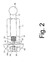
- Fig. 2 is a plan view of chain connecting pin extracting device 10.
- chain connecting pin extracting device 10 comprises a main body 11, a pin extractor support in the form of a force applying unit 12 including a shaft 20 with a male threaded component 31 that screws into a female threaded component 22 formed in main body 11, and a pin extractor 13 connected to the tip of shaft 20.
- a wooden grip 27 is screwed into the longitudinal side of main body 11, and a storage space is formed in grip 27 for storing two connecting pins 29 that are used to replace the connecting pin 53 discussed above after connecting pin 53 is removed from chain 50.
- Main body 11 is a generally hexagonal-shaped cylindrical member with a mounting recess 21 formed therein.
- a support pin 23 is mounted in mounting recess 21 for supporting pin extractor 13, and a plurality of positioning protrusions 24 are disposed in mounting recess 21 for positioning chain 50 during the extraction operation.
- Positioning protrusions 24 are formed in the same shape as the teeth of the sprockets engaged by chain 50 and are oriented such that, when chain 50 is positioned on positioning protrusions 24, connecting pin 53 aligns with pin extractor 13.
- a link support in the form of a positioning bracket 25 with a bushing 26 having a flanged tip 26a is provided for restricting axial movement of the outer links 51 of chain 50 as connecting pin 53 is pushed by pin extractor 13.
- Bushing 26 has a through hole with a diameter large enough to receive connecting pin 53 therein. The top of bushing 26 and the corresponding top part of positioning bracket 25 are open to allow the extracted connecting pin 53 to be removed.
- An extractor attachment component 32 having a smaller diameter than the male threaded component 31 of shaft 20 is formed at the inner tip of shaft 20, and a cylindrical holder 33 for detachably mounting pin extractor 13 is screwed onto extractor attachment component 32.
- An engagement hole 33a for engaging pin extractor 13 is formed in the bottom of holder 33, and a mounting hole 34 for mounting pin extractor 13 is formed in the center of extractor attachment component 32.
- a hand grip 30 is mounted to the outer end of shaft 20 through a mounting shaft 37 that extends through a handle attachment hole 36 formed diametrically through the outer end of shaft 20.
- Hand grip 30 includes two wooden grips 38 with female threaded components that engage male threaded components 37a formed on opposite ends of mounting shaft 37. Rotation of hand grip 30 causes extractor 13 to move in a direction of a pin extractor axis defined by the longitudinal direction of pin extractor 13.
- the pin extractor axis is generally coaxial with a connecting pin axis that is defined by the longitudinal direction of connecting pin 53 when chain 50 is positioned for removal of connecting pin 53.
- a steel ball bearing 35 is mounted in the bottom of mounting hole 34 so that pin extractor 13 is rotatable relative to shaft 20.
- pin extractor 13 rotates relative to connecting pin 53 until the contact force becomes large, and then pin extractor 13 rotates relative to shaft 20 to avoid any drilling effect on connecting pin 53.
- the rotation of pin extractor 13 relative to shaft 20 also allows pin extractor 13 to be firmly positioned on connecting pin 53 during the extraction operation.
- pin extractor 13 comprises a tip 40 and a force receiving component 41 integrally formed with and extending from tip 40.
- Tip 40 is adapted to apply a chain connecting pin extracting force to connecting pin 53 and includes a tapered surface 40a, and force receiving component 41 is adapted to receive the chain connecting pin extracting force from force applying unit 12.
- Tip 40 has a diameter that is smaller than a diameter of connecting pin 53 and an axial length that is shorter than an axial length of connecting pin 53.
- Force receiving component 41 comprises a residue receiving component 42 and a shaft interface component 43. Residue receiving component 42 forms a first portion of force receiving component 41, and it has a diameter smaller than the diameter of tip 40 so as to form a residue removing surface 45 at a junction with tip 40.
- residue removing surface 45 is oriented substantially perpendicular to the extractor and pin axes.
- Shaft interface component 43 comprises a tapered section 43a, an intermediate section 43b that forms a second portion of force receiving component 41, and a shaft connecting component 43c that forms a third portion of force receiving component 41.
- Shaft connecting component 43c is inserted into the mounting hole 34 of shaft 20.
- Intermediate section 43b has a diameter larger than the diameter of residue receiving component 42 and smaller than a diameter of engagement hole 33a of holder 33
- shaft connecting component 43c has a diameter larger than intermediate section 43b to form an abutment 43d at the junction with intermediate section 43b.
- Abutment 43d engages the bottom of holder 33 when holder 33 is screwed onto the extractor attachment component 32 so that pin extractor 13 is retained to shaft 20.
- the shape and dimensions of intermediate section 43b and shaft connecting component 43c of pin extractor 13 are the same as conventional pin extractors.
- a pin extractor constructed according to the teachings herein may be used with conventional pin extracting devices.
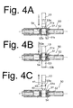
- chain connecting pin extracting device 10 The operation of chain connecting pin extracting device 10 is shown in Figs. 4(A)-4(C).
- hand grip 30 is rotated counterclockwise (when facing hand grip 30) to retract pin extractor 13 sufficiently to allow chain 50 to be positioned in mounting recess 21.
- Chain 50 then is mounted on positioning protrusions 24 so that the connecting pin 53 to be extracted faces pin extractor 13.
- pin extractor 13 advances until the free end of tip 40 contacts connecting pin 53 as shown in Fig. 4(A).
- the flanged tip 26a of bushing 26 simultaneously prevents the corresponding outer link 51 from moving in the pushed direction indicated by the arrow in Fig. 4(A).
- FIGs. 5(A)-5(D) illustrate one possible explanation. Since tapered surface 40a is formed on tip 40, the expanded portion 53a of connecting pin 53 may incline and break off during the extraction operation as shown in Fig. 5(B). After residue 53a breaks off, the ring so formed is stretched in diameter as it moves along tapered surface 40a and onto the constant diameter portion of tip 40 as shown in Fig. 5(C). After residue 53a clears residue removing surface 45 and enters the smaller diameter residue receiving component 42, residue 53a contracts in diameter and therefore contacts residue removing surface 45 as shown in Fig. 5(D) when pin extractor 13 is retracted.
- residue 53a when pin extractor 13 is retracted, residue 53a might be deformed or skewed by the rotation of pin extractor 13, and the skewed residue 53a might be caught by residue removing surface 45 as pin extractor 13 is retracted.
- residue 53a contracts in diameter after is passes residue removing surface 45, even in the absence of tapered surface 40a, so tapered surface 40a is not considered an essential component. Residue 53a then will be caught and easily removed by residue removing surface 45, thus allowing proper installation of the new spare pin 29.
- a spring member 120 for removing residue can be provided in the residue receiving component 42 of a pin extractor 113.
- spring member 120 has a diameter smaller than connecting pin 53 and larger than tip 40.
- a tapered section 43a is formed between residue receiving component 42 and intermediate section 43b of pin extractor 13. This tapered section 43a may be omitted, but providing tapered section 43a allows residue to be caught and removed by tapered section 43a when several residue pieces are left in residue receiving component 42.
Landscapes
- Engineering & Computer Science (AREA)
- Mechanical Engineering (AREA)
- Hand Tools For Fitting Together And Separating, Or Other Hand Tools (AREA)
- Automatic Tool Replacement In Machine Tools (AREA)
- Load-Engaging Elements For Cranes (AREA)
Abstract
Description
- The present invention is directed to link chains and, more particularly, to a chain connecting pin extracting apparatus that may be used to remove a connecting pin that connects the links together.
- Chain connecting pin extractors are tools used when modifying or replacing chains of the type that have alternating first and second link pairs pivotably connected together by a series of connecting pins. As shown in Fig. 4(A), for example, a
narrow chain 50 may comprise pairs ofouter links 51 that alternate with pairs ofinner links 52 in an overlapping manner. A connectingpin 53 extends through aligned openings in theouter links 51 andinner links 52 to pivotably connect them together. Ring-shaped recesses outer links 51, and expandedportions pin 53 are crimped into therespective recesses pin 53 are greater than the diameter of the central portion of connectingpin 53. Aroller 54 surrounding connectingpin 53 is rotatably supported by theinner link 52. Because connectingpin 53 is crimped intorecesses outer links 51, it is less likely to protrude beyond the sides ofouter links 51, thus further reducing the width ofchain 50. - A chain connecting pin extractor typically removes the connecting pin of a closed-loop chain so that the links connected by the connecting pin may be separated to thereby open the loop. A chain connecting pin extractor used to modify or replace a bicycle chain is disclosed at page 205 of Shimano 2003 Bicycle Components, a retail sales manual published by Shimano Inc.
- Conventional chain connecting pin extractors comprise a main body, a pin extractor and a handle component used to operate the pin extractor. The main body has a female threaded component and a link support, wherein the female threaded component is aligned with the connecting pin when the chain is mounted to the main body, and the link support supports the outer link of the chain in the axial direction of the connecting pin. The handle component has a male threaded component that screws into the female threaded component, and the pin extractor is detachably connected to the tip of the male threaded component. A diameter of a tip of the pin extractor is smaller than a diameter of the connecting pin, and a diameter of the portion of the pin extractor that connects to the male threaded component is larger than the diameter of the tip.
- To use the chain connecting pin extractor, the chain is mounted to the main body such that the connecting pin that is to be removed faces the pin extractor. Turning the handle component causes the pin extractor to press against and move the connecting pin while the chain is prevented from moving by the link support. The links may be disconnected when the connecting pin is removed from at least the outer link that faces the handle component.
- In the bicycle field, a chain may be used with sprocket clusters having as many as ten sprockets, wherein a derailleur is used to switch the chain among the individual sprockets. Because the sprocket cluster must fit in the limited axial space between the bicycle frame components that straddle the rear wheel, a larger number of sprockets results in narrower gaps between the sprockets, so the chain also must be thinner. A chain such as the one described above, wherein the connecting pin does not protrude axially outward from the outer links, may be used for this purpose
- When the links of such narrow chains are disconnected using a conventional chain connecting pin extractor, the expanded portion of the connecting pin that faces the pin extractor sometimes breaks off from the remainder of the connecting pin, thus leaving a ring-shaped residue in the ring-shaped recess in the outer link. This residue makes it difficult if not impossible to insert a replacement pin, so the residue must be removed using a different tool.
- The present invention is directed to various features of a chain connecting pin extracting apparatus. In one embodiment, a chain connecting pin extracting apparatus is provided for extracting a connecting pin that couples a first link to a second link through a pin opening disposed in the first link. The apparatus comprises a main body; an extractor support supported by the main body; and an extractor supported by the extractor support for movement in a direction of a pin extractor axis defined by the pin extractor. The pin extractor comprises a force receiving component adapted to receive a connecting pin extracting force; a tip adapted to apply the connecting pin extracting force to the connecting pin, wherein the tip is dimensioned to extend into the pin opening in a first direction along the pin extractor axis; and a residue moving surface disposed between the force receiving component and the tip and facing at least in part in a second direction opposite the first direction so that, after the tip extends in the first direction into the pin opening, movement of the pin extractor in the second direction causes the residue moving surface to move residue of the connecting pin disposed at the first link that was caused by movement of the tip in the first direction. A link support may be spaced apart from the extractor support in a direction of the pin extractor axis so that at least one of the first link and the second link is supported by the link support when the extractor moves in the first direction.
- Additional inventive features will become apparent from the description below, and such features alone or in combination with the above features may form the basis of further inventions as recited in the claims and their equivalents.
-
- Fig. 1 is a cross sectional view of a particular embodiment of a chain connecting pin extracting apparatus in the form of a complete chain connecting pin extracting device;
- Fig. 2 is a plan view of the chain connecting pin extracting device;
- Fig. 3 is a view of a chain connecting pin extracting apparatus in the form of a chain connecting pin extractor;
- Figs. 4(A)-4(C) are views illustrating a chain connecting pin extracting operation;
- Figs. 5(A)-5(C) are views illustrating how chain connecting pin residue is formed during the chain connecting pin extracting operation; and
- Figs. 6(A)-6(C) are views illustrating the operation of another embodiment of a chain connecting pin extracting apparatus.
-
- Fig. 1 is a cross sectional view of a particular embodiment of a chain connecting pin extracting apparatus in the form of a complete chain connecting
pin extracting device 10, and Fig. 2 is a plan view of chain connectingpin extracting device 10. In this embodiment, chain connectingpin extracting device 10 comprises amain body 11, a pin extractor support in the form of aforce applying unit 12 including ashaft 20 with a male threadedcomponent 31 that screws into a female threadedcomponent 22 formed inmain body 11, and apin extractor 13 connected to the tip ofshaft 20. Awooden grip 27 is screwed into the longitudinal side ofmain body 11, and a storage space is formed ingrip 27 for storing two connectingpins 29 that are used to replace the connectingpin 53 discussed above after connectingpin 53 is removed fromchain 50. -
Main body 11 is a generally hexagonal-shaped cylindrical member with amounting recess 21 formed therein. Asupport pin 23 is mounted inmounting recess 21 for supportingpin extractor 13, and a plurality ofpositioning protrusions 24 are disposed inmounting recess 21 forpositioning chain 50 during the extraction operation. Positioningprotrusions 24 are formed in the same shape as the teeth of the sprockets engaged bychain 50 and are oriented such that, whenchain 50 is positioned onpositioning protrusions 24, connectingpin 53 aligns withpin extractor 13. A link support in the form of apositioning bracket 25 with a bushing 26 having a flangedtip 26a is provided for restricting axial movement of theouter links 51 ofchain 50 as connectingpin 53 is pushed bypin extractor 13. Bushing 26 has a through hole with a diameter large enough to receive connectingpin 53 therein. The top of bushing 26 and the corresponding top part ofpositioning bracket 25 are open to allow the extracted connectingpin 53 to be removed. - An
extractor attachment component 32 having a smaller diameter than the male threadedcomponent 31 ofshaft 20 is formed at the inner tip ofshaft 20, and acylindrical holder 33 for detachablymounting pin extractor 13 is screwed ontoextractor attachment component 32. Anengagement hole 33a forengaging pin extractor 13 is formed in the bottom ofholder 33, and amounting hole 34 for mountingpin extractor 13 is formed in the center ofextractor attachment component 32. - A
hand grip 30 is mounted to the outer end ofshaft 20 through amounting shaft 37 that extends through ahandle attachment hole 36 formed diametrically through the outer end ofshaft 20.Hand grip 30 includes twowooden grips 38 with female threaded components that engage male threadedcomponents 37a formed on opposite ends ofmounting shaft 37. Rotation ofhand grip 30 causesextractor 13 to move in a direction of a pin extractor axis defined by the longitudinal direction ofpin extractor 13. The pin extractor axis is generally coaxial with a connecting pin axis that is defined by the longitudinal direction of connectingpin 53 whenchain 50 is positioned for removal of connectingpin 53. - A steel ball bearing 35 is mounted in the bottom of
mounting hole 34 so thatpin extractor 13 is rotatable relative toshaft 20. Thus, when the tip ofpin extractor 13contacts connecting pin 53 andhand grip 30 is rotated,pin extractor 13 rotates relative to connectingpin 53 until the contact force becomes large, and thenpin extractor 13 rotates relative toshaft 20 to avoid any drilling effect on connectingpin 53. The rotation ofpin extractor 13 relative toshaft 20 also allowspin extractor 13 to be firmly positioned on connectingpin 53 during the extraction operation. - As shown in Fig. 3,
pin extractor 13 comprises atip 40 and aforce receiving component 41 integrally formed with and extending fromtip 40.Tip 40 is adapted to apply a chain connecting pin extracting force to connectingpin 53 and includes atapered surface 40a, andforce receiving component 41 is adapted to receive the chain connecting pin extracting force fromforce applying unit 12.Tip 40 has a diameter that is smaller than a diameter of connectingpin 53 and an axial length that is shorter than an axial length of connectingpin 53.Force receiving component 41 comprises aresidue receiving component 42 and ashaft interface component 43.Residue receiving component 42 forms a first portion offorce receiving component 41, and it has a diameter smaller than the diameter oftip 40 so as to form aresidue removing surface 45 at a junction withtip 40. In this embodiment,residue removing surface 45 is oriented substantially perpendicular to the extractor and pin axes. -
Shaft interface component 43 comprises atapered section 43a, anintermediate section 43b that forms a second portion offorce receiving component 41, and ashaft connecting component 43c that forms a third portion offorce receiving component 41.Shaft connecting component 43c is inserted into themounting hole 34 ofshaft 20.Intermediate section 43b has a diameter larger than the diameter of residue receivingcomponent 42 and smaller than a diameter ofengagement hole 33a ofholder 33, andshaft connecting component 43c has a diameter larger thanintermediate section 43b to form anabutment 43d at the junction withintermediate section 43b.Abutment 43d engages the bottom ofholder 33 whenholder 33 is screwed onto theextractor attachment component 32 so thatpin extractor 13 is retained toshaft 20. The shape and dimensions ofintermediate section 43b andshaft connecting component 43c ofpin extractor 13 are the same as conventional pin extractors. Thus, a pin extractor constructed according to the teachings herein may be used with conventional pin extracting devices. - The operation of chain connecting
pin extracting device 10 is shown in Figs. 4(A)-4(C). Initially,hand grip 30 is rotated counterclockwise (when facing hand grip 30) to retractpin extractor 13 sufficiently to allowchain 50 to be positioned in mountingrecess 21.Chain 50 then is mounted on positioningprotrusions 24 so that the connectingpin 53 to be extracted facespin extractor 13. Whenhand grip 30 is rotated clockwise,pin extractor 13 advances until the free end oftip 40contacts connecting pin 53 as shown in Fig. 4(A). Theflanged tip 26a ofbushing 26 simultaneously prevents the correspondingouter link 51 from moving in the pushed direction indicated by the arrow in Fig. 4(A). - Further rotation of
hand grip 30 causespin extractor 13 to push connectingpin 53 out of the opposite side ofchain 50 as shown in Fig. 4(B). At this time, the expandedportion 53a of connectingpin 53 adjacent to tip 40 (now termed theresidue 53a) may remain in thecorresponding recess 51a. Ifresidue 53a is left in that position, it will obstruct the positioning of the newspare pin 29 and prevent thespare pin 29 from being mounted properly. However, as shown in Figure 4(C), whenhand grip 30 is rotated in the counterclockwise direction to retractpin extractor 13 after connectingpin 53 has been removed,residue 53a is caught byresidue removing surface 45, thus allowingresidue 53a to be removed fromrecess 51a. - It is not entirely clear why
residue 53a is caught byresidue removing surface 45 whenpin extractor 13 is retracted. Figs. 5(A)-5(D) illustrate one possible explanation. Since taperedsurface 40a is formed ontip 40, the expandedportion 53a of connectingpin 53 may incline and break off during the extraction operation as shown in Fig. 5(B). Afterresidue 53a breaks off, the ring so formed is stretched in diameter as it moves along taperedsurface 40a and onto the constant diameter portion oftip 40 as shown in Fig. 5(C). Afterresidue 53a clearsresidue removing surface 45 and enters the smaller diameterresidue receiving component 42,residue 53a contracts in diameter and therefore contactsresidue removing surface 45 as shown in Fig. 5(D) whenpin extractor 13 is retracted. - Another possible explanation is that, when
pin extractor 13 is retracted,residue 53a might be deformed or skewed by the rotation ofpin extractor 13, and the skewedresidue 53a might be caught byresidue removing surface 45 aspin extractor 13 is retracted. In any event, it is assumed thatresidue 53a contracts in diameter after is passesresidue removing surface 45, even in the absence of taperedsurface 40a, sotapered surface 40a is not considered an essential component.Residue 53a then will be caught and easily removed byresidue removing surface 45, thus allowing proper installation of the newspare pin 29. - While the above is a description of various embodiments of inventive features, further modifications may be employed without departing from the spirit and scope of the present invention. For example, while a chain connecting pin extracting device capable of mass production was described, many other configurations are possible. For example, as shown in Figs. 6(A)-6(D), a
spring member 120 for removing residue can be provided in theresidue receiving component 42 of apin extractor 113. In this embodiment,spring member 120 has a diameter smaller than connectingpin 53 and larger thantip 40. - Operation of this embodiment is substantially the same as the first embodiment. However, when
residue 53a passesresidue removing surface 45,residue 53acontracts spring member 120 diametrically as shown in Fig. 6(B) so thatspring member 120 passes through the central opening ofresidue 53a.Spring member 120 subsequently expands after it passes byresidue 53a as shown in Fig. 6(C). Thereafter,spring member 120 removesresidue 53a fromrecess 51 a whenpin extractor 113 is retracted as shown in Fig. 6(D). If for somereason spring member 120 does not catchresidue 53a, thenresidue 53a will be caught and removed byresidue removing surface 45 ofextractor pin 113. - In the described embodiments, a
tapered section 43a is formed betweenresidue receiving component 42 andintermediate section 43b ofpin extractor 13. Thistapered section 43a may be omitted, but providingtapered section 43a allows residue to be caught and removed by taperedsection 43a when several residue pieces are left inresidue receiving component 42. - The size, shape, location or orientation of the various components may be changed as desired. Components that are shown directly connected or contacting each other may have intermediate structures disposed between them. The functions of one element may be performed by two, and vice versa. The structures and functions of one embodiment may be adopted in another embodiment. It is not necessary for all advantages to be present in a particular embodiment at the same time. Every feature which is unique from the prior art, alone or in combination with other features, also should be considered a separate description of further inventions by the applicant, including the structural and/or functional concepts embodied by such feature(s). Thus, the scope of the invention should not be limited by the specific structures disclosed or the apparent initial focus or emphasis on a particular structure or feature.
Claims (15)
- A chain connecting pin extracting apparatus (10) for extracting a connecting pin (53) that couples a first link (51) to a second link (52) through a pin opening disposed in the first link (51), wherein the apparatus (10) comprises:a main body (11);a pin extractor support (12) supported by the main body (11);a pin extractor (13) supported by the pin extractor support (12) for movement in a direction of a pin extractor axis defined by the pin extractor (13), wherein the pin extractor (13) comprises:a force receiving component (41) adapted to receive a connecting pin extracting force;a tip (40) adapted to apply the connecting pin extracting force to the connecting pin (53), wherein the tip (40) is dimensioned to extend into the pin opening in a first direction along the pin extractor axis; anda residue moving surface disposed between the force receiving component (41) and the tip (40) and facing at least in part in a second direction opposite the first direction so that, after the tip (40) extends in the first direction into the pin opening, movement of the pin extractor (13) in the second direction causes the residue moving surface to move residue of the connecting pin (53) disposed at the first link (51) that was caused by movement of the tip (40) in the first direction; anda link support (25) spaced apart from the pin extractor support (12) in a direction of the pin extractor axis so that at least one of the first link (51) and the second link (52) is supported by the link support (25) when the pin extractor (13) moves in the first direction.
- The apparatus (10) according to claim 1 wherein the main body (11) comprises a female threaded component (22).
- The apparatus (10) according to claim 2 wherein the pin extractor support (12) further comprises a force applying unit having a male threaded component (31) that engages the female threaded component (22), and wherein the force applying unit supports the pin extractor (13) so that rotation of the force applying unit moves the pin extractor (13) in the first and second directions.
- The apparatus (10) according to claim 3 wherein the force applying unit (12) further comprises a handle having an elongated portion that extends at least partially in a direction perpendicular to the pin extractor axis.
- The apparatus (10) according to claim 3 or 4 wherein the pin extractor support (12) comprises a holder that detachably couples the pin extractor (13) to the pin extractor support (12).
- The apparatus (10) according to claim 5 wherein the pin extractor (13) is coupled to the force applying unit (12) through a bearing so that the force applying unit (12) is rotatable relative to the pin extractor (13).
- The apparatus (10) according to any of the preceding claims wherein the force receiving component (41) has a first portion (42) extending from the tip (40), and wherein the first portion (42) has a diameter smaller than a diameter of the tip (40) at a junction of the first portion (42) and the tip (40) so as to form the residue moving surface.
- The apparatus (10) according to claim 7 wherein the residue moving surface is oriented substantially perpendicular to the pin extractor axis.
- The apparatus (10) according to claim 7 or 8 wherein a free end of the tip (40) forms a tapered surface (40a).
- The apparatus (10) according to any of claims 7 to 9 wherein the force receiving component (41) has a second portion (42) extending from the first portion (42), and wherein the second portion (43b) has a diameter larger than the diameter of the first portion (42).
- The apparatus (10) according to claim 10 wherein a junction of the first portion (42) and the second portion (43b) forms a tapered section.
- The apparatus (10) according to claim 10 or 11 wherein the force receiving component (41) has a third portion (43c) extending from the second portion (43b), wherein the third portion (43c) is supported by the pin extractor support (12).
- The apparatus (10) according to claim 12 wherein the diameter of the second portion (43b) is smaller than a diameter of the third portion (43c).
- A pin extractor (13) for a connecting pin extracting apparatus (10) that extracts a connecting pin (53) that couples a first link (51) to a second link (52) through a pin opening disposed in the first link (51), wherein the connecting pin extracting apparatus (10) is of the type comprising a main body (11), a pin extractor support (12) supported by the main body (11) for supporting the pin extractor (13) along a pin extractor axis, and a link support spaced apart from the pin extractor support (12) in a direction of the pin extractor axis, and wherein the pin extractor support (12) moves along the pin extractor axis to apply a connecting pin extracting force to the connecting pin while at least one of the first and second links (51, 52) is supported by the link support (25), wherein the pin extractor (13) comprises:a force receiving component (41) adapted to receive the connecting pin extracting force;a tip (40) adapted to apply the connecting pin extracting force to the connecting pin, wherein the tip (40) is dimensioned to extend into the pin opening in a first direction along the pin extractor axis; anda residue moving surface disposed between the force receiving component (41) and the tip (40) and facing at least in part in a second direction opposite the first direction so that, after the tip (40) extends in the first direction into the pin opening, movement of the pin extractor (13) in the second direction causes the residue moving surface to move residue of the connecting pin disposed at the first link (51) that was caused by movement of the tip (40) in the first direction.
- The pin extractor according to claim 14 for a connecting pin extracting apparatus according to any of claim 7 to 13.
Applications Claiming Priority (2)
| Application Number | Priority Date | Filing Date | Title |
|---|---|---|---|
| JP2003148926A JP3680066B2 (en) | 2003-05-27 | 2003-05-27 | Chain cutting tool and shaft removal pin used therefor |
| JP2003148926 | 2003-05-27 |
Publications (2)
| Publication Number | Publication Date |
|---|---|
| EP1481767A1 true EP1481767A1 (en) | 2004-12-01 |
| EP1481767B1 EP1481767B1 (en) | 2008-07-23 |
Family
ID=33128211
Family Applications (1)
| Application Number | Title | Priority Date | Filing Date |
|---|---|---|---|
| EP04012504A Expired - Lifetime EP1481767B1 (en) | 2003-05-27 | 2004-05-26 | Tool for extracting chain pins |
Country Status (7)
| Country | Link |
|---|---|
| US (1) | US7082747B2 (en) |
| EP (1) | EP1481767B1 (en) |
| JP (1) | JP3680066B2 (en) |
| CN (1) | CN1275718C (en) |
| AT (1) | ATE401993T1 (en) |
| DE (1) | DE602004015195D1 (en) |
| TW (1) | TW200426001A (en) |
Cited By (1)
| Publication number | Priority date | Publication date | Assignee | Title |
|---|---|---|---|---|
| CN107855980A (en) * | 2017-10-10 | 2018-03-30 | 中国空气动力研究与发展中心高速空气动力研究所 | One kind is pulled pin and take-up device |
Families Citing this family (12)
| Publication number | Priority date | Publication date | Assignee | Title |
|---|---|---|---|---|
| US7562430B2 (en) * | 2005-01-10 | 2009-07-21 | Mhe Technologies, Inc. | Pin changing device and method |
| USD543818S1 (en) * | 2005-06-13 | 2007-06-05 | Shimano Inc. | Chain cutter |
| US7216472B1 (en) * | 2006-05-09 | 2007-05-15 | Wen-Pin Wang | Guiding shaft structure for chain connector |
| US7409817B1 (en) * | 2007-10-07 | 2008-08-12 | Hung-Chen Huang | Bicycle chain splitter |
| US7430849B1 (en) | 2008-05-16 | 2008-10-07 | Practical Inventions, Llc | Conveyor chain pin remover |
| CN101559586B (en) * | 2009-05-15 | 2010-10-13 | 苏州江南嘉捷电梯股份有限公司 | Disassembling tool of link sheet component of step chain of automatic escalator |
| US8166745B2 (en) * | 2009-06-05 | 2012-05-01 | Starwinn Cycle Corporation | Tool for extracting and inserting pins of roller chains |
| TW201313362A (en) * | 2011-09-20 | 2013-04-01 | Diro Tech Corp | Chain riveter with position adjusting |
| CN104626054A (en) * | 2015-01-19 | 2015-05-20 | 浙江巨人控股有限公司 | Quick chain cutting tool |
| TWI682835B (en) | 2019-04-23 | 2020-01-21 | 極點股份有限公司 | Chain tool |
| US11714501B2 (en) * | 2019-07-25 | 2023-08-01 | Hewlett-Packard Development Company, L.P. | Digital pen holder |
| TWI873057B (en) * | 2024-07-01 | 2025-02-11 | 極點股份有限公司 | Chain tool |
Citations (5)
| Publication number | Priority date | Publication date | Assignee | Title |
|---|---|---|---|---|
| US3576064A (en) * | 1968-09-26 | 1971-04-27 | Mc Donnell Douglas Corp | Rivet removing tool and method |
| US4365401A (en) * | 1980-10-20 | 1982-12-28 | Owatonna Tool Company | Rivet removal and fastening tool |
| US4602414A (en) * | 1985-02-14 | 1986-07-29 | Center Industries Corporation | Rivet tool having reversible anvil |
| DE9217590U1 (en) * | 1992-12-23 | 1993-02-25 | Ing. Heinz Schmoll KG, 6242 Kronberg | Rivet remover for hollow rivets |
| US20030084555A1 (en) * | 2001-11-07 | 2003-05-08 | Campagnolo Srl | Tool for inserting and extracting pins of roller chains |
Family Cites Families (5)
| Publication number | Priority date | Publication date | Assignee | Title |
|---|---|---|---|---|
| US1469594A (en) * | 1920-07-09 | 1923-10-02 | Harley Davidson Motor Co Inc | Rivet remover |
| US2826893A (en) * | 1955-04-26 | 1958-03-18 | A M Collot Supplies Inc | Chain pin extractor with a plurality of hinged stops |
| US4635437A (en) * | 1984-07-12 | 1987-01-13 | R. W. Steele, II | Chain punch |
| US5140736A (en) * | 1992-03-04 | 1992-08-25 | Hsiao K H | Bicycle chain rivet dismantling apparatus |
| US5251341A (en) * | 1993-03-18 | 1993-10-12 | Seals Robert L | Bicycle tool |
-
2003
- 2003-05-27 JP JP2003148926A patent/JP3680066B2/en not_active Expired - Fee Related
-
2004
- 2004-02-04 TW TW093102534D patent/TW200426001A/en unknown
- 2004-05-25 US US10/853,963 patent/US7082747B2/en not_active Expired - Fee Related
- 2004-05-26 AT AT04012504T patent/ATE401993T1/en not_active IP Right Cessation
- 2004-05-26 EP EP04012504A patent/EP1481767B1/en not_active Expired - Lifetime
- 2004-05-26 DE DE602004015195T patent/DE602004015195D1/en not_active Expired - Fee Related
- 2004-05-27 CN CN200410047661.6A patent/CN1275718C/en not_active Expired - Fee Related
Patent Citations (5)
| Publication number | Priority date | Publication date | Assignee | Title |
|---|---|---|---|---|
| US3576064A (en) * | 1968-09-26 | 1971-04-27 | Mc Donnell Douglas Corp | Rivet removing tool and method |
| US4365401A (en) * | 1980-10-20 | 1982-12-28 | Owatonna Tool Company | Rivet removal and fastening tool |
| US4602414A (en) * | 1985-02-14 | 1986-07-29 | Center Industries Corporation | Rivet tool having reversible anvil |
| DE9217590U1 (en) * | 1992-12-23 | 1993-02-25 | Ing. Heinz Schmoll KG, 6242 Kronberg | Rivet remover for hollow rivets |
| US20030084555A1 (en) * | 2001-11-07 | 2003-05-08 | Campagnolo Srl | Tool for inserting and extracting pins of roller chains |
Cited By (2)
| Publication number | Priority date | Publication date | Assignee | Title |
|---|---|---|---|---|
| CN107855980A (en) * | 2017-10-10 | 2018-03-30 | 中国空气动力研究与发展中心高速空气动力研究所 | One kind is pulled pin and take-up device |
| CN107855980B (en) * | 2017-10-10 | 2023-10-20 | 中国空气动力研究与发展中心高速空气动力研究所 | Pin pulling and tensioning device |
Also Published As
| Publication number | Publication date |
|---|---|
| CN1572428A (en) | 2005-02-02 |
| ATE401993T1 (en) | 2008-08-15 |
| US7082747B2 (en) | 2006-08-01 |
| DE602004015195D1 (en) | 2008-09-04 |
| JP3680066B2 (en) | 2005-08-10 |
| JP2004351526A (en) | 2004-12-16 |
| TW200426001A (en) | 2004-12-01 |
| EP1481767B1 (en) | 2008-07-23 |
| CN1275718C (en) | 2006-09-20 |
| US20040261392A1 (en) | 2004-12-30 |
Similar Documents
| Publication | Publication Date | Title |
|---|---|---|
| US7082747B2 (en) | Chain connecting pin extracting apparatus | |
| US7473198B2 (en) | Apparatus for connecting bicycle chain links together | |
| US6748637B2 (en) | Tool for inserting and extracting pins of roller chains | |
| DE102009005199B4 (en) | Fahrradhinterderailleur | |
| US8166745B2 (en) | Tool for extracting and inserting pins of roller chains | |
| JP3203080U (en) | Welding torch maintenance tool | |
| US7204173B2 (en) | Rotatable die tong jaw | |
| TW201343339A (en) | Chain tool | |
| JP4803188B2 (en) | Differential assembly method and assembly apparatus | |
| US20050087042A1 (en) | Sleeve assembly for turning bolts or nuts of different sizes and/or having different heads | |
| CN1397746A (en) | Device and method for inserting a coupling pin into a chain, especially a bicycle chain | |
| KR101179197B1 (en) | Supporter for gear separate | |
| JP2007021633A (en) | Gear puller | |
| US20240336320A1 (en) | Chainring and tool for electric bicycle | |
| TWM517033U (en) | Chain disassembling tool | |
| JP4859510B2 (en) | Collet chuck | |
| JP4594009B2 (en) | Chuck device | |
| KR200390312Y1 (en) | A wrench adjustable handle | |
| US20110036688A1 (en) | Conveyor having a grip unit | |
| JP2011200908A (en) | Welding torch | |
| KR101006572B1 (en) | Wheel nut wrench | |
| JP2006326747A (en) | Chuck device, child claw replacement jig, child claw attachment method and child claw removal method | |
| JP3622802B2 (en) | Spring pin removal tool | |
| JPH0859164A (en) | Tread fixing device of man conveyor | |
| JPH07285005A (en) | Chuck device |
Legal Events
| Date | Code | Title | Description |
|---|---|---|---|
| PUAI | Public reference made under article 153(3) epc to a published international application that has entered the european phase |
Free format text: ORIGINAL CODE: 0009012 |
|
| AK | Designated contracting states |
Kind code of ref document: A1 Designated state(s): AT BE BG CH CY CZ DE DK EE ES FI FR GB GR HU IE IT LI LU MC NL PL PT RO SE SI SK TR |
|
| AX | Request for extension of the european patent |
Extension state: AL HR LT LV MK |
|
| 17P | Request for examination filed |
Effective date: 20041221 |
|
| AKX | Designation fees paid |
Designated state(s): AT BE BG CH CY CZ DE DK EE ES FI FR GB GR HU IE IT LI LU MC NL PL PT RO SE SI SK TR |
|
| RAP1 | Party data changed (applicant data changed or rights of an application transferred) |
Owner name: SHIMANO INC. |
|
| 17Q | First examination report despatched |
Effective date: 20060112 |
|
| GRAP | Despatch of communication of intention to grant a patent |
Free format text: ORIGINAL CODE: EPIDOSNIGR1 |
|
| GRAS | Grant fee paid |
Free format text: ORIGINAL CODE: EPIDOSNIGR3 |
|
| GRAA | (expected) grant |
Free format text: ORIGINAL CODE: 0009210 |
|
| AK | Designated contracting states |
Kind code of ref document: B1 Designated state(s): AT BE BG CH CY CZ DE DK EE ES FI FR GB GR HU IE IT LI LU MC NL PL PT RO SE SI SK TR |
|
| REG | Reference to a national code |
Ref country code: GB Ref legal event code: FG4D |
|
| REG | Reference to a national code |
Ref country code: CH Ref legal event code: EP |
|
| REG | Reference to a national code |
Ref country code: IE Ref legal event code: FG4D |
|
| REF | Corresponds to: |
Ref document number: 602004015195 Country of ref document: DE Date of ref document: 20080904 Kind code of ref document: P |
|
| NLV1 | Nl: lapsed or annulled due to failure to fulfill the requirements of art. 29p and 29m of the patents act | ||
| PG25 | Lapsed in a contracting state [announced via postgrant information from national office to epo] |
Ref country code: ES Free format text: LAPSE BECAUSE OF FAILURE TO SUBMIT A TRANSLATION OF THE DESCRIPTION OR TO PAY THE FEE WITHIN THE PRESCRIBED TIME-LIMIT Effective date: 20081103 Ref country code: NL Free format text: LAPSE BECAUSE OF FAILURE TO SUBMIT A TRANSLATION OF THE DESCRIPTION OR TO PAY THE FEE WITHIN THE PRESCRIBED TIME-LIMIT Effective date: 20080723 Ref country code: PT Free format text: LAPSE BECAUSE OF FAILURE TO SUBMIT A TRANSLATION OF THE DESCRIPTION OR TO PAY THE FEE WITHIN THE PRESCRIBED TIME-LIMIT Effective date: 20081223 |
|
| PG25 | Lapsed in a contracting state [announced via postgrant information from national office to epo] |
Ref country code: FI Free format text: LAPSE BECAUSE OF FAILURE TO SUBMIT A TRANSLATION OF THE DESCRIPTION OR TO PAY THE FEE WITHIN THE PRESCRIBED TIME-LIMIT Effective date: 20080723 Ref country code: AT Free format text: LAPSE BECAUSE OF FAILURE TO SUBMIT A TRANSLATION OF THE DESCRIPTION OR TO PAY THE FEE WITHIN THE PRESCRIBED TIME-LIMIT Effective date: 20080723 Ref country code: BG Free format text: LAPSE BECAUSE OF FAILURE TO SUBMIT A TRANSLATION OF THE DESCRIPTION OR TO PAY THE FEE WITHIN THE PRESCRIBED TIME-LIMIT Effective date: 20081023 Ref country code: SI Free format text: LAPSE BECAUSE OF FAILURE TO SUBMIT A TRANSLATION OF THE DESCRIPTION OR TO PAY THE FEE WITHIN THE PRESCRIBED TIME-LIMIT Effective date: 20080723 |
|
| PG25 | Lapsed in a contracting state [announced via postgrant information from national office to epo] |
Ref country code: BE Free format text: LAPSE BECAUSE OF FAILURE TO SUBMIT A TRANSLATION OF THE DESCRIPTION OR TO PAY THE FEE WITHIN THE PRESCRIBED TIME-LIMIT Effective date: 20080723 |
|
| PG25 | Lapsed in a contracting state [announced via postgrant information from national office to epo] |
Ref country code: EE Free format text: LAPSE BECAUSE OF FAILURE TO SUBMIT A TRANSLATION OF THE DESCRIPTION OR TO PAY THE FEE WITHIN THE PRESCRIBED TIME-LIMIT Effective date: 20080723 Ref country code: DK Free format text: LAPSE BECAUSE OF FAILURE TO SUBMIT A TRANSLATION OF THE DESCRIPTION OR TO PAY THE FEE WITHIN THE PRESCRIBED TIME-LIMIT Effective date: 20080723 |
|
| PG25 | Lapsed in a contracting state [announced via postgrant information from national office to epo] |
Ref country code: RO Free format text: LAPSE BECAUSE OF FAILURE TO SUBMIT A TRANSLATION OF THE DESCRIPTION OR TO PAY THE FEE WITHIN THE PRESCRIBED TIME-LIMIT Effective date: 20080723 Ref country code: SK Free format text: LAPSE BECAUSE OF FAILURE TO SUBMIT A TRANSLATION OF THE DESCRIPTION OR TO PAY THE FEE WITHIN THE PRESCRIBED TIME-LIMIT Effective date: 20080723 Ref country code: CZ Free format text: LAPSE BECAUSE OF FAILURE TO SUBMIT A TRANSLATION OF THE DESCRIPTION OR TO PAY THE FEE WITHIN THE PRESCRIBED TIME-LIMIT Effective date: 20080723 |
|
| PLBE | No opposition filed within time limit |
Free format text: ORIGINAL CODE: 0009261 |
|
| STAA | Information on the status of an ep patent application or granted ep patent |
Free format text: STATUS: NO OPPOSITION FILED WITHIN TIME LIMIT |
|
| 26N | No opposition filed |
Effective date: 20090424 |
|
| PG25 | Lapsed in a contracting state [announced via postgrant information from national office to epo] |
Ref country code: IT Free format text: LAPSE BECAUSE OF FAILURE TO SUBMIT A TRANSLATION OF THE DESCRIPTION OR TO PAY THE FEE WITHIN THE PRESCRIBED TIME-LIMIT Effective date: 20080723 |
|
| PGFP | Annual fee paid to national office [announced via postgrant information from national office to epo] |
Ref country code: DE Payment date: 20090526 Year of fee payment: 6 |
|
| PG25 | Lapsed in a contracting state [announced via postgrant information from national office to epo] |
Ref country code: MC Free format text: LAPSE BECAUSE OF NON-PAYMENT OF DUE FEES Effective date: 20090531 |
|
| REG | Reference to a national code |
Ref country code: CH Ref legal event code: PL |
|
| GBPC | Gb: european patent ceased through non-payment of renewal fee |
Effective date: 20090526 |
|
| PG25 | Lapsed in a contracting state [announced via postgrant information from national office to epo] |
Ref country code: LI Free format text: LAPSE BECAUSE OF NON-PAYMENT OF DUE FEES Effective date: 20090531 Ref country code: CH Free format text: LAPSE BECAUSE OF NON-PAYMENT OF DUE FEES Effective date: 20090531 Ref country code: SE Free format text: LAPSE BECAUSE OF FAILURE TO SUBMIT A TRANSLATION OF THE DESCRIPTION OR TO PAY THE FEE WITHIN THE PRESCRIBED TIME-LIMIT Effective date: 20081023 |
|
| REG | Reference to a national code |
Ref country code: FR Ref legal event code: ST Effective date: 20100129 |
|
| REG | Reference to a national code |
Ref country code: IE Ref legal event code: MM4A |
|
| PG25 | Lapsed in a contracting state [announced via postgrant information from national office to epo] |
Ref country code: IE Free format text: LAPSE BECAUSE OF NON-PAYMENT OF DUE FEES Effective date: 20090526 Ref country code: FR Free format text: LAPSE BECAUSE OF NON-PAYMENT OF DUE FEES Effective date: 20090602 |
|
| PG25 | Lapsed in a contracting state [announced via postgrant information from national office to epo] |
Ref country code: GB Free format text: LAPSE BECAUSE OF NON-PAYMENT OF DUE FEES Effective date: 20090526 Ref country code: PL Free format text: LAPSE BECAUSE OF FAILURE TO SUBMIT A TRANSLATION OF THE DESCRIPTION OR TO PAY THE FEE WITHIN THE PRESCRIBED TIME-LIMIT Effective date: 20080723 |
|
| PG25 | Lapsed in a contracting state [announced via postgrant information from national office to epo] |
Ref country code: GR Free format text: LAPSE BECAUSE OF FAILURE TO SUBMIT A TRANSLATION OF THE DESCRIPTION OR TO PAY THE FEE WITHIN THE PRESCRIBED TIME-LIMIT Effective date: 20081024 |
|
| PG25 | Lapsed in a contracting state [announced via postgrant information from national office to epo] |
Ref country code: DE Free format text: LAPSE BECAUSE OF NON-PAYMENT OF DUE FEES Effective date: 20101201 Ref country code: LU Free format text: LAPSE BECAUSE OF NON-PAYMENT OF DUE FEES Effective date: 20090526 |
|
| PG25 | Lapsed in a contracting state [announced via postgrant information from national office to epo] |
Ref country code: HU Free format text: LAPSE BECAUSE OF FAILURE TO SUBMIT A TRANSLATION OF THE DESCRIPTION OR TO PAY THE FEE WITHIN THE PRESCRIBED TIME-LIMIT Effective date: 20090124 |
|
| PG25 | Lapsed in a contracting state [announced via postgrant information from national office to epo] |
Ref country code: TR Free format text: LAPSE BECAUSE OF FAILURE TO SUBMIT A TRANSLATION OF THE DESCRIPTION OR TO PAY THE FEE WITHIN THE PRESCRIBED TIME-LIMIT Effective date: 20080723 |
|
| PG25 | Lapsed in a contracting state [announced via postgrant information from national office to epo] |
Ref country code: CY Free format text: LAPSE BECAUSE OF FAILURE TO SUBMIT A TRANSLATION OF THE DESCRIPTION OR TO PAY THE FEE WITHIN THE PRESCRIBED TIME-LIMIT Effective date: 20080723 |