EP1481757A1 - Dual wedge fixture locator - Google Patents
Dual wedge fixture locator Download PDFInfo
- Publication number
- EP1481757A1 EP1481757A1 EP20040253201 EP04253201A EP1481757A1 EP 1481757 A1 EP1481757 A1 EP 1481757A1 EP 20040253201 EP20040253201 EP 20040253201 EP 04253201 A EP04253201 A EP 04253201A EP 1481757 A1 EP1481757 A1 EP 1481757A1
- Authority
- EP
- European Patent Office
- Prior art keywords
- wedge
- base
- fixture
- mount
- centerline
- Prior art date
- Legal status (The legal status is an assumption and is not a legal conclusion. Google has not performed a legal analysis and makes no representation as to the accuracy of the status listed.)
- Granted
Links
Images
Classifications
-
- B—PERFORMING OPERATIONS; TRANSPORTING
- B23—MACHINE TOOLS; METAL-WORKING NOT OTHERWISE PROVIDED FOR
- B23Q—DETAILS, COMPONENTS, OR ACCESSORIES FOR MACHINE TOOLS, e.g. ARRANGEMENTS FOR COPYING OR CONTROLLING; MACHINE TOOLS IN GENERAL CHARACTERISED BY THE CONSTRUCTION OF PARTICULAR DETAILS OR COMPONENTS; COMBINATIONS OR ASSOCIATIONS OF METAL-WORKING MACHINES, NOT DIRECTED TO A PARTICULAR RESULT
- B23Q1/00—Members which are comprised in the general build-up of a form of machine, particularly relatively large fixed members
- B23Q1/0063—Connecting non-slidable parts of machine tools to each other
-
- F—MECHANICAL ENGINEERING; LIGHTING; HEATING; WEAPONS; BLASTING
- F16—ENGINEERING ELEMENTS AND UNITS; GENERAL MEASURES FOR PRODUCING AND MAINTAINING EFFECTIVE FUNCTIONING OF MACHINES OR INSTALLATIONS; THERMAL INSULATION IN GENERAL
- F16B—DEVICES FOR FASTENING OR SECURING CONSTRUCTIONAL ELEMENTS OR MACHINE PARTS TOGETHER, e.g. NAILS, BOLTS, CIRCLIPS, CLAMPS, CLIPS OR WEDGES; JOINTS OR JOINTING
- F16B2200/00—Constructional details of connections not covered for in other groups of this subclass
- F16B2200/69—Redundant disconnection blocking means
Definitions
- the present invention relates to an apparatus for securing a fixture base to a fixture mount via a dual wedge.
- a fixture locator comprises a fixture base comprising a first receptive chamber extending along a base centerline comprising a first receptive surface; and two base wedge slots extending into the fixture base and intersecting the first receptive surface; a machine tool mount, comprising a first mating member extending along a mount centerline comprising an outer surface adapted to fit within the first receptive chamber such that the mount centerline is congruent with the base centerline, and two mount wedge slots extending into the machine tool mount a dual wedge which comprises a first wedge prong and a second wedge prong each comprising a first and a second end symmetrically disposed about a wedge centerline, a wedge bridge adapted to connect the first ends of the first and second wedge prongs, and a fastening member adapted to removably fasten the second ends of the first and second wedge prongs wherein each of the first and second wedge prongs are adapted to extend in contact with one of the base wedge slots and
- a fixture base for use in a fixture locator comprises a first receptive chamber extending along a base centerline comprises a first receptive surface, and two base wedge slots extending into the fixture base and intersecting the first receptive surface.
- a machine tool mount for use in a fixture locator comprises a first mating member extending along a mount centerline comprising an outer, and two mount wedge slots extending into the machine tool mount
- a dual wedge for use in a fixture locator comprises a first wedge prong and a second wedge prong each comprising a first and a second end symmetrically disposed about a wedge centerline, a wedge bridge adapted to connect the first ends of the first and second wedge prongs, and a fastening member adapted to removably fasten the second ends of the first and second wedge prongs.
- the dual wedges of the present invention have two long locating surfaces along the machined detail. Each detail is easily replaceable rather than scrapping out entire fixtures when they get too bent.
- Fixture base 11 is symmetrically disposed about a base centerline 10.
- fixture base 11 is cylindrical in form.
- cylindrical it is meant that the outer surface of fixture base 11 is cylindrical in form but for minor deviations from a perfect cylindrical form owing to the fabrication of the base wedge slots 13 and alignment recess 15 as described more fully below.
- Fixture base 11 contains a first receptive chamber 17 open to one end 2 of fixture base 11 and extending a distance into fixture base 11 along base centerline 10.
- first receptive chamber 17 is conical in form and symmetrically disposed about base centerline 10.
- first receptive chamber 17 forms a frustum.
- First receptive chamber 17 extends so as to carve out a chamber in fixture base 11, creating a first receptive chamber surface 18. As will be described more fully below, it is this first receptive chamber that accepts, and into which is inserted, first mating member 27.
- a second receptive chamber 16 extends along base centerline 10 away from the first receptive chamber 17.
- second receptive chamber 16 creates a second receptive chamber surface 12 symmetrically disposed about base centerline 10. In such an embodiment, second receptive chamber 16 accepts, and into which may be inserted, second mating member 26 as discussed more fully below.
- Each base wedge slot 13 forms a first and second base slot boundary 14, 14'.
- Both the first and second base slot boundary 14, 14' reside in planar fashion inclined to one another by a wedge angle 22. In a preferred embodiment, this wedge angle is between 4° and 7°, most preferably approximately 5°.
- fixture base 11 has an alignment recess 15.
- alignment recess 15 is constructed so as to accept alignment member 25 located upon machine mount tool 21. By accepting the alignment member 25 in this fashion, alignment recess 15 assures alignment of the machine tool mount 21 with the fixture base 11 in a desired configuration.
- Machine tool mount 21 comprises a first mating member 27, which extends along a mount centerline 20.
- first mating member 27 is conical in form.
- first mating member 27 forms a frustum which corresponds in dimensions to that of the first receptive chamber 17.
- Extending perpendicular to the mount centerline 20, are two mount wedge slots 23, 23'.
- machine tool mount 21 When machine tool mount 21 is inserted into fixture base 11, the mount wedge slots 23, 23' are capable of being aligned with the base wedge slots 13, 13' such that the dual wedge 31 of the present invention, described more fully below, may be inserted in contact with the planar surfaces forming the mount wedge slots 23, 23' and the base wedge slots 13, 13'.
- machine tool mount 21 further comprises a second mating member 26 extending along mount centerline 20 away from first mating member 27. Second mating member 26 corresponds in dimensions to the recess formed by the second receptive chamber 12 of fixture base 11.
- both a first mating member 27 and a second mating member 26 fit in second receptive chamber 16 and first receptive chamber 17, respectively, such that second receptive chamber surface 12 and first receptive chamber surface 18 rest in contact with the outer surfaces of second mating member 26 and first mating member 27.
- Alignment member 25 protrudes from first mating member 27.
- alignment member 25 is cylindrical in form, and of a dimension to fit tightly within alignment recess 15.
- alignment recess 15 is additionally a semi-circular recess. While illustrated as cylindrical in form and semi-circular in form, alignment member 25 and alignment recess 15 may be of any shape sufficient to allow insertion of alignment member 25 into alignment recess 15 so as to prevent rotation of the machine tool mount 21 about mount centerline 20 when inserted into fixture base 11.
- mount centerline 20 and base centerline 10 are both parallel and congruent. That is to say both centerlines are in close conformity in space with one another.
- alignment member 25 is inserted into alignment recess 15, machine tool mount 21 is prevented from rotating about mount centerline 20.
- Dual wedge 31 consists of first and second wedge prongs 33, 33'.
- Each of said first and second wedge prongs 33, 33' have a first end connected to a wedge bridge 37 and a second end.
- Wedge bridge 37 connects the first ends of the wedge prongs forming a U-shaped formation.
- the two wedge prongs are symmetrically disposed about a wedge centerline 39.
- each wedge prong 33 consists of a front surface 34 and a back surface 32. Front surface 34 and back surface 32 are planar in construction and inclined to one another by wedge angle 22.
- first and second base slot boundaries 14, 14' are inclined to one another by the wedge angle 22, and the front surface 34 and back surface 32 of the dual wedge 31 is inclined at the wedge angle 22.
- first and second wedge prongs of the dual wedge 31 may be inserted into the base wedge slots 13 and the mount wedge slots 23 forming close contact with the first and second base slot boundaries 14, 14' as well as the surfaces comprising mount wedge slot 23 to form a tight seal along the surface areas comprising the aforementioned areas.
- Fastening member 35 may be any form of fastener sufficient to prevent the removal of the dual wedge 31 from contact with the fixture base 11 and the machine tool mount 21 so as to assure their continued tight fit one with the other.
- fastening member 35 forms a pin which may be inserted through a second end of both wedge prongs 33, 33'. Once inserted through the ends of wedge prong 33, fastening member 35 may be secured in place to prevent removal through the use of a pin, clamp, or other such article.
Landscapes
- Engineering & Computer Science (AREA)
- Mechanical Engineering (AREA)
- Clamps And Clips (AREA)
- Connection Of Plates (AREA)
- Gripping On Spindles (AREA)
- Physical Vapour Deposition (AREA)
- Devices For Conveying Motion By Means Of Endless Flexible Members (AREA)
Abstract
Description
- The present invention relates to an apparatus for securing a fixture base to a fixture mount via a dual wedge.
- There exists in the field of manufacturing the need to mate a tool mount to a base fixture. In such instances, the tool mount is often times quite heavy and may be extended into and suspended in a caustic environment. One such instance involves electron beam physical vapor deposition (EBPVD). There is therefore required a locator apparatus for securing tool mounts to bases that can be repeatedly used without degradation to the locator requiring substantial retooling.
- With specific reference to EBPVD, it is not uncommon for one large wedge to hold an entire fixture in place inside an EBPVD coater. In use, operators have a tendency to drive the wedge in place using a large hammer to secure the heavy coating fixture. This in turn destroys the machined slot by enlarging it beyond the size of the wedge. As a result, the fixture needs to be sent out to have the slot welded back to size. However, it is almost impossible to reproduce the original flat surface of the locator with a weld resulting in a repair with a radial point contact instead of a flat. As a result, the fixture can rotate loose, causing the fixture to jump and bend itself due to the 2000 deg. coating process.
- What is therefore needed is an alternative to the single wedge design currently in use.
- Accordingly, it is an object of the present invention to provide an apparatus for securing a fixture base to a fixture mount via a dual wedge.
- In further accordance with the present invention, a fixture locator comprises a fixture base comprising a first receptive chamber extending along a base centerline comprising a first receptive surface; and two base wedge slots extending into the fixture base and intersecting the first receptive surface; a machine tool mount, comprising a first mating member extending along a mount centerline comprising an outer surface adapted to fit within the first receptive chamber such that the mount centerline is congruent with the base centerline, and two mount wedge slots extending into the machine tool mount a dual wedge which comprises a first wedge prong and a second wedge prong each comprising a first and a second end symmetrically disposed about a wedge centerline, a wedge bridge adapted to connect the first ends of the first and second wedge prongs, and a fastening member adapted to removably fasten the second ends of the first and second wedge prongs wherein each of the first and second wedge prongs are adapted to extend in contact with one of the base wedge slots and the mount wedge slots.
- In further accordance with the present invention, a fixture base for use in a fixture locator comprises a first receptive chamber extending along a base centerline comprises a first receptive surface, and two base wedge slots extending into the fixture base and intersecting the first receptive surface.
- In further accordance with the present invention, a machine tool mount for use in a fixture locator comprises a first mating member extending along a mount centerline comprising an outer, and two mount wedge slots extending into the machine tool mount
- In further accordance with the present invention, a dual wedge for use in a fixture locator comprises a first wedge prong and a second wedge prong each comprising a first and a second end symmetrically disposed about a wedge centerline, a wedge bridge adapted to connect the first ends of the first and second wedge prongs, and a fastening member adapted to removably fasten the second ends of the first and second wedge prongs.
-
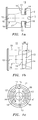
- FIGS. 1a-1c
- A diagram of the fixture base of the present invention.
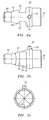
- FIGS. 2a-2c
- A diagram of the fixture mount of the present invention.
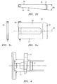
- FIGS. 3a-3c
- A diagram of the dual wedge of the present invention.
- FIG. 4
- A diagram illustrating the interaction of the fixture mount, the fixture base, and the dual wedge of the present invention.
- It is a central aspect of the present invention to provide a double wedge design for use in fixture locators. The dual wedges of the present invention have two long locating surfaces along the machined detail. Each detail is easily replaceable rather than scrapping out entire fixtures when they get too bent.
- With reference to FIGS. 1a-1c, there is illustrated the
fixture base 11 of the present invention. Fixturebase 11 is symmetrically disposed about abase centerline 10. In a preferred embodiment,fixture base 11 is cylindrical in form. By "cylindrical", it is meant that the outer surface offixture base 11 is cylindrical in form but for minor deviations from a perfect cylindrical form owing to the fabrication of thebase wedge slots 13 and alignment recess 15 as described more fully below.Fixture base 11 contains a firstreceptive chamber 17 open to oneend 2 offixture base 11 and extending a distance intofixture base 11 alongbase centerline 10. In a preferred embodiment, firstreceptive chamber 17 is conical in form and symmetrically disposed aboutbase centerline 10. Most preferred, firstreceptive chamber 17 forms a frustum. Firstreceptive chamber 17 extends so as to carve out a chamber infixture base 11, creating a firstreceptive chamber surface 18. As will be described more fully below, it is this first receptive chamber that accepts, and into which is inserted,first mating member 27. In a preferred embodiment, a secondreceptive chamber 16 extends alongbase centerline 10 away from the firstreceptive chamber 17. In the preferred embodiment, secondreceptive chamber 16 creates a secondreceptive chamber surface 12 symmetrically disposed aboutbase centerline 10. In such an embodiment, secondreceptive chamber 16 accepts, and into which may be inserted,second mating member 26 as discussed more fully below. - Two
base wedge slots 13, 13' extend intofixture base 11. Thebase wedge slots 13, 13' extend primarily perpendicular tobase centerline 10 and intersect not only an outer surface offixture base 11, but also extend through the firstreceptive chamber surface 18. By extending in this fashion, eachbase wedge slot 13 forms a first and secondbase slot boundary 14, 14'. Both the first and secondbase slot boundary 14, 14' reside in planar fashion inclined to one another by awedge angle 22. In a preferred embodiment, this wedge angle is between 4° and 7°, most preferably approximately 5°. - In a preferred embodiment,
fixture base 11 has analignment recess 15. As will be discussed more fully below,alignment recess 15 is constructed so as to acceptalignment member 25 located uponmachine mount tool 21. By accepting thealignment member 25 in this fashion, alignment recess 15 assures alignment of themachine tool mount 21 with thefixture base 11 in a desired configuration. - With reference to FIGS. 2A-2C, there is illustrated the
machine tool mount 21 of the present invention.Machine tool mount 21 comprises afirst mating member 27, which extends along amount centerline 20. In a preferred embodiment,first mating member 27 is conical in form. Most preferably,first mating member 27 forms a frustum which corresponds in dimensions to that of the firstreceptive chamber 17. Extending perpendicular to themount centerline 20, are twomount wedge slots 23, 23'. Whenmachine tool mount 21 is inserted intofixture base 11, themount wedge slots 23, 23' are capable of being aligned with thebase wedge slots 13, 13' such that thedual wedge 31 of the present invention, described more fully below, may be inserted in contact with the planar surfaces forming themount wedge slots 23, 23' and thebase wedge slots 13, 13'.
In a preferred embodiment, machine tool mount 21 further comprises asecond mating member 26 extending alongmount centerline 20 away fromfirst mating member 27.Second mating member 26 corresponds in dimensions to the recess formed by the secondreceptive chamber 12 offixture base 11. As a result, whenmachine tool mount 21 is extended intofixture base 11, both afirst mating member 27 and asecond mating member 26 fit in secondreceptive chamber 16 and firstreceptive chamber 17, respectively, such that secondreceptive chamber surface 12 and firstreceptive chamber surface 18 rest in contact with the outer surfaces ofsecond mating member 26 andfirst mating member 27. -
Alignment member 25 protrudes fromfirst mating member 27. In a preferred embodiment,alignment member 25 is cylindrical in form, and of a dimension to fit tightly withinalignment recess 15. In such an embodiment,alignment recess 15 is additionally a semi-circular recess. While illustrated as cylindrical in form and semi-circular in form,alignment member 25 andalignment recess 15 may be of any shape sufficient to allow insertion ofalignment member 25 intoalignment recess 15 so as to prevent rotation of the machine tool mount 21 aboutmount centerline 20 when inserted intofixture base 11. - When
machine tool mount 21 is inserted intofixture base 11,mount centerline 20 andbase centerline 10 are both parallel and congruent. That is to say both centerlines are in close conformity in space with one another. In addition, oncealignment member 25 is inserted intoalignment recess 15,machine tool mount 21 is prevented from rotating aboutmount centerline 20. - In order to assure that
machine tool mount 21, once inserted intofixture base 11, does not detach fromfixture base 11, there is provided thedual wedge 31 of the present invention, as illustrated in FIGS. 3A-3C.Dual wedge 31 consists of first and second wedge prongs 33, 33'. Each of said first and second wedge prongs 33, 33' have a first end connected to awedge bridge 37 and a second end.Wedge bridge 37 connects the first ends of the wedge prongs forming a U-shaped formation. The two wedge prongs are symmetrically disposed about awedge centerline 39. In addition, eachwedge prong 33 consists of afront surface 34 and aback surface 32.Front surface 34 and back surface 32 are planar in construction and inclined to one another bywedge angle 22. Note that first and secondbase slot boundaries 14, 14' are inclined to one another by thewedge angle 22, and thefront surface 34 and back surface 32 of thedual wedge 31 is inclined at thewedge angle 22. As a result, the first and second wedge prongs of thedual wedge 31 may be inserted into thebase wedge slots 13 and themount wedge slots 23 forming close contact with the first and secondbase slot boundaries 14, 14' as well as the surfaces comprisingmount wedge slot 23 to form a tight seal along the surface areas comprising the aforementioned areas. After extending into thebase wedge slots 13, 13' and themount wedge slots 23, 23',dual wedge 31 is secured to prevent removal from the aforementioned configuration, by fasteningmember 35. Fasteningmember 35 may be any form of fastener sufficient to prevent the removal of thedual wedge 31 from contact with thefixture base 11 and the machine tool mount 21 so as to assure their continued tight fit one with the other. In a preferred embodiment,fastening member 35 forms a pin which may be inserted through a second end of both wedge prongs 33, 33'. Once inserted through the ends ofwedge prong 33,fastening member 35 may be secured in place to prevent removal through the use of a pin, clamp, or other such article. - With reference to Figure 4, there is illustrated an assembled fixture located of the present invention.
- It is apparent that there has been provided in accordance with the present invention an apparatus for securing a fixture base to a fixture mount via a dual wedge which fully satisfies the objects, means, and advantages set forth previously herein. Specifically, it is contemplated that one could combine any number of techniques disclosed herein to further satisfy the object of the present invention. While the present invention has been described in the context of specific embodiments thereof, other alternatives, modifications, and variations will become apparent to those skilled in the art having read the foregoing description. Accordingly, it is intended to embrace those alternatives, modifications, and variations as fall within the broad scope of the appended claims.
Claims (23)
- A fixture locator, comprising:a fixture base (11), comprising:a first receptive chamber (17) extending along a base centerline (10) comprising a first receptive surface (18); andtwo base wedge slots (13,13') extending into said fixture base (11) and intersecting said first receptive surface (18);a machine tool mount (21), comprising:a first mating member (27) extending along a mount centerline (20) comprising an outer surface adapted to fit within said first receptive chamber (17) such that said mount centerline (20) is congruent with said base centerline (10); andtwo mount wedge slots (23,23') extending into said machine tool mount (21);a dual wedge (31), comprising:a first wedge prong (33) and a second wedge prong (33') each comprising a first and a second end symmetrically disposed about a wedge centerline (39);a wedge bridge (37) adapted to connect said first ends of said first and second wedge prongs (33,33'); anda fastening member (35) adapted to removably fasten said second ends of said first and second wedge prongs (33,33') wherein each of said first and second wedge prongs (33,33') are adapted to extend in contact with one of said base wedge slots (13,13') and said mount wedge slots (23,23').
- The fixture locator of claim 1 wherein said fixture base (11) is cylindrically disposed about said base centerline (10).
- The fixture locator of claim 1 or 2 wherein said first receptive chamber (17) comprises a frustum.
- The fixture locator of any preceding claim wherein said two base wedge slots (13,13') each form a first and a second planar base slot boundary (14,14') angularly inclined to one another by a wedge angle (22).
- The fixture locator of claim 5 wherein each of said first and second wedge prongs (33,33') comprises a front surface (34) and a rear surface (32) angularly inclined to one another by said wedge angle (22).
- The fixture locator of any preceding claim wherein said fixture base (11) additionally comprises a second receptive chamber (16) away from said first receptive chamber (17) along said base centerline (10) and comprising a second receptive chamber surface (12).
- The fixture location of claim 6 wherein said machine tool mount (21) additional comprises a second mating member (26) extending along said mount centerline (20) away from said first mating member (27) and adapted to fit within said second receptive chamber (16).
- The fixture locator of any preceding claim wherein said fixture base (11) additionally comprises an alignment recess (15).
- The fixture locator of claim 8 wherein said alignment recess (15) is semi-circular.
- The fixture locator of claim 8 or 9 wherein said machine tool mount (21) comprises an alignment member (25) adapted to be inserted into said alignment recess (15) .
- The fixture locator of any preceding claim wherein said fastening member comprises a pin (35).
- A fixture base (11) for use in a fixture locator comprising:a first receptive chamber (17) extending along a base centerline (10) comprising a first receptive surface (18); andtwo base wedge slots (13,13') extending into said fixture base (11) and intersecting said first receptive surface (18).
- The fixture base of claim 12 wherein said fixture base (11) is cylindrically disposed about said base centerline (10).
- The fixture base of claim 12 or 13 wherein said first receptive chamber (17) comprises a frustum.
- The fixture base of claim 12, 13 or 14, wherein said fixture base (11) additionally comprises a second receptive chamber (16) away from said first receptive chamber (17) along said base centerline (10) and comprising a second receptive chamber surface (12).
- The fixture base of any of claims 12 to 15 wherein said fixture base (11) additionally comprises an alignment recess (15).
- The fixture base of claim 16 wherein said alignment recess (15) is semi-circular.
- The fixture base of any of claims 12 to 17 wherein said two base wedge slots (13,13') each form a first and a second planar base slot boundary (14,14') angularly inclined to one another by a wedge angle (22).
- A machine tool mount (21) for use in a fixture locator, comprising:a first mating member (27) extending along a mount centerline (20) comprising an outer surface; andtwo mount wedge slots (23,23') extending into said machine tool mount.
- The machine tool mount of claim 19 wherein said machine tool mount (21) additional comprises a second mating member (26) extending along said mount centerline (10) away from said first mating member (27).
- The machine tool mount of claim 19 or 20 wherein said machine tool mount (21) comprises an alignment member (25).
- A dual wedge (31) for use in a fixture locator, comprising:a first wedge prong (33) and a second wedge prong (33') each comprising a first and a second end symmetrically disposed about a wedge centerline (39);a wedge bridge (35) adapted to connect said first ends of said first and second wedge prongs (33,33'); anda fastening member (35) adapted to removably fasten said second ends of said first and second wedge prongs (33,33').
- The dual wedge of claim 22 wherein each of said first and second wedge prongs (33,33') comprises a front surface (34) and a rear surface (32) angularly inclined to one another by a wedge angle (22).
Applications Claiming Priority (2)
| Application Number | Priority Date | Filing Date | Title |
|---|---|---|---|
| US449303 | 1999-11-24 | ||
| US10/449,303 US6981334B2 (en) | 2003-05-29 | 2003-05-29 | Dual wedge fixture locator |
Publications (2)
| Publication Number | Publication Date |
|---|---|
| EP1481757A1 true EP1481757A1 (en) | 2004-12-01 |
| EP1481757B1 EP1481757B1 (en) | 2009-02-18 |
Family
ID=33131632
Family Applications (1)
| Application Number | Title | Priority Date | Filing Date |
|---|---|---|---|
| EP04253201A Expired - Lifetime EP1481757B1 (en) | 2003-05-29 | 2004-05-28 | Dual wedge fixture locator |
Country Status (6)
| Country | Link |
|---|---|
| US (1) | US6981334B2 (en) |
| EP (1) | EP1481757B1 (en) |
| JP (1) | JP2005046992A (en) |
| AT (1) | ATE422985T1 (en) |
| CA (1) | CA2468682A1 (en) |
| DE (1) | DE602004019471D1 (en) |
Families Citing this family (4)
| Publication number | Priority date | Publication date | Assignee | Title |
|---|---|---|---|---|
| JP5020726B2 (en) * | 2007-07-06 | 2012-09-05 | ナイルス株式会社 | Locking structure between two members |
| CN101982266A (en) * | 2010-09-10 | 2011-03-02 | 长春轨道客车股份有限公司 | Method for assembling externally unlocking lock of sliding door of motor train unit and special positioning plates |
| CN103846254B (en) * | 2013-12-03 | 2017-01-11 | 西南石油大学 | Cleaner for outer anticorrosive insulating layer of pipeline |
| CN117340638B (en) * | 2023-08-21 | 2026-04-28 | 昌河飞机工业(集团)有限责任公司 | A wedge-shaped clamping device |
Citations (2)
| Publication number | Priority date | Publication date | Assignee | Title |
|---|---|---|---|---|
| US4545230A (en) * | 1983-12-27 | 1985-10-08 | Anderson-Cook, Inc. | Rotary forming machine having tie bar connection |
| WO1999006172A2 (en) * | 1997-08-01 | 1999-02-11 | Briese Leonard A | Taper lock arrangement |
Family Cites Families (16)
| Publication number | Priority date | Publication date | Assignee | Title |
|---|---|---|---|---|
| US140715A (en) * | 1873-04-03 | 1873-07-08 | Lahman William | Improvement in plow-clevises |
| US1064715A (en) * | 1910-05-11 | 1913-06-17 | Gen Electric | Machine for cutting out mica between segments in commutators. |
| US3650053A (en) * | 1969-05-07 | 1972-03-21 | Bucyrus Erie Co | Roller lock for digging tooth assembly |
| US3606406A (en) * | 1969-11-26 | 1971-09-20 | Keystone Consolidated Ind Inc | Snap action retainer |
| US3908477A (en) * | 1974-10-11 | 1975-09-30 | Fritz Teske | Link chain |
| US4477202A (en) * | 1983-10-13 | 1984-10-16 | Price John G | Pin lock |
| SE464175B (en) * | 1989-05-03 | 1991-03-18 | Morgaardshammar Ab | PROCEDURE FOR ASSEMBLING A ROLLING RING ON A ROLLER SHAFT AND AN ASSEMBLY PIECE TO PERFORM THE PROCEDURE |
| US4929113A (en) * | 1989-05-30 | 1990-05-29 | Sheu Yin Ping | Knuckle joint |
| US6439797B1 (en) * | 1993-12-01 | 2002-08-27 | John G. Campbell | Fastener and fastener-rod assembly |
| US5584212A (en) * | 1994-08-08 | 1996-12-17 | Hi-Lex Corporation | Cable end fitting with simplified assembly |
| US6099197A (en) * | 1995-11-09 | 2000-08-08 | Gauron; Jacques P. | Locking spring-biased latch |
| KR100208492B1 (en) * | 1996-12-20 | 1999-07-15 | 정몽규 | Piston ring clearance measuring device for vehicle |
| US6254303B1 (en) * | 1999-02-01 | 2001-07-03 | Bogdan S. Falat | Quick-release connector and methods therefore |
| US6604883B2 (en) * | 2000-09-28 | 2003-08-12 | Du-Bro Products, Inc. | Universal connector for remote control vehicles |
| US6718645B2 (en) * | 2001-06-01 | 2004-04-13 | Heinz Berger | Measuring tool and adjusting tool for ammunition |
| DE10152959B4 (en) * | 2001-10-26 | 2007-03-15 | Robert Bosch Gmbh | Hand tool |
-
2003
- 2003-05-29 US US10/449,303 patent/US6981334B2/en not_active Expired - Lifetime
-
2004
- 2004-05-27 CA CA002468682A patent/CA2468682A1/en not_active Abandoned
- 2004-05-28 EP EP04253201A patent/EP1481757B1/en not_active Expired - Lifetime
- 2004-05-28 DE DE602004019471T patent/DE602004019471D1/en not_active Expired - Lifetime
- 2004-05-28 AT AT04253201T patent/ATE422985T1/en not_active IP Right Cessation
- 2004-05-31 JP JP2004160524A patent/JP2005046992A/en not_active Ceased
Patent Citations (2)
| Publication number | Priority date | Publication date | Assignee | Title |
|---|---|---|---|---|
| US4545230A (en) * | 1983-12-27 | 1985-10-08 | Anderson-Cook, Inc. | Rotary forming machine having tie bar connection |
| WO1999006172A2 (en) * | 1997-08-01 | 1999-02-11 | Briese Leonard A | Taper lock arrangement |
Also Published As
| Publication number | Publication date |
|---|---|
| CA2468682A1 (en) | 2004-11-29 |
| US6981334B2 (en) | 2006-01-03 |
| JP2005046992A (en) | 2005-02-24 |
| EP1481757B1 (en) | 2009-02-18 |
| DE602004019471D1 (en) | 2009-04-02 |
| US20040237324A1 (en) | 2004-12-02 |
| ATE422985T1 (en) | 2009-03-15 |
Similar Documents
| Publication | Publication Date | Title |
|---|---|---|
| US8992142B2 (en) | Self-clamping cutting head for releasably mounting on a cutting tool | |
| TWI736664B (en) | Tool shank with head support surface having central recess provided with resiliently displaceable abutment portions, rotary cutting tool and method of assembling the rotary cutting tool | |
| JP2004501785A (en) | Rotatable tool with interchangeable tips at the chip removal free end | |
| JP2009262323A (en) | Tool holder for holding metal cutting insert | |
| US4688652A (en) | Braze fixtures for use in drilling tools | |
| EP1163424A1 (en) | Cutting tool holder assembly | |
| KR101714853B1 (en) | Left-handed and right-handed cutting tool | |
| PL177379B1 (en) | Tool holder accommodating fixing surface with projections | |
| EP1481757A1 (en) | Dual wedge fixture locator | |
| JP2002174103A (en) | Tool for holding turbine blade | |
| CN101298125B (en) | Method and apparatus for fabricating a plurality of turbine components | |
| JP4861984B2 (en) | Tool holder assembly | |
| US6912755B2 (en) | Clamping device of a rotating tool | |
| WO1998003310A1 (en) | Tube welding fixture and heat shield | |
| JP2002066944A (en) | Reaction cam system used for release system, and method for releasing reaction force | |
| JP2005000985A (en) | Friction welding workpiece chuck structure | |
| EP3600739B1 (en) | Multifunction tip | |
| CN221935393U (en) | Steering knuckle machining cutter with clearance | |
| CN221657999U (en) | Easy-crushing grain variable-diameter turning clamp | |
| TWI740671B (en) | Locking sleeve | |
| KR100303854B1 (en) | Base plate of pipe clamp | |
| CN211594272U (en) | Connecting device of tongs of breaking a jam | |
| KR200341681Y1 (en) | Connector for Construct | |
| JPH0611750Y2 (en) | Holding mechanism for ultrasonic machining tools | |
| FR2529126A1 (en) | Cylindrical tool shank holder with lateral locking - has outer reinforcing sleeve tapped to receive lock screw passing through holder |
Legal Events
| Date | Code | Title | Description |
|---|---|---|---|
| PUAI | Public reference made under article 153(3) epc to a published international application that has entered the european phase |
Free format text: ORIGINAL CODE: 0009012 |
|
| AK | Designated contracting states |
Kind code of ref document: A1 Designated state(s): AT BE BG CH CY CZ DE DK EE ES FI FR GB GR HU IE IT LI LU MC NL PL PT RO SE SI SK TR |
|
| AX | Request for extension of the european patent |
Extension state: AL HR LT LV MK |
|
| 17P | Request for examination filed |
Effective date: 20050113 |
|
| AKX | Designation fees paid |
Designated state(s): AT BE BG CH CY CZ DE DK EE ES FI FR GB GR HU IE IT LI LU MC NL PL PT RO SE SI SK TR |
|
| 17Q | First examination report despatched |
Effective date: 20071114 |
|
| GRAP | Despatch of communication of intention to grant a patent |
Free format text: ORIGINAL CODE: EPIDOSNIGR1 |
|
| GRAS | Grant fee paid |
Free format text: ORIGINAL CODE: EPIDOSNIGR3 |
|
| GRAA | (expected) grant |
Free format text: ORIGINAL CODE: 0009210 |
|
| AK | Designated contracting states |
Kind code of ref document: B1 Designated state(s): AT BE BG CH CY CZ DE DK EE ES FI FR GB GR HU IE IT LI LU MC NL PL PT RO SE SI SK TR |
|
| REG | Reference to a national code |
Ref country code: GB Ref legal event code: FG4D |
|
| REG | Reference to a national code |
Ref country code: CH Ref legal event code: EP |
|
| REG | Reference to a national code |
Ref country code: IE Ref legal event code: FG4D |
|
| REF | Corresponds to: |
Ref document number: 602004019471 Country of ref document: DE Date of ref document: 20090402 Kind code of ref document: P |
|
| PG25 | Lapsed in a contracting state [announced via postgrant information from national office to epo] |
Ref country code: NL Free format text: LAPSE BECAUSE OF FAILURE TO SUBMIT A TRANSLATION OF THE DESCRIPTION OR TO PAY THE FEE WITHIN THE PRESCRIBED TIME-LIMIT Effective date: 20090218 Ref country code: FI Free format text: LAPSE BECAUSE OF FAILURE TO SUBMIT A TRANSLATION OF THE DESCRIPTION OR TO PAY THE FEE WITHIN THE PRESCRIBED TIME-LIMIT Effective date: 20090218 Ref country code: ES Free format text: LAPSE BECAUSE OF FAILURE TO SUBMIT A TRANSLATION OF THE DESCRIPTION OR TO PAY THE FEE WITHIN THE PRESCRIBED TIME-LIMIT Effective date: 20090529 Ref country code: SI Free format text: LAPSE BECAUSE OF FAILURE TO SUBMIT A TRANSLATION OF THE DESCRIPTION OR TO PAY THE FEE WITHIN THE PRESCRIBED TIME-LIMIT Effective date: 20090218 |
|
| NLV1 | Nl: lapsed or annulled due to failure to fulfill the requirements of art. 29p and 29m of the patents act | ||
| PG25 | Lapsed in a contracting state [announced via postgrant information from national office to epo] |
Ref country code: SE Free format text: LAPSE BECAUSE OF FAILURE TO SUBMIT A TRANSLATION OF THE DESCRIPTION OR TO PAY THE FEE WITHIN THE PRESCRIBED TIME-LIMIT Effective date: 20090518 Ref country code: AT Free format text: LAPSE BECAUSE OF FAILURE TO SUBMIT A TRANSLATION OF THE DESCRIPTION OR TO PAY THE FEE WITHIN THE PRESCRIBED TIME-LIMIT Effective date: 20090218 Ref country code: PL Free format text: LAPSE BECAUSE OF FAILURE TO SUBMIT A TRANSLATION OF THE DESCRIPTION OR TO PAY THE FEE WITHIN THE PRESCRIBED TIME-LIMIT Effective date: 20090218 |
|
| PG25 | Lapsed in a contracting state [announced via postgrant information from national office to epo] |
Ref country code: BE Free format text: LAPSE BECAUSE OF FAILURE TO SUBMIT A TRANSLATION OF THE DESCRIPTION OR TO PAY THE FEE WITHIN THE PRESCRIBED TIME-LIMIT Effective date: 20090218 |
|
| PG25 | Lapsed in a contracting state [announced via postgrant information from national office to epo] |
Ref country code: EE Free format text: LAPSE BECAUSE OF FAILURE TO SUBMIT A TRANSLATION OF THE DESCRIPTION OR TO PAY THE FEE WITHIN THE PRESCRIBED TIME-LIMIT Effective date: 20090218 Ref country code: CZ Free format text: LAPSE BECAUSE OF FAILURE TO SUBMIT A TRANSLATION OF THE DESCRIPTION OR TO PAY THE FEE WITHIN THE PRESCRIBED TIME-LIMIT Effective date: 20090218 Ref country code: DK Free format text: LAPSE BECAUSE OF FAILURE TO SUBMIT A TRANSLATION OF THE DESCRIPTION OR TO PAY THE FEE WITHIN THE PRESCRIBED TIME-LIMIT Effective date: 20090218 Ref country code: PT Free format text: LAPSE BECAUSE OF FAILURE TO SUBMIT A TRANSLATION OF THE DESCRIPTION OR TO PAY THE FEE WITHIN THE PRESCRIBED TIME-LIMIT Effective date: 20090727 |
|
| PG25 | Lapsed in a contracting state [announced via postgrant information from national office to epo] |
Ref country code: RO Free format text: LAPSE BECAUSE OF FAILURE TO SUBMIT A TRANSLATION OF THE DESCRIPTION OR TO PAY THE FEE WITHIN THE PRESCRIBED TIME-LIMIT Effective date: 20090218 Ref country code: SK Free format text: LAPSE BECAUSE OF FAILURE TO SUBMIT A TRANSLATION OF THE DESCRIPTION OR TO PAY THE FEE WITHIN THE PRESCRIBED TIME-LIMIT Effective date: 20090218 |
|
| PLBE | No opposition filed within time limit |
Free format text: ORIGINAL CODE: 0009261 |
|
| STAA | Information on the status of an ep patent application or granted ep patent |
Free format text: STATUS: NO OPPOSITION FILED WITHIN TIME LIMIT |
|
| PG25 | Lapsed in a contracting state [announced via postgrant information from national office to epo] |
Ref country code: MC Free format text: LAPSE BECAUSE OF NON-PAYMENT OF DUE FEES Effective date: 20090531 |
|
| REG | Reference to a national code |
Ref country code: CH Ref legal event code: PL |
|
| 26N | No opposition filed |
Effective date: 20091119 |
|
| PG25 | Lapsed in a contracting state [announced via postgrant information from national office to epo] |
Ref country code: CH Free format text: LAPSE BECAUSE OF NON-PAYMENT OF DUE FEES Effective date: 20090531 Ref country code: LI Free format text: LAPSE BECAUSE OF NON-PAYMENT OF DUE FEES Effective date: 20090531 Ref country code: BG Free format text: LAPSE BECAUSE OF FAILURE TO SUBMIT A TRANSLATION OF THE DESCRIPTION OR TO PAY THE FEE WITHIN THE PRESCRIBED TIME-LIMIT Effective date: 20090518 |
|
| REG | Reference to a national code |
Ref country code: FR Ref legal event code: ST Effective date: 20100129 |
|
| PG25 | Lapsed in a contracting state [announced via postgrant information from national office to epo] |
Ref country code: FR Free format text: LAPSE BECAUSE OF NON-PAYMENT OF DUE FEES Effective date: 20090602 Ref country code: IE Free format text: LAPSE BECAUSE OF NON-PAYMENT OF DUE FEES Effective date: 20090528 |
|
| PG25 | Lapsed in a contracting state [announced via postgrant information from national office to epo] |
Ref country code: GR Free format text: LAPSE BECAUSE OF FAILURE TO SUBMIT A TRANSLATION OF THE DESCRIPTION OR TO PAY THE FEE WITHIN THE PRESCRIBED TIME-LIMIT Effective date: 20090519 |
|
| PG25 | Lapsed in a contracting state [announced via postgrant information from national office to epo] |
Ref country code: IT Free format text: LAPSE BECAUSE OF FAILURE TO SUBMIT A TRANSLATION OF THE DESCRIPTION OR TO PAY THE FEE WITHIN THE PRESCRIBED TIME-LIMIT Effective date: 20090218 |
|
| PG25 | Lapsed in a contracting state [announced via postgrant information from national office to epo] |
Ref country code: LU Free format text: LAPSE BECAUSE OF NON-PAYMENT OF DUE FEES Effective date: 20090528 |
|
| PG25 | Lapsed in a contracting state [announced via postgrant information from national office to epo] |
Ref country code: HU Free format text: LAPSE BECAUSE OF FAILURE TO SUBMIT A TRANSLATION OF THE DESCRIPTION OR TO PAY THE FEE WITHIN THE PRESCRIBED TIME-LIMIT Effective date: 20090819 |
|
| PG25 | Lapsed in a contracting state [announced via postgrant information from national office to epo] |
Ref country code: TR Free format text: LAPSE BECAUSE OF FAILURE TO SUBMIT A TRANSLATION OF THE DESCRIPTION OR TO PAY THE FEE WITHIN THE PRESCRIBED TIME-LIMIT Effective date: 20090218 |
|
| PG25 | Lapsed in a contracting state [announced via postgrant information from national office to epo] |
Ref country code: CY Free format text: LAPSE BECAUSE OF FAILURE TO SUBMIT A TRANSLATION OF THE DESCRIPTION OR TO PAY THE FEE WITHIN THE PRESCRIBED TIME-LIMIT Effective date: 20090218 |
|
| REG | Reference to a national code |
Ref country code: DE Ref legal event code: R082 Ref document number: 602004019471 Country of ref document: DE Representative=s name: SCHMITT-NILSON SCHRAUD WAIBEL WOHLFROM PATENTA, DE |
|
| REG | Reference to a national code |
Ref country code: DE Ref legal event code: R082 Ref document number: 602004019471 Country of ref document: DE Representative=s name: SCHMITT-NILSON SCHRAUD WAIBEL WOHLFROM PATENTA, DE Ref country code: DE Ref legal event code: R081 Ref document number: 602004019471 Country of ref document: DE Owner name: UNITED TECHNOLOGIES CORP. (N.D.GES.D. STAATES , US Free format text: FORMER OWNER: UNITED TECHNOLOGIES CORP., HARTFORD, CONN., US |
|
| PGFP | Annual fee paid to national office [announced via postgrant information from national office to epo] |
Ref country code: DE Payment date: 20190418 Year of fee payment: 16 |
|
| REG | Reference to a national code |
Ref country code: DE Ref legal event code: R119 Ref document number: 602004019471 Country of ref document: DE |
|
| PG25 | Lapsed in a contracting state [announced via postgrant information from national office to epo] |
Ref country code: DE Free format text: LAPSE BECAUSE OF NON-PAYMENT OF DUE FEES Effective date: 20201201 |
|
| PGFP | Annual fee paid to national office [announced via postgrant information from national office to epo] |
Ref country code: GB Payment date: 20230420 Year of fee payment: 20 |
|
| REG | Reference to a national code |
Ref country code: GB Ref legal event code: PE20 Expiry date: 20240527 |
|
| PG25 | Lapsed in a contracting state [announced via postgrant information from national office to epo] |
Ref country code: GB Free format text: LAPSE BECAUSE OF EXPIRATION OF PROTECTION Effective date: 20240527 |
|
| PG25 | Lapsed in a contracting state [announced via postgrant information from national office to epo] |
Ref country code: GB Free format text: LAPSE BECAUSE OF EXPIRATION OF PROTECTION Effective date: 20240527 |