EP1481737A1 - Coater and method for producing coated sheet and air floating mini-turn bar - Google Patents
Coater and method for producing coated sheet and air floating mini-turn bar Download PDFInfo
- Publication number
- EP1481737A1 EP1481737A1 EP03743587A EP03743587A EP1481737A1 EP 1481737 A1 EP1481737 A1 EP 1481737A1 EP 03743587 A EP03743587 A EP 03743587A EP 03743587 A EP03743587 A EP 03743587A EP 1481737 A1 EP1481737 A1 EP 1481737A1
- Authority
- EP
- European Patent Office
- Prior art keywords
- web
- air
- turn bar
- bar
- Prior art date
- Legal status (The legal status is an assumption and is not a legal conclusion. Google has not performed a legal analysis and makes no representation as to the accuracy of the status listed.)
- Withdrawn
Links
Images










Classifications
-
- B—PERFORMING OPERATIONS; TRANSPORTING
- B65—CONVEYING; PACKING; STORING; HANDLING THIN OR FILAMENTARY MATERIAL
- B65H—HANDLING THIN OR FILAMENTARY MATERIAL, e.g. SHEETS, WEBS, CABLES
- B65H23/00—Registering, tensioning, smoothing or guiding webs
- B65H23/04—Registering, tensioning, smoothing or guiding webs longitudinally
- B65H23/24—Registering, tensioning, smoothing or guiding webs longitudinally by fluid action, e.g. to retard the running web
-
- B—PERFORMING OPERATIONS; TRANSPORTING
- B05—SPRAYING OR ATOMISING IN GENERAL; APPLYING FLUENT MATERIALS TO SURFACES, IN GENERAL
- B05C—APPARATUS FOR APPLYING FLUENT MATERIALS TO SURFACES, IN GENERAL
- B05C1/00—Apparatus in which liquid or other fluent material is applied to the surface of the work by contact with a member carrying the liquid or other fluent material, e.g. a porous member loaded with a liquid to be applied as a coating
- B05C1/04—Apparatus in which liquid or other fluent material is applied to the surface of the work by contact with a member carrying the liquid or other fluent material, e.g. a porous member loaded with a liquid to be applied as a coating for applying liquid or other fluent material to work of indefinite length
- B05C1/08—Apparatus in which liquid or other fluent material is applied to the surface of the work by contact with a member carrying the liquid or other fluent material, e.g. a porous member loaded with a liquid to be applied as a coating for applying liquid or other fluent material to work of indefinite length using a roller or other rotating member which contacts the work along a generating line
- B05C1/0826—Apparatus in which liquid or other fluent material is applied to the surface of the work by contact with a member carrying the liquid or other fluent material, e.g. a porous member loaded with a liquid to be applied as a coating for applying liquid or other fluent material to work of indefinite length using a roller or other rotating member which contacts the work along a generating line the work being a web or sheets
- B05C1/083—Apparatus in which liquid or other fluent material is applied to the surface of the work by contact with a member carrying the liquid or other fluent material, e.g. a porous member loaded with a liquid to be applied as a coating for applying liquid or other fluent material to work of indefinite length using a roller or other rotating member which contacts the work along a generating line the work being a web or sheets being passed between the coating roller and one or more backing rollers
-
- B—PERFORMING OPERATIONS; TRANSPORTING
- B05—SPRAYING OR ATOMISING IN GENERAL; APPLYING FLUENT MATERIALS TO SURFACES, IN GENERAL
- B05C—APPARATUS FOR APPLYING FLUENT MATERIALS TO SURFACES, IN GENERAL
- B05C13/00—Means for manipulating or holding work, e.g. for separate articles
-
- B—PERFORMING OPERATIONS; TRANSPORTING
- B65—CONVEYING; PACKING; STORING; HANDLING THIN OR FILAMENTARY MATERIAL
- B65H—HANDLING THIN OR FILAMENTARY MATERIAL, e.g. SHEETS, WEBS, CABLES
- B65H23/00—Registering, tensioning, smoothing or guiding webs
- B65H23/04—Registering, tensioning, smoothing or guiding webs longitudinally
- B65H23/32—Arrangements for turning or reversing webs
-
- D—TEXTILES; PAPER
- D21—PAPER-MAKING; PRODUCTION OF CELLULOSE
- D21H—PULP COMPOSITIONS; PREPARATION THEREOF NOT COVERED BY SUBCLASSES D21C OR D21D; IMPREGNATING OR COATING OF PAPER; TREATMENT OF FINISHED PAPER NOT COVERED BY CLASS B31 OR SUBCLASS D21G; PAPER NOT OTHERWISE PROVIDED FOR
- D21H25/00—After-treatment of paper not provided for in groups D21H17/00 - D21H23/00
- D21H25/08—Rearranging applied substances, e.g. metering, smoothing; Removing excess material
- D21H25/16—Rearranging applied substances, e.g. metering, smoothing; Removing excess material with a blast of vapour or gas, e.g. air knife
-
- B—PERFORMING OPERATIONS; TRANSPORTING
- B05—SPRAYING OR ATOMISING IN GENERAL; APPLYING FLUENT MATERIALS TO SURFACES, IN GENERAL
- B05C—APPARATUS FOR APPLYING FLUENT MATERIALS TO SURFACES, IN GENERAL
- B05C9/00—Apparatus or plant for applying liquid or other fluent material to surfaces by means not covered by any preceding group, or in which the means of applying the liquid or other fluent material is not important
- B05C9/04—Apparatus or plant for applying liquid or other fluent material to surfaces by means not covered by any preceding group, or in which the means of applying the liquid or other fluent material is not important for applying liquid or other fluent material to opposite sides of the work
-
- B—PERFORMING OPERATIONS; TRANSPORTING
- B65—CONVEYING; PACKING; STORING; HANDLING THIN OR FILAMENTARY MATERIAL
- B65H—HANDLING THIN OR FILAMENTARY MATERIAL, e.g. SHEETS, WEBS, CABLES
- B65H2404/00—Parts for transporting or guiding the handled material
- B65H2404/50—Surface of the elements in contact with the forwarded or guided material
- B65H2404/55—Built-up surface, e.g. arrangement for attaching the surface to the forwarding or guiding element
- B65H2404/552—Built-up surface, e.g. arrangement for attaching the surface to the forwarding or guiding element permanent attachment
- B65H2404/5521—Coating
-
- D—TEXTILES; PAPER
- D21—PAPER-MAKING; PRODUCTION OF CELLULOSE
- D21H—PULP COMPOSITIONS; PREPARATION THEREOF NOT COVERED BY SUBCLASSES D21C OR D21D; IMPREGNATING OR COATING OF PAPER; TREATMENT OF FINISHED PAPER NOT COVERED BY CLASS B31 OR SUBCLASS D21G; PAPER NOT OTHERWISE PROVIDED FOR
- D21H23/00—Processes or apparatus for adding material to the pulp or to the paper
- D21H23/02—Processes or apparatus for adding material to the pulp or to the paper characterised by the manner in which substances are added
- D21H23/22—Addition to the formed paper
- D21H23/52—Addition to the formed paper by contacting paper with a device carrying the material
- D21H23/56—Rolls
Definitions
- the present invention relates to an apparatus and method, which are used in paper-making machines, resin-film manufacturing machines, etc., for applying a coating solution to the surface of a web such as paper, resin film, etc., and also relates to an air-flotation type mini turn bar that is suitably used in the coating apparatus.
- an apparatus for applying a coating solution to the surface of a web such as paper, resin film, etc. In paper-making machines, resin-film manufacturing machines, etc., there is provided an apparatus for applying a coating solution to the surface of a web such as paper, resin film, etc.
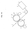
- Fig. 14 is a simplified side view showing a conventional coating apparatus.
- a web 1 such as paper, etc.
- a web 1 is fed from a previous step and passes between the web-nipping portions 20 of two applicator rolls 2 which are formed when they are pressed against each other.
- the web 1 After the web 1 is coated with a coating solution, it goes into a drier 6 via a turn bar (air-flotation/non-contact type web-travel supporting unit) 5 that conveys the web 1 while floating it.
- a turn bar air-flotation/non-contact type web-travel supporting unit
- Each applicator roll 2 includes a main body 2a made of metal such as steel, etc.
- the roll main body 2a has an elastic film 2b such as a film of rubber on the outer periphery.
- Each applicator roll 2 rotates at the same circumferential speed as the travel speed of the web 1.
- the applicator roll 2 is equipped with a coater head 3, which is a means of supplying a coating solution to the surface of the elastic film 2b.
- the coater head 3 contains measurement means such as a coating solution supply passage, measuring rod, blade, etc. After a sufficient quantity of coating solution is supplied from the coater head 3 to the surface of the applicator roll 2, at the exist of the coater head the measuring rod is pressed against the surface of the applicator roll 2 to form a film of coating solution with a predetermined thickness on the surface of the applicator roll 2.
- measurement means such as a coating solution supply passage, measuring rod, blade, etc.
- the film thickness of the coating solution on the applicator roll 2 is adjusted by controlling the force of pressing the measuring rod or blade against the applicator roll 2.
- the technique of forming a film of coating solution on the applicator roll 2, described above, is well known in the prior art (see, for example, Y. Miura, "Trend of the Latest Coater-Size Press Technique,” Paper-Pulp Technique Times, No. 12, 1997) and is not particularly limited.
- a film of coating solution formed on each of the applicator rolls 2 by the above-described technique is transferred and applied to each side of the web 1 as it passes between the web-nipping portions 20 of the applicator rolls 2 which are formed when they are pressed against each other.
- the web 1 with a film of coating solution transferred and applied to each side is conveyed to a drier 6.
- a drier 6 if the coating solution, transferred and applied from the applicator rolls 2 to the web 1, is in an undried state and contacts a solid object such as a conveyance roll during conveyance, the coated surface will be flawed and the quality will be considerably degraded. Because of this, in the web conveyance between the web-nipping portions 20 of the applicator rolls 2 and drier 6, there is used an air floater, or a turn bar 5 called a non-contact type guide member.
- the non-contact type guide member 5 is used to support and convey the web 1 without contacting the web surface by floating the web 1 with the force of air. Therefore, the web 1 can be conveyed to the drier 6 without degrading the quality of the coated surface in an undried state, formed on the surface of the web 1.
- the web 1 is paper that absorbs water
- water absorption sometimes causes elongation and shrinkage of the web 1, if a coating solution is transferred and applied to the web 1.
- the web 1 is resin film, etc., and is elongated or shrunk by the temperature of a coating solution, elongation and shrinkage sometimes occurs in the web1, if a film of coating solution is transferred and applied to each side of the web 1 at the web-nipping portions 20 of the applicator rolls 2.
- the above-described conventional technique does not have any device that regulates the path of the web 1 between the web-nipping portions 20 of the applicator rolls 2 and the turn bar 5.
- the web 1 in the case where there occurs elongation and shrinkage in the web 1, and the web 1 is elongated particularly at the exist of the web-nipping portions 20, the web 1 sometimes travels while sticking to the surface of one of the upper and lower applicator rolls 2 because of the stickiness of a coating solution, as shown in Fig. 15.
- the above-described phenomenon is considered to take place for the following reasons: when the coating solution between the surface of the web 1 and the surface of the applicator roll 2 is split between the applicator roll side and the web surface side after the web 1 passes between the web-nipping portions of the applicator rolls 2, the meniscus of the split solution becomes unstable; as a result, the transfer rate of the coating solution that is transferred from the applicator roll 2 to the web surface becomes temporally and spatially unstable; and the film thickness of the coating solution formed on the web surface becomes uneven.
- the present invention has been made in view of the circumstances described above. Accordingly, it is the object of the present invention to provide a coating apparatus and coating method which are capable of evenly forming a film of coating solution on each side of a web by suppressing the occurrence of a mist and coating unevenness, while preventing the occurrence of flaws in the coated surfaces.
- an apparatus that transfers and applies a film of coating solution on each of two applicator rolls to each side of a web as it passes between web-nipping portions of the two applicator rolls which are formed when they are pressed against each other.
- the apparatus includes an air-flotation type mini turn bar, which is provided to the downstream side of the web-nipping portions.
- the air-flotation type mini turn bar is used to convey the web while holding the web on the surface of one of the two applicator rolls, after the web passes between the web-nipping portions.
- the air-flotation type mini turn bar is able to convey the web while holding the web on the surface of one of the two applicator rolls, after the web passes between the web-nipping portions.
- the position at which the web is separated from the applicator roll becomes stable. For instance, the occurrence of coating unevenness called peeling patterns can be prevented, and consequently, coating quality can be considerably enhanced.
- the coating apparatus of the present invention further includes a mechanism that moves the mini turn bar.
- the mini-turn-bar moving mechanism is constructed to adjust the distance that the wed is held on one of the two applicator rolls, or adjust the distance between the one applicator roll and the mini turn bar.
- the coating apparatus of the present invention further includes a paper roll, which is provided to the upstream side of the web-nipping portions.
- the paper roll is used to convey the web while holding the web on the surface of the other of the two applicator rolls, before the web passes between the web-nipping portions.
- the coating apparatus of the present invention preferably includes a mechanism that moves the paper roll.
- the paper-roll moving mechanism position adjustment mechanism
- the application of a coating solution from the other applicator roll to the web can be suitably adjusted.
- an air-flotation type mini turn bar that causes a web to travel so as to form an arcuately curved portion around the bar by floating the web with air.
- the air-flotation type mini turn bar includes a first air pocket arranged inside the arcuately curved portion of the web; a second air pocket provided adjacent to the first air pocket and arranged near an entrance portion of the curved portion; a third air pocket provided adjacent to the first air pocket and arranged near an exit portion of the curved portion; a first air nozzle provided between the first air pocket and the second air pocket for squirting air toward the web; and a second air nozzle provided between the first air pocket and the third air pocket for squirting air toward the web.
- the bottom surface of the curved portion of the web can be stably supported by both the dynamic pressure of air squired from each of the air nozzles and the static pressure of air within each of the air pockets, and the web is able to travel so as to form an arcuately curved portion around the mini turn bar without being contacted by the mini turn bar. Therefore, in the case where the web is coated paper, there is no possibility that the coated surfaces of the web will contact the mini turn bar, and the problem of flaws in coated surfaces can be prevented.
- the air-flotation type mini turn bar further includes a third air nozzle that squirts higher-pressure air than atmospheric pressure into the first air pocket.
- the third air nozzle the static pressure within the first air pocket is made higher. This can compensate for a reduction in the dynamic pressure component of the wake air in the partition wall portion between air pockets, particularly the first air pocket and third air pocket. Therefore, the web and partition wall portion can be prevented from contacting each other because of negative pressure.
- a shape from the second air pocket to the third air pocket is formed symmetrically with respect to the center line of the first air pocket. According to this shape, the web can travel along a path having a fixed radius of curvature and stable web travel becomes possible.
- the air-flotation type mini turn bar preferably adopts a labyrinth structure. That is, the air-flotation type mini turn bar further includes a plurality of first baffle walls, which are provided in the direction of the width of the web within the first air pocket so that the first air pocket is segmented into a plurality of sections. Also, the air-flotation type mini turn bar includes a plurality of second baffle walls and a plurality of third baffle walls. The second baffle walls are provided in the direction of the width of the web within the second air pocket so that the second air pocket is segmented into a plurality of sections.
- the third baffle walls are provided in the direction of the width of the web within the third air pocket so that the third air pocket is segmented into a plurality of sections.
- the web can be supported by the static pressure within each section. Therefore, even when the web shifts in the width direction, a fluctuation in the supporting pressure is slight. Also, since each baffle wall is resistant to the wake air, the interior static pressure becomes higher. Therefore, according to such a labyrinth structure, the web can be more stably supported and the web can be prevented from vibrating and making a noise.
- the second air nozzle includes a second air-jet surface and a second slit-shaped air-jet groove, which are provided on a third surface extending in the direction of the width of the web.
- the second air-jet surface has a great number of air- jet bores and is provided near the first air pocket.
- the second air-jet groove extends in the direction of the width of the web and is provided near the third air pocket.
- the structure of the second air nozzle can reliably prevent contact of the web at the baffle wall portion between the first air pocket and third air pocket where contact with the web is liable to occur because of a reduction in the dynamic pressure component of the wake air.
- the first air nozzle has the same structure as the second air nozzle. That is, the first air nozzle includes a first air-jet surface and a first slit-shaped air- jet groove, which are provided on the third surface extending in the direction of the width of the web.
- the first air-jet surface has a great number of air-jet bores and is provided near the first air pocket.
- the first air-jet groove extends in the direction of the width of the web and is provided near the second air pocket.
- a coating apparatus is equipped with two applicator rolls 2, 2, which are arranged opposite each other so as to form web-nipping portions 20 when they are pressed against each other.
- a film of coating solution supplied to each of the applicator rolls 2,2 by a coater head 3, is transferred and applied to each side of a web 1 as it passes between the web-nipping portions 20.
- the coated web 1 is guided without being contacted by a turn bar (air-flotation/non-contact type web-travel supporting unit) 5 and goes into a drier 6.
- Each applicator roll 2, as with the above-described conventional applicator roll includes a main body 2a made of metal such as steel, etc.
- the roll main body 2a has an elastic film 2b such as a film of rubber on the outer periphery.
- the coating apparatus further includes an air-flotation type mini turn bar 4 (which is an air-flotation/non-contact type web-travel support unit and smaller in size than the turn bar 5, and which will hereinafter be referred to simply as a mini turn bar).
- the mini turn bar 4 functions as a web-separating unit and is arranged in close proximity to a portion of one of the two applicator rolls 2 (e.g., the upper applicator roll 2 in the first embodiment) which is downstream from the web-nipping portion 20.
- the mini turn bar 4 is used to convey the web 1 while holding it on the surface of the upper applicator roll 2. In this way, the position at which the web 1 with a filin of coating solution is separated from the upper applicator roll 2 is stabilized, and the web-separating position is kept constant in the direction of the width of the web 1.
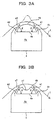
- This mini turn bar 4 has, for example, a cross section such as that shown in Figs. 2 and 3A and extends in the width direction of the web 1.
- the mini turn bar 4 is equipped with an internal space (flow passageway) 4a to which compressed air is supplied, a guide surface 4b disposed opposite the web 1, and nozzles 4c, 4d provided in the guide surface 4b.
- the nozzles 4c, 4d are used to squirt the compressed air within the interior space 4a toward the web 1.
- the mini turn bar 4 presses the web 1 toward the surface of the upper applicator roll 2 without contacting the web 1 by the compressed air squirted from the nozzles 4c, 4d. That is, the path of the web 1 is directed toward the upper applicator roll side by the mini turn bar 4.
- the web 1 contacts the surface of the upper applicator roll 2 a little longer, but since the angle ⁇ at which the web 1 is separated from the upper applicator roll 2 becomes greater, the position at which the web is separated becomes stable.
- the mini turn bar 4 by arranging the mini turn bar 4, the web 1 from the web-nipping portions 20 of the applicator rolls 2 travels while it is being held on the surface of the upper applicator roll 2. And at the position of the mini turn bar 4, the web 1 is forcibly separated toward the position of the turn bar 5. At this time, the mini turn bar 4 creates a layer of air between the web 1 and the guide surface 4b of the mini turn bar 4. Since this layer of air prevents the surface of the coatedweb 1 from contacting the mini turn bar 4, degradation in the quality of the coated web 1 is prevented.
- the guide surface 4b facing the web 1 is provided with nozzles 4c, 4d. Also, the surface 4b facing the web 1 is formed as an air-jet guide surface that has a smoothly curved cross section.
- the nozzles 4c, 4d are constructed as a great number of holes juxtaposed in the longitudinal direction of the mini turn bar 4, or they are constructed as two slits extending in the longitudinal direction, or they are constructed as a combination of such holes and slits.
- the nozzles 4c, 4d are provided on the front side (downstream side in the traveling direction of the web 1) and rear side (upstream in the traveling direction of the web 1) of the guide surface 4b, respectively.
- the nozzles 4c, 4d are constructed to squirt compressed air in the directions of arrows a1 and a2, respectively. This is for the purpose of creating a stable layer of air between the guide surface 4b and the web 1 and stably causing the path of the web 1 to be close to one of the two applicator rolls 2.
- the air-jet angle ⁇ of each of the nozzles 4c, 4d (i.e., the angle of the air- jet direction relative to the reference surface 4e of the mini turn bar 4) be within a predetermined range (e.g., a range of approximately 15 to 90 degrees).
- the air-jet angle ⁇ is too small (e.g., less than 15 degrees), the force of pressing the web 1 toward one of the two applicator rolls 2 is similarly weakened, it becomes difficult to cause the web 1 to move along a predetermined path, and there is a possibility that the web 1 will come into contact with the mini turn bar 4.
- the angle of the air-jet direction of each of the nozzles 4c, 4d relative to the reference surface 4e be within a predetermined range (e.g., a range of approximately 15 to 90 degrees).
- the radius R of curvature of the front surface (guide surface) 4b of the mini turn bar 4 within a predetermined range (e.g., a range of 20 to 400 mm). And it is also preferable to cause the web 1 to travel along a path curved so as to correspond to the radius R of curvature.
- an optimum value for the radius R of curvature of the guide surface 4b (which corresponds to the radius of the path of the web 1 at the position of the guide surface 4b) varies with the layout of a roll, drier, etc., and web tension.
- the optimum value also varies with the viscosity of a solution that is applied to the web 1 by the coater head 3. For example, when the viscosity of a solution is low and there is no need to separate the web 1 from the surface of the applicator roll 2 abruptly, the radius R of curvature may be great. However, when the viscosity of a solution is high and the web 1 needs to be separated from the surface of the applicator roll 2 abruptly, the radius R of curvature has to be small.
- the specification of the mini turn bar 4 such as the air-jet angle and air- jet strength of the nozzles 4c and 4d, etc. , in accordance with the viscosity of a solution to be applied to the web 1, web tension, and layout of each element.
- the guide surface 4b of the mini turn bar 4 f acing the web 1 may be provided with a concave static pressure pocket 4f.
- the jet of air can be effectively utilized for floating the web 1 off the mini turn bar 4. That is, the energy of air squirted from the nozzles 4c, 4d can be effectively converted into pressure that presses the web 1 toward one of the two applicator rolls 2.
- the application of a coating solution to the web 1 is performed in the following steps (method of applying a coating solution to the web 1, constructed in accordance with the first embodiment).
- the web 1 is fed into the coating apparatus from a previous step, and a coating solution is applied to each side of the web 1 at the web-nipping portions of the upper and lower applicator rolls 2. At this time, a film of coating solution is formed on each side of the web 1.
- the coated web 1 is conveyed to the turn bar 5 and drier 6.
- the web 1 first passes between the web-nipping portions 20. Then, the web 1 travels while it is being held on the surface of one (upper) of the two applicator rolls 2 by a predetermined circumferential length by the mini turn bar 4. Next, the web 1 is forcibly separated from the upper applicator roll 2 along the guide surface 4b of the mini turn bar 4.
- the path of the web 1 from the web-nipping portions 20 toward the turn bar 5 is forcibly pushed toward the surface of one (upper) of the two applicator rolls 2 so that the web 1 is brought into contact with the surface of the one applicator roll 2 for a long time and that the angle ⁇ at which the web 1 is separated from the surface of the one applicator roll 2 becomes great.
- the angle ⁇ at which the web 1 is separated is small, the web 1 is liable to vibrate at the position where the web is separated (see Fig. 15), and therefore theposition at which the web 1 is separatedbecomes unstable.
- the angle ⁇ at which the web 1 is separated is great, the web 1 is less liable to vibrate and therefore the position at which the web 1 is separated becomes stable.
- the separation angle ⁇ of the web 1 from the applicator roll 2 becomes greater by being guided along the mini turn bar 4, the separation position of the web 1 from the applicator roll 2 becomes stable and becomes constant in the width direction of the web 1, and the occurrence of a mist can be suppressed.
- coating unevenness such as that shown in Fig. 16, and a mist, which are found in prior art, can be prevented from occurring in the coated film on the web 1.
- mini turn bar 4 is of an air-flotation type, there is no possibility that the surface of the web 1 with a film of coating solution will make contact with the mini turn bar 4 and degrade the coating quality.
- the angle ⁇ of the air-jet direction of each of the nozzles 4c, 4d within a predetermined range (e.g., a range of approximately 15 to 90 degrees), the energy of an air jet can be efficiently utilized for floating the web 1 off the guide surface 4b and there is no possibility that the web 1 will bulge out at the central portion thereof (see the two-dot chain line in Fig. 3A).
- the path of the web 1 is reliably altered by the mini turn bar 4, so the separation position of the web 1 from the applicator roll 2 can be stabilized.
- the energy of a jet of air can be more efficiently converted into pressure that floats the web 1 off the guide surface 4b.
- the flotation of the web 1 by the mini turn bar 4 (toward one of two applicator rolls 2) can be reliably performed.
- the contact (contact distance) of the web 1 with one (upper) of the two applicator rolls 2 becomes longer, so coating conditions for both sides of the web 1 will differ. Because of this, as shown by reference numeral 1' and a two-dot chain line in Fig. 1, the angle at which the web 1 enters between the web-nipping portions 20 can be adjusted so that the contact of the web 1 with the other (lower) applicator roll 2 becomes longer. In this way, coating conditions for both sides of the web 1, particularly the capillary osmotic conditions of a coating solution into the web 1 (base paper) can be made equal. Also, the quantities of a coating solution that are applied to both sides of the web 1 can be balanced as the coating conditions required for each side of the web 1. In this case, the coating apparatus may further include a guide roll (paper roll) 7, which is arranged to the upstream side of the web-nipping portions 20 to adjust the angle at which the web 1 enters between the web-nipping portions 20.
- a guide roll paper roll
- Fig. 4 shows a simplified side view of a coating apparatus constructed in accordance with the second embodiment of the present invention.
- the same reference numerals as Fig. 1 denote the same parts and a description of these parts will be partly omitted.
- the coating apparatus of the second embodiment has the same mini turn bar 4 as the first embodiment to the downstream side of web-nipping portions 20.
- the coating apparatus further has the same guide roll (paper roll) 7 as the alteration of the first embodiment (see the two-dot chain line in Fig. 1) to the upstream side of the web-nipping portions 20.
- the mini turn bar 4 is arranged so that the web 1 is wound around a lower applicator roll 2.
- the paper roll 7 is arranged so that the web 1 is wound around an upper applicator roll 2.
- the mini turn bar 4 and paper roll 7 may be arranged in reverse order with respect to the upper and lower applicator rolls 2,2.
- a drier 6 and turn bar 5 are arranged to the downstream side of the applicator rolls 2,2 in the reverse order of the first embodiment. However, they are arranged properly in accordance with device-installation environment, etc.
- the mini turn bar 4 and paper roll 7 are provided with moving mechanisms (not shown), respectively. Because various moving mechanisms are well known in the prior art, a description of the detailed structures will not be given.
- the mini-turn-bar moving mechanism is used to properly move the mini turn bar 4 in a direction away from or toward the applicator roll 2 or circumferential direction of the applicator roll 2 or combined direction of these directions (e.g. , a direction from the position of reference numeral 4' in Fig. 4 to the position of reference numeral 4).
- a direction from the position of reference numeral 4' in Fig. 4 to the position of reference numeral 4 By moving the mini turn bar 4 in that direction, the contact length that the web 1 contacts one (lower) of the two applicator rolls 2 (i.e., the distance that the web 1 is held on the lower applicator roll 2) can be adjusted.
- the paper-roll moving mechanism is used to properly move the paper roll 7 in the required direction so that the angle at which the web 1 enters between the web-nipping portions 20 can be adjusted.
- the coating apparatus of the second embodiment of the present invention is constructed as described above, the same advantages as the first embodiment can be obtained by applying a coating solution to the web 1 with the coating apparatus.
- the position of the mini turn bar 4 is adjusted with the mini-turn-barmovingmechanism, whereby the contact length that the web 1 that contacts one (lower) of the two applicators 2 can be adjusted.
- the angle at which the web 1 enters between the web-nipping portions 20 is adjusted by adjusting the position of the paper roll 7 with the paper-roll moving mechanism, whereby the contact length that the web 1 contacts the other (upper) applicator roll 2 can be adjusted.
- the separation condition of the web 1 from one of the two applicator rolls 2 and coating conditions for both sides of the web 1 can be freely adjusted.
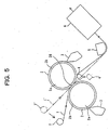
- Fig. 5 shows a simplified side view of a coating apparatus constructed in accordance with the third embodiment of the present invention.
- the same reference numerals as Figs. 1 and 4 denote the same parts and a description of these parts will be partly omitted.
- the coating apparatus of the third embodiment has the same mini turn bar 4 as the second embodiment to the downstream side of web-nipping portions 20.
- the coating apparatus further has the same guide roll (paper roll) 7 as the second embodiment to the upstream side of the web-nipping portions 20.
- the mini turn bar 4 is arranged so that the web 1 is wound around an upper applicator roll 2, and the paper roll 7 is arranged so that the web 1 is wound around a lower applicator roll 2.
- the mini turn bar 4 and paper roll 7 may be arranged in reverse order with respect to the upper and lower applicator rolls 2,2.
- a turn bar 5 and drier 6 are arranged to the downstream side of the applicator rolls 2,2 in the recited order, as with the first embodiment. However, they are arranged properly in accordance with device-installation environment, etc.
- the same mini turn bar 4 and paper roll 7 as those of the second embodiment are provided with moving mechanisms (not shown), respectively.
- the paper-roll moving mechanism is the same as that of the second embodiment.
- the mini-turn-bar moving mechanism is able to adjust the contact length that the web 1 contacts one (upper) of the two applicator rolls 2 (distance that the web 1 is held on one of the two applicator rolls) by moving the mini turn bar 4 in the diameter direction of the applicator roll 2.
- the mini-turn-bar moving mechanism is also able to move the mini turn bar 4 from the web 1 to the position indicated by reference numeral 4' in Fig. 4.
- the coating apparatus of the third embodiment of the present invention is constructed as described above, the same advantages as the second embodiment can be obtained by applying a coating solution to the web 1 with the coating apparatus.
- the mini turn bar 4 can be moved away from the path of the web 1, so working space can be ensured by moving the mini turn bar 4 away from the path of the web 1 during paper travel or maintenance of equipment.
- the advantage of enhancing operation efficiency is obtained.
- the paper-roll moving mechanism may also be constructed so that it can move the paper roll 7 away from the path of the web 1 to enhance operation efficiency.
- one of the two applicator rolls 2 (e.g., an upper application roll in Fig. 6) is constructed so that it is movable in a direction away from and toward the web 1 (vertical direction in Fig. 6) at a position where the center axis of the upper applicator roll 2 is offset horizontally from the center axis of the other applicator roll 2 (e.g., a lower application roll in Fig. 6).
- the web 1 can be wound around the lower applicator roll 2.
- a paper roll 7 and a paper-roll moving mechanism (not shown) to the side upstream of the applicator rolls 2.
- an air-flotation type mini turn bar 4 and a mini-turn-bar moving mechanism (not shown) to the downstream side of the applicator rolls 2. Therefore, the paper roll 7 is movable from reference numeral 7' to reference numeral 7 (see a arrow) and the mini turn bar 4 is movable from reference numeral 4' to reference numeral 4 (see an arrow).
- the embodiment shown in Fig. 6 further includes a downstream paper roll (fixed position) 7, which is mounted between the mini turn bar 4 and drier 6.
- the length that the web 1 is wound around one of the two applicator rolls 2 and the separation angle of the web 1 from the applicator roll 2 can be altered by adjusting the position of the applicator roll 2 and/or the position of the mini turn bar 4. Also, the length that the web 1 is wound around the other applicator roll 2 can be altered by adjusting the position of the upstream paper roll 7.
- mini turn bar air-flotation type mini turn bar
- the structure of the mini turn bar (air-flotation type mini turn bar) used in the coating apparatus of the present invention is not limited to the structure shown in Figs. 3A and 3B.
- Preferred examples are the structures of mini turn bars 30A, 30B, 30C, 30D, 30E, 30F, and 40 shown in Figs. 7 to 13.
- the mini turn bar 30A shown in Fig. 7 is a first preferred structure example.
- This mini turn bar 30A is equipped with a box-shaped main body 31 that has no cover. Compressed air from an air supply source (not shown) is supplied to the interior space 31a of the bar main body 31.
- the upper portions of the side walls 31b and 31c of the bar main body 31 diminish in width toward an opening, in which a U-shaped cover member 32 is arranged with its opening downward.
- an upstream gap slit-shaped groove.
- the upstream gap serves as the exit of a first air nozzle 35A that is formed by the side wall 31b of the bar main body 31 and the side wall 32b of the cover member 32.
- downstream gap serves as the exit of a second air nozzle 35B that is formed by the side wall 32c of the cover member 32 and the side wall 31c of the bar main body 31.
- partition members 34A, 34B in the form of a round bar are provided on the top surface 32a of the cover member 32 and extend in the width direction of the web 1.
- L-shaped plates 33A, 33B are attached to the exterior surface of the side walls 31b, 31c of the bar main body 31 and extend in the width direction of the web 1.
- a static pressure pocket (second air pocket) 36B is formed to the upstream side of the air nozzle 35A and is defined by the upstream L-shaped plate 33A and the side wall 31b of the bar main body 31.
- a static pressure pocket (third air pocket) 36C is formed to the downstream side of the air nozzle 35B and is defined by the downstream L-shaped plate 33B and the side wall 31C of the bar main body 31.
- the web 1 can be stably supported by both the dynamic pressure of compressed air that is squired out of the first and second air nozzles 35A, 35B and the static pressure of a layer of air within the first static pressure pocket 36A. Because the second and third static pressure pockets 36B, 36C are also provided at the inlet portion and outlet portion of the arcuately curved portion of the web 1, the flap of the web 1 against the mini turn bar 30A at the inlet and outlet portions can be suppressed by the static pressure of the air layers within the second and third static pressure pockets 36B, 36C. Thus, the web 1 can be prevented from contacting the mini turn bar 30A. As illustrated in Fig.
- the shape of the mini turn bar 30A which leads from the second static pressure pocket 36B on the inlet side to the third static pocket 36C on the outlet side, is symmetrically formed with respect to a center line L passing through the center of the first static pressure pocket 36A. Therefore, the web 1 is able to travel in a fixed radius of curvature and stable web travel becomes possible. Thus, according to the mini turn bar 30A, the web 1 is able to travel with a sufficient quantity of flotation and the problem of flaws in a coated surface due to contact can also be prevented.
- the slit width t of the exits of the air nozzles 35A, 35B is in a range of 0.5 to 5.0 mm and the diameter ⁇ of the partition members 34A, 34B in a range of 1 to 10 mm.
- the radius R of curvature of the web 1 is determined by the shape of the mini turn bar 30A, and as the radius R of curvature becomes smaller, the reaction force that the mini turn bar 30A undergoes from the web 1 through a layer of air becomes greater. Since the mini turn bar 30A has a long and narrow structure extending in the width direction of the web 1, it is preferable that the radius R of curvature be 100 mm or greater, if rigidity is taken into consideration.
- the mini turn bar 30B shown in Fig. 8 is a second preferred structure example.
- This mini turn bar 30B is an alteration of the first mini turn bar 30A.
- the side walls 31b, 31c of the bar main body 31 of the second mini turn bar 30B are partly different from the first mini turn bar 30A. That is, the upper portions of the side walls 31b, 31c of the bar main body 31, as with first example, diminish in width toward an opening, but the upper ends are vertically formed and are parallel to the side walls 32b, 32c of a cover member 32.
- the air-jet directions of air nozzles 35A, 35B in the second example are approximately parallel to a center line L, and as illustrated in Fig. 8, a second static pressure pocket 36B and third static pressure pocket 36C at the inlet and outlet portions can be made deeper than the first example.
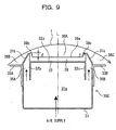
- the mini turn bar 30C shown in Fig. 9 is a third preferred structure example. While the first mini turn bar 30A forms the static pressure pocket 36A by installing the partition members 34A, 34B in the shape of a bar on the top surface 32a of the cover member 32, the mini turn bar 30C of the third example is characterized in that a static pressure pocket 36A is formed by mounting a U-shaped plate 38 with left and right side walls 38b, 38c on the top surface 32a of a cover member 32.
- the U-shaped plate 38 is formed from a thick member, and the upper round corners of the left and right side walls 38b, 38c has a radius r of curvature, as shown in Fig. 9.
- the mini turn bar 30D shown in Fig. 10 is a fourth preferred structure example.
- This mini turn bar 30D is an alteration of the third mini turn bar 30C, and the upper portions of the side walls 31b, 31c of a bar main body 31 are formed the same as the second example.
- the height d of the side walls 38b, 38c of the U-shaped plate 38 (pocket depth d) is 1 to 20 mm
- the difference h in height between the side walls 38b, 38c of the U-shaped plate 38 and the side walls 31b, 31c of the bar main body 31 is -5 to 3 mm
- the radius r of curvature of the side walls 38b, 38c of the U-shaped plate 38 is 0.5 to 5 mm.
- the upper ends of the side walls 38b, 38c of the U-shaped plate 38 may be chamfered instead of being rounded.
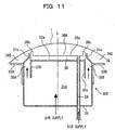
- the mini turn bar 30E shown in Fig. 11 is a fifth preferred structure example.
- This mini turn bar 30E is an alteration of the fourth mini turn bar 30D, and within a static pressure pocket 36A, there is provided an air nozzle (third air nozzle) 39 from which compressed air is squirted.
- the air nozzle 39 has an opening in the top surface of a U-shaped plate 38 and is connected to an air supply source (not shown).
- the air supply source to which the third air nozzle 39 is connected may be the same system as an air supply source to which first and second air nozzles 35A, 35B are connected, oradifferent system.
- the air supply system is constructed so that the third air nozzle 39 can squirt compressed air higher in pressure than the first and second air nozzles 35A, 35B.
- the above-described mini turn bar 30E has the following advantages. That is, as the web 1 travels near the mini turn bar 30E, the air within the central static pressure pocket 36A passes over the side wall 38c of the U-shapedplate 38 that is the partitionwall portion between the static pressure pockets 36A and 36C, and flows into the downstream static pressure pocket 36C. At this partition wall portion the web 1 is supported by the pressure of the wake air, but the flow passage area of the wake air at that partition wall portion widens gradually from the center static-pressure pocket 36A toward the downstream static-pressure pocket 36C, as shown in Fig. 11. Therefore, the dynamic pressure component of the wake air at the partition wall portion is gradually reduced as the flow passage area enlarges.
- the web 1 will contact the partition wall portion.
- the static pressure component of the wake air flowing out from the static-pressure pocket 36A is enhanced by compressed air squirted from the air nozzle 39, so a compensation for a reduction in the dynamic pressure can be made and contact between the web 1 and the partition wall portion can be prevented.
- the mini turn bar 30F shown in Figs. 12A and 12B is a sixth preferred structure example.
- This mini turn bar 30F is an alteration of the fourth mini turn bar 30D and is characterized in that there is provided a labyrinth structure in each of the static pressure pockets 36A, 36B, and 36C. That is, as shown in Figs. 12A and 12B, the static pressure pockets 36A, 36B, and 36C are provided with a plurality of baffle plates (partition wall) 37A, 37B, and 37C, which are arranged at predetermined intervals in the longitudinal direction of the mini turn bar 30F (width direction of the web 1).
- the baffle plates 37A, 37B, and 37C segment each of the static pressure pockets 36A, 36B, and 36C into a plurality of sections.
- the baffle plates 37A, 37B, and 37C give strong resistance to air flowing between the web 1 and the mini turn bar 30F. That is, the baffle plates 37A, 37B, and 37C form a sort of labyrinth structure between the web 1 and the mini turn bar 30F.
- the labyrinth structure converts the kinetic energy of air into pressure, so the static pressure within each of the static pressure pockets 36A, 36B, and 36C rises.
- the mini turn bar 30F is capable of supporting the web 1 more stably by such a labyrinth structure and preventing the web 1 from vibrating and making a noise.
- each of the static pressure pockets 36A, 36B, and 36C is provided with a labyrinth structure, all the static pressure pockets 36A, 36B, and 36C does not always need to have a labyrinth structure. For instance, even when only the center static pressure pocket 36A has a labyrinth structure, the above-described advantages are obtained.
- the mini turn bar 40 shown in Fig. 13 is a seventh preferred structure example.
- This mini turn bar 40 is equipped with a box-shaped main body 41 having no cover, and compressed air from an air supply source (not shown) is supplied to the interior space 41a of the bar main body 41.
- a U-shaped cover member 42 is arranged with its opening downward.
- passages 45A, 45B are formed between the side walls 41b, 41c of the bar main body 41 and the side walls 42b, 42c of the cover member 42, there are formed passages 45A, 45B, which are in communication with the interior space 41a.
- These passages 45A, 45B serve as air nozzles that squirt compressed air out of the interior space 41a. They will hereinafter be referred to as air nozzles.
- L-shaped flange members 48A, 48B are attached to the interior surface of the side walls 41b, 41c of the bar main body 41, and between the upper ends of the flange members 48A, 48B and the lower ends of the side walls 42b, 42c of the cover member 42, the inlet portions of the first and second air nozzles 45A, 45B into which compressed air flows from the interior space 41a are narrowed down.
- U-shapedpartitionmembers 44A, 44B are arranged left and right on the top surface 42a of the cover member 42 with their openings downward.
- the lower ends of the inner side walls 44Ab, 44Bb of the partition members 44A, 44B are mounted on the top surface 42a of the cover member 42, and between the lower ends of the outer side walls 44Ac, 44Bc and the top surface 42a of the cover member 42, there are formed gaps through which the interiors of the partition members 44A, 44B communicate with the air nozzles 45A, 45B.
- the side walls 41b, 41c of the bar main body 41 extend near the top surfaces 44Aa, 44Ba of the partition members 44A, 44B, and between the upper end portions of the side walls 41b, 41c of the bar main body 41 and the partition members 44A, 44B, there are formed slit-shaped grooves 451B and 451C extending in the width direction of the web 1.
- the top surfaces 44Aa, 44Ba of the partition members 44A, 44B are formed into curved surfaces, which correspond to the curved path of the web 1.
- the curved tope surfaces 44Aa, 44Ba have a great number of bores 452 arranged evenly in zigzags.
- the grooves 451B, 451C and bores 452 form the exits of the air nozzles 45A, 45B.
- the grooves 451B, 451C will hereinafter be referred to as air-jet grooves and the bores 452 will hereinafter be referred to as air-jet bores.
- the top surfaces 44Aa, 44Ba of the partition members 44A, 44B in which the air-jet bores 452 are formed will hereinafter be referred to as air-jet surfaces.
- the above-described partition members 44A, 44B form a static pressure pocket (first air pocket) 46A along with the top surface 42a of the cover member 42.
- a reinforcement plate 47 through which both partition members 44A and 44B are connected.
- L-shaped plates 43A, 43B are attached to the exterior surfaces of both side walls 41b, 41c of the bar main body 41 and extend in the width direction of the web 1.
- a static pressure pocket (second air pocket) 46B which is defined by the upstream L-shaped plate 43A and the side wall 41b of the bar main bar 41, is formed to the downstream side of the air nozzle 45A.
- a static pressure pocket (third air pocket) 46C which is defined by the downstream L-shaped plate 43B and the side wall 41C of the bar main bar 41, is formed to the upstream side of the air nozzle 45B.
- the web 1 can be stably supported by both the dynamic pressure of the compressed air squired from the air nozzles 45A, 45B and the static pressure of the layer of air within the static pressure pocket 46A formed on the top surface 42a of the cover member 42.
- the static pressure pockets 46B, 46C are provided at the inlet and outlet portions of the curved portion of the web 1, so the flap of the web 1 against the mini turn bar 40 at the inlet and outlet portions can be suppressed by the static pressure of the air layers formed within the static pressure pockets 46B, 46C, and the contact of the web 1 with the mini turn bar 40 can be prevented.
- the air within the central static pressure pocket 46A passes over the partition member 44B that is the partition wall portion between the static pressure pockets 46A and46C, and flows into the downstream static pressure pocket 46C.
- the web 1 is supported by the pressure of the wake air, but the flow passage area of the wake air widens gradually from that partition wall portion toward the downstream static-pressure pocket 46C. Therefore, the dynamic pressure component of the wake air at the partition wall portion is gradually reduced as the flow passage area enlarges.
- the top surface 44Ba of the partition member 44B that is the partition wall portion is used as the air-jet surface, so contact between the web 1 and the partition member 44B can be prevented by a layer of compressed air that is squired out of the air-jet surface 44Ba.
- a curtain of compressed air from the air-jet groove 451B can prevent the air squirted out of the air-jet surface 44Ba from leaking out as the web 1 travels, and a layer of air can be reliably formed between the web 1 and partition member 44B.
- the shape of the mini turn bar 40 which leads from the upstream static pressure pocket 46B to the downstream static pocket 46C, is symmetrically formed with respect to a center line L passing through the center of the center static pressure pocket 46A, so the web 1 is able to travel in a fixed radius of curvature and stable travel of the web 1 becomes possible.
- the web 1 is able to travel stably with a sufficient quantity of flotation without contacting the mini turn bar. Therefore, if a coating solution is applied to the web 1 by the coating apparatus equipped with the mini turn bar 30A, 30B, 30C, 30D, 30E, 30F, or 40, the quality of the coated paper can be further enhanced.
- the respective characteristic constructions of the mini turn bars 30A, 30B, 30C, 30D, 30E, 30F, and 40 can be combined together.
- the labyrinth structure of the six mini turn bar 30F can be provided in the other mini turn bars 30A, 30B, 30C, 30D, 30E, and 40.
- the third air nozzle 39 of the fifth mini turn bar 30E can also be provided in the other mini turn bars 30A, 30B, 30C, 30D, 30F, and 40.
Landscapes
- Coating Apparatus (AREA)
- Application Of Or Painting With Fluid Materials (AREA)
- Registering, Tensioning, Guiding Webs, And Rollers Therefor (AREA)
- Nozzles (AREA)
Abstract
In an apparatus for applying a film of coating
solution to each side of a web such as paper, resin film,
etc., there is provided an air-flotation type mini turn
bar (4) to the downstream side of the nipping portions
(20) of two applicator rolls (2,2). The air-flotation
type mini turn bar (4) is used to convey the web (1) while
holding the web on the surface of one of the two applicator
rolls (2), after it passes between the nipping portions
(20). In this way, the occurrence of flaws in the coated
surfaces of the web (1) is prevented, the occurrence of
a mist and coating unevenness is suppressed, and a film
of coating solution is formed evenly on each side of the
web.
Description
The present invention relates to an apparatus
and method, which are used in paper-making machines,
resin-film manufacturing machines, etc., for applying a
coating solution to the surface of a web such as paper,
resin film, etc., and also relates to an air-flotation
type mini turn bar that is suitably used in the coating
apparatus.
In paper-making machines, resin-film
manufacturing machines, etc., there is provided an
apparatus for applying a coating solution to the surface
of a web such as paper, resin film, etc.
Fig. 14 is a simplified side view showing a
conventional coating apparatus. As illustrated in the
figure, a web 1, such as paper, etc., is fed from a previous
step and passes between the web-nipping portions 20 of
two applicator rolls 2 which are formed when they are pressed
against each other. After the web 1 is coated with a coating
solution, it goes into a drier 6 via a turn bar
(air-flotation/non-contact type web-travel supporting
unit) 5 that conveys the web 1 while floating it.
The application of a coating solution to both
sides of the web 1 is performed as follows:
Each applicator roll 2 includes a main body 2a
made of metal such as steel, etc. The roll main body 2a
has an elastic film 2b such as a film of rubber on the
outer periphery. Each applicator roll 2 rotates at the
same circumferential speed as the travel speed of the web
1. The applicator roll 2 is equipped with a coater head
3, which is a means of supplying a coating solution to
the surface of the elastic film 2b.
The coater head 3 contains measurement means
such as a coating solution supply passage, measuring rod,
blade, etc. After a sufficient quantity of coating
solution is supplied from the coater head 3 to the surface
of the applicator roll 2, at the exist of the coater head
the measuring rod is pressed against the surface of the
applicator roll 2 to form a film of coating solution with
a predetermined thickness on the surface of the applicator
roll 2.
Note that the film thickness of the coating
solution on the applicator roll 2 is adjusted by controlling
the force of pressing the measuring rod or blade against
the applicator roll 2. The technique of forming a film
of coating solution on the applicator roll 2, described
above, is well known in the prior art (see, for example,
Y. Miura, "Trend of the Latest Coater-Size Press
Technique," Paper-Pulp Technique Times, No. 12, 1997) and
is not particularly limited.
A film of coating solution formed on each of
the applicator rolls 2 by the above-described technique
is transferred and applied to each side of the web 1 as
it passes between the web-nipping portions 20 of the
applicator rolls 2 which are formed when they are pressed
against each other.
The web 1 with a film of coating solution
transferred and applied to each side is conveyed to a drier
6. At this time, as shown in Fig. 14, if the coating solution,
transferred and applied from the applicator rolls 2 to
the web 1, is in an undried state and contacts a solid
object such as a conveyance roll during conveyance, the
coated surface will be flawed and the quality will be
considerably degraded. Because of this, in the web
conveyance between the web-nipping portions 20 of the
applicator rolls 2 and drier 6, there is used an air floater,
or a turn bar 5 called a non-contact type guide member.
The non-contact type guide member 5 is used to
support and convey the web 1 without contacting the web
surface by floating the web 1 with the force of air.
Therefore, the web 1 can be conveyed to the drier 6 without
degrading the quality of the coated surface in an undried
state, formed on the surface of the web 1.
Now, a description will be given of problems
found in the above-described conventional technique.
In the case where the web 1 is paper that absorbs
water, water absorption sometimes causes elongation and
shrinkage of the web 1, if a coating solution is transferred
and applied to the web 1. Also, in the case where the
web 1 is resin film, etc., and is elongated or shrunk by
the temperature of a coating solution, elongation and
shrinkage sometimes occurs in the web1, if a film of coating
solution is transferred and applied to each side of the
web 1 at the web-nipping portions 20 of the applicator
rolls 2.
On the other hand, the above-described
conventional technique, as shown in Fig. 14, does not have
any device that regulates the path of the web 1 between
the web-nipping portions 20 of the applicator rolls 2 and
the turn bar 5.
Therefore, in the case where there occurs
elongation and shrinkage in the web 1, and the web 1 is
elongated particularly at the exist of the web-nipping
portions 20, the web 1 sometimes travels while sticking
to the surface of one of the upper and lower applicator
rolls 2 because of the stickiness of a coating solution,
as shown in Fig. 15.
When the web 1 is wide (in the width direction
of the applicator roll 2), the state of sticking becomes
uneven in the width direction of the web 1. That is, one
portion of the web 1 in the web width direction sticks.
to the upper applicator roll 2, while another portion sticks
to the lower applicator roll 2. Therefore, there are cases
where the web 1 vibrates between the surfaces of the upper
and lower applicator rolls 2.
In the case where coating operations are
performed at high speeds, there are cases where the state
of uneven sticking starts to fluctuate temporally and
becomes unstable. This phenomenon is disclosed, for
example, in Japanese Laid-Open Patent Publication No.
HEI 7-163924.
When the position and angle at which the web
1 is separated from the applicator roll 2 are uneven and
unstable, there are cases where coating unevenness, called
peeling patterns such as that shown by reference numeral
11 in Fig. 16, take places in the coated film on the web
1. This phenomenon is, for example, the same as that shown
in Figs. 4 and 8 of Japanese Patent No. 2578183.
The above-described phenomenon is considered
to take place for the following reasons: when the coating
solution between the surface of the web 1 and the surface
of the applicator roll 2 is split between the applicator
roll side and the web surface side after the web 1 passes
between the web-nipping portions of the applicator rolls
2, the meniscus of the split solution becomes unstable;
as a result, the transfer rate of the coating solution
that is transferred from the applicator roll 2 to the web
surface becomes temporally and spatially unstable; and
the film thickness of the coating solution formed on the
web surface becomes uneven.
In addition to the peeling patterns, there is
a fear of a misting phenomenon occurring. That is, in
the case of high-speed coating operations, a coating
solution scatters in drops because of the above-described
meniscus unstableness. If this phenomenon takes place,
the coating apparatus and coated paper will be stained
with a coating solution and there will be a possibility
of operations being suspended.
The present invention has been made in view of
the circumstances described above. Accordingly, it is
the object of the present invention to provide a coating
apparatus and coating method which are capable of evenly
forming a film of coating solution on each side of a web
by suppressing the occurrence of a mist and coating
unevenness, while preventing the occurrence of flaws in
the coated surfaces.
To achieve this end, there is provided an
apparatus that transfers and applies a film of coating
solution on each of two applicator rolls to each side of
a web as it passes between web-nipping portions of the
two applicator rolls which are formed when they are pressed
against each other. The apparatus includes an
air-flotation type mini turn bar, which is provided to
the downstream side of the web-nipping portions. The
air-flotation type mini turn bar is used to convey the
web while holding the web on the surface of one of the
two applicator rolls, after the web passes between the
web-nipping portions.
According to the coating apparatus of the
present invention, the air-flotation type mini turn bar
is able to convey the web while holding the web on the
surface of one of the two applicator rolls, after the web
passes between the web-nipping portions. By forcibly
holding the web on the surface of one of the two applicator
rolls, the position at which the web is separated from
the applicator roll becomes stable. For instance, the
occurrence of coating unevenness called peeling patterns
can be prevented, and consequently, coating quality can
be considerably enhanced.
Preferably, the coating apparatus of the present
invention further includes a mechanism that moves the mini
turn bar. Preferably, the mini-turn-bar moving mechanism
is constructed to adjust the distance that the wed is held
on one of the two applicator rolls, or adjust the distance
between the one applicator roll and the mini turn bar.
By providing the mini-turn-bar moving mechanism, the
separation of the web from one of the two applicator rolls
and the application of a coating solution from the one
applicator roll to the web can be adjusted.
Preferably, the coating apparatus of the present
invention further includes a paper roll, which is provided
to the upstream side of the web-nipping portions. The
paper roll is used to convey the web while holding the
web on the surface of the other of the two applicator rolls,
before the web passes between the web-nipping portions.
By providing the paper roll, the application of a coating
solution from the other applicator roll to the web can
be suitably adjusted.
In this case, the coating apparatus of the
present invention preferably includes a mechanism that
moves the paper roll. By providing the paper-roll moving
mechanism (position adjustment mechanism), the
application of a coating solution from the other applicator
roll to the web can be suitably adjusted.
In accordance with the present invention, there
is provided an air-flotation type mini turn bar that causes
a web to travel so as to form an arcuately curved portion
around the bar by floating the web with air. The
air-flotation type mini turn bar includes a first air pocket
arranged inside the arcuately curved portion of the web;
a second air pocket provided adjacent to the first air
pocket and arranged near an entrance portion of the curved
portion; a third air pocket provided adjacent to the first
air pocket and arranged near an exit portion of the curved
portion; a first air nozzle provided between the first
air pocket and the second air pocket for squirting air
toward the web; and a second air nozzle provided between
the first air pocket and the third air pocket for squirting
air toward the web.
According to the above-described air-flotation
type mini turn bar, the bottom surface of the curved portion
of the web can be stably supported by both the dynamic
pressure of air squired from each of the air nozzles and
the static pressure of air within each of the air pockets,
and the web is able to travel so as to form an arcuately
curved portion around the mini turn bar without being
contacted by the mini turn bar. Therefore, in the case
where the web is coated paper, there is no possibility
that the coated surfaces of the web will contact the mini
turn bar, and the problem of flaws in coated surfaces can
be prevented.
Preferably, the air-flotation type mini turn
bar further includes a third air nozzle that squirts
higher-pressure air than atmospheric pressure into the
first air pocket. According to the third air nozzle, the
static pressure within the first air pocket is made higher.
This can compensate for a reduction in the dynamic pressure
component of the wake air in the partition wall portion
between air pockets, particularly the first air pocket
and third air pocket. Therefore, the web and partition
wall portion can be prevented from contacting each other
because of negative pressure.
Preferably, a shape from the second air pocket
to the third air pocket is formed symmetrically with respect
to the center line of the first air pocket. According
to this shape, the web can travel along a path having a
fixed radius of curvature and stable web travel becomes
possible.
Furthermore, the air-flotation type mini turn
bar preferably adopts a labyrinth structure. That is,
the air-flotation type mini turn bar further includes a
plurality of first baffle walls, which are provided in
the direction of the width of the web within the first
air pocket so that the first air pocket is segmented into
a plurality of sections. Also, the air-flotation type
mini turn bar includes a plurality of second baffle walls
and a plurality of third baffle walls. The second baffle
walls are provided in the direction of the width of the
web within the second air pocket so that the second air
pocket is segmented into a plurality of sections. The
third baffle walls are provided in the direction of the
width of the web within the third air pocket so that the
third air pocket is segmented into a plurality of sections.
According to this labyrinth structure, the web can be
supported by the static pressure within each section.
Therefore, even when the web shifts in the width direction,
a fluctuation in the supporting pressure is slight. Also,
since each baffle wall is resistant to the wake air, the
interior static pressure becomes higher. Therefore,
according to such a labyrinth structure, the web can be
more stably supported and the web can be prevented from
vibrating and making a noise.
Preferably, the second air nozzle includes a
second air-jet surface and a second slit-shaped air-jet
groove, which are provided on a third surface extending
in the direction of the width of the web. The second air-jet
surface has a great number of air- jet bores and is provided
near the first air pocket. The second air-jet groove
extends in the direction of the width of the web and is
provided near the third air pocket.
The structure of the second air nozzle can
reliably prevent contact of the web at the baffle wall
portion between the first air pocket and third air pocket
where contact with the web is liable to occur because of
a reduction in the dynamic pressure component of the wake
air. Preferably, the first air nozzle has the same
structure as the second air nozzle. That is, the first
air nozzle includes a first air-jet surface and a first
slit-shaped air- jet groove, which are provided on the third
surface extending in the direction of the width of the
web. The first air-jet surface has a great number of
air-jet bores and is provided near the first air pocket.
The first air-jet groove extends in the direction of the
width of the web and is provided near the second air pocket.
The present invention will be described in
further detail with reference to the accompanying drawings
wherein:
Embodiments of the present invention will
hereinafter be described with reference to the drawings.
First, a first embodiment of the present
invention will be described in conjunction with the
drawings.
As illustrated in Fig. 1, a coating apparatus
is equipped with two applicator rolls 2, 2, which are
arranged opposite each other so as to form web-nipping
portions 20 when they are pressed against each other. A
film of coating solution, supplied to each of the applicator
rolls 2,2 by a coater head 3, is transferred and applied
to each side of a web 1 as it passes between the web-nipping
portions 20. The coated web 1 is guided without being
contacted by a turn bar (air-flotation/non-contact type
web-travel supporting unit) 5 and goes into a drier 6.
Each applicator roll 2, as with the above-described
conventional applicator roll, includes a main body 2a made
of metal such as steel, etc. The roll main body 2a has
an elastic film 2b such as a film of rubber on the outer
periphery.
The coating apparatus, as illustrated in Figs.
1 and 2, further includes an air-flotation type mini turn
bar 4 (which is an air-flotation/non-contact type
web-travel support unit and smaller in size than the turn
bar 5, and which will hereinafter be referred to simply
as a mini turn bar). The mini turn bar 4 functions as
a web-separating unit and is arranged in close proximity
to a portion of one of the two applicator rolls 2 (e.g.,
the upper applicator roll 2 in the first embodiment) which
is downstream from the web-nipping portion 20. The mini
turn bar 4 is used to convey the web 1 while holding it
on the surface of the upper applicator roll 2. In this
way, the position at which the web 1 with a filin of coating
solution is separated from the upper applicator roll 2
is stabilized, and the web-separating position is kept
constant in the direction of the width of the web 1.
This mini turn bar 4 has, for example, a cross
section such as that shown in Figs. 2 and 3A and extends
in the width direction of the web 1. The mini turn bar
4 is equipped with an internal space (flow passageway)
4a to which compressed air is supplied, a guide surface
4b disposed opposite the web 1, and nozzles 4c, 4d provided
in the guide surface 4b. The nozzles 4c, 4d are used to
squirt the compressed air within the interior space 4a
toward the web 1.
With this arrangement, the mini turn bar 4
presses the web 1 toward the surface of the upper applicator
roll 2 without contacting the web 1 by the compressed air
squirted from the nozzles 4c, 4d. That is, the path of
the web 1 is directed toward the upper applicator roll
side by the mini turn bar 4.
As a result, the web 1 contacts the surface of
the upper applicator roll 2 a little longer, but since
the angle α at which the web 1 is separated from the upper
applicator roll 2 becomes greater, the position at which
the web is separated becomes stable.
That is, as shown in Figs. 1 and 2, by arranging
the mini turn bar 4, the web 1 from the web-nipping portions
20 of the applicator rolls 2 travels while it is being
held on the surface of the upper applicator roll 2. And
at the position of the mini turn bar 4, the web 1 is forcibly
separated toward the position of the turn bar 5. At this
time, the mini turn bar 4 creates a layer of air between
the web 1 and the guide surface 4b of the mini turn bar
4. Since this layer of air prevents the surface of the
coatedweb 1 from contacting the mini turn bar 4, degradation
in the quality of the coated web 1 is prevented.
To create a layer of air between the guide surface
4b of the mini turn bar 4 and the web 1, the guide surface
4b facing the web 1 is provided with nozzles 4c, 4d. Also,
the surface 4b facing the web 1 is formed as an air-jet
guide surface that has a smoothly curved cross section.
The nozzles 4c, 4d are constructed as a great
number of holes juxtaposed in the longitudinal direction
of the mini turn bar 4, or they are constructed as two
slits extending in the longitudinal direction, or they
are constructed as a combination of such holes and slits.
Also, in the first embodiment, the nozzles 4c,
4d are provided on the front side (downstream side in the
traveling direction of the web 1) and rear side (upstream
in the traveling direction of the web 1) of the guide surface
4b, respectively. The nozzles 4c, 4d are constructed to
squirt compressed air in the directions of arrows a1 and
a2, respectively. This is for the purpose of creating
a stable layer of air between the guide surface 4b and
the web 1 and stably causing the path of the web 1 to be
close to one of the two applicator rolls 2.
To stably cause the path of the web 1 to be close
to one of the two applicator rolls 2, it is effective not
only to squirt compressed air toward the web 1, but also
to create a stable layer of air between the web guide surface
4b and the web 1 so that air is stored between the web
guide surface 4b and the web 1. If both nozzles 4c, 4d
are actuated, air is stored between the guide surface 4b
and the web 1 and a stable layer of air can be created
between the guide surface 4b and the web 1. Hence, the
nozzles 4c, 4d are formed in the front and rear portions
of the guide surface 4b, respectively.
To effectively utilize the energy of the
squirted air for floating the web 1 off the guide surface
4b, it is preferable that the air-jet angle of each of
the nozzles 4c, 4d (i.e., the angle of the air- jet direction
relative to the reference surface 4e of the mini turn bar
4) be within a predetermined range (e.g., a range of
approximately 15 to 90 degrees).
That is, if the air-jet angle becomes 90
degrees or greater, the greater part of a flow of air from
each of the nozzles 4c, 4d will flow out of the front and
rear portions of the guide surface 4b. As a result, the
force acting on the web 1 is greatly reduced, the force
of pressing the web 1 toward the upper applicator roll
2 becomes weak, and it becomes difficult to cause the web
1 to move along a predetermined path.
On the other hand, if the air-jet angle is
too small (e.g., less than 15 degrees), the force of pressing
the web 1 toward one of the two applicator rolls 2 is
similarly weakened, it becomes difficult to cause the web
1 to move along a predetermined path, and there is a
possibility that the web 1 will come into contact with
the mini turn bar 4.
Note that even if the air-jet force that acts
on the web 1 is weak, it is possible to cause the web 1
to move along a predetermined path by lowering web tension.
However, in this case, as shown by a two-dot chain line
in Fig. 3A, the web 1 bulges out in the vicinity of the
central portion of the guide surface 4b, and consequently,
the web 1 cannot travel smoothly. Therefore, web tension
cannot be lowered greatly, and if the air- jet force acting
on the web 1 is weak, it is fairly difficult to cause the
web 1 to move along a predetermined path.
Thus, it is preferable that the angle of the
air-jet direction of each of the nozzles 4c, 4d relative
to the reference surface 4e be within a predetermined range
(e.g., a range of approximately 15 to 90 degrees).
Also, for the position at which the web 1 is
separated from the surface of the upper applicator roll
2 to be stable and constant in the width direction of the
web 1, it is preferable to set the radius R of curvature
of the front surface (guide surface) 4b of the mini turn
bar 4 within a predetermined range (e.g., a range of 20
to 400 mm). And it is also preferable to cause the web
1 to travel along a path curved so as to correspond to
the radius R of curvature.
Note that an optimum value for the radius R of
curvature of the guide surface 4b (which corresponds to
the radius of the path of the web 1 at the position of
the guide surface 4b) varies with the layout of a roll,
drier, etc., and web tension. The optimum value also
varies with the viscosity of a solution that is applied
to the web 1 by the coater head 3. For example, when the
viscosity of a solution is low and there is no need to
separate the web 1 from the surface of the applicator roll
2 abruptly, the radius R of curvature may be great. However,
when the viscosity of a solution is high and the web 1
needs to be separated from the surface of the applicator
roll 2 abruptly, the radius R of curvature has to be small.
In addition to the radius R of curvature of the
guide surface 4b, it is preferable to optimally set the
specification of the mini turn bar 4, such as the air-jet
angle and air- jet strength of the nozzles 4c and 4d, etc. ,
in accordance with the viscosity of a solution to be applied
to the web 1, web tension, and layout of each element.
Note that there is a relation of P = T/R between
the radius R of curvature, the tension T of the web 1,
and the pressure P applied to the web 1 by the nozzles
4c, 4d. The radius R of curvature, web tension T, and
pressure P (air-jet angle and air-jet strength of the
nozzles 4c, 4d) are set so as to meet the above-described
relation.
As shown in Fig. 3B, the guide surface 4b of
the mini turn bar 4 f acing the web 1 may be provided with
a concave static pressure pocket 4f. By reliably holding
a jet of air on the guide surface 4b by the static pressure
pocket 4f, the jet of air can be effectively utilized for
floating the web 1 off the mini turn bar 4. That is, the
energy of air squirted from the nozzles 4c, 4d can be
effectively converted into pressure that presses the web
1 toward one of the two applicator rolls 2.
Since the coating apparatus of the first
embodiment of the present invention is constructed as
described above, the application of a coating solution
to the web 1 is performed in the following steps (method
of applying a coating solution to the web 1, constructed
in accordance with the first embodiment).
That is, the web 1 is fed into the coating
apparatus from a previous step, and a coating solution
is applied to each side of the web 1 at the web-nipping
portions of the upper and lower applicator rolls 2. At
this time, a film of coating solution is formed on each
side of the web 1. The coated web 1 is conveyed to the
turn bar 5 and drier 6.
In the coating apparatus and method of the first
embodiment, the web 1 first passes between the web-nipping
portions 20. Then, the web 1 travels while it is being
held on the surface of one (upper) of the two applicator
rolls 2 by a predetermined circumferential length by the
mini turn bar 4. Next, the web 1 is forcibly separated
from the upper applicator roll 2 along the guide surface
4b of the mini turn bar 4.
That is, by air squirted from the nozzles 4c,
4d of the mini turn bar 4, the path of the web 1 from the
web-nipping portions 20 toward the turn bar 5 is forcibly
pushed toward the surface of one (upper) of the two
applicator rolls 2 so that the web 1 is brought into contact
with the surface of the one applicator roll 2 for a long
time and that the angle α at which the web 1 is separated
from the surface of the one applicator roll 2 becomes great.
Generally, if the angle α at which the web 1 is separated
is small, the web 1 is liable to vibrate at the position
where the web is separated (see Fig. 15), and therefore
theposition at which the web 1 is separatedbecomes unstable.
Conversely, if the angle α at which the web 1 is separated
is great, the web 1 is less liable to vibrate and therefore
the position at which the web 1 is separated becomes stable.
Further, since the position at which the web
1 is separated becomes stable, a meniscus, which is formed
as afilm of coating solution is split between the applicator
roll side and the web surface side, becomes stable and
the occurrence of a mist can be suppressed.
Thus, in the coating apparatus of the first
embodiment, the separation angle α of the web 1 from the
applicator roll 2 becomes greater by being guided along
the mini turn bar 4, the separation position of the web
1 from the applicator roll 2 becomes stable and becomes
constant in the width direction of the web 1, and the
occurrence of a mist can be suppressed.
Hence, coating unevenness, called peeling
patterns such as that shown in Fig. 16, and a mist, which
are found in prior art, can be prevented from occurring
in the coated film on the web 1.
Of course, because the mini turn bar 4 is of
an air-flotation type, there is no possibility that the
surface of the web 1 with a film of coating solution will
make contact with the mini turn bar 4 and degrade the coating
quality.
Thus, the occurrence of coating unevenness and
a mist in the web 1 can be prevented, while preventing
the occurrence of a flaw in the coated surfaces of the
web 1. Therefore, the formation of an even film of coating
solution becomes possible and the coating quality and
operating environment are greatly enhanced.
Also, by setting the angle of the air-jet
direction of each of the nozzles 4c, 4d within a
predetermined range (e.g., a range of approximately 15
to 90 degrees), the energy of an air jet can be efficiently
utilized for floating the web 1 off the guide surface 4b
and there is no possibility that the web 1 will bulge out
at the central portion thereof (see the two-dot chain line
in Fig. 3A). The path of the web 1 is reliably altered
by the mini turn bar 4, so the separation position of the
web 1 from the applicator roll 2 can be stabilized.
As shown in Fig. 3B, if the guide surface 4b
of the mini turn bar 4 is provided with the static pressure
pocket 4f, the energy of a jet of air can be more efficiently
converted into pressure that floats the web 1 off the guide
surface 4b. As a result, the flotation of the web 1 by
the mini turn bar 4 (toward one of two applicator rolls
2) can be reliably performed.
In the first embodiment, the contact (contact
distance) of the web 1 with one (upper) of the two applicator
rolls 2 becomes longer, so coating conditions for both
sides of the web 1 will differ. Because of this, as shown
by reference numeral 1' and a two-dot chain line in Fig.
1, the angle at which the web 1 enters between the
web-nipping portions 20 can be adjusted so that the contact
of the web 1 with the other (lower) applicator roll 2 becomes
longer. In this way, coating conditions for both sides
of the web 1, particularly the capillary osmotic conditions
of a coating solution into the web 1 (base paper) can be
made equal. Also, the quantities of a coating solution
that are applied to both sides of the web 1 can be balanced
as the coating conditions required for each side of the
web 1. In this case, the coating apparatus may further
include a guide roll (paper roll) 7, which is arranged
to the upstream side of the web-nipping portions 20 to
adjust the angle at which the web 1 enters between the
web-nipping portions 20.
Note that by permeating a coating solution into
the web 1 while holding it on the surface of the applicator
roll 2, as described above, the thickness of the coating
solution in the meniscus is reduced. At the same time,
a rise in the concentration of the coating solution in
the meniscus loses the fluidity of the meniscus, so the
meniscus breaks up in its early stages and the advantage
of reducing the occurrence of a mist is also obtained.
Now, a second embodiment of the present
invention will be described in conjunction with the
drawings.
Fig. 4 shows a simplified side view of a coating
apparatus constructed in accordance with the second
embodiment of the present invention. In the figure, the
same reference numerals as Fig. 1 denote the same parts
and a description of these parts will be partly omitted.
As illustrated in Fig. 4, the coating apparatus
of the second embodiment has the same mini turn bar 4 as
the first embodiment to the downstream side of web-nipping
portions 20. The coating apparatus further has the same
guide roll (paper roll) 7 as the alteration of the first
embodiment (see the two-dot chain line in Fig. 1) to the
upstream side of the web-nipping portions 20.
In the second embodiment, the mini turn bar 4
is arranged so that the web 1 is wound around a lower
applicator roll 2. The paper roll 7 is arranged so that
the web 1 is wound around an upper applicator roll 2.
However, the mini turn bar 4 and paper roll 7 may be arranged
in reverse order with respect to the upper and lower
applicator rolls 2,2.
In the second embodiment, a drier 6 and turn
bar 5 are arranged to the downstream side of the applicator
rolls 2,2 in the reverse order of the first embodiment.
However, they are arranged properly in accordance with
device-installation environment, etc.
And in the second embodiment, the mini turn bar
4 and paper roll 7 are provided with moving mechanisms
(not shown), respectively. Because various moving
mechanisms are well known in the prior art, a description
of the detailed structures will not be given.
The mini-turn-bar moving mechanism is used to
properly move the mini turn bar 4 in a direction away from
or toward the applicator roll 2 or circumferential
direction of the applicator roll 2 or combined direction
of these directions (e.g. , a direction from the position
of reference numeral 4' in Fig. 4 to the position of
reference numeral 4). By moving the mini turn bar 4 in
that direction, the contact length that the web 1 contacts
one (lower) of the two applicator rolls 2 (i.e., the distance
that the web 1 is held on the lower applicator roll 2)
can be adjusted.
Also, the paper-roll moving mechanism is used
to properly move the paper roll 7 in the required direction
so that the angle at which the web 1 enters between the
web-nipping portions 20 can be adjusted.
Since the coating apparatus of the second
embodiment of the present invention is constructed as
described above, the same advantages as the first
embodiment can be obtained by applying a coating solution
to the web 1 with the coating apparatus. In addition,
the position of the mini turn bar 4 is adjusted with the
mini-turn-barmovingmechanism, whereby the contact length
that the web 1 that contacts one (lower) of the two
applicators 2 can be adjusted. And the angle at which
the web 1 enters between the web-nipping portions 20 is
adjusted by adjusting the position of the paper roll 7
with the paper-roll moving mechanism, whereby the contact
length that the web 1 contacts the other (upper) applicator
roll 2 can be adjusted. Thus, the separation condition
of the web 1 from one of the two applicator rolls 2 and
coating conditions for both sides of the web 1 can be freely
adjusted.
Now, a third embodiment of the present invention
will be described in conjunction with the drawings.
Fig. 5 shows a simplified side view of a coating
apparatus constructed in accordance with the third
embodiment of the present invention. In the figure, the
same reference numerals as Figs. 1 and 4 denote the same
parts and a description of these parts will be partly
omitted.
As illustrated in Fig. 5, the coating apparatus
of the third embodiment has the same mini turn bar 4 as
the second embodiment to the downstream side of web-nipping
portions 20. The coating apparatus further has the same
guide roll (paper roll) 7 as the second embodiment to the
upstream side of the web-nipping portions 20.
In the third embodiment, the mini turn bar 4
is arranged so that the web 1 is wound around an upper
applicator roll 2, and the paper roll 7 is arranged so
that the web 1 is wound around a lower applicator roll
2. However, the mini turn bar 4 and paper roll 7 may be
arranged in reverse order with respect to the upper and
lower applicator rolls 2,2.
In the third embodiment, a turn bar 5 and drier
6 are arranged to the downstream side of the applicator
rolls 2,2 in the recited order, as with the first embodiment.
However, they are arranged properly in accordance with
device-installation environment, etc.
And in the third embodiment, the same mini turn
bar 4 and paper roll 7 as those of the second embodiment
are provided with moving mechanisms (not shown),
respectively.
The paper-roll moving mechanism is the same as
that of the second embodiment. The mini-turn-bar moving
mechanism is able to adjust the contact length that the
web 1 contacts one (upper) of the two applicator rolls
2 (distance that the web 1 is held on one of the two applicator
rolls) by moving the mini turn bar 4 in the diameter
direction of the applicator roll 2. The mini-turn-bar
moving mechanism is also able to move the mini turn bar
4 from the web 1 to the position indicated by reference
numeral 4' in Fig. 4.
Since the coating apparatus of the third
embodiment of the present invention is constructed as
described above, the same advantages as the second
embodiment can be obtained by applying a coating solution
to the web 1 with the coating apparatus. In addition,
the mini turn bar 4 can be moved away from the path of
the web 1, so working space can be ensured by moving the
mini turn bar 4 away from the path of the web 1 during
paper travel or maintenance of equipment. Thus, the
advantage of enhancing operation efficiency is obtained.
The paper-roll moving mechanism may also be
constructed so that it can move the paper roll 7 away from
the path of the web 1 to enhance operation efficiency.
In the case where there is a need for the web
1 to travel horizontally for reasons such as an enhancement
in the operation efficiency of paper passage, etc. , there
is an alteration such as the one shown in Fig. 6. Note
that in the figure, the same reference numerals as Figs.
1, 4, and 5 denote the same parts.
In this case, as illustrated in Fig. 6, one of
the two applicator rolls 2 (e.g., an upper application
roll in Fig. 6) is constructed so that it is movable in
a direction away from and toward the web 1 (vertical
direction in Fig. 6) at a position where the center axis
of the upper applicator roll 2 is offset horizontally from
the center axis of the other applicator roll 2 (e.g., a
lower application roll in Fig. 6). By moving the upper
applicator roll 2 from reference numeral 2' to reference
numeral 2 in an arrow-indicating direction and pressing
the upper applicator roll 2 against the lower applicator
roll 2, the web 1 can be wound around the lower applicator
roll 2.
To adjust the length that the web 1 is wound
around the lower applicator roll 2, there are provided
a paper roll 7 and a paper-roll moving mechanism (not shown)
to the side upstream of the applicator rolls 2. Also,
there are provided an air-flotation type mini turn bar
4 and a mini-turn-bar moving mechanism (not shown) to the
downstream side of the applicator rolls 2. Therefore,
the paper roll 7 is movable from reference numeral 7' to
reference numeral 7 (see a arrow) and the mini turn bar
4 is movable from reference numeral 4' to reference numeral
4 (see an arrow). The embodiment shown in Fig. 6 further
includes a downstream paper roll (fixed position) 7, which
is mounted between the mini turn bar 4 and drier 6.
In the above-described case, a coating solution
on the applicator roll 2 is permeated into the web 1 while
the web 1 is being held on the applicator roll 2, and the
fluidity and tack strength diminish. Therefore, even if
the separation angle α of the web 1 from the applicator
roll 2 is small, the separation position of the web 1 from
the applicator roll 2 becomes stable and the advantage
of reducing the quantity of a mist is obtained.
Of course, the length that the web 1 is wound
around one of the two applicator rolls 2 and the separation
angle of the web 1 from the applicator roll 2 can be altered
by adjusting the position of the applicator roll 2 and/or
the position of the mini turn bar 4. Also, the length
that the web 1 is wound around the other applicator roll
2 can be altered by adjusting the position of the upstream
paper roll 7.
While the present invention has been described
with reference to the preferred embodiments thereof, the
invention is not to be limited to the details given herein,
but maybe modifiedwithin the scope of the invention claimed.
For example, the structure of the mini turn bar
(air-flotation type mini turn bar) used in the coating
apparatus of the present invention is not limited to the
structure shown in Figs. 3A and 3B. Preferred examples
are the structures of mini turn bars 30A, 30B, 30C, 30D,
30E, 30F, and 40 shown in Figs. 7 to 13.
The mini turn bar 30A shown in Fig. 7 is a first
preferred structure example. This mini turn bar 30A is
equipped with a box-shaped main body 31 that has no cover.
Compressed air from an air supply source (not shown) is
supplied to the interior space 31a of the bar main body
31. The upper portions of the side walls 31b and 31c of
the bar main body 31 diminish in width toward an opening,
in which a U-shaped cover member 32 is arranged with its
opening downward. Between the upstream side wall 31b and
the cover member 32, there is provided an upstream gap
( slit-shaped groove). The upstream gap serves as the exit
of a first air nozzle 35A that is formed by the side wall
31b of the bar main body 31 and the side wall 32b of the
cover member 32. Similarly, between the cover member 32
and the downstream side wall 31c, there is provided a
downstream gap (slit-shaped groove). The downstream gap
serves as the exit of a second air nozzle 35B that is formed
by the side wall 32c of the cover member 32 and the side
wall 31c of the bar main body 31.
In close proximity to the exits of the air nozzles
35A and 35B, partition members 34A, 34B in the form of
a round bar are provided on the top surface 32a of the
cover member 32 and extend in the width direction of the
web 1. Also, L-shaped plates 33A, 33B are attached to
the exterior surface of the side walls 31b, 31c of the
bar main body 31 and extend in the width direction of the
web 1. With this arrangement, between the air nozzles
35A and 35B there is formed a static pressure pocket (first
air pocket) 36A that is defined by the partition members
34A, 34B and the top surface 32a of the cover member 32.
Also, a static pressure pocket (second air pocket) 36B
is formed to the upstream side of the air nozzle 35A and
is defined by the upstream L-shaped plate 33A and the side
wall 31b of the bar main body 31. Further, a static pressure
pocket (third air pocket) 36C is formed to the downstream
side of the air nozzle 35B and is defined by the downstream
L-shaped plate 33B and the side wall 31C of the bar main
body 31.
According to the mini turn bar 30A constructed
as described above, the web 1 can be stably supported by
both the dynamic pressure of compressed air that is squired
out of the first and second air nozzles 35A, 35B and the
static pressure of a layer of air within the first static
pressure pocket 36A. Because the second and third static
pressure pockets 36B, 36C are also provided at the inlet
portion and outlet portion of the arcuately curved portion
of the web 1, the flap of the web 1 against the mini turn
bar 30A at the inlet and outlet portions can be suppressed
by the static pressure of the air layers within the second
and third static pressure pockets 36B, 36C. Thus, the
web 1 can be prevented from contacting the mini turn bar
30A. As illustrated in Fig. 7, the shape of the mini turn
bar 30A, which leads from the second static pressure pocket
36B on the inlet side to the third static pocket 36C on
the outlet side, is symmetrically formed with respect to
a center line L passing through the center of the first
static pressure pocket 36A. Therefore, the web 1 is able
to travel in a fixed radius of curvature and stable web
travel becomes possible. Thus, according to the mini turn
bar 30A, the web 1 is able to travel with a sufficient
quantity of flotation and the problem of flaws in a coated
surface due to contact can also be prevented.
In experiments using the mini turn bar 30A, in
the case where the pressure of compressed air is 2000 mmAq
(19.6 kPa) in gage pressure and the radius R of curvature
of the web 1 is 160 mm, good results have been obtained
when the slit width t of the exits of the air nozzles 35A,
35B is in a range of 0.5 to 5.0 mm and the diameter of
the partition members 34A, 34B in a range of 1 to 10 mm.
The radius R of curvature of the web 1 is determined by
the shape of the mini turn bar 30A, and as the radius R
of curvature becomes smaller, the reaction force that the
mini turn bar 30A undergoes from the web 1 through a layer
of air becomes greater. Since the mini turn bar 30A has
a long and narrow structure extending in the width direction
of the web 1, it is preferable that the radius R of curvature
be 100 mm or greater, if rigidity is taken into
consideration.
The mini turn bar 30B shown in Fig. 8 is a second
preferred structure example. This mini turn bar 30B is
an alteration of the first mini turn bar 30A. The side
walls 31b, 31c of the bar main body 31 of the second mini
turn bar 30B are partly different from the first mini turn
bar 30A. That is, the upper portions of the side walls
31b, 31c of the bar main body 31, as with first example,
diminish in width toward an opening, but the upper ends
are vertically formed and are parallel to the side walls
32b, 32c of a cover member 32. With such a construction,
the air-jet directions of air nozzles 35A, 35B in the second
example are approximately parallel to a center line L,
and as illustrated in Fig. 8, a second static pressure
pocket 36B and third static pressure pocket 36C at the
inlet and outlet portions can be made deeper than the first
example.
The mini turn bar 30C shown in Fig. 9 is a third
preferred structure example. While the first mini turn
bar 30A forms the static pressure pocket 36A by installing
the partition members 34A, 34B in the shape of a bar on
the top surface 32a of the cover member 32, the mini turn
bar 30C of the third example is characterized in that a
static pressure pocket 36A is formed by mounting a U-shaped
plate 38 with left and right side walls 38b, 38c on the
top surface 32a of a cover member 32. The U-shaped plate
38 is formed from a thick member, and the upper round corners
of the left and right side walls 38b, 38c has a radius
r of curvature, as shown in Fig. 9.
The mini turn bar 30D shown in Fig. 10 is a fourth
preferred structure example. This mini turn bar 30D is
an alteration of the third mini turn bar 30C, and the upper
portions of the side walls 31b, 31c of a bar main body
31 are formed the same as the second example. In the third
and fourth mini turn bars 30C and 30D, under the same
conditions as the first example, good results have been
obtained when the height d of the side walls 38b, 38c of
the U-shaped plate 38 (pocket depth d) is 1 to 20 mm, the
difference h in height between the side walls 38b, 38c
of the U-shaped plate 38 and the side walls 31b, 31c of
the bar main body 31 is -5 to 3 mm, and the radius r of
curvature of the side walls 38b, 38c of the U-shaped plate
38 is 0.5 to 5 mm. The upper ends of the side walls 38b,
38c of the U-shaped plate 38 may be chamfered instead of
being rounded.
The mini turn bar 30E shown in Fig. 11 is a fifth
preferred structure example. This mini turn bar 30E is
an alteration of the fourth mini turn bar 30D, and within
a static pressure pocket 36A, there is provided an air
nozzle (third air nozzle) 39 from which compressed air
is squirted. The air nozzle 39 has an opening in the top
surface of a U-shaped plate 38 and is connected to an air
supply source (not shown). The air supply source to which
the third air nozzle 39 is connected may be the same system
as an air supply source to which first and second air nozzles
35A, 35B are connected, oradifferent system. Preferably,
the air supply system is constructed so that the third
air nozzle 39 can squirt compressed air higher in pressure
than the first and second air nozzles 35A, 35B.
The above-described mini turn bar 30E has the
following advantages. That is, as the web 1 travels near
the mini turn bar 30E, the air within the central static
pressure pocket 36A passes over the side wall 38c of the
U-shapedplate 38 that is the partitionwall portion between
the static pressure pockets 36A and 36C, and flows into
the downstream static pressure pocket 36C. At this
partition wall portion the web 1 is supported by the pressure
of the wake air, but the flow passage area of the wake
air at that partition wall portion widens gradually from
the center static-pressure pocket 36A toward the
downstream static-pressure pocket 36C, as shown in Fig.
11. Therefore, the dynamic pressure component of the wake
air at the partition wall portion is gradually reduced
as the flow passage area enlarges. Because of a reduction
in the dynamic pressure of the wake air, if the pressure
of the wake air becomes smaller than the tension of the
web 1 or force of pushing the web 1 toward the mini turn
bar 30E such as atmospheric pressure, etc. , then the web
1 will contact the partition wall portion. However, in
this mini turn bar 30E, the static pressure component of
the wake air flowing out from the static-pressure pocket
36A is enhanced by compressed air squirted from the air
nozzle 39, so a compensation for a reduction in the dynamic
pressure can be made and contact between the web 1 and
the partition wall portion can be prevented.
The mini turn bar 30F shown in Figs. 12A and
12B is a sixth preferred structure example. This mini
turn bar 30F is an alteration of the fourth mini turn bar
30D and is characterized in that there is provided a
labyrinth structure in each of the static pressure pockets
36A, 36B, and 36C. That is, as shown in Figs. 12A and
12B, the static pressure pockets 36A, 36B, and 36C are
provided with a plurality of baffle plates (partition wall)
37A, 37B, and 37C, which are arranged at predetermined
intervals in the longitudinal direction of the mini turn
bar 30F (width direction of the web 1). The baffle plates
37A, 37B, and 37C segment each of the static pressure pockets
36A, 36B, and 36C into a plurality of sections.
According to the mini turn bar 30F, the baffle
plates 37A, 37B, and 37C give strong resistance to air
flowing between the web 1 and the mini turn bar 30F. That
is, the baffle plates 37A, 37B, and 37C form a sort of
labyrinth structure between the web 1 and the mini turn
bar 30F. The labyrinth structure converts the kinetic
energy of air into pressure, so the static pressure within
each of the static pressure pockets 36A, 36B, and 36C rises.
Also, when the web 1 shifts laterally, there is apossibility
that pressure will leak from gaps formed in the width
direction of the web 1, but since each of the static pressure
pockets 36A, 36B, and 36C is segmented into a plurality
of sections, a fluctuation in web-supporting pressure due
to the lateral shift of the web 1 can be minimized.
Therefore, the mini turn bar 30F is capable of supporting
the web 1 more stably by such a labyrinth structure and
preventing the web 1 from vibrating and making a noise.
In the mini turn bar 30F, while each of the static pressure
pockets 36A, 36B, and 36C is provided with a labyrinth
structure, all the static pressure pockets 36A, 36B, and
36C does not always need to have a labyrinth structure.
For instance, even when only the center static pressure
pocket 36A has a labyrinth structure, the above-described
advantages are obtained.
The mini turn bar 40 shown in Fig. 13 is a seventh
preferred structure example. This mini turn bar 40 is
equipped with a box-shaped main body 41 having no cover,
and compressed air from an air supply source (not shown)
is supplied to the interior space 41a of the bar main body
41. Within the opening of the bar main body 41, a U-shaped
cover member 42 is arranged with its opening downward.
Between the side walls 41b, 41c of the bar main body 41
and the side walls 42b, 42c of the cover member 42, there
are formed passages 45A, 45B, which are in communication
with the interior space 41a. These passages 45A, 45B serve
as air nozzles that squirt compressed air out of the interior
space 41a. They will hereinafter be referred to as air
nozzles. L-shaped flange members 48A, 48B are attached
to the interior surface of the side walls 41b, 41c of the
bar main body 41, and between the upper ends of the flange
members 48A, 48B and the lower ends of the side walls 42b,
42c of the cover member 42, the inlet portions of the first
and second air nozzles 45A, 45B into which compressed air
flows from the interior space 41a are narrowed down.
The above-described partition members 44A, 44B
form a static pressure pocket (first air pocket) 46A along
with the top surface 42a of the cover member 42. Within
the static pressure pocket 46A, there is arranged a
reinforcement plate 47 through which both partition
members 44A and 44B are connected. Also, L-shaped plates
43A, 43B are attached to the exterior surfaces of both
side walls 41b, 41c of the bar main body 41 and extend
in the width direction of the web 1. With this construction,
a static pressure pocket (second air pocket) 46B, which
is defined by the upstream L-shaped plate 43A and the side
wall 41b of the bar main bar 41, is formed to the downstream
side of the air nozzle 45A. Similarly, a static pressure
pocket (third air pocket) 46C, which is defined by the
downstream L-shaped plate 43B and the side wall 41C of
the bar main bar 41, is formed to the upstream side of
the air nozzle 45B.
According to the mini turn bar 40 with such a
construction, the web 1 can be stably supported by both
the dynamic pressure of the compressed air squired from
the air nozzles 45A, 45B and the static pressure of the
layer of air within the static pressure pocket 46A formed
on the top surface 42a of the cover member 42. In addition,
in this mini turn bar 40, the static pressure pockets 46B,
46C are provided at the inlet and outlet portions of the
curved portion of the web 1, so the flap of the web 1 against
the mini turn bar 40 at the inlet and outlet portions can
be suppressed by the static pressure of the air layers
formed within the static pressure pockets 46B, 46C, and
the contact of the web 1 with the mini turn bar 40 can
be prevented.
Also, as the web 1 travels near the mini turn
bar 40, the air within the central static pressure pocket
46A passes over the partition member 44B that is the
partition wall portion between the static pressure pockets
46A and46C, and flows into the downstream static pressure
pocket 46C. At this partition wall portion the web 1 is
supported by the pressure of the wake air, but the flow
passage area of the wake air widens gradually from that
partition wall portion toward the downstream
static-pressure pocket 46C. Therefore, the dynamic
pressure component of the wake air at the partition wall
portion is gradually reduced as the flow passage area
enlarges. Because of a reduction in the dynamic pressure
of the wake air, if the pressure of the wake air becomes
smaller than the tension of the web 1 or force of pushing
the web 1 toward the mini turn bar 40 such as atmospheric
pressure, etc., then the web 1 will contact the baffle
wall portion. However, in this mini turn bar 40, the top
surface 44Ba of the partition member 44B that is the
partition wall portion is used as the air-jet surface,
so contact between the web 1 and the partition member 44B
can be prevented by a layer of compressed air that is squired
out of the air-jet surface 44Ba. Also, by forming the
air-jet groove 451B on the downstream side of the air-jet
surface 44Ba, a curtain of compressed air from the air-jet
groove 451B can prevent the air squirted out of the air-jet
surface 44Ba from leaking out as the web 1 travels, and
a layer of air can be reliably formed between the web 1
and partition member 44B.
Moreover, the shape of the mini turn bar 40,
which leads from the upstream static pressure pocket 46B
to the downstream static pocket 46C, is symmetrically
formed with respect to a center line L passing through
the center of the center static pressure pocket 46A, so
the web 1 is able to travel in a fixed radius of curvature
and stable travel of the web 1 becomes possible.
According to these mini turn bars 30A, 30B, 30C,
30D, 30E, 30F, or 40, the web 1 is able to travel stably
with a sufficient quantity of flotation without contacting
the mini turn bar. Therefore, if a coating solution is
applied to the web 1 by the coating apparatus equipped
with the mini turn bar 30A, 30B, 30C, 30D, 30E, 30F, or
40, the quality of the coated paper can be further enhanced.
Also, the respective characteristic
constructions of the mini turn bars 30A, 30B, 30C, 30D,
30E, 30F, and 40 can be combined together. For instance,
the labyrinth structure of the six mini turn bar 30F can
be provided in the other mini turn bars 30A, 30B, 30C,
30D, 30E, and 40. The third air nozzle 39 of the fifth
mini turn bar 30E can also be provided in the other mini
turn bars 30A, 30B, 30C, 30D, 30F, and 40.
Claims (15)
- An apparatus for transferring and applying a film of coating solution on each of two applicator rolls to each side of a web as it passes between nipping portions of said two applicator rolls which are formed when they are pressed against each other, said apparatus comprising:an air-flotation type mini turn bar, provided to the downstream side of said nipping portions, for conveying said web while holding said web on a surface of one of said two applicator rolls, after said web passes between said nipping portions.
- The apparatus as set forth in claim 1, further comprising:a mechanism for moving said mini turn bar.
- The apparatus as set forth in claim 2, wherein said mini-turn-bar moving mechanism is constructed to adjust a distance that said web is held on said one applicator roll.
- The apparatus as set forth in claim 2 or 3, wherein said mini-turn-bar moving mechanism is constructed to adjust a distance between said one applicator roll and said mini turn bar.
- The apparatus as set forth in any one of claims 1 through 3, further comprising:a paper roll, provided to the upstream side of said nipping portions, for conveying said web while holding said web on a surface of the other of said two applicator rolls, before said web passes between said nipping portions.
- The apparatus as set forth in claim 5, further comprising:a mechanism for moving said paper roll.
- An air-flotation type mini turn bar for causing a web to travel so as to form an arcuately curved portion around said bar by floating said web with air, comprising:a first air pocket arranged inside the arcuately curved portion of said web;a second air pocket provided adjacent to said first air pocket and arranged near an entrance portion of said curved portion;a third air pocket provided adjacent to said first air pocket and arranged near an exit portion of said curved portion;a first air nozzle provided between said first air pocket and said second air pocket for squirting air toward said web; anda second air nozzle provided between said first air pocket and said third air pocket for squirting air toward said web.
- The air-flotation type mini turn bar as set forth in claim 7, further comprising:a third air nozzle for squirting higher-pressure air than atmospheric pressure into said first air pocket.
- The air-flotation type mini turn bar as set forth in claim 7, further comprising:a plurality of first baffle walls provided in the direction of the width of said web within said first air pocket so that said first air pocket is segmented into a plurality of sections.
- The air-flotation type mini turn bar as set forth in claim 9, further comprising:a plurality of second baffle walls provided in the direction of the width of said web within said second air pocket so that said second air pocket is segmented into a plurality of sections; anda plurality of third baffle walls provided in the direction of the width of said web within said third air pocket so that said third air pocket is segmented into a plurality of sections.
- The air-flotation type mini turn bar as set forth in claim 7, wherein:said second air nozzle comprises a second air-jet surface and a second slit-shaped air-jet groove, provided on a third surface extending in the direction of the width of said web;said second air-jet surface has a great number of air- jet bores and is provided near said first air pocket; andsaid second air-jet groove extends in the direction of the width of said web and is provided near said third air pocket.
- The air-flotation type mini turn bar as set forth in claim 11, wherein:said first air nozzle comprises a first air-jet surface and a first slit-shaped air-jet groove, provided on said third surface extending in the direction of the width of said web;said first air-jet surface has a great number of air- jet bores and is provided near said first air pocket; andsaid first air-jet groove extends in the direction of the width of said web and is provided near said second air pocket.
- The air-flotation type mini turn bar as set forth in any one of claims 7 through 12, wherein a shape from said second air pocket to said third air pocket is formed symmetrically with respect to a center line of said first air pocket.
- An apparatus for transferring and applying a film of coating solution on each of two applicator rolls to each side of a web as it passes between nipping portions of said two applicator rolls which are formed when they are pressed against each other, said apparatus comprising:the air-flotation type mini turn bar as set forth in any one of claims 7 through 13, provided to the downstream side of said nipping portions for conveying said web while holding said web on a surface of one of said two applicator rolls after said web passes between said nipping portions, by air squirted from said bar.
- A method of transferring and applying a film of coating solution for coated paper production on each of two applicator rolls to each side of a web as it passes between nipping portions of said two applicator rolls which are formed when they are pressed against each other, said method comprising the step of:conveying said web while holding said web on a surface of one of said two applicator rolls after said web passes between said nipping portions, by an air-flotation type mini turn bar.
Applications Claiming Priority (5)
| Application Number | Priority Date | Filing Date | Title |
|---|---|---|---|
| JP2002059250 | 2002-03-05 | ||
| JP2002059250 | 2002-03-05 | ||
| JP2002316494A JP3836068B2 (en) | 2002-03-05 | 2002-10-30 | Air-floating web running support device and coating device using the same |
| JP2002316494 | 2002-10-30 | ||
| PCT/JP2003/002481 WO2003074192A1 (en) | 2002-03-05 | 2003-03-04 | Coater and method for producing coated sheet and air floating mini-turn bar |
Publications (2)
| Publication Number | Publication Date |
|---|---|
| EP1481737A1 true EP1481737A1 (en) | 2004-12-01 |
| EP1481737A4 EP1481737A4 (en) | 2007-08-08 |
Family
ID=27790973
Family Applications (1)
| Application Number | Title | Priority Date | Filing Date |
|---|---|---|---|
| EP03743587A Withdrawn EP1481737A4 (en) | 2002-03-05 | 2003-03-04 | Coater and method for producing coated sheet and air floating mini-turn bar |
Country Status (4)
| Country | Link |
|---|---|
| US (1) | US20060013951A1 (en) |
| EP (1) | EP1481737A4 (en) |
| JP (1) | JP3836068B2 (en) |
| WO (1) | WO2003074192A1 (en) |
Cited By (2)
| Publication number | Priority date | Publication date | Assignee | Title |
|---|---|---|---|---|
| EP1845192A1 (en) * | 2006-04-10 | 2007-10-17 | Voith Patent GmbH | Coating device |
| DE102023112204A1 (en) | 2023-05-10 | 2024-11-14 | Vits Technology Gmbh | Device for impregnating a web of fabric |
Families Citing this family (7)
| Publication number | Priority date | Publication date | Assignee | Title |
|---|---|---|---|---|
| JP2005296723A (en) | 2004-04-07 | 2005-10-27 | Mitsubishi Heavy Ind Ltd | Applicator |
| CA2587216C (en) | 2004-11-18 | 2014-11-18 | Nanopass Technologies Ltd. | System and method for delivering fluid into flexible biological barrier |
| JPWO2007066524A1 (en) | 2005-12-06 | 2009-05-14 | コニカミノルタオプト株式会社 | MANUFACTURING METHOD, CONVEYING DEVICE, FUNCTIONAL FILM HAVING HARD COAT LAYER AND FUNCTIONAL FILM HAVING ANTI-REFLECTION LAYER |
| DE102009060413A1 (en) * | 2009-09-07 | 2011-03-24 | Von Ardenne Anlagentechnik Gmbh | Device for transporting band-shaped material |
| US9183355B2 (en) * | 2009-11-24 | 2015-11-10 | Penrad Technologies, Inc. | Mammography information system |
| JP2012190367A (en) * | 2011-03-13 | 2012-10-04 | Sii Data Service Kk | Portable medium and application control method |
| US8882258B2 (en) * | 2012-05-03 | 2014-11-11 | Delphax Technologies Inc. | Web inkjet printing method and apparatus using an air bar |
Family Cites Families (4)
| Publication number | Priority date | Publication date | Assignee | Title |
|---|---|---|---|---|
| US3216638A (en) * | 1962-10-23 | 1965-11-09 | Nat Distillers Chem Corp | Air cushion method and apparatus for supporting moving film sheets |
| JPH01266879A (en) * | 1988-04-19 | 1989-10-24 | Mitsubishi Heavy Ind Ltd | Strip floating and passing device |
| JP3111721B2 (en) * | 1993-01-07 | 2000-11-27 | 東洋インキ製造株式会社 | Progressive web conversion method |
| JP2001286809A (en) * | 2000-04-05 | 2001-10-16 | Mitsubishi Heavy Ind Ltd | Transporting device for web |
-
2002
- 2002-10-30 JP JP2002316494A patent/JP3836068B2/en not_active Expired - Fee Related
-
2003
- 2003-03-04 US US10/506,511 patent/US20060013951A1/en not_active Abandoned
- 2003-03-04 EP EP03743587A patent/EP1481737A4/en not_active Withdrawn
- 2003-03-04 WO PCT/JP2003/002481 patent/WO2003074192A1/en not_active Ceased
Cited By (2)
| Publication number | Priority date | Publication date | Assignee | Title |
|---|---|---|---|---|
| EP1845192A1 (en) * | 2006-04-10 | 2007-10-17 | Voith Patent GmbH | Coating device |
| DE102023112204A1 (en) | 2023-05-10 | 2024-11-14 | Vits Technology Gmbh | Device for impregnating a web of fabric |
Also Published As
| Publication number | Publication date |
|---|---|
| JP2003326210A (en) | 2003-11-18 |
| US20060013951A1 (en) | 2006-01-19 |
| JP3836068B2 (en) | 2006-10-18 |
| WO2003074192A8 (en) | 2004-11-18 |
| EP1481737A4 (en) | 2007-08-08 |
| WO2003074192A1 (en) | 2003-09-12 |
Similar Documents
| Publication | Publication Date | Title |
|---|---|---|
| US20060013951A1 (en) | Coater and method for producing coated sgeet and air floating mini-turn bar | |
| JPH06190324A (en) | Coating apparatus | |
| CN111299062B (en) | Double-sided coating method and device | |
| US9352923B2 (en) | Air shoe with roller providing lateral constraint | |
| EP0093177B1 (en) | Method and apparatus for coating two sides | |
| US6302353B1 (en) | Turning bar apparatus | |
| KR100212118B1 (en) | Coating apparatus | |
| EP0425562B1 (en) | Curtain coating method and apparatus | |
| KR20090057008A (en) | Web Return Device and Return Method | |
| JP2002263549A (en) | Coating apparatus and production of coated paper | |
| JPH06226176A (en) | Method and apparatus for preventing air ingress between a traveling web and a roll | |
| JP2005246194A (en) | Double-side coating device | |
| CA2169208A1 (en) | Process and apparatus for the traveling of a paper tail from a first to a second handling station in a paper machine | |
| JP5228226B2 (en) | Thermal paper manufacturing equipment | |
| JP2005219871A (en) | Non-contact conveyance device | |
| JPH02214564A (en) | Web coating device | |
| JP2001286809A (en) | Transporting device for web | |
| JPH0375227B2 (en) | ||
| JP2597129B2 (en) | Web vibration absorber | |
| JP2009242021A (en) | Web noncontact carrying device | |
| JPH02211270A (en) | Web coating device | |
| JP2000167465A (en) | Coating device | |
| EP4491400A1 (en) | Roller assembly comprising stoppers | |
| JP6160333B2 (en) | Curtain coating apparatus and curtain coating method | |
| JPH02211272A (en) | Web coating device |
Legal Events
| Date | Code | Title | Description |
|---|---|---|---|
| PUAI | Public reference made under article 153(3) epc to a published international application that has entered the european phase |
Free format text: ORIGINAL CODE: 0009012 |
|
| 17P | Request for examination filed |
Effective date: 20040909 |
|
| AK | Designated contracting states |
Kind code of ref document: A1 Designated state(s): AT BE BG CH CY CZ DE DK EE ES FI FR GB GR HU IE IT LI LU MC NL PT RO SE SI SK TR |
|
| A4 | Supplementary search report drawn up and despatched |
Effective date: 20070705 |
|
| STAA | Information on the status of an ep patent application or granted ep patent |
Free format text: STATUS: THE APPLICATION IS DEEMED TO BE WITHDRAWN |
|
| 18D | Application deemed to be withdrawn |
Effective date: 20071005 |