EP1481708A1 - Système de collecteur d'onde pour la réception de signaux d'induction magnétique émis par un appareil médical actif implanté - Google Patents
Système de collecteur d'onde pour la réception de signaux d'induction magnétique émis par un appareil médical actif implanté Download PDFInfo
- Publication number
- EP1481708A1 EP1481708A1 EP04291335A EP04291335A EP1481708A1 EP 1481708 A1 EP1481708 A1 EP 1481708A1 EP 04291335 A EP04291335 A EP 04291335A EP 04291335 A EP04291335 A EP 04291335A EP 1481708 A1 EP1481708 A1 EP 1481708A1
- Authority
- EP
- European Patent Office
- Prior art keywords
- coil
- turns
- compensation
- series
- mandrel
- Prior art date
- Legal status (The legal status is an assumption and is not a legal conclusion. Google has not performed a legal analysis and makes no representation as to the accuracy of the status listed.)
- Granted
Links
- 238000004804 winding Methods 0.000 claims abstract description 13
- 230000006698 induction Effects 0.000 claims abstract description 5
- 230000003071 parasitic effect Effects 0.000 claims description 4
- 239000000696 magnetic material Substances 0.000 claims description 3
- 125000006850 spacer group Chemical group 0.000 claims 1
- 238000013016 damping Methods 0.000 abstract 1
- 239000007943 implant Substances 0.000 description 13
- 229910000859 α-Fe Inorganic materials 0.000 description 7
- 238000010276 construction Methods 0.000 description 4
- 230000003321 amplification Effects 0.000 description 3
- 230000005540 biological transmission Effects 0.000 description 3
- 238000004891 communication Methods 0.000 description 3
- 238000003199 nucleic acid amplification method Methods 0.000 description 3
- 244000045947 parasite Species 0.000 description 3
- 241001080024 Telles Species 0.000 description 2
- 238000000034 method Methods 0.000 description 2
- 230000009467 reduction Effects 0.000 description 2
- 241000897276 Termes Species 0.000 description 1
- 230000000747 cardiac effect Effects 0.000 description 1
- 230000008878 coupling Effects 0.000 description 1
- 238000010168 coupling process Methods 0.000 description 1
- 238000005859 coupling reaction Methods 0.000 description 1
- 238000001514 detection method Methods 0.000 description 1
- 230000004069 differentiation Effects 0.000 description 1
- 238000009792 diffusion process Methods 0.000 description 1
- 238000002565 electrocardiography Methods 0.000 description 1
- 230000004907 flux Effects 0.000 description 1
- 230000006872 improvement Effects 0.000 description 1
- 230000010354 integration Effects 0.000 description 1
- 230000000116 mitigating effect Effects 0.000 description 1
- 230000000926 neurological effect Effects 0.000 description 1
- 230000035945 sensitivity Effects 0.000 description 1
- 239000000126 substance Substances 0.000 description 1
- 230000001629 suppression Effects 0.000 description 1
- 238000012795 verification Methods 0.000 description 1
Images
Classifications
-
- A—HUMAN NECESSITIES
- A61—MEDICAL OR VETERINARY SCIENCE; HYGIENE
- A61N—ELECTROTHERAPY; MAGNETOTHERAPY; RADIATION THERAPY; ULTRASOUND THERAPY
- A61N1/00—Electrotherapy; Circuits therefor
- A61N1/18—Applying electric currents by contact electrodes
- A61N1/32—Applying electric currents by contact electrodes alternating or intermittent currents
- A61N1/36—Applying electric currents by contact electrodes alternating or intermittent currents for stimulation
- A61N1/372—Arrangements in connection with the implantation of stimulators
- A61N1/37211—Means for communicating with stimulators
- A61N1/37217—Means for communicating with stimulators characterised by the communication link, e.g. acoustic or tactile
- A61N1/37223—Circuits for electromagnetic coupling
- A61N1/37229—Shape or location of the implanted or external antenna
-
- Y—GENERAL TAGGING OF NEW TECHNOLOGICAL DEVELOPMENTS; GENERAL TAGGING OF CROSS-SECTIONAL TECHNOLOGIES SPANNING OVER SEVERAL SECTIONS OF THE IPC; TECHNICAL SUBJECTS COVERED BY FORMER USPC CROSS-REFERENCE ART COLLECTIONS [XRACs] AND DIGESTS
- Y10—TECHNICAL SUBJECTS COVERED BY FORMER USPC
- Y10S—TECHNICAL SUBJECTS COVERED BY FORMER USPC CROSS-REFERENCE ART COLLECTIONS [XRACs] AND DIGESTS
- Y10S128/00—Surgery
- Y10S128/903—Radio telemetry
Definitions
- the present invention relates to the field of implanted medical devices assets, and more particularly the collection of signals emitted during communication sequences between the implanted device and a console external control.
- Active implanted medical devices include pacemakers cardiac, defibrillator, cardiovertors and multisite devices, neurological devices, medical substance diffusion pumps, and cochlear implants.
- This console is provided with a receiver that is placed next to the site of the implant.
- This body often called “antenna”, includes a coil that captures the magnetic field coming from of the implanted device.
- a commonly used configuration is to use an antenna unique, placed in the sole of the programmer's head.
- the signal induced is amplified and processed to extract the information from the implant.
- This configuration however has the disadvantage of receiving both the wanted signal and all surrounding radio disturbances, all the more difficult to eliminate as the bandwidth of the system must to be wide.
- EP-A-0 661 077 (Medical ELA) proposes to use a plurality of wave collectors and to operate on the signals captured a particular linear combination allowing essentially to retain the useful component of the signal by eliminating the major part of the noise components from parasitic sources.
- the improvement of the signal / noise ratio is indeed essential if one wishes increase the rate of data transmission from the implant to the programmer, for example if you want to download large data stored in the implant such as Holter recordings endocavitary ECGs over a period of several hours, representing a data volume of several megabits.
- the EP-A-0 797 317 proposes to use a particular geometry of wave collectors for collecting signals for which the noise component will have been greatly reduced since the collection, before even the treatment by the electronic circuits.
- This document proposes to have two separate coils on a common magnetic circuit such that a ferrite cup, namely a receiver coil and a coil compensation.
- the receiving coil is for example wound on the central core of the ferrite cup, while the compensation coil is coaxially wound on the periphery of the cup.
- the field lines of the magnetic induction of the useful component pass through only once the receiver coil, as they pass through two times, and in opposite directions, the compensation coil.
- the inductions far-flung parasites cross in the same direction and almost identically the two coils, which makes it easy to isolate these signals parasites to subtract them from the useful signal.
- WO-A-01/05467 (Medtronic) also proposes to use for the reception two separate but concentrically arranged antennas and coplanar. Signals from both windings are subtracted in order to eliminate distant disturbances, which induce identical signals but in phase opposition. The low signal distance by the implant induces opposite phase voltages but amplitudes different, which do not cancel each other out and make it possible to extract noise surrounding a useful signal whose further processing can be simplified.
- the differentiation is excellent, but at the expense of practical significance. Indeed, the distance between the antennas being limited by the dimensions from the head of the programmer, an implant located more than a few centimeters of antennas is already considered a disturbance far away; signal attenuation as a function of head-implant distance then grows much faster than the classical law of mitigation function of the inverse of the square of the distance.
- the invention proposes a new particular geometry of wave collectors, maximizing the area in which can be established communication with the implant.
- the invention proposes a device of the type described by EP-A-0. 661 077 cited above for the reception of signals emitted by a medical device implanted asset, that is to say having means for collecting waveforms for receiving a magnetic induction comprising a component useful issued by the implanted device and an original parasite component external, these wave collector means comprising at least one coil receiver and at least one compensation coil.
- the receiving coil and the compensation coil each comprise at least one series of coils wrapped around respective mandrels, of preferably non-magnetic material, these mandrels being arranged side by side with their respective axes distant and parallels and their sections not being concurrent, and the section of the mandrel of the compensation coil being smaller than that of the mandrel of the receiving coil.
- the series of turns of the compensation coil is split into a plurality of groups of turns wound on a single mandrel with axial spacing and connected in series.
- the turns of the compensation coil can also be wound honeycomb.
- the series of turns of the coil compensation is split into a plurality of sets of turns coiled on separate mandrels and connected in series, the different chucks being of parallel axes and located at the same distance from the reel reception.
- the different groups of turns preferably have sections winding and / or different numbers of turns.
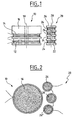
- Figures 1 and 2 show the structure of the collector system of a programmer according to the invention.
- the present invention proposes a particular geometry for these coils, illustrated in Figures 1 and 2.
- the wave collector system comprises at least two coils, as in the embodiment illustrated in FIG. 1, namely a coil transmission / reception 10 essentially intended, in its reception function, to collect the useful signal, and one or more coils called "compensation" 20 intended to essentially collect a component of noise.
- the transmitting / receiving antenna 10 comprises a reception coil 12 and an emission winding 14 wound together around a mandrel 16.
- This mandrel is preferably an air mandrel (without magnetic material such as ferrite), for example cylindrical 18 axis, the largest surface compatible with the physical dimensions from the programmer head. The area in which the communication With the implant can establish itself is thus maximum.
- the compensation antenna 20 comprises a coil 22 wound around a mandrel 26, which is also preferably an air mandrel but of much smaller diameter than the mandrel 16 of the transmitting / receiving antenna.
- the mandrel 26 is disposed collaterally to the mandrel 16, the respective axes 28, 18 of these mandrels being parallel.
- the winding of receiving 12 and the compensation winding 22 to have the same sensitivity to distant disturbances, their number of turns must be inversely proportional to their surface.
- the reception area of the compensation antenna 20 being much smaller than that of the transmitting / receiving antenna 10, the differential well area between the two antennas is limited.
- the winding 22 of the compensation antenna 20 is advantageously divided into several groups of successive turns 24.
- the compensation antenna must not exceed a number of critical turns, corresponding to a maximum inductance limiting the band passing through the system.
- the winding 22 is made of several groups 24 of rows coaxial rows but arranged at a distance from each other on the same mandrel 26.
- the number of turns of the different groups 24 are not identical, so that each group has a frequency different resonance, leading to a global resonance peak less marked for the compensation antenna 20.
- the winding 22 of the compensation antenna can be realized by the so-called honeycomb technique, that is to say with turned turns in ventilated lattice, the least joined possible, forcing an overlap ordered.
- the different groups of turns of the antenna of compensation 20 are distributed over as many different mandrels 26, 26 ', 26 ", to give windings, not coupled together, connected in series.
- the different groups of turns are arranged at a short distance (some centimeters) of the receiving antenna, to avoid falling back on the disadvantage described above coplanar surface antennas equal.
- the overall inductance of the compensation antenna is greatly reduced and its performance in terms of bandwidth is increased.
Abstract
Description
- par rapport à une antenne différentielle à coupelle ferrite (telle que décrite dans le EP-A-0 797 317 précité) : la suppression de la ferrite procure des avantages en terme de volume du cône de détection, prix, poids, solidité, facilité d'intégration, fiabilité et pérennité ;
- par rapport à une construction coaxiale ou concentrique (telle que décrite par exemple dans le WO-A-01/05467 précité) : absence de réduction de portée des signaux proches, en conservant une bonne réjection des perturbations lointaines ;
- par rapport à une construction coplanaire symétrique : réduction de l'aire du puits différentiel ;
- possibilité d'utiliser un seul canal d'amplification, la différence entre les signaux de réception et de compensation pouvant s'effectuer par une simple mise en série et en opposition de phase des enroulements.
Claims (5)
- Un dispositif de réception de signaux émis par un appareil médical actif implanté, ce dispositif comportant des moyens collecteurs d'onde pour la réception d'une induction magnétique comprenant une composante utile émise par l'appareil implanté et une composante parasite d'origine externe, ces moyens collecteurs d'onde comportant au moins une bobine de réception (10) et au moins une bobine de compensation (20),
caractérisé en ce que la bobine de réception (10) et la bobine de compensation (20) comprennent chacune au moins une série de spires (12, 22) enroulées autour de mandrins respectifs (16, 26), de préférence en matériau non magnétique, ces mandrins étant disposés côte à côte avec leurs axes respectifs (18, 28) distants et parallèles et leurs sections n'étant pas concourantes, et la section du mandrin (26) de la bobine de compensation (20) étant inférieure à celle du mandrin (16) de la bobine de réception (10). - Le dispositif de la revendication 1, dans lequel la série de spires (22) de la bobine de compensation (20) est fractionnée en une pluralité de groupes de spires (24) enroulés sur un même mandrin (26) avec espacement axial et reliés en série.
- Le dispositif de la revendication 1, dans lequel les spires de la bobine de compensation sont enroulées en nid d'abeilles.
- Le dispositif de la revendication 1, dans lequel la série de spires (22) de la bobine de compensation (20) est fractionnée en une pluralité de groupes de spires enroulés sur des mandrins distincts (26, 26', 26") et reliés en série, les différents mandrins étant d'axes parallèles et situés à même distance de la bobine de réception.
- Le dispositif de la revendication 2 ou 4, dans lequel les différents groupes de spires de la bobine de compensation présentent des sections d'enroulement et/ou des nombres de spires différents.
Applications Claiming Priority (2)
| Application Number | Priority Date | Filing Date | Title |
|---|---|---|---|
| FR0306461 | 2003-05-28 | ||
| FR0306461A FR2855416B1 (fr) | 2003-05-28 | 2003-05-28 | Systeme de collecteur d'onde pour la reception de signaux d'induction magnetique emis par un appareil medical actif implante |
Publications (2)
| Publication Number | Publication Date |
|---|---|
| EP1481708A1 true EP1481708A1 (fr) | 2004-12-01 |
| EP1481708B1 EP1481708B1 (fr) | 2008-03-05 |
Family
ID=33104496
Family Applications (1)
| Application Number | Title | Priority Date | Filing Date |
|---|---|---|---|
| EP04291335A Active EP1481708B1 (fr) | 2003-05-28 | 2004-05-27 | Système de collecteur d'onde pour la réception de signaux d'induction magnétique émis par un appareil médical actif implanté |
Country Status (5)
| Country | Link |
|---|---|
| US (1) | US7096069B2 (fr) |
| EP (1) | EP1481708B1 (fr) |
| AT (1) | ATE387936T1 (fr) |
| DE (1) | DE602004012191T2 (fr) |
| FR (1) | FR2855416B1 (fr) |
Cited By (2)
| Publication number | Priority date | Publication date | Assignee | Title |
|---|---|---|---|---|
| WO2008042054A3 (fr) * | 2006-09-29 | 2008-06-05 | Second Sight Medical Prod Inc | Ensemble enroulement externe pour prothèses médicales implantables |
| US8214044B2 (en) | 2005-09-01 | 2012-07-03 | Sorin Crm S.A.S. | Telemetry apparatus for communications with an active device implanted in a patient's thoracic region |
Families Citing this family (6)
| Publication number | Priority date | Publication date | Assignee | Title |
|---|---|---|---|---|
| CA2809897A1 (fr) * | 2010-09-01 | 2012-03-08 | Abb Technology Ag | Transformateur refroidi comportant au moins un enroulement en bande |
| US20120203620A1 (en) | 2010-11-08 | 2012-08-09 | Douglas Howard Dobyns | Techniques For Wireless Communication Of Proximity Based Marketing |
| US8929809B2 (en) | 2011-03-22 | 2015-01-06 | Radeum, Inc. | Techniques for wireless communication of proximity based content |
| US8880100B2 (en) | 2011-03-23 | 2014-11-04 | Radium, Inc. | Proximity based social networking |
| US9621228B2 (en) | 2014-08-29 | 2017-04-11 | Freelinc Technologies | Spatially aware communications using radio frequency (RF) communications standards |
| US10164685B2 (en) | 2014-12-31 | 2018-12-25 | Freelinc Technologies Inc. | Spatially aware wireless network |
Citations (2)
| Publication number | Priority date | Publication date | Assignee | Title |
|---|---|---|---|---|
| EP0797317A1 (fr) * | 1996-03-22 | 1997-09-24 | ELA MEDICAL (Société anonyme) | Dispositif de réception de signaux émis par un appareil médical actif implanté |
| WO2001005467A1 (fr) * | 1999-07-19 | 2001-01-25 | Medtronic, Inc. | Systeme medical a telemetrie amelioree |
Family Cites Families (2)
| Publication number | Priority date | Publication date | Assignee | Title |
|---|---|---|---|---|
| FR2714609B1 (fr) * | 1993-12-31 | 1996-03-29 | Ela Medical Sa | Procédé et dispositif collecteur d'ondes, pour extraire un signal utile émis par un appareil médical implanté et mêlé à des signaux parasites. |
| US20020046849A1 (en) | 2000-01-24 | 2002-04-25 | Rapp Martin L. | Methods and apparatus for EMI shielding |
-
2003
- 2003-05-28 FR FR0306461A patent/FR2855416B1/fr not_active Expired - Fee Related
-
2004
- 2004-05-27 DE DE602004012191T patent/DE602004012191T2/de active Active
- 2004-05-27 EP EP04291335A patent/EP1481708B1/fr active Active
- 2004-05-27 AT AT04291335T patent/ATE387936T1/de not_active IP Right Cessation
- 2004-05-28 US US10/857,350 patent/US7096069B2/en active Active
Patent Citations (2)
| Publication number | Priority date | Publication date | Assignee | Title |
|---|---|---|---|---|
| EP0797317A1 (fr) * | 1996-03-22 | 1997-09-24 | ELA MEDICAL (Société anonyme) | Dispositif de réception de signaux émis par un appareil médical actif implanté |
| WO2001005467A1 (fr) * | 1999-07-19 | 2001-01-25 | Medtronic, Inc. | Systeme medical a telemetrie amelioree |
Cited By (4)
| Publication number | Priority date | Publication date | Assignee | Title |
|---|---|---|---|---|
| US8214044B2 (en) | 2005-09-01 | 2012-07-03 | Sorin Crm S.A.S. | Telemetry apparatus for communications with an active device implanted in a patient's thoracic region |
| WO2008042054A3 (fr) * | 2006-09-29 | 2008-06-05 | Second Sight Medical Prod Inc | Ensemble enroulement externe pour prothèses médicales implantables |
| US8010206B2 (en) | 2006-09-29 | 2011-08-30 | Second Sight Medical Products, Inc. | External coil assembly for implantable medical prostheses |
| US8548597B2 (en) | 2006-09-29 | 2013-10-01 | Second Sight Medical Products, Inc. | External coil assembly for implantable medical prostheses |
Also Published As
| Publication number | Publication date |
|---|---|
| ATE387936T1 (de) | 2008-03-15 |
| US7096069B2 (en) | 2006-08-22 |
| EP1481708B1 (fr) | 2008-03-05 |
| US20050010268A1 (en) | 2005-01-13 |
| FR2855416B1 (fr) | 2005-07-29 |
| DE602004012191D1 (de) | 2008-04-17 |
| DE602004012191T2 (de) | 2009-04-02 |
| FR2855416A1 (fr) | 2004-12-03 |
Similar Documents
| Publication | Publication Date | Title |
|---|---|---|
| EP0797317B1 (fr) | Dispositif de réception de signaux émis par un appareil médical actif implanté | |
| EP0811396B1 (fr) | Dispositif de filtrage des signaux émis par un appareil médical, notamment un appareil médical actif implanté | |
| EP0275781B1 (fr) | Procédé de transmission à un dispositif central d'enregistrement de données sismiques collectées par des appareils d'acquisition répartis sur le terrain et dispositif pour sa mise en oeuvre | |
| EP0586286B1 (fr) | Système de transmission de données médicales, sans fil | |
| EP0457690A1 (fr) | Dispositif de liaison sans contact pour relier des tronçons de bus de données de type série | |
| EP1481708B1 (fr) | Système de collecteur d'onde pour la réception de signaux d'induction magnétique émis par un appareil médical actif implanté | |
| FR2981519A1 (fr) | Dispositif de chargement inductif d'un appareil portable integrant une antenne de communication en champ proche | |
| EP2515446B1 (fr) | Récepteur alimenté par une interface sans fil de type inductif | |
| EP0232189B1 (fr) | Antenne orbite pour appareil d'imagerie par résonance magnétique nucléaire | |
| FR2712132A1 (fr) | Système de microphones directionnels à gradient et procédé associé. | |
| EP0661077B1 (fr) | Appareil médical extrayant un signal utile mélé à des signaux parasites | |
| EP1897170A1 (fr) | Entite electronique a antenne magnetique | |
| WO2012140169A1 (fr) | Procede, circuit et dispositif de communication sans contact a emission activee | |
| FR3013069A1 (fr) | Poignee de portiere de vehicule comprenant une antenne de communication en champ proche | |
| EP2541782B1 (fr) | Circuit récepteur de télémétrie RF pour implant médical actif | |
| EP1178500B1 (fr) | Structure intégrée d'inductances à valeurs partagées sur un substrat semiconducteur | |
| FR3004007A1 (fr) | Coupleur large bande | |
| EP2388043A1 (fr) | Procédé de recherche et de sélection d'un canal de télémétrie RF pour l'établissement d'une liaison avec un dispositif médical actif | |
| EP3516736B1 (fr) | Antenne à tiges ferromagnétiques bobinées et couplées entre elles | |
| EP0055636B1 (fr) | Récepteur d'écartométrie pour radar secondaire | |
| EP0613319B1 (fr) | Dispositif multicapteurs de prise de son et de traitement du signal associé | |
| EP4055395B1 (fr) | Détecteur de courant, capteur, système et procédé associés | |
| EP1801914A1 (fr) | Antenne et système de verrouillage/déverrouillage à distance comportant une telle antenne. | |
| FR3116399A1 (fr) | Ensemble radiofréquence à isolation améliorée | |
| FR3133677A1 (fr) | Capteur de champ magnetique pour la mesure d’un courant continu |
Legal Events
| Date | Code | Title | Description |
|---|---|---|---|
| PUAI | Public reference made under article 153(3) epc to a published international application that has entered the european phase |
Free format text: ORIGINAL CODE: 0009012 |
|
| AK | Designated contracting states |
Kind code of ref document: A1 Designated state(s): AT BE BG CH CY CZ DE DK EE ES FI FR GB GR HU IE IT LI LU MC NL PL PT RO SE SI SK TR |
|
| AX | Request for extension of the european patent |
Extension state: AL HR LT LV MK |
|
| 17P | Request for examination filed |
Effective date: 20050531 |
|
| AKX | Designation fees paid |
Designated state(s): AT BE BG CH CY CZ DE DK EE ES FI FR GB GR HU IE IT LI LU MC NL PL PT RO SE SI SK TR |
|
| GRAP | Despatch of communication of intention to grant a patent |
Free format text: ORIGINAL CODE: EPIDOSNIGR1 |
|
| RAP1 | Party data changed (applicant data changed or rights of an application transferred) |
Owner name: ELA MEDICAL |
|
| GRAS | Grant fee paid |
Free format text: ORIGINAL CODE: EPIDOSNIGR3 |
|
| GRAA | (expected) grant |
Free format text: ORIGINAL CODE: 0009210 |
|
| AK | Designated contracting states |
Kind code of ref document: B1 Designated state(s): AT BE BG CH CY CZ DE DK EE ES FI FR GB GR HU IE IT LI LU MC NL PL PT RO SE SI SK TR |
|
| REG | Reference to a national code |
Ref country code: GB Ref legal event code: FG4D Free format text: NOT ENGLISH |
|
| REG | Reference to a national code |
Ref country code: CH Ref legal event code: EP |
|
| REG | Reference to a national code |
Ref country code: IE Ref legal event code: FG4D Free format text: LANGUAGE OF EP DOCUMENT: FRENCH |
|
| REF | Corresponds to: |
Ref document number: 602004012191 Country of ref document: DE Date of ref document: 20080417 Kind code of ref document: P |
|
| REG | Reference to a national code |
Ref country code: SE Ref legal event code: TRGR |
|
| PG25 | Lapsed in a contracting state [announced via postgrant information from national office to epo] |
Ref country code: FI Free format text: LAPSE BECAUSE OF FAILURE TO SUBMIT A TRANSLATION OF THE DESCRIPTION OR TO PAY THE FEE WITHIN THE PRESCRIBED TIME-LIMIT Effective date: 20080305 Ref country code: ES Free format text: LAPSE BECAUSE OF FAILURE TO SUBMIT A TRANSLATION OF THE DESCRIPTION OR TO PAY THE FEE WITHIN THE PRESCRIBED TIME-LIMIT Effective date: 20080616 |
|
| PG25 | Lapsed in a contracting state [announced via postgrant information from national office to epo] |
Ref country code: AT Free format text: LAPSE BECAUSE OF FAILURE TO SUBMIT A TRANSLATION OF THE DESCRIPTION OR TO PAY THE FEE WITHIN THE PRESCRIBED TIME-LIMIT Effective date: 20080305 |
|
| NLV1 | Nl: lapsed or annulled due to failure to fulfill the requirements of art. 29p and 29m of the patents act | ||
| PG25 | Lapsed in a contracting state [announced via postgrant information from national office to epo] |
Ref country code: PL Free format text: LAPSE BECAUSE OF FAILURE TO SUBMIT A TRANSLATION OF THE DESCRIPTION OR TO PAY THE FEE WITHIN THE PRESCRIBED TIME-LIMIT Effective date: 20080305 Ref country code: SI Free format text: LAPSE BECAUSE OF FAILURE TO SUBMIT A TRANSLATION OF THE DESCRIPTION OR TO PAY THE FEE WITHIN THE PRESCRIBED TIME-LIMIT Effective date: 20080305 |
|
| PG25 | Lapsed in a contracting state [announced via postgrant information from national office to epo] |
Ref country code: CZ Free format text: LAPSE BECAUSE OF FAILURE TO SUBMIT A TRANSLATION OF THE DESCRIPTION OR TO PAY THE FEE WITHIN THE PRESCRIBED TIME-LIMIT Effective date: 20080305 Ref country code: SK Free format text: LAPSE BECAUSE OF FAILURE TO SUBMIT A TRANSLATION OF THE DESCRIPTION OR TO PAY THE FEE WITHIN THE PRESCRIBED TIME-LIMIT Effective date: 20080305 Ref country code: NL Free format text: LAPSE BECAUSE OF FAILURE TO SUBMIT A TRANSLATION OF THE DESCRIPTION OR TO PAY THE FEE WITHIN THE PRESCRIBED TIME-LIMIT Effective date: 20080305 Ref country code: PT Free format text: LAPSE BECAUSE OF FAILURE TO SUBMIT A TRANSLATION OF THE DESCRIPTION OR TO PAY THE FEE WITHIN THE PRESCRIBED TIME-LIMIT Effective date: 20080805 |
|
| PG25 | Lapsed in a contracting state [announced via postgrant information from national office to epo] |
Ref country code: RO Free format text: LAPSE BECAUSE OF FAILURE TO SUBMIT A TRANSLATION OF THE DESCRIPTION OR TO PAY THE FEE WITHIN THE PRESCRIBED TIME-LIMIT Effective date: 20080305 |
|
| BERE | Be: lapsed |
Owner name: ELA MEDICAL Effective date: 20080531 |
|
| PG25 | Lapsed in a contracting state [announced via postgrant information from national office to epo] |
Ref country code: MC Free format text: LAPSE BECAUSE OF NON-PAYMENT OF DUE FEES Effective date: 20080531 |
|
| REG | Reference to a national code |
Ref country code: CH Ref legal event code: PL |
|
| PLBE | No opposition filed within time limit |
Free format text: ORIGINAL CODE: 0009261 |
|
| STAA | Information on the status of an ep patent application or granted ep patent |
Free format text: STATUS: NO OPPOSITION FILED WITHIN TIME LIMIT |
|
| PG25 | Lapsed in a contracting state [announced via postgrant information from national office to epo] |
Ref country code: DK Free format text: LAPSE BECAUSE OF FAILURE TO SUBMIT A TRANSLATION OF THE DESCRIPTION OR TO PAY THE FEE WITHIN THE PRESCRIBED TIME-LIMIT Effective date: 20080305 Ref country code: CH Free format text: LAPSE BECAUSE OF NON-PAYMENT OF DUE FEES Effective date: 20080531 Ref country code: LI Free format text: LAPSE BECAUSE OF NON-PAYMENT OF DUE FEES Effective date: 20080531 |
|
| 26N | No opposition filed |
Effective date: 20081208 |
|
| PG25 | Lapsed in a contracting state [announced via postgrant information from national office to epo] |
Ref country code: BE Free format text: LAPSE BECAUSE OF NON-PAYMENT OF DUE FEES Effective date: 20080531 |
|
| PG25 | Lapsed in a contracting state [announced via postgrant information from national office to epo] |
Ref country code: BG Free format text: LAPSE BECAUSE OF FAILURE TO SUBMIT A TRANSLATION OF THE DESCRIPTION OR TO PAY THE FEE WITHIN THE PRESCRIBED TIME-LIMIT Effective date: 20080605 Ref country code: EE Free format text: LAPSE BECAUSE OF FAILURE TO SUBMIT A TRANSLATION OF THE DESCRIPTION OR TO PAY THE FEE WITHIN THE PRESCRIBED TIME-LIMIT Effective date: 20080305 |
|
| PG25 | Lapsed in a contracting state [announced via postgrant information from national office to epo] |
Ref country code: CY Free format text: LAPSE BECAUSE OF FAILURE TO SUBMIT A TRANSLATION OF THE DESCRIPTION OR TO PAY THE FEE WITHIN THE PRESCRIBED TIME-LIMIT Effective date: 20080305 |
|
| PG25 | Lapsed in a contracting state [announced via postgrant information from national office to epo] |
Ref country code: LU Free format text: LAPSE BECAUSE OF NON-PAYMENT OF DUE FEES Effective date: 20080527 Ref country code: HU Free format text: LAPSE BECAUSE OF FAILURE TO SUBMIT A TRANSLATION OF THE DESCRIPTION OR TO PAY THE FEE WITHIN THE PRESCRIBED TIME-LIMIT Effective date: 20080906 |
|
| PG25 | Lapsed in a contracting state [announced via postgrant information from national office to epo] |
Ref country code: TR Free format text: LAPSE BECAUSE OF FAILURE TO SUBMIT A TRANSLATION OF THE DESCRIPTION OR TO PAY THE FEE WITHIN THE PRESCRIBED TIME-LIMIT Effective date: 20080305 |
|
| PG25 | Lapsed in a contracting state [announced via postgrant information from national office to epo] |
Ref country code: GR Free format text: LAPSE BECAUSE OF FAILURE TO SUBMIT A TRANSLATION OF THE DESCRIPTION OR TO PAY THE FEE WITHIN THE PRESCRIBED TIME-LIMIT Effective date: 20080606 |
|
| PGFP | Annual fee paid to national office [announced via postgrant information from national office to epo] |
Ref country code: IE Payment date: 20120510 Year of fee payment: 9 |
|
| PGFP | Annual fee paid to national office [announced via postgrant information from national office to epo] |
Ref country code: SE Payment date: 20120511 Year of fee payment: 9 |
|
| REG | Reference to a national code |
Ref country code: SE Ref legal event code: EUG |
|
| PG25 | Lapsed in a contracting state [announced via postgrant information from national office to epo] |
Ref country code: SE Free format text: LAPSE BECAUSE OF NON-PAYMENT OF DUE FEES Effective date: 20130528 |
|
| REG | Reference to a national code |
Ref country code: IE Ref legal event code: MM4A |
|
| PG25 | Lapsed in a contracting state [announced via postgrant information from national office to epo] |
Ref country code: IE Free format text: LAPSE BECAUSE OF NON-PAYMENT OF DUE FEES Effective date: 20130527 |
|
| REG | Reference to a national code |
Ref country code: FR Ref legal event code: PLFP Year of fee payment: 13 |
|
| REG | Reference to a national code |
Ref country code: FR Ref legal event code: PLFP Year of fee payment: 14 |
|
| REG | Reference to a national code |
Ref country code: FR Ref legal event code: PLFP Year of fee payment: 15 |
|
| PGFP | Annual fee paid to national office [announced via postgrant information from national office to epo] |
Ref country code: IT Payment date: 20220510 Year of fee payment: 19 Ref country code: GB Payment date: 20220519 Year of fee payment: 19 Ref country code: FR Payment date: 20220530 Year of fee payment: 19 Ref country code: DE Payment date: 20220511 Year of fee payment: 19 |
|
| P01 | Opt-out of the competence of the unified patent court (upc) registered |
Effective date: 20230714 |
|
| REG | Reference to a national code |
Ref country code: DE Ref legal event code: R119 Ref document number: 602004012191 Country of ref document: DE |
|
| GBPC | Gb: european patent ceased through non-payment of renewal fee |
Effective date: 20230527 |
|
| PG25 | Lapsed in a contracting state [announced via postgrant information from national office to epo] |
Ref country code: IT Free format text: LAPSE BECAUSE OF NON-PAYMENT OF DUE FEES Effective date: 20230527 Ref country code: DE Free format text: LAPSE BECAUSE OF NON-PAYMENT OF DUE FEES Effective date: 20231201 Ref country code: GB Free format text: LAPSE BECAUSE OF NON-PAYMENT OF DUE FEES Effective date: 20230527 |