EP1481647A1 - Blank from which a customized prosthetic part can be machined - Google Patents
Blank from which a customized prosthetic part can be machined Download PDFInfo
- Publication number
- EP1481647A1 EP1481647A1 EP20040090207 EP04090207A EP1481647A1 EP 1481647 A1 EP1481647 A1 EP 1481647A1 EP 20040090207 EP20040090207 EP 20040090207 EP 04090207 A EP04090207 A EP 04090207A EP 1481647 A1 EP1481647 A1 EP 1481647A1
- Authority
- EP
- European Patent Office
- Prior art keywords
- blank
- connecting elements
- prosthetic
- connecting element
- blank according
- Prior art date
- Legal status (The legal status is an assumption and is not a legal conclusion. Google has not performed a legal analysis and makes no representation as to the accuracy of the status listed.)
- Withdrawn
Links
- 238000003801 milling Methods 0.000 claims description 13
- 239000000560 biocompatible material Substances 0.000 claims description 5
- RTAQQCXQSZGOHL-UHFFFAOYSA-N Titanium Chemical compound [Ti] RTAQQCXQSZGOHL-UHFFFAOYSA-N 0.000 claims description 2
- 239000012620 biological material Substances 0.000 claims description 2
- 229910052719 titanium Inorganic materials 0.000 claims description 2
- 239000010936 titanium Substances 0.000 claims description 2
- 229910010293 ceramic material Inorganic materials 0.000 claims 1
- 238000004519 manufacturing process Methods 0.000 abstract description 8
- 238000011282 treatment Methods 0.000 abstract description 3
- 238000003754 machining Methods 0.000 abstract description 2
- 239000002537 cosmetic Substances 0.000 description 6
- 239000000463 material Substances 0.000 description 5
- 210000000988 bone and bone Anatomy 0.000 description 4
- 241000283690 Bos taurus Species 0.000 description 2
- 239000000919 ceramic Substances 0.000 description 2
- 235000014653 Carica parviflora Nutrition 0.000 description 1
- 241000243321 Cnidaria Species 0.000 description 1
- 230000001934 delay Effects 0.000 description 1
- 210000004513 dentition Anatomy 0.000 description 1
- 238000011161 development Methods 0.000 description 1
- 230000018109 developmental process Effects 0.000 description 1
- 229910052588 hydroxylapatite Inorganic materials 0.000 description 1
- 238000009434 installation Methods 0.000 description 1
- 239000007769 metal material Substances 0.000 description 1
- 238000000034 method Methods 0.000 description 1
- XYJRXVWERLGGKC-UHFFFAOYSA-D pentacalcium;hydroxide;triphosphate Chemical compound [OH-].[Ca+2].[Ca+2].[Ca+2].[Ca+2].[Ca+2].[O-]P([O-])([O-])=O.[O-]P([O-])([O-])=O.[O-]P([O-])([O-])=O XYJRXVWERLGGKC-UHFFFAOYSA-D 0.000 description 1
- 238000009417 prefabrication Methods 0.000 description 1
- 238000004904 shortening Methods 0.000 description 1
- 238000001356 surgical procedure Methods 0.000 description 1
- 230000036346 tooth eruption Effects 0.000 description 1
Images



Classifications
-
- A—HUMAN NECESSITIES
- A61—MEDICAL OR VETERINARY SCIENCE; HYGIENE
- A61C—DENTISTRY; APPARATUS OR METHODS FOR ORAL OR DENTAL HYGIENE
- A61C13/00—Dental prostheses; Making same
- A61C13/0003—Making bridge-work, inlays, implants or the like
- A61C13/0022—Blanks or green, unfinished dental restoration parts
-
- A—HUMAN NECESSITIES
- A61—MEDICAL OR VETERINARY SCIENCE; HYGIENE
- A61C—DENTISTRY; APPARATUS OR METHODS FOR ORAL OR DENTAL HYGIENE
- A61C13/00—Dental prostheses; Making same
- A61C13/0003—Making bridge-work, inlays, implants or the like
-
- Y—GENERAL TAGGING OF NEW TECHNOLOGICAL DEVELOPMENTS; GENERAL TAGGING OF CROSS-SECTIONAL TECHNOLOGIES SPANNING OVER SEVERAL SECTIONS OF THE IPC; TECHNICAL SUBJECTS COVERED BY FORMER USPC CROSS-REFERENCE ART COLLECTIONS [XRACs] AND DIGESTS
- Y10—TECHNICAL SUBJECTS COVERED BY FORMER USPC
- Y10T—TECHNICAL SUBJECTS COVERED BY FORMER US CLASSIFICATION
- Y10T428/00—Stock material or miscellaneous articles
- Y10T428/12—All metal or with adjacent metals
- Y10T428/12229—Intermediate article [e.g., blank, etc.]
-
- Y—GENERAL TAGGING OF NEW TECHNOLOGICAL DEVELOPMENTS; GENERAL TAGGING OF CROSS-SECTIONAL TECHNOLOGIES SPANNING OVER SEVERAL SECTIONS OF THE IPC; TECHNICAL SUBJECTS COVERED BY FORMER USPC CROSS-REFERENCE ART COLLECTIONS [XRACs] AND DIGESTS
- Y10—TECHNICAL SUBJECTS COVERED BY FORMER USPC
- Y10T—TECHNICAL SUBJECTS COVERED BY FORMER US CLASSIFICATION
- Y10T428/00—Stock material or miscellaneous articles
- Y10T428/24—Structurally defined web or sheet [e.g., overall dimension, etc.]
- Y10T428/24355—Continuous and nonuniform or irregular surface on layer or component [e.g., roofing, etc.]
-
- Y—GENERAL TAGGING OF NEW TECHNOLOGICAL DEVELOPMENTS; GENERAL TAGGING OF CROSS-SECTIONAL TECHNOLOGIES SPANNING OVER SEVERAL SECTIONS OF THE IPC; TECHNICAL SUBJECTS COVERED BY FORMER USPC CROSS-REFERENCE ART COLLECTIONS [XRACs] AND DIGESTS
- Y10—TECHNICAL SUBJECTS COVERED BY FORMER USPC
- Y10T—TECHNICAL SUBJECTS COVERED BY FORMER US CLASSIFICATION
- Y10T428/00—Stock material or miscellaneous articles
- Y10T428/31504—Composite [nonstructural laminate]
- Y10T428/31678—Of metal
Definitions
- the present invention relates to a blank used to manufacture customized prosthetic components, more particularly, abutments of dental prosthetic replacements.
- the present invention relates to a blank that facilitates the rapid and economical production of dental prosthetic components.
- Dental prosthetic components normally made from ceramic or metallic materials, are used to functionally substitute a part of a patient's dentition.
- Two alternative types of cosmetic substitutes for teeth are bridges (which anchor a substitute tooth on the adjacent teeth), and inlays (which simply fill a missing portion of an existing tooth). These components aren't necessarily used all at once, some patients may need only cosmetic substitutes while others need a full replacement.
- the present invention pre-integrates the connecting element into the design of the blank that will be cut, thus allowing the remaining dental prosthetic components to be manufactured inside the dental office, (often using the same CAD/CAM equipment already applied in making the cosmetic parts), and consequently helping to further reduce the time needed to treat a patient.
- the present invention allows for the fast and economical production of customized dental prosthetic components, by providing a blank with pre-fabricated connecting elements. Since connecting elements have standardized dimensions with few discrete variations, they can be easily mass-produced into the blanks. By pre-fabricating the connecting element into the blank's design, all that remains to be done in the dental office is to custom form the outer part of the blank according to the specific need of the patient. This operation is much simpler, and can be achieved with most of the currently available CAD/CAM systems for the dental office.
- a blank used for machining customized prosthetic components which includes a support geometry that allows the blank to be attached to a milling machine; one or more pre-fabricated connecting elements that allow the resulting prosthetic component to be properly connected to other prosthetic components; and access paths for fastening screws which will later be used to secure the prosthetic components together.
- the connecting element of a prosthetic component is the geometry used to align and lock the element from rotating relative to a joined second prosthetic component, these are often presented as hexagonal connectors or Morse Cones, but other geometries may also be applied.
- the pre-fabricated connecting elements are shaped as anti-rotation hexagons or Morse Cones.
- fixtures which are installed into the patient's bone
- a seating surface which is the surface of the part that contains the connecting element
- a corresponding abutment the part that replicates the tooth's internal structure
- the joined connecting elements from both parts would prevent the parts from rotating thus maintaining alignment between the parts.
- parts with more than one connecting element may be required.
- the present invention also resolves this situation because the blank can have more than one connecting element. In case of multiple connecting elements, a template would have to be used during the surgical procedure (installation of the fixture) to ensure proper alignment later on.
- the blank In order to facilitate the milling operation of a prosthetic component, the blank must also include a support geometry, used to fasten the blank in the milling machine that will perform the customization.
- This support geometry may range from a simple elongation of the stub, to more complex one-step-locking designs.
- An example of one-step-locking design would be a Morse-Cone, where the geometry forces the part to lock once it is put into place.
- the blank must include the access paths for fastening screws, which will be used later to secure the different prosthetic components together.
- figures 1, 2, and 3 show current state of the art on blanks for milling dental crowns, bridges or inlays;
- Figure 4 shows the supporting element from related U.S. Patent 6,224,371, joined with the blank proposed in this invention;
- figures 5-10 show variations of the present invention.
- Improvements in the art include allowing for final parts to be cut at a low cost, directly where the part will be used.
- the pre-fabrication of connecting elements (5) into the blanks (FIGS 4 to 10) exclude the need for any future milling on the part, once customization is done, thus simplifying the build process for a prosthetic component.
- the critical characteristic is the connecting element (5)
- other shape defaults such as outer shape, aren't as critical and can be provided in such a way that best suits the user's requirements.
- the general orientation between blank and connecting elements, that is the direction (or surface) where it occurs on the blank is not a factor in fixating the blank to the milling machine.
- the blank proposed in this invention can be fastened to the milling machine by any of its surfaces, and, similarly, the connecting element can appear pre-fabricated in any of the blank's surfaces.
- FIG.4 shows the support stub (10) containing the connecting element presented in related U.S. Patent 6,224,371, along with the blank (6) containing the connecting element (5) and access path (7) for fastening screw (11) presented in this invention.
- FIG.5 Presents a variation of the present invention where the blank (6) containing the connecting element (5) and access path for screws (7) is cemented (8) to a supporting stub (9) similar to (1) .
- FIG.6 Presents a variation of the present invention where the blank (6) containing the connecting element (5) and access path for screws (7) includes the support geometry (9) .
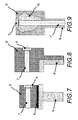
- FIGS. 7 and 8 Present variations of FIGS 5 and 6 , where the connecting elements (5) are pre-fabricated in a different face of the blank.
- FIG.2 Mo ⁇ rmann et al. described in U.S Patent 4,615,678 a blank, shown in FIG.2 , that allowed the milling of prosthetic components on location. That blank, however included two parts that where cemented (2) together, a block (3) from which the final piece would be cut, and a supporting stub (1) , shown in FIG.1 .
- a variant type blank (4) (shown in FIG.3 ) composed exclusively of one kind of material, is used in some CAD/CAM systems (an example of which would be Cynovad) to fabricate crowns and bridges, but doesn't allow abutments to be milled because it lacks the presence of a connecting element.
- Other examples available in industry generally present the same ability to perform inlays, crowns and bridges, but lack the expansion potential to abutments because they lack the connecting element.
- FIG.9 Schematically represents a prosthetic component (12) cut from the blank (6) proposed in the present invention.
- the blank is attached to the milling machine through the support geometry (9) so that it is securely fastened and can be properly cut.
- the presence of the pre-fabricated connecting element (5) at the base of the finalized part can be noticed, along with access path (7) for the screw that will later be used to fasten this component to other prosthetic parts.
- FIG.10 presents the blank (6) from the present invention with more than one connecting element (5) , and a schematic representation of a prosthetic component (13) to be cut from the blank (6) .
- This variant of the proposed blank also contains a support geometry (9) so that it can be properly attached to the milling machine.
- This blank (6) may be composed of different kinds of biocompatible materials, normally Titanium or ceramic type materials are used, Biomaterials (including human or bovine Demineralized Freeze Bone Dry Allograft (DFBDA); human or bovine Freeze Bone Dry Allograft (FBDA); or, synthetic or coral hydroxyapatite, amongst others currently being developed) may also be applied, but ultimately the material that should be used is the one that best suits the patients' need.
- DFBDA human or bovine Demineralized Freeze Bone Dry Allograft
- FBDA human or bovine Freeze Bone Dry Allograft
- synthetic or coral hydroxyapatite amongst others currently being developed
Landscapes
- Health & Medical Sciences (AREA)
- Oral & Maxillofacial Surgery (AREA)
- Dentistry (AREA)
- Epidemiology (AREA)
- Life Sciences & Earth Sciences (AREA)
- Animal Behavior & Ethology (AREA)
- General Health & Medical Sciences (AREA)
- Public Health (AREA)
- Veterinary Medicine (AREA)
- Prostheses (AREA)
Abstract
Description
- The present invention relates to a blank used to manufacture customized prosthetic components, more particularly, abutments of dental prosthetic replacements.
- The present invention relates to a blank that facilitates the rapid and economical production of dental prosthetic components. Dental prosthetic components, normally made from ceramic or metallic materials, are used to functionally substitute a part of a patient's dentition. There are three major components used in a complete prosthetic restoration, a substitute for the tooth's root (called a fixture), a substitute for a tooth's internal structure (called an abutment), and a cosmetic substitute, which replaces the tooth's appearance (called a crown). Two alternative types of cosmetic substitutes for teeth are bridges (which anchor a substitute tooth on the adjacent teeth), and inlays (which simply fill a missing portion of an existing tooth). These components aren't necessarily used all at once, some patients may need only cosmetic substitutes while others need a full replacement.
- Normally, when a patient needs a prosthetic replacement, several surgical and laboratory steps must be completed before the actual replacement is ready to be installed. These steps range from installing fixtures into the patient's bones to fabricating the prosthetic replacement (which includes both abutment and crown) itself. One thing that must be understood is that regardless of the kind of treatment the patient is undergoing, time is the crucial element. The longer it takes to properly treat a medical condition, the further the scenario deteriorates, thus the bigger the problem that needs to be solved. Recent developments in the art have allowed for cosmetic substitutes (namely crowns, bridges, or inlays) to be manufactured by CAD/CAM devices, directly in the dentist's office (sometimes referred to as chair-side systems), thus shortening the time between a patient's admittance to his release. However helpful, cosmetic replacements are seldom used alone, and treatments that require other prosthetic components must still endure the delays involved in fabricating the remaining components. The main reason current chair-side CAD/CAM systems cannot manufacture abutments or fixtures is the high degree of precision required to manufacture the connecting elements, which join the two prosthetic components together ensuring their proper alignment and securing them from rotating once installed. Since most chair-side systems cannot achieve said high degree of precision during milling, these machines cannot produce abutments or fixtures using their current blanks (the block of material from which they cut their final part). The present invention pre-integrates the connecting element into the design of the blank that will be cut, thus allowing the remaining dental prosthetic components to be manufactured inside the dental office, (often using the same CAD/CAM equipment already applied in making the cosmetic parts), and consequently helping to further reduce the time needed to treat a patient.
- The present invention allows for the fast and economical production of customized dental prosthetic components, by providing a blank with pre-fabricated connecting elements. Since connecting elements have standardized dimensions with few discrete variations, they can be easily mass-produced into the blanks. By pre-fabricating the connecting element into the blank's design, all that remains to be done in the dental office is to custom form the outer part of the blank according to the specific need of the patient. This operation is much simpler, and can be achieved with most of the currently available CAD/CAM systems for the dental office. In this sense, a blank used for machining customized prosthetic components is provided which includes a support geometry that allows the blank to be attached to a milling machine; one or more pre-fabricated connecting elements that allow the resulting prosthetic component to be properly connected to other prosthetic components; and access paths for fastening screws which will later be used to secure the prosthetic components together.
- The connecting element of a prosthetic component is the geometry used to align and lock the element from rotating relative to a joined second prosthetic component, these are often presented as hexagonal connectors or Morse Cones, but other geometries may also be applied. In a preferred embodiment of the present invention the pre-fabricated connecting elements are shaped as anti-rotation hexagons or Morse Cones. For example, fixtures (which are installed into the patient's bone) may have a seating surface (which is the surface of the part that contains the connecting element) with an hexagonal connecting element and a corresponding abutment (the part that replicates the tooth's internal structure) would have the corresponding hexagonal connecting element on its seating surface, so that when coupled together, the joined connecting elements from both parts would prevent the parts from rotating thus maintaining alignment between the parts. Depending on the dental reconstruction, parts with more than one connecting element may be required. The present invention also resolves this situation because the blank can have more than one connecting element. In case of multiple connecting elements, a template would have to be used during the surgical procedure (installation of the fixture) to ensure proper alignment later on.
- In order to facilitate the milling operation of a prosthetic component, the blank must also include a support geometry, used to fasten the blank in the milling machine that will perform the customization. This support geometry may range from a simple elongation of the stub, to more complex one-step-locking designs. An example of one-step-locking design would be a Morse-Cone, where the geometry forces the part to lock once it is put into place.
- Finally, the blank must include the access paths for fastening screws, which will be used later to secure the different prosthetic components together.
- Briefly, figures 1, 2, and 3 show current state of the art on blanks for milling dental crowns, bridges or inlays; Figure 4 shows the supporting element from related U.S. Patent 6,224,371, joined with the blank proposed in this invention; finally figures 5-10 show variations of the present invention.
- FIG.1: Presents the supporting stub currently used to fasten blanks in milling machines;
- FIG.2: Shows the block from which the actual final crown, bridge, or inlay will be cut is shown cemented to the supporting stub shown in FIG.1;
- FIG.3: Presents a variation of the current state of the art where the supporting stub is already made from the material from which the final part will be cut;
- FIG.4: Shows the support stub containing the connecting element presented in related U.S. Patent 6,224,371, along with the blank containing the connecting element presented in this invention;
- FIG.5: Illustrates a variation of the present invention where the blank containing the connecting element is cemented to the supporting stub;
- FIG.6: Presents a variation of the present invention where the blank containing the connecting element includes the support geometry;
- FIGS. 7 and 8: Show variations of FIGS 5 and 6, where the connecting elements are pre-fabricated in a different face of the blank;
- FIG.9: Schematically represents a prosthetic component cut from the blank proposed in the present invention;
- FIG.10: Illustrates the blank from the present invention with more than one connecting element, and a schematic representation of a prosthetic component to be cut from the blank.
-
- Improvements in the art include allowing for final parts to be cut at a low cost, directly where the part will be used. The pre-fabrication of connecting elements (5) into the blanks (FIGS 4 to 10) exclude the need for any future milling on the part, once customization is done, thus simplifying the build process for a prosthetic component.
- When designing the blank, the critical characteristic is the connecting element (5), other shape defaults, such as outer shape, aren't as critical and can be provided in such a way that best suits the user's requirements. The general orientation between blank and connecting elements, that is the direction (or surface) where it occurs on the blank is not a factor in fixating the blank to the milling machine. The blank proposed in this invention can be fastened to the milling machine by any of its surfaces, and, similarly, the connecting element can appear pre-fabricated in any of the blank's surfaces.
- FIG.4 shows the support stub (10) containing the connecting element presented in related U.S. Patent 6,224,371, along with the blank (6) containing the connecting element (5) and access path (7) for fastening screw (11) presented in this invention.
- FIG.5 Presents a variation of the present invention where the blank (6) containing the connecting element (5) and access path for screws (7) is cemented (8) to a supporting stub (9) similar to (1).
- FIG.6 Presents a variation of the present invention where the blank (6) containing the connecting element (5) and access path for screws (7) includes the support geometry (9).
- FIGS. 7 and 8, Present variations of FIGS 5 and 6, where the connecting elements (5) are pre-fabricated in a different face of the blank.
- Moërmann et al. described in U.S Patent 4,615,678 a blank, shown in FIG.2, that allowed the milling of prosthetic components on location. That blank, however included two parts that where cemented (2) together, a block (3) from which the final piece would be cut, and a supporting stub (1), shown in FIG.1. A variant type blank (4) (shown in FIG.3) composed exclusively of one kind of material, is used in some CAD/CAM systems (an example of which would be Cynovad) to fabricate crowns and bridges, but doesn't allow abutments to be milled because it lacks the presence of a connecting element. Other examples available in industry, generally present the same ability to perform inlays, crowns and bridges, but lack the expansion potential to abutments because they lack the connecting element.
- The improvement in the art presented by this invention, allows for CAD/CAM machines, currently limited in their ability to manufacture prosthetic components, to expand their universe of possibilities into the realm of abutments and fixtures.
- FIG.9 Schematically represents a prosthetic component (12) cut from the blank (6) proposed in the present invention. The blank is attached to the milling machine through the support geometry (9) so that it is securely fastened and can be properly cut. The presence of the pre-fabricated connecting element (5) at the base of the finalized part can be noticed, along with access path (7) for the screw that will later be used to fasten this component to other prosthetic parts.
- FIG.10 presents the blank (6) from the present invention with more than one connecting element (5), and a schematic representation of a prosthetic component (13) to be cut from the blank (6). Once again, notice the presence on the pre-fabricated connecting elements (5) and screw paths (7) in the final part (13).
- This variant of the proposed blank also contains a support geometry (9) so that it can be properly attached to the milling machine.
- Whereas co-owned U.S. Pat. 6,224,371 proposes a supporting device, the present invention relates to the entire blank, part which will actually be cut. This blank (6) may be composed of different kinds of biocompatible materials, normally Titanium or ceramic type materials are used, Biomaterials (including human or bovine Demineralized Freeze Bone Dry Allograft (DFBDA); human or bovine Freeze Bone Dry Allograft (FBDA); or, synthetic or coral hydroxyapatite, amongst others currently being developed) may also be applied, but ultimately the material that should be used is the one that best suits the patients' need.
Claims (7)
- A blank from which a customized prosthetic component can be machined, made from a biocompatible material, including connecting elements comprising:a support geometry that allows the blank to be attached to a milling machine;one or more pre-fabricated connecting elements that allow the resulting prosthetic component to be properly connected to other prosthetic components; andaccess paths for fastening screws which will be used later to secure the prosthetic components together.
- Blank according to claim 1 wherein the biocompatible material is Titanium.
- Blank according to claim 1 wherein the biocompatible material is a ceramic material.
- Blank according to claim 1 wherein the biocompatible material is a biomaterial.
- Blank according to claim 1 wherein the pre-fabricated connecting elements are shaped as anti-rotation hexagons.
- Blank according to claim 1 wherein the pre-fabricated connecting elements are shaped as Morse-Cones.
- Blank according to claim 1 wherein the customized prosthetic component is an abutment used in dental prosthetic restorations.
Applications Claiming Priority (2)
| Application Number | Priority Date | Filing Date | Title |
|---|---|---|---|
| US446933 | 1982-12-06 | ||
| US10/446,933 US6991853B2 (en) | 2003-05-29 | 2003-05-29 | Blank from which a customized prosthetic part can be machined |
Publications (1)
| Publication Number | Publication Date |
|---|---|
| EP1481647A1 true EP1481647A1 (en) | 2004-12-01 |
Family
ID=33131577
Family Applications (1)
| Application Number | Title | Priority Date | Filing Date |
|---|---|---|---|
| EP20040090207 Withdrawn EP1481647A1 (en) | 2003-05-29 | 2004-05-26 | Blank from which a customized prosthetic part can be machined |
Country Status (3)
| Country | Link |
|---|---|
| US (3) | US6991853B2 (en) |
| EP (1) | EP1481647A1 (en) |
| BR (1) | BRPI0401839A (en) |
Cited By (5)
| Publication number | Priority date | Publication date | Assignee | Title |
|---|---|---|---|---|
| EP2286759A2 (en) | 2009-08-20 | 2011-02-23 | Ivoclar Vivadent AG | Holder for CAD/CAM Blanks |
| WO2013135687A1 (en) * | 2012-03-12 | 2013-09-19 | Prowital Gmbh | Retaining device for abutment blanks |
| WO2014140002A1 (en) * | 2013-03-11 | 2014-09-18 | Bruno Spindler | Milling blank for an abutment attachment |
| ITMI20131561A1 (en) * | 2013-09-23 | 2015-03-24 | Dental Knowledge S R L | METHOD OF REALIZING A DENTAL PROSTHESIS |
| EP2637598B1 (en) | 2010-11-10 | 2017-07-19 | Heraeus Kulzer GmbH | Dental bridges and superstructures, and methods for manufacturing thereof |
Families Citing this family (24)
| Publication number | Priority date | Publication date | Assignee | Title |
|---|---|---|---|---|
| US7534213B2 (en) * | 2002-09-09 | 2009-05-19 | Kneebourne Therapeutic, Llc | Knee extension treatment apparatus |
| DE10322762B4 (en) * | 2003-05-19 | 2013-12-05 | Sirona Dental Systems Gmbh | Holder for a blank and method for measuring the position and orientation of the holder |
| US6991853B2 (en) * | 2003-05-29 | 2006-01-31 | Biogénie Projetos Ltda. | Blank from which a customized prosthetic part can be machined |
| EP1506745A1 (en) * | 2003-08-15 | 2005-02-16 | Jeanette Mörmann | Blank and method for making a dental restoration |
| US20060172263A1 (en) * | 2005-02-01 | 2006-08-03 | D4D Technologies, Lp | Mill blank |
| DE102006021640B3 (en) * | 2006-05-08 | 2007-10-11 | Sirona Dental Systems Gmbh | Dental prosthesis part producing method for use in tooth technician laboratory, involves specifying aesthetically relevant partial construction surface as part of outer surface of dental prosthesis part |
| ATE466540T2 (en) * | 2006-08-25 | 2010-05-15 | Biomain Ab | DENTAL SUPERSTRUCTURE AND METHOD FOR PRODUCING IT |
| DE102007029105A1 (en) * | 2007-06-21 | 2008-12-24 | Zipprich, Holger | Shaping and or cutting lab implant |
| US8568897B2 (en) | 2007-07-20 | 2013-10-29 | Ivoclar Vivadent Ag | Addressable matrices/cluster blanks for dental CAD/CAM systems and optimization thereof |
| US8551622B2 (en) * | 2007-07-20 | 2013-10-08 | Ivoclar Vivadent Ag | Addressable matrices/cluster blanks for dental CAD/CAM systems and optimization thereof |
| DE102007043837B4 (en) * | 2007-09-14 | 2014-02-13 | Ivoclar Vivadent Ag | blank arrangement |
| US8443502B2 (en) * | 2007-09-14 | 2013-05-21 | Ivoclar Vivadent Ag | Blank arrangement |
| EP2965712B1 (en) * | 2014-07-07 | 2019-01-30 | Kulzer GmbH | Improved device for supporting preformed elements for producing single superstructures for dental prostheses and system for supporting this device on the processing machine of said preformed elements |
| DE102014015423A1 (en) * | 2014-10-20 | 2016-04-21 | Amann Girrbach Ag | Milling machine and blank of a dental component |
| BE1022571B1 (en) | 2014-10-24 | 2016-06-08 | Novoden Tec bvba | Instrument for position measurement of lower jaw and method in which such instrument is applied. |
| US10010386B2 (en) | 2015-03-24 | 2018-07-03 | Ivoclar Vivadent Ag | Dental blank holder |
| BR102015018460B1 (en) | 2015-07-31 | 2020-12-01 | Jjgc Indústria E Comércio De Materiais Dentários S.A. | scanning protractor and method for making it |
| USD769449S1 (en) * | 2015-08-03 | 2016-10-18 | James R. Glidewell Dental Ceramics, Inc. | Dental restoration preform |
| USD781428S1 (en) * | 2015-08-03 | 2017-03-14 | James R. Glidewell Dental Ceramics, Inc. | Dental restoration preform |
| DE102016119934A1 (en) * | 2016-10-19 | 2018-05-03 | Degudent Gmbh | Method for producing a blank, blank and a dental restoration |
| EP3448305B1 (en) | 2017-03-09 | 2020-12-30 | Novoden Tec BVBA | Instrument for measuring the position of the lower jaw and method whereby such an instrument is applied and produced |
| DE102017221344A1 (en) * | 2017-11-28 | 2019-05-29 | Sirona Dental Systems Gmbh | Denture mold block and method for producing a dental prosthesis part from the denture mold block |
| USD939712S1 (en) | 2019-11-01 | 2021-12-28 | James R. Glidewell Dental Ceramics, Inc. | Dental restoration preform |
| USD997363S1 (en) | 2021-11-19 | 2023-08-29 | James R. Glidewell Dental Ceramics, Inc. | Multi-unit dental restoration preform |
Citations (4)
| Publication number | Priority date | Publication date | Assignee | Title |
|---|---|---|---|---|
| WO1996025120A1 (en) * | 1993-12-23 | 1996-08-22 | Adt Advanced Dental Technologies Ltd. | Implant abutment systems, devices, and techniques |
| US5775911A (en) * | 1995-01-20 | 1998-07-07 | Thera Patent Gmbh & Co., Kg Gesellschaft Fuer Industrielle Schutzrechte | Method and apparatus for producing a shaped article by sonoerosion |
| US6224371B1 (en) | 1998-12-29 | 2001-05-01 | Silvio De Luca | Supporting device for the manufacture of dental prosthetic components |
| WO2001035854A1 (en) * | 1999-11-17 | 2001-05-25 | 3M Innovative Properties Company | Mill blank for dental prosthesis |
Family Cites Families (5)
| Publication number | Priority date | Publication date | Assignee | Title |
|---|---|---|---|---|
| CH665551A5 (en) * | 1984-03-06 | 1988-05-31 | Werner Hans Dr Med De Moermann | BLANK FOR THE MANUFACTURE OF DENTAL TECHNOLOGY MOLDED PARTS. |
| SE469158B (en) * | 1991-11-01 | 1993-05-24 | Nobelpharma Ab | DENTAL SENSOR DEVICE INTENDED TO BE USED IN CONNECTION WITH CONTROL OF A WORKING EQUIPMENT |
| US5759036A (en) * | 1996-07-29 | 1998-06-02 | Hinds; Kenneth F. | Complete dental implant system and method |
| DE10322762B4 (en) * | 2003-05-19 | 2013-12-05 | Sirona Dental Systems Gmbh | Holder for a blank and method for measuring the position and orientation of the holder |
| US6991853B2 (en) * | 2003-05-29 | 2006-01-31 | Biogénie Projetos Ltda. | Blank from which a customized prosthetic part can be machined |
-
2003
- 2003-05-29 US US10/446,933 patent/US6991853B2/en not_active Expired - Lifetime
-
2004
- 2004-05-26 EP EP20040090207 patent/EP1481647A1/en not_active Withdrawn
- 2004-05-27 BR BRPI0401839 patent/BRPI0401839A/en not_active Application Discontinuation
-
2005
- 2005-06-23 US US11/159,133 patent/US20050239020A1/en not_active Abandoned
- 2005-06-23 US US11/159,132 patent/US20050238903A1/en not_active Abandoned
Patent Citations (4)
| Publication number | Priority date | Publication date | Assignee | Title |
|---|---|---|---|---|
| WO1996025120A1 (en) * | 1993-12-23 | 1996-08-22 | Adt Advanced Dental Technologies Ltd. | Implant abutment systems, devices, and techniques |
| US5775911A (en) * | 1995-01-20 | 1998-07-07 | Thera Patent Gmbh & Co., Kg Gesellschaft Fuer Industrielle Schutzrechte | Method and apparatus for producing a shaped article by sonoerosion |
| US6224371B1 (en) | 1998-12-29 | 2001-05-01 | Silvio De Luca | Supporting device for the manufacture of dental prosthetic components |
| WO2001035854A1 (en) * | 1999-11-17 | 2001-05-25 | 3M Innovative Properties Company | Mill blank for dental prosthesis |
Cited By (11)
| Publication number | Priority date | Publication date | Assignee | Title |
|---|---|---|---|---|
| EP2286759A2 (en) | 2009-08-20 | 2011-02-23 | Ivoclar Vivadent AG | Holder for CAD/CAM Blanks |
| EP2637598B1 (en) | 2010-11-10 | 2017-07-19 | Heraeus Kulzer GmbH | Dental bridges and superstructures, and methods for manufacturing thereof |
| WO2013135687A1 (en) * | 2012-03-12 | 2013-09-19 | Prowital Gmbh | Retaining device for abutment blanks |
| WO2014140002A1 (en) * | 2013-03-11 | 2014-09-18 | Bruno Spindler | Milling blank for an abutment attachment |
| KR20160007494A (en) * | 2013-03-11 | 2016-01-20 | 브루노 스핀들러 | Milling blank for an abutment attachment |
| CN105283148A (en) * | 2013-03-11 | 2016-01-27 | 布鲁诺·斯宾德勒 | Milled blanks for abutment attachments |
| DE102013102402B4 (en) * | 2013-03-11 | 2018-10-11 | Bruno Spindler | MILLING ROLL FOR AN ABUTMENT PACK |
| KR101982823B1 (en) * | 2013-03-11 | 2019-05-29 | 브루노 스핀들러 | Milling blank for an abutment attachment |
| ITMI20131561A1 (en) * | 2013-09-23 | 2015-03-24 | Dental Knowledge S R L | METHOD OF REALIZING A DENTAL PROSTHESIS |
| WO2015044862A1 (en) * | 2013-09-23 | 2015-04-02 | Dental Knowledge S.R.L. | A method for manufacturing a dental prosthesis |
| US10245123B2 (en) | 2013-09-23 | 2019-04-02 | Dental Knowledge S.R.L. | Method for manufacturing a dental prosthesis |
Also Published As
| Publication number | Publication date |
|---|---|
| BRPI0401839A (en) | 2005-03-22 |
| US6991853B2 (en) | 2006-01-31 |
| US20050238903A1 (en) | 2005-10-27 |
| US20040241464A1 (en) | 2004-12-02 |
| US20050239020A1 (en) | 2005-10-27 |
Similar Documents
| Publication | Publication Date | Title |
|---|---|---|
| US6991853B2 (en) | Blank from which a customized prosthetic part can be machined | |
| US11173017B2 (en) | Overdenture and dental implant framework | |
| Rangert et al. | Load factor control for implants in the posterior partially edentulous segment. | |
| US6537069B1 (en) | Method and apparatus for dental implants | |
| US7632095B2 (en) | Method for forming a dental prosthesis | |
| RU2625280C2 (en) | Tooth pin for dental prosthesis support and method of its manufacture | |
| Weigl et al. | Advanced biomaterials used for a new telescopic retainer for removable dentures: ceramic vs. electroplated gold copings: part II. Clinical effects | |
| US20180049849A1 (en) | Digital full arch apparatus and method for immediate definitive dental prostheses | |
| KR20050074282A (en) | Dental abutment plastics coping | |
| JP2021526400A (en) | Central gingival implant system | |
| Tribst et al. | Dental biomechanics of root-analog implants in different bone types | |
| JP2609026B2 (en) | Implant one-sided denture | |
| KR101663623B1 (en) | Separable block for implant Structure manufacturing | |
| KR102500193B1 (en) | A dual fixation system for prosthetics on dental implants that allows the prosthesis to be properly screwed or clipped. | |
| US12350124B2 (en) | Transepithelial abutment | |
| EP3838214B1 (en) | A cad method for generating a virtual superstructure for a customized dental prosthesis and providing the same. | |
| Lee et al. | Fracture load and retention of milled interim implant restorations fabricated on three types of abutments and two implant diameters: An in vitro study | |
| Korsel | 3D finite element stress analysis of different abutment materials in screw, implant and cortical bone | |
| EP3888587A1 (en) | Transepithelial abutment | |
| US11701206B2 (en) | System of triple abutments with TConnect | |
| Andore et al. | Study of effects of different profiles of dental implant using fea | |
| KR102882463B1 (en) | Abutment for dental | |
| ÇİRİŞ et al. | The Effect of Different Framework Fabrication Techniques on Marginal Adaptation in All-on-4 Implant-Supported Fixed Prostheses | |
| Gottlander et al. | Efficient manufacturing, precision fit, and biocompatibility in the Procera technique for fabricating dental prostheses. | |
| KR20250051262A (en) | Minimal implant manufacturing method for edentulous patients |
Legal Events
| Date | Code | Title | Description |
|---|---|---|---|
| PUAI | Public reference made under article 153(3) epc to a published international application that has entered the european phase |
Free format text: ORIGINAL CODE: 0009012 |
|
| AK | Designated contracting states |
Kind code of ref document: A1 Designated state(s): AT BE BG CH CY CZ DE DK EE ES FI FR GB GR HU IE IT LI LU MC NL PL PT RO SE SI SK TR |
|
| AX | Request for extension of the european patent |
Extension state: AL HR LT LV MK |
|
| 17P | Request for examination filed |
Effective date: 20050601 |
|
| AKX | Designation fees paid |
Designated state(s): AT BE BG CH CY CZ DE DK EE ES FI FR GB GR HU IE IT LI LU MC NL PL PT RO SE SI SK TR |
|
| 17Q | First examination report despatched |
Effective date: 20090205 |
|
| STAA | Information on the status of an ep patent application or granted ep patent |
Free format text: STATUS: THE APPLICATION IS DEEMED TO BE WITHDRAWN |
|
| 18D | Application deemed to be withdrawn |
Effective date: 20100316 |