EP1480297A1 - Wire presentation device for power splice terminal - Google Patents
Wire presentation device for power splice terminal Download PDFInfo
- Publication number
- EP1480297A1 EP1480297A1 EP04252876A EP04252876A EP1480297A1 EP 1480297 A1 EP1480297 A1 EP 1480297A1 EP 04252876 A EP04252876 A EP 04252876A EP 04252876 A EP04252876 A EP 04252876A EP 1480297 A1 EP1480297 A1 EP 1480297A1
- Authority
- EP
- European Patent Office
- Prior art keywords
- guide member
- presentation device
- wire
- terminal
- guard wall
- Prior art date
- Legal status (The legal status is an assumption and is not a legal conclusion. Google has not performed a legal analysis and makes no representation as to the accuracy of the status listed.)
- Withdrawn
Links
- 238000002788 crimping Methods 0.000 claims abstract description 30
- WABPQHHGFIMREM-UHFFFAOYSA-N lead(0) Chemical compound [Pb] WABPQHHGFIMREM-UHFFFAOYSA-N 0.000 claims description 17
- 238000004804 winding Methods 0.000 description 8
- 238000009413 insulation Methods 0.000 description 6
- 238000000034 method Methods 0.000 description 5
- 230000001010 compromised effect Effects 0.000 description 3
- 239000004020 conductor Substances 0.000 description 3
- 230000003247 decreasing effect Effects 0.000 description 2
- 230000004888 barrier function Effects 0.000 description 1
- 238000000576 coating method Methods 0.000 description 1
- 239000002320 enamel (paints) Substances 0.000 description 1
- 238000004519 manufacturing process Methods 0.000 description 1
- 230000004048 modification Effects 0.000 description 1
- 238000012986 modification Methods 0.000 description 1
Images


Classifications
-
- H—ELECTRICITY
- H01—ELECTRIC ELEMENTS
- H01R—ELECTRICALLY-CONDUCTIVE CONNECTIONS; STRUCTURAL ASSOCIATIONS OF A PLURALITY OF MUTUALLY-INSULATED ELECTRICAL CONNECTING ELEMENTS; COUPLING DEVICES; CURRENT COLLECTORS
- H01R43/00—Apparatus or processes specially adapted for manufacturing, assembling, maintaining, or repairing of line connectors or current collectors or for joining electric conductors
- H01R43/04—Apparatus or processes specially adapted for manufacturing, assembling, maintaining, or repairing of line connectors or current collectors or for joining electric conductors for forming connections by deformation, e.g. crimping tool
- H01R43/048—Crimping apparatus or processes
- H01R43/052—Crimping apparatus or processes with wire-feeding mechanism
-
- Y—GENERAL TAGGING OF NEW TECHNOLOGICAL DEVELOPMENTS; GENERAL TAGGING OF CROSS-SECTIONAL TECHNOLOGIES SPANNING OVER SEVERAL SECTIONS OF THE IPC; TECHNICAL SUBJECTS COVERED BY FORMER USPC CROSS-REFERENCE ART COLLECTIONS [XRACs] AND DIGESTS
- Y10—TECHNICAL SUBJECTS COVERED BY FORMER USPC
- Y10T—TECHNICAL SUBJECTS COVERED BY FORMER US CLASSIFICATION
- Y10T29/00—Metal working
- Y10T29/53—Means to assemble or disassemble
- Y10T29/5313—Means to assemble electrical device
- Y10T29/532—Conductor
- Y10T29/53209—Terminal or connector
- Y10T29/53213—Assembled to wire-type conductor
- Y10T29/53235—Means to fasten by deformation
Definitions
- the invention relates generally to power splice terminals for coil winding applications, and more specifically, to a wire presentation device to facilitate loading of wires into a power splice terminal.
- Magnet wires are used to form coil windings for a variety of electrical devices. When energized, the coil windings generate magnetic fields and electromagnetic forces to drive, for example, a rotor of an electric motor. When the magnet wire is installed into a stator structure of the motor, the windings cause the rotor to rotate when the stator windings are energized. To supply power to the windings, power splice terminals are sometimes employed to couple a power lead wire to the magnet wires.
- One type of power splice terminal includes an upper saddle which accepts a lead wire or lead wires, and a lower saddle which accepts a number of magnet wires used in the coil windings.
- the terminal is crimped or bent to secure the wires to the terminal.
- the lower saddle includes serrations formed therein which pierce the insulation of the magnet wires to establish electrical connection to the terminal in the lower saddle when the terminal is crimped.
- the lead wires are crimped in the upper saddle to establish electrical connection of the lead wire to the terminal. Electrical connections of the lead wires and the magnet wires through the terminal are therefore established.
- a wire presentation device for a terminal including a saddle comprising at least one guard wall, and at least one guide member rotatably mounted to the guard wall and positionable between a loading position and a crimping position.
- the guide member is configured to funnel wire into the saddle of the terminal in the loading position.
- the guard wall includes a curved guide slot therein, the at least one guide member extends proximate the slot.
- a spring element biases the guide member in the loading position and a position of the guide member relative to the guard wall is adjustable.
- the guide member includes a head section and a fin section extending from the head section.
- the guide member has a contoured outer surface, and the outer surface has a flat section therein for accommodating an adjustable positioning member.
- the guide member is configured to be positioned away from the terminal when in the crimping position.
- a wire presentation device for a power splice terminal including a saddle comprising first and second guard walls extending substantially parallel to one another and separated by a distance to contain the terminal therebetween. At least one guide member is suspended between the first guard wall and the second guard wall, and the guide member being configured to funnel wire into the saddle of the terminal when the terminal is located between the first guard and the second guard. The guide member is positionable away from the terminal when the terminal is crimped.
- a wire presentation device for a power splice terminal including an upper saddle for accepting a lead wire and a lower saddle for accepting a magnet wire
- the wire presentation device comprises first and second guard walls extending substantially parallel to one another and separated by a distance to contain the terminal therebetween.
- a pair of guide members suspended between the first guard wall and the second guard wall are separated by an adjustable distance from one another.
- the pair of guide members are configured to funnel wire into the lower saddle of the terminal when the terminal is located between the first guard wall and the second guard wall, and the pair of guides members are positionable away from the terminal when the terminal is crimped.
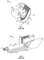
- Figure 1 is a perspective view of a known power splice terminal which is to be loaded with multiple wires.
- Figure 2 is a perspective view of the terminal shown in Figure 1 with a lead wire and magnet wires loaded therein.
- Figure 3 is a perspective view of a wire presentation device formed in accordance with an embodiment of the present invention for loading wires into the terminal shown in Figure 1.
- Figure 4 is an exploded perspective view of the wire presentation device shown in Figure 3.
- Figure 5 is a cross sectional view of the wire presentation device taken along line 5-5 of Figure 3.
- Figure 6 is a side elevational schematic view of a terminal crimping station utilizing the magnet wire presentation device shown in Figures 3-5 in a loading position.
- Figure 7 is a side elevational schematic view of the terminal crimping station shown in Figure 6 in a crimping position.
- Figure 1 is a perspective view of a known power splice terminal 10. While the invention is described with respect to a power splice terminal, it is contemplated that the invention may be used with other types of terminals that receive multiple wires. A power splice terminal 10 is therefore described and illustrated herein for illustrative purposes only, and the invention is not intended to be restricted to any particular terminal configuration, such as the power splice terminal 10.
- Power splice terminal 10 is integrally formed from a conductive material into a lower channel section, sometimes referred to as a lower saddle 12, and an upper channel section, sometimes referred to as an upper saddle 14.
- the lower saddle 12 includes a bottom wall 16 and opposite side walls 18 and 20 extending from the bottom wall 16 at an obtuse angle thereto.
- the upper saddle 14 extends from one of the side walls 20 of the lower saddle 12, and the upper saddle 14 also includes a bottom wall 22 and opposite side walls 24 and 26 extending at an angle from the bottom wall 22.
- One side wall 26 of the upper saddle 14 extends continuously from one of the side walls 20 of the lower saddle 12.
- the other side walls 18, and 24 of the respective lower and upper saddles 12 and 14 are separated from one another by a specified distance, thereby forming a gap 28 therebetween. Additionally, the bottom wall 22 of the upper saddle 14 and the bottom wall 16 of the lower saddle 12 are separated by a predetermined distance to form a gap 30 therebetween.
- Power splice terminal 10 is known as an "Open Barrel Pigtail" terminal, and is commercially available, for example, from Tyco Electronics Corporation.
- the lower saddle 12 receives a number of magnet wires (not shown in Figure 1) in gaps 28 and 30 and the upper saddle 14 receives a lead wire (not shown in Figure 1) as explained below.
- the lower saddle 12 includes serrations 32 on an inner surface 34 thereof to pierce through insulation on the magnet wires loaded into the lower saddle 12 when the power splice terminal 10 is crimped, as also described further below.
- FIG 2 is a perspective view of the power splice terminal 10 illustrating a lead wire 40 loaded into the upper saddle 14 and a number of magnet wires 42 loaded into the lower saddle 12.
- the lead wire 40 includes a number of conductors 44 surrounded by an insulation sheath 46.
- the insulation sheath 46 is stripped from the lead wire 40 proximate the upper saddle 14 so that when the power splice terminal 10 is crimped an electrical connection is established between the conductors 44 and the upper saddle 14. In the crimping process, the upper saddle 14 is bent about the stripped lead wire 40.
- the magnet wires 42 are inserted into the lower saddle 12 through the gap 28 between the lower and upper saddles 12 and 14 along one side thereof and are fitted into the gap 30 between bottom walls 16 and 22 the lower saddle 12 and the upper saddle 14.
- the magnet wires 42 also include an outer layer or layers of insulation, enamel coatings, etc.
- the serrations 32 on the lower saddle 12 pierce through the insulation and coatings on the magnet wire 42 to contact conductive portions of the magnet wire 42 when the power splice terminal 10 is crimped. During the crimping process, the lower saddle 12 is bent to securely retain the magnet wires 42 and to close the gaps 28 and 30 between the lower and upper saddles 12 and 14.
- the lead wire 40 is coupled to a power supply (not shown), and current flows from the lead wire 40 to the upper saddle 14.
- the current flows from the upper saddle 14 to the lower saddle 12, and ultimately to the magnet wires 42 which may for example, form a coil winding in an electrical device (not shown).
- eight magnet wires 42 and a lead wire 40 must be loaded into the power splice terminal 10 by a single operator, and the power splice terminal 10 is crimped automatically by a machine in a terminal crimping station (described below). Managing the wires 40 and 42 during the loading and crimping process by a single operator is a challenging task.
- the power splice terminals 10 can only be crimped as fast as the power splice terminals 10 can be loaded with the lead wire 40 and the magnet wires 42. Thus, if the wires 40 and 42 cannot be efficiently loaded into the power splice terminal 10, manufacturing operations of an electrical device including the power splice terminals 10 are negatively impacted. Further, if the wires 40 and 42 are not properly loaded, the reliability of the electrical connection through the power splice terminal 10 may be compromised, and the operability of the associated electrical device may also be compromised.
- FIG 3 is a perspective view of a wire presentation device 60 to facilitate loading of wires into the power splice terminal 10 (shown in Figures 1 and 2) for improved crimping operations and reliability.
- the wire presentation device 60 includes a left guard wall 62, a right guard wall 64, a front guard wall 66, and a top guard wall 68.
- Mounting brackets 70, 72 extend from each respective left and right guard walls 62, 64 so that the wire presentation device may be installed to an automatic crimping station (described below).
- the guard walls 62-68 provide a safety barrier around the crimping zone in the crimping station when the wire presentation device 60 is installed.
- Each of the left and right guard walls 62 and 64 include a respective guide slot 74 and 76.
- the guide slots 74 and 76 each extend from a leading edge 78 and 80 of the respective left and right guard walls 62 and 64, and the guide slots 74 and 76 extend along a curved path toward a center of the left and right guard walls 62 and 64.
- the front and top guard walls 66 and 68 are separated from one another along the leading edges 78 and 80 of the left and right guard walls 62, 64 in the vicinity of the guide slots 74 and 76.
- the left and right guard walls 62 and 64 and the front and top guard walls 66 and 68 thereby form a guide opening 82 extending across the front of the wire presentation device 60 between the guide slots 74 and 76.
- Guide members 84 and 86 are suspended between the left and right guard walls 62 and 64 on either side of the guide slots 74 and 76 and also on either side of the guide opening 82.
- the guide members 84 and 86 funnel wire, such as wires 42 (shown in Figure 2), to the lower saddle 12 of a power splice terminal 10 when the wire is inserted into the guide slots 74 and 76, as explained further below.
- Adjusting screws 88 and 90 are provided on each respective front guard wall 66 and the top guard wall 68. The adjusting screws 88 and 90 position the guide members 84 and 86 relative to the guide slots 74 and 76 to accommodate different sizes and numbers of magnet wires 42 (shown in Figure 2).
- the device 60 may also be used to guide a lead wire 40 (shown in Figure 2) into the upper saddle 14 of a power splice terminal 10.
- FIG 4 is an exploded perspective view of the wire presentation device 60.
- the guide members 84 and 86 are suspended between the left and right guards walls 62 and 64 on cylindrical shafts 100 and 102 which extend through respective apertures 106 and 108 in each of the left guard wall 62 and the right guard wall 64.
- the shafts 100 and 102 are fastened the left and right guard walls 62 and 64 with retaining clips 109.
- Each of the guide members 84 and 86 includes a respective head section 110 and 112 including a bore 114 and 116 through which the respective shaft 100 and 102 extends, thereby facilitating a rotational or swinging movement of the head sections about the shafts 100 and 102.
- the guide members 84 and 86 further include respective fin sections 118 and 120 extending from the head sections 110 and 112, and the fin sections 118 and 120 are curved to facilitate placement of the magnet wires 42 (shown in Figure 2) between the fin sections 118 and 120.
- Torsion spring elements 122 and 124 are provided on each of the shafts 100 and 102, and the spring elements 122 and 124 interface with a respective flat 126 and 128 extending from one end of each of the head sections 110 and 112 of the guide members 84 and 86.
- the torsion spring elements 122 and 124 bias the guide members 84 and 86 in a loading position for loading of wire, but permit the guide members 84 and 86 to be positioned away from the power splice terminal 10 in a crimping position explained below.
- Positioning members in the form of the adjusting screws 88 and 90 extend through the front guard wall 66 and the top guard wall 68, and flats 130 and 132 are provided in the center of each of the head sections 110 and 112 of the guide members 84 and 86.
- the adjusting screws 88 and 90 engage the flats 130 and 132 to position the guide members 84 and 86 in a desired orientation relative to the left and right guard walls 62 and 64, and more specifically with respect to the guide slots 74 and 76.
- the front guard wall 66 is coupled to the left and right guard walls 62 and 64 with screws 134
- the top guard wall 68 is attached to the left and right guards 62 and 64 with screws 136. It is recognized, however, that other attachment members and schemes could be employed in lieu of screws 134 and 136 in alternative embodiments of the invention to assemble the guard walls 62-68. Additionally, it is contemplated that one or more of the guard walls 62-68 may be formed together in alternative embodiments to reduce the number of components to assemble
- the top guard wall 68 includes a tapered front end 138.
- the tapered front end 138 forms a guide surface 140 extending between the leading edges 78 and 80 of the left and right guard walls 62 and 64 when the wire presentation device 60 is assembled.
- FIG 5 is a cross sectional view of the wire presentation device 60 illustrating guide members 84 and 86 in position for loading of magnet wires 42 (shown in Figure 2).
- Each of the fin sections 118 and 120 includes a respective guide surface 150, 152 extending into the guide slots 74 and 76 of the left and right guard walls 62 and 64.
- the guide surfaces 150 and 152 funnels the wire into a power splice terminal 10 (shown in Figures 1 and 2) located at the ends of the fin sections 118 and 120 of the guide members 84 and 86.
- the distance that the guide members 84 and 86 extends into the guide slots 74 and 76 can be increased or decreased to accommodate different sizes of wires.
- the distance between the guide members 84 and 86 can be increased or decreased by manipulating the adjust screws 88 and 90 so that larger or smaller wires may be inserted between the guide members 84 and 86..
- one of the guide surfaces 150 is concave and the other guide surface 152 is convex, and the guide surfaces 150 and 152 are located proximal to the curved guide slots 74 and 76. It is recognized, however, that other configurations of guide surfaces 150 and 152 may be employed in conjunction with the same or differently shaped guide slots 74 and 76 in various alternative embodiments of the invention.
- FIG 6 is a side elevational schematic view of a terminal crimping station 160 illustrating the wire presentation device 60 in a loading position and with the guide walls 62-68 (shown in Figures 2-5) removed for clarity.
- the terminal crimping station 160 includes an applicator 161 having a base 162 and a ram assembly 164.
- the ram assembly 164 includes a crimper 168, and the ram assembly is reciprocally movable toward and away from the base 162.
- the ram assembly 164 is driven by a press machine (not shown) to crimp power splice terminals 10 situated between the left and right guard walls 62 and 64 in the wire presentation device 60.
- the guide members 84 and 86 are positioned relative to one of the power splice terminals 10 in the terminal crimping station 160 so that when a wire is inserted between the guide members 84 and 86, the guide members 84 and 86 direct the wire into the power splice terminal 10, or more specifically into the lower saddle 12 (shown in Figures 1 and 2).
- Figure 7 is a side elevational schematic view of the terminal crimping station 160 illustrating the wire presentation device 60 in a crimping position and with the guide walls 62-68 (shown in Figures 2-5) removed for clarity.
- the ram assembly 164 is descended onto the base 162 such that the crimper 168 contacts the power splice terminal 10 in the crimping position.
- the ram assembly 164 contacts the guide member 84 as it descends toward the base 162 and pivots the guide member 84 against the bias of the spring element 122 (shown in Figure 4) away from the path of the ram assembly 164.
- the guide member 84 in turns, contacts the guide member 86 and pivots the guide member 86 away from the path of the ram assembly 164 against the bias of spring element 124 (shown in Figure 4).
- both the guide members 84 and 86 are pivoted about the respective shafts 100 and 102 to a position alongside the ram assembly 164 and away from the power splice terminal 10 where the guide members 84 and 86 do not interfere with the crimping of the power splice terminal 10.
- the ram assembly 164 ascends away from the base 162 and the guide members are released by the ram assembly 164. Once released, the spring elements 122 and 124 return to the loading position shown in Figure 6.
- another power splice terminal 10 may be loaded with wires using the guide members 84 and 86 and the crimping process may be repeated.
- the wire presentation device 60 by virtue of the guide members 84 and 86, promotes efficient and accurate loading of the power splice terminals 10 with wires. Loading of the terminals is simplified and operator error in the crimping operation is reduced. Reliable terminal connections are therefore established in an efficient crimping process.
Landscapes
- Engineering & Computer Science (AREA)
- Manufacturing & Machinery (AREA)
- Manufacturing Of Electrical Connectors (AREA)
Abstract
A wire presentation device (60) for a terminal including a saddle
includes at least one guard wall (62,64), and at least one guide member (84,86)
rotatably mounted to the guard wall (62,64) and positionable between a loading
position and a crimping position. The guide member (84,86) is configured to funnel
wire into the saddle of the terminal in the loading position. The guard wall (62,64)
includes a curved guide slot (74,76) therein, the at least one guide member (84,86)
extends proximate the slot (74,76). A spring element (122,124) biases the guide
member (84,86) in the loading position and a position of the guide member (84,86)
relative to the guard wall (62,64) is adjustable. The guide member (84,86) has a
contoured outer surface, and the outer surface has a flat section (126,128) therein for
accommodating an adjustable positioning member (88,90). The guide member
(84,86) is configured to be positioned away from the terminal when in the crimping
position.
Description
- The invention relates generally to power splice terminals for coil winding applications, and more specifically, to a wire presentation device to facilitate loading of wires into a power splice terminal.
- Magnet wires are used to form coil windings for a variety of electrical devices. When energized, the coil windings generate magnetic fields and electromagnetic forces to drive, for example, a rotor of an electric motor. When the magnet wire is installed into a stator structure of the motor, the windings cause the rotor to rotate when the stator windings are energized. To supply power to the windings, power splice terminals are sometimes employed to couple a power lead wire to the magnet wires.
- One type of power splice terminal includes an upper saddle which accepts a lead wire or lead wires, and a lower saddle which accepts a number of magnet wires used in the coil windings. When the lead wires and the magnet wires are loaded into the respective upper and lower saddles of the terminal, the terminal is crimped or bent to secure the wires to the terminal. The lower saddle includes serrations formed therein which pierce the insulation of the magnet wires to establish electrical connection to the terminal in the lower saddle when the terminal is crimped. The lead wires are crimped in the upper saddle to establish electrical connection of the lead wire to the terminal. Electrical connections of the lead wires and the magnet wires through the terminal are therefore established.
- Loading the wires into the terminal, however, is problematic. For instance, in some applications eight magnet wires may be loaded into the lower saddle of an open barrel pigtail terminal. Positioning this many magnet wires efficiently and correctly into the lower saddle of the terminal can be challenging. If the magnet wires are not positioned properly, the electrical connection through the terminal may be compromised, and the associated electrical device may not function properly.
- In accordance with an exemplary embodiment, a wire presentation device for a terminal including a saddle is provided. The wire presentation device comprises at least one guard wall, and at least one guide member rotatably mounted to the guard wall and positionable between a loading position and a crimping position. The guide member is configured to funnel wire into the saddle of the terminal in the loading position.
- Optionally, the guard wall includes a curved guide slot therein, the at least one guide member extends proximate the slot. A spring element biases the guide member in the loading position and a position of the guide member relative to the guard wall is adjustable. The guide member includes a head section and a fin section extending from the head section. The guide member has a contoured outer surface, and the outer surface has a flat section therein for accommodating an adjustable positioning member. The guide member is configured to be positioned away from the terminal when in the crimping position.
- In another exemplary embodiment of the invention, a wire presentation device for a power splice terminal including a saddle is provided. The wire presentation device comprises first and second guard walls extending substantially parallel to one another and separated by a distance to contain the terminal therebetween. At least one guide member is suspended between the first guard wall and the second guard wall, and the guide member being configured to funnel wire into the saddle of the terminal when the terminal is located between the first guard and the second guard. The guide member is positionable away from the terminal when the terminal is crimped.
- In another exemplary embodiment of the invention, a wire presentation device for a power splice terminal including an upper saddle for accepting a lead wire and a lower saddle for accepting a magnet wire is provided. The wire presentation device comprises first and second guard walls extending substantially parallel to one another and separated by a distance to contain the terminal therebetween. A pair of guide members suspended between the first guard wall and the second guard wall are separated by an adjustable distance from one another. The pair of guide members are configured to funnel wire into the lower saddle of the terminal when the terminal is located between the first guard wall and the second guard wall, and the pair of guides members are positionable away from the terminal when the terminal is crimped.
- An embodiment of the present invention will now be described by way of example with reference to the accompanying drawings, in which:
- Figure 1 is a perspective view of a known power splice terminal which is to be loaded with multiple wires.
- Figure 2 is a perspective view of the terminal shown in Figure 1 with a lead wire and magnet wires loaded therein.
- Figure 3 is a perspective view of a wire presentation device formed in accordance with an embodiment of the present invention for loading wires into the terminal shown in Figure 1.
- Figure 4 is an exploded perspective view of the wire presentation device shown in Figure 3.
- Figure 5 is a cross sectional view of the wire presentation device taken along line 5-5 of Figure 3.
- Figure 6 is a side elevational schematic view of a terminal crimping station utilizing the magnet wire presentation device shown in Figures 3-5 in a loading position.
- Figure 7 is a side elevational schematic view of the terminal crimping station shown in Figure 6 in a crimping position.
- Figure 1 is a perspective view of a known
power splice terminal 10. While the invention is described with respect to a power splice terminal, it is contemplated that the invention may be used with other types of terminals that receive multiple wires. Apower splice terminal 10 is therefore described and illustrated herein for illustrative purposes only, and the invention is not intended to be restricted to any particular terminal configuration, such as thepower splice terminal 10. -
Power splice terminal 10 is integrally formed from a conductive material into a lower channel section, sometimes referred to as alower saddle 12, and an upper channel section, sometimes referred to as anupper saddle 14. Thelower saddle 12 includes abottom wall 16 andopposite side walls bottom wall 16 at an obtuse angle thereto. Theupper saddle 14 extends from one of theside walls 20 of thelower saddle 12, and theupper saddle 14 also includes abottom wall 22 andopposite side walls bottom wall 22. Oneside wall 26 of theupper saddle 14 extends continuously from one of theside walls 20 of thelower saddle 12. Theother side walls upper saddles gap 28 therebetween. Additionally, thebottom wall 22 of theupper saddle 14 and thebottom wall 16 of thelower saddle 12 are separated by a predetermined distance to form agap 30 therebetween. -
Power splice terminal 10 is known as an "Open Barrel Pigtail" terminal, and is commercially available, for example, from Tyco Electronics Corporation. In use, thelower saddle 12 receives a number of magnet wires (not shown in Figure 1) ingaps upper saddle 14 receives a lead wire (not shown in Figure 1) as explained below. Thelower saddle 12 includesserrations 32 on aninner surface 34 thereof to pierce through insulation on the magnet wires loaded into thelower saddle 12 when thepower splice terminal 10 is crimped, as also described further below. - Figure 2 is a perspective view of the
power splice terminal 10 illustrating alead wire 40 loaded into theupper saddle 14 and a number ofmagnet wires 42 loaded into thelower saddle 12. Thelead wire 40 includes a number ofconductors 44 surrounded by aninsulation sheath 46. Theinsulation sheath 46 is stripped from thelead wire 40 proximate theupper saddle 14 so that when thepower splice terminal 10 is crimped an electrical connection is established between theconductors 44 and theupper saddle 14. In the crimping process, theupper saddle 14 is bent about the strippedlead wire 40. - The
magnet wires 42 are inserted into thelower saddle 12 through thegap 28 between the lower andupper saddles gap 30 betweenbottom walls lower saddle 12 and theupper saddle 14. Themagnet wires 42 also include an outer layer or layers of insulation, enamel coatings, etc. Theserrations 32 on thelower saddle 12 pierce through the insulation and coatings on themagnet wire 42 to contact conductive portions of themagnet wire 42 when thepower splice terminal 10 is crimped. During the crimping process, thelower saddle 12 is bent to securely retain themagnet wires 42 and to close thegaps upper saddles - After crimping the
power splice terminal 10, thelead wire 40 is coupled to a power supply (not shown), and current flows from thelead wire 40 to theupper saddle 14. The current flows from theupper saddle 14 to thelower saddle 12, and ultimately to themagnet wires 42 which may for example, form a coil winding in an electrical device (not shown). In at least some applications, eightmagnet wires 42 and alead wire 40 must be loaded into thepower splice terminal 10 by a single operator, and thepower splice terminal 10 is crimped automatically by a machine in a terminal crimping station (described below). Managing thewires power splice terminals 10 can only be crimped as fast as thepower splice terminals 10 can be loaded with thelead wire 40 and themagnet wires 42. Thus, if thewires power splice terminal 10, manufacturing operations of an electrical device including thepower splice terminals 10 are negatively impacted. Further, if thewires power splice terminal 10 may be compromised, and the operability of the associated electrical device may also be compromised. - Figure 3 is a perspective view of a
wire presentation device 60 to facilitate loading of wires into the power splice terminal 10 (shown in Figures 1 and 2) for improved crimping operations and reliability. Thewire presentation device 60 includes aleft guard wall 62, aright guard wall 64, afront guard wall 66, and atop guard wall 68. Mountingbrackets right guard walls wire presentation device 60 is installed. - Each of the left and
right guard walls respective guide slot guide slots edge right guard walls guide slots right guard walls top guard walls edges right guard walls guide slots right guard walls top guard walls guide opening 82 extending across the front of thewire presentation device 60 between theguide slots -
Guide members right guard walls guide slots guide opening 82. Theguide members lower saddle 12 of apower splice terminal 10 when the wire is inserted into theguide slots screws front guard wall 66 and thetop guard wall 68. The adjusting screws 88 and 90 position theguide members guide slots device 60 may also be used to guide a lead wire 40 (shown in Figure 2) into theupper saddle 14 of apower splice terminal 10. - Figure 4 is an exploded perspective view of the
wire presentation device 60. Theguide members right guards walls cylindrical shafts respective apertures left guard wall 62 and theright guard wall 64. Theshafts right guard walls clips 109. Each of theguide members respective head section 110 and 112 including abore respective shaft shafts guide members respective fin sections head sections 110 and 112, and thefin sections fin sections -
Torsion spring elements shafts spring elements head sections 110 and 112 of theguide members torsion spring elements guide members guide members power splice terminal 10 in a crimping position explained below. Positioning members in the form of the adjusting screws 88 and 90 extend through thefront guard wall 66 and thetop guard wall 68, andflats head sections 110 and 112 of theguide members flats guide members right guard walls guide slots - The
front guard wall 66 is coupled to the left andright guard walls screws 134, and thetop guard wall 68 is attached to the left andright guards screws 136. It is recognized, however, that other attachment members and schemes could be employed in lieu ofscrews - The
top guard wall 68 includes a taperedfront end 138. The taperedfront end 138 forms aguide surface 140 extending between theleading edges right guard walls wire presentation device 60 is assembled. - Figure 5 is a cross sectional view of the
wire presentation device 60 illustratingguide members fin sections respective guide surface guide slots right guard walls wire presentation device 60 between theguide slots guide members fin sections guide members screws guide members guide slots guide members screws guide members - As illustrated in Figure 5, one of the guide surfaces 150 is concave and the
other guide surface 152 is convex, and the guide surfaces 150 and 152 are located proximal to thecurved guide slots guide slots - Figure 6 is a side elevational schematic view of a
terminal crimping station 160 illustrating thewire presentation device 60 in a loading position and with the guide walls 62-68 (shown in Figures 2-5) removed for clarity. Theterminal crimping station 160 includes anapplicator 161 having a base 162 and aram assembly 164. Theram assembly 164 includes acrimper 168, and the ram assembly is reciprocally movable toward and away from thebase 162. Theram assembly 164 is driven by a press machine (not shown) to crimppower splice terminals 10 situated between the left andright guard walls wire presentation device 60. - The
guide members power splice terminals 10 in theterminal crimping station 160 so that when a wire is inserted between theguide members guide members power splice terminal 10, or more specifically into the lower saddle 12 (shown in Figures 1 and 2). - Figure 7 is a side elevational schematic view of the
terminal crimping station 160 illustrating thewire presentation device 60 in a crimping position and with the guide walls 62-68 (shown in Figures 2-5) removed for clarity. When thewires 40 and 42 (shown in Figure 1) are properly loaded into thepower splice terminal 10 beneath theguide members ram assembly 164 is descended onto the base 162 such that thecrimper 168 contacts thepower splice terminal 10 in the crimping position. Theram assembly 164 contacts theguide member 84 as it descends toward thebase 162 and pivots theguide member 84 against the bias of the spring element 122 (shown in Figure 4) away from the path of theram assembly 164. Theguide member 84, in turns, contacts theguide member 86 and pivots theguide member 86 away from the path of theram assembly 164 against the bias of spring element 124 (shown in Figure 4). In the crimping position, both theguide members respective shafts ram assembly 164 and away from thepower splice terminal 10 where theguide members power splice terminal 10. - Once the
power splice terminal 10 is crimped, theram assembly 164 ascends away from thebase 162 and the guide members are released by theram assembly 164. Once released, thespring elements power splice terminal 10 is positioned into thewire presentation device 60, anotherpower splice terminal 10 may be loaded with wires using theguide members - The
wire presentation device 60, by virtue of theguide members power splice terminals 10 with wires. Loading of the terminals is simplified and operator error in the crimping operation is reduced. Reliable terminal connections are therefore established in an efficient crimping process. - While the invention has been described in terms of various specific embodiments, those skilled in the art will recognize that the invention can be practiced with modification within the scope of the claims.
Claims (20)
- A wire presentation device (60) for a terminal (10) including a saddle (12), said wire presentation device (60) comprising:at least one guard wall (62,64); andat least one guide member (84,86) rotatably mounted to said guard wall (62,64) and positionable between a loading position and a crimping position, said guide member (84,86) being configured to funnel wire (42) into the saddle (12) of the terminal (10) in the loading position.
- A wire presentation device (60) in accordance with claim 2 wherein said guard wall (62,64) includes a curved guide slot (74,76) therein, said at least one guide member (84,86) extending proximate said slot (74,76).
- A wire presentation device (60) in accordance with claim 1 or claim 2 further comprising a spring element (122,124), said spring element (122,124) biasing said guide member (84,86) in the loading position.
- A wire presentation device (60) in accordance with claim 1, 2 or 3 wherein a position of said guide member (84,86) relative to said guard wall (62,64) is adjustable.
- A wire presentation device (60) in accordance with any preceding claim wherein said at least one guide member comprises an upper guide member (84) and a lower guide member (86), a position of at least one of said upper guide member (84) and said lower guide member (86) being adjustable relative to said guard wall (62,64).
- A wire presentation device (60) in accordance with any preceding claim wherein said guide member (84,86) includes a head section (110,112) and a fin section (118,120) extending from said head section (110,112).
- A wire presentation device (60) in accordance with any preceding claim, wherein said at least one guide member comprises an upper guide member (84) and a lower guide member (86), each of said upper and lower guide members (84,86) having a contoured guide surface (150,152), one of said guide surfaces (152) being convex and one of said guide surfaces (150) being concave.
- A wire presentation device (60) in accordance with any preceding claim, wherein said guide member has a contoured outer surface, said outer surface having a flat section (126,128) therein for accommodating an adjustable positioning member (88,90).
- A wire presentation device (60) in accordance with any preceding claim wherein said guide member (84,86) is configured to be positioned away from said terminal (10) when in the crimping position.
- A wire presentation device (60) for a power splice terminal (10) including a saddle (12), said wire presentation device (60) comprising:first and second guard walls (62,64) extending substantially parallel to one another and separated by a distance to contain the terminal (10) therebetween; andat least one guide member (84,86) suspended between said first guard wall (62) and said second guard wall (64), said guide member (84,86) being configured to funnel wire (42) into the saddle (12) of the terminal (10) when the terminal (10) is located between the first guard wall (62) and the second guard wall (64), said guide member (84,86) being positionable away from said terminal (10) when the terminal (10) is crimped.
- A wire presentation device (60) in accordance with claim 10 wherein each of said first and second guard walls (62,64) include a guide slot (74,76) therein, said guide member (84,86) located proximate to said guide slot (74,76).
- A wire presentation device (60) in accordance with claim 10 or 11 wherein a position of said guide member (84,86) relative to said first guard wall (62) and second guard wall (64) is adjustable to accommodate various diameters of magnet wire (42).
- A wire presentation device (60) in accordance with claim 10, 11 or 12 further comprising a front guard wall (66) and a top guard wall (68) extending between said first guard wall (62) and said second guard wall (64), said front guard wall (66) and said top guard wall (68) defining an opening (82) leading to said guide member (84,86).
- A wire presentation device (60) in accordance with any one of claims 10 to 13 wherein said guide member (84,86) includes a head section (110,112) and a fin section (118,120) extending from said head section (110,112).
- A wire presentation device (60) in accordance with any one of claims 10 to 14, wherein said guide member (84,86) has a contoured guide surface (150,152), said first and second guard walls (62,64) including guide slots (74,76) therein, said contoured guide surface (150,152) extending into said slots (74,76).
- A wire presentation device (60) in accordance with any one of claims 10 to 15, said device (60) including an upper guide member (84) and a lower guide member (86), each of said upper guide member (84) and lower guide member (86) having a contoured outer surface, said outer surface having a flat section (126,128) therein for accommodating an adjustable positioning member (88,90).
- A wire presentation device (60) for a power splice terminal (10) including an upper saddle (14) for accepting a lead wire (40) and a lower saddle (12) for accepting a magnet wire (42), said wire presentation device (60) comprising:first and second guard walls (62,64) extending substantially parallel to one another and separated by a distance to contain the terminal (10) therebetween; anda pair of guide members (84,86) suspended between said first guard wall (62) and said second guard wall (64) and separated by an adjustable distance from one another, said pair of guide members (84,86) being configured to funnel wire (42) into the lower saddle (12) of the terminal (10) when the terminal (10) is located between the first guard wall (62) and the second guard wall (64), said pair of guides members (84,86) being positionable away from said terminal (10) when the terminal (10) is crimped.
- A wire presentation device (60) in accordance with claim 17 wherein each of said first and second guard walls (62,64) includes a guide slot (74,76) therein, said first and second guide members (84,86) located on opposite sides of said guide slot (74,76).
- A wire presentation device (60) in accordance with claim 17 or 18 further comprising a front guard wall (66) and a top guard wall (68) extending between said first and second guard walls (62,64), said front guard wall (66) and said top guard wall (68) defining an opening (82) leading to said guide members (84,86).
- A wire presentation device (60) in accordance with claim 17, 18 or 19 wherein said guide members (84,86) comprise a head section (110,112) and a contoured fin section (118,120) extending from said head section (110,112).
Applications Claiming Priority (2)
| Application Number | Priority Date | Filing Date | Title |
|---|---|---|---|
| US440627 | 2003-05-19 | ||
| US10/440,627 US6779254B1 (en) | 2003-05-19 | 2003-05-19 | Wire presentation device for power splice terminal |
Publications (1)
| Publication Number | Publication Date |
|---|---|
| EP1480297A1 true EP1480297A1 (en) | 2004-11-24 |
Family
ID=32869286
Family Applications (1)
| Application Number | Title | Priority Date | Filing Date |
|---|---|---|---|
| EP04252876A Withdrawn EP1480297A1 (en) | 2003-05-19 | 2004-05-18 | Wire presentation device for power splice terminal |
Country Status (3)
| Country | Link |
|---|---|
| US (1) | US6779254B1 (en) |
| EP (1) | EP1480297A1 (en) |
| JP (1) | JP2004349255A (en) |
Families Citing this family (3)
| Publication number | Priority date | Publication date | Assignee | Title |
|---|---|---|---|---|
| US8076813B2 (en) * | 2006-06-21 | 2011-12-13 | Emerson Electric Co. | Hermetic motors with windings coupled to on-winding motor protectors via welded terminals |
| US10637163B2 (en) * | 2018-05-25 | 2020-04-28 | Te Connectivity Corporation | Magnet wire splice terminal |
| US20230122329A1 (en) * | 2021-10-18 | 2023-04-20 | Abb Schweiz Ag | Linearized magnet wire connector |
Citations (1)
| Publication number | Priority date | Publication date | Assignee | Title |
|---|---|---|---|---|
| DE3910764A1 (en) * | 1989-04-04 | 1990-10-11 | Licentia Gmbh | Pin-setting machine for connecting two cables to a common fitting |
Family Cites Families (3)
| Publication number | Priority date | Publication date | Assignee | Title |
|---|---|---|---|---|
| US3693230A (en) * | 1970-12-18 | 1972-09-26 | Itt | Wire guide |
| CA1063783A (en) * | 1975-11-03 | 1979-10-09 | James W. Hammond | Wire feeding apparatus |
| US5626152A (en) * | 1992-08-26 | 1997-05-06 | Molins Plc | Cigarette making machine |
-
2003
- 2003-05-19 US US10/440,627 patent/US6779254B1/en not_active Expired - Fee Related
-
2004
- 2004-05-18 EP EP04252876A patent/EP1480297A1/en not_active Withdrawn
- 2004-05-19 JP JP2004148927A patent/JP2004349255A/en active Pending
Patent Citations (1)
| Publication number | Priority date | Publication date | Assignee | Title |
|---|---|---|---|---|
| DE3910764A1 (en) * | 1989-04-04 | 1990-10-11 | Licentia Gmbh | Pin-setting machine for connecting two cables to a common fitting |
Also Published As
| Publication number | Publication date |
|---|---|
| US6779254B1 (en) | 2004-08-24 |
| JP2004349255A (en) | 2004-12-09 |
Similar Documents
| Publication | Publication Date | Title |
|---|---|---|
| EP0106444B1 (en) | Termination for electrical armature winding | |
| US5648695A (en) | Brush apparatus for electric rotating machine | |
| JP2899300B2 (en) | Method and apparatus for manufacturing electric harness | |
| US8025522B2 (en) | Insulation displacement connector | |
| EP3716416A1 (en) | Electrical cable assembly, method and apparatus for making same and electrical terminal for same | |
| JPH07192778A (en) | Insulation-cut electrical connector with improved strain relief | |
| GB2264811A (en) | Stator construction/winding connections in an electric motor | |
| US7462081B2 (en) | Connection terminal and stator having distributor unit utilizing same | |
| CN1021679C (en) | Armature | |
| CA3011112A1 (en) | Assembly procedure for a long-stator linear motor | |
| EP0282670B1 (en) | An armature for an electric motor | |
| US6779254B1 (en) | Wire presentation device for power splice terminal | |
| EP0271175B1 (en) | A commutator | |
| US10637163B2 (en) | Magnet wire splice terminal | |
| CN103368305B (en) | Motor structure | |
| EP1115191B1 (en) | Connection assembly particularly for the windings of a stator of an electric motor | |
| US11865692B2 (en) | Magnetic base | |
| EP0350193A2 (en) | An armature | |
| JP7482832B2 (en) | Stranded wire connection tool | |
| GB2223888A (en) | Assembled commutator for electric motor | |
| US7007381B2 (en) | Method of attaching an electric conductor to an electrically conductive terminal via a telescoping sleeve | |
| JP7423153B2 (en) | Wiring machine | |
| JP3440811B2 (en) | Transmission line position displacement prevention device | |
| EP1398862A2 (en) | Connection terminal for the windings of a stator of an electric motor | |
| EP4254742A1 (en) | Electric machine |
Legal Events
| Date | Code | Title | Description |
|---|---|---|---|
| PUAI | Public reference made under article 153(3) epc to a published international application that has entered the european phase |
Free format text: ORIGINAL CODE: 0009012 |
|
| AK | Designated contracting states |
Kind code of ref document: A1 Designated state(s): AT BE BG CH CY CZ DE DK EE ES FI FR GB GR HU IE IT LI LU MC NL PL PT RO SE SI SK TR |
|
| AX | Request for extension of the european patent |
Extension state: AL HR LT LV MK |
|
| AKX | Designation fees paid | ||
| REG | Reference to a national code |
Ref country code: DE Ref legal event code: 8566 |
|
| STAA | Information on the status of an ep patent application or granted ep patent |
Free format text: STATUS: THE APPLICATION IS DEEMED TO BE WITHDRAWN |
|
| 18D | Application deemed to be withdrawn |
Effective date: 20050525 |