EP1480285A2 - Membrane electrode assembly for polymer electrolyte fuel cell - Google Patents
Membrane electrode assembly for polymer electrolyte fuel cell Download PDFInfo
- Publication number
- EP1480285A2 EP1480285A2 EP04011318A EP04011318A EP1480285A2 EP 1480285 A2 EP1480285 A2 EP 1480285A2 EP 04011318 A EP04011318 A EP 04011318A EP 04011318 A EP04011318 A EP 04011318A EP 1480285 A2 EP1480285 A2 EP 1480285A2
- Authority
- EP
- European Patent Office
- Prior art keywords
- layers
- carbon
- polymer electrolyte
- layer
- gas
- Prior art date
- Legal status (The legal status is an assumption and is not a legal conclusion. Google has not performed a legal analysis and makes no representation as to the accuracy of the status listed.)
- Granted
Links
Images


Classifications
-
- H—ELECTRICITY
- H01—ELECTRIC ELEMENTS
- H01M—PROCESSES OR MEANS, e.g. BATTERIES, FOR THE DIRECT CONVERSION OF CHEMICAL ENERGY INTO ELECTRICAL ENERGY
- H01M4/00—Electrodes
- H01M4/86—Inert electrodes with catalytic activity, e.g. for fuel cells
- H01M4/8605—Porous electrodes
-
- H—ELECTRICITY
- H01—ELECTRIC ELEMENTS
- H01M—PROCESSES OR MEANS, e.g. BATTERIES, FOR THE DIRECT CONVERSION OF CHEMICAL ENERGY INTO ELECTRICAL ENERGY
- H01M4/00—Electrodes
- H01M4/86—Inert electrodes with catalytic activity, e.g. for fuel cells
- H01M4/8647—Inert electrodes with catalytic activity, e.g. for fuel cells consisting of more than one material, e.g. consisting of composites
- H01M4/8657—Inert electrodes with catalytic activity, e.g. for fuel cells consisting of more than one material, e.g. consisting of composites layered
-
- H—ELECTRICITY
- H01—ELECTRIC ELEMENTS
- H01M—PROCESSES OR MEANS, e.g. BATTERIES, FOR THE DIRECT CONVERSION OF CHEMICAL ENERGY INTO ELECTRICAL ENERGY
- H01M8/00—Fuel cells; Manufacture thereof
- H01M8/10—Fuel cells with solid electrolytes
- H01M8/1004—Fuel cells with solid electrolytes characterised by membrane-electrode assemblies [MEA]
-
- Y—GENERAL TAGGING OF NEW TECHNOLOGICAL DEVELOPMENTS; GENERAL TAGGING OF CROSS-SECTIONAL TECHNOLOGIES SPANNING OVER SEVERAL SECTIONS OF THE IPC; TECHNICAL SUBJECTS COVERED BY FORMER USPC CROSS-REFERENCE ART COLLECTIONS [XRACs] AND DIGESTS
- Y02—TECHNOLOGIES OR APPLICATIONS FOR MITIGATION OR ADAPTATION AGAINST CLIMATE CHANGE
- Y02E—REDUCTION OF GREENHOUSE GAS [GHG] EMISSIONS, RELATED TO ENERGY GENERATION, TRANSMISSION OR DISTRIBUTION
- Y02E60/00—Enabling technologies; Technologies with a potential or indirect contribution to GHG emissions mitigation
- Y02E60/30—Hydrogen technology
- Y02E60/50—Fuel cells
Definitions
- the present invention relates to a membrane electrode assembly for a polymer electrolyte fuel cell.
- each of the gas-diffusion layers is constituted of carbon paper, carbon cloth or the like
- each of the electrode layers is constituted of, for example, platinum supporting carbon black and a binder (for example, see Japanese Patent Application Laid-Open No. 7-57742).
- the diameter of the carbon fiber forming carbon paper or the like is generally 8 to 10 ⁇ m, and the surface roughness of the contact surface of the gas-diffusion layer with the electrode layer becomes large, there is a fear of an increased contact resistance between the gas-diffusion layer and the electrode layer to cause reduction in the power generating performance.
- the present invention has an object to provide a membrane electrode assembly for a polymer electrolyte fuel cell capable of keeping high power generation performance by reducing the contact resistance between the gas-diffusion layer and the electrode layer.
- a membrane electrode assembly for a polymer electrolyte fuel cell having, as basic components, a polymer electrolyte membrane, a pair of electrode layers which sandwich the polymer electrolyte membrane, and a pair of gas-diffusion layers disposed outside the respective electrode layers, wherein electric medium layers are respectively provided between the electrode layer and the gas-diffusion layer at one side and between the electric layer and the gas-diffusion layer at the other side, each of the electric medium layers is constituted of a plurality of carbon whiskers, a plurality of carbon particles and a binder, and a content G W of the carbon whiskers in each of the electric medium layer is 10wt% ⁇ G W ⁇ 25wt%.
- the content G W of the carbon whiskers is set as described above and the carbon particles are used in combination in each of the electric medium layers, a large number of mutual contacts among the carbon whiskers and connections among the carbon whiskers by the carbon particles can be allowed to occur, so that the surface resistance of the electric medium layer becomes small.
- the diameter of the carbon whiskers is 0.1 to 0.2 ⁇ m, and the length of the carbon whiskers is short, so that the number of contact points of the carbon whiskers with the carbon fibers of the gas-diffusion layers and the carbon particles of the electrode layers become large. As a result, the contact resistances between the gas-diffusion layers and the electrode layers are reduced, and the power generating performance can be kept high.
- a membrane electrode assembly 1 which is used for a polymer electrolyte fuel cell has, as basic components, a polymer electrolyte membrane 2, a pair of electrode layers sandwiching the polymer electrolyte membrane 2, namely, a cathode-side electrode layer 3 and an anode-side electrode layer 4, and a pair of gas-diffusion layers 5 and 6 disposed outside the respective electrodes 3 and 4.
- electric medium layers 7 and 8 are provided respectively between the cathode-side electrode layer 3 and the gas-diffusion layer 5 and between the anode-side electrode layer 4 and the gas-diffusion layer 6.
- Each of the electric medium layers 7 and 8 are constitutedof a plurality of carbon whiskers, aplurality of carbon particles and a binder.
- a carbon whisker content G W in each of the electric medium layers 7 and 8 is set at 10wt% ⁇ G C ⁇ 25wt%
- a carbon particle content G P is set at 20wt% ⁇ G P ⁇ 50wt%
- a binder content G E is set at 20wt% ⁇ G E ⁇ 50wt%, respectively.
- the carbon particle content Gp is Gp ⁇ 20wt%
- Gp > 50wt% dispersibility of the binder becomes worse.
- the binder content G E is G E ⁇ 20 wt%
- the binder function becomes insufficient
- G E > 50 wt% the pore amount of the electric medium layers 7 and 8 becomes insufficient.
- carbon whiskers vapor phase epitaxy carbon fibers are preferable.
- the carbon whisker has a diameter of 0.1 to 0.2 ⁇ m, and has a small length, so that the number of the contact points of the carbon whiskers with the carbon fibers of the gas-diffusion layers 5 and 6 and the carbon particles of the electrode layers 3 and 4 becomes large. As a result, the contact resistances between the gas-diffusion layers 5 and 6, and the electrode layers 3 and 4 are reduced, and the power generating performance can be kept high.
- the cathode-side and the anode-side gas-diffusion layers 5 and 6 there were prepared gas-diffusion layers by diffusing and attaching FEP (fluorinated ethylene propylene) to a surface and interior, namely, the entirety of the carbon paper (made by Toray Industries, Inc., trade name TGP-H-060, 190 ⁇ m thick) to impart water repellency thereto.
- FEP fluorinated ethylene propylene
- the vapor phase epitaxy carbon fiber (made by Showa Denko K.K., Trade name VGCF) of about 0.2 ⁇ m in diameter and about 15 ⁇ m long was prepared; as the aggregate of the carbon particles, carbon black (made by Kecchen Black International Co., ltd., Trade name Kecchen Black EG600JD) was prepared; and as the binder, nafion (made by DuPont, Trade name Nafion SE) was prepared. They were measured to be in various loadings, and each compound of 12.5 g was charged into the ball mill with the NMP (N-methyl pyrolidone) solution of 0.1 L and was agitated and mixed, thereby obtaining various kinds of slurries.
- NMP N-methyl pyrolidone
- Table 1 shows the loadings (contents) of the carbon whiskers, the carbon particles, and the binder in Examples (1) to (8) of the slurry.
- Example (1) of the slurry was applied over a surface of the carbon paper constituting the cathode-side gas-diffusion layer 5 so that the dry weight is 2 mg/cm 2 , then the coating layer was dried to obtain the electric medium layer 7 integrated with the cathode side diffusion layer 5.
- the electric medium layer 8 integrated with the anode-side diffusion layer 6 was obtained by the same method as described above. These layers are called Example (1) being a unit of a two-tier laminated product.
- Examples (2) to (8) of the slurry the electric medium layers 7 integrated with the cathode-side diffusion layers 5 and the electric medium layers 8 integrated with the anode-side diffusion layers 6 were obtained in sequence. These layers are called Examples (2) to (8) being units of two-tier laminated products.
- Example (1) of the two-tier laminated product Two voltage probes were pressed against the electric medium layer 7 (or the electric medium layer 8) in Example (1) of the two-tier laminated product, namely, the surface of Example (1) of the electric medium layer 7, then DC voltage was applied between the probes, in accordance with JIS K7194, then the current which flowed at that time was measured by two current probes pressed against the surface of the electric medium layer 7, and the surface resistance was calculated from the voltage and the current.
- the surface resistances were obtained with respect to Examples (2) to (8) of the electric medium layers 7 (or the electric medium layer 8) in Examples (2) to (8) of the two-tier laminated product.
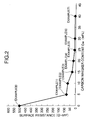
- Table 2 shows the contents G W and the surface resistances in Examples (1) to (8) of the electric medium layer 7. Electric medium layer Carbon whisker G W (wt%) Surface resistance ( ⁇ cm 2 ) Example (1) 5 80
- Example (4) 20 Example (5) 25 10
- FIG. 2 is a graph showing the relationship between the content G W and the surface resistance based on Table 2. From FIG. 2, it is understood that the surface resistance reduces with the increase in the content G W of the carbon whiskers.
- Example (1) being a unit of a three-tier laminated product.
- Examples (2) to (8) of the two-tier laminated product the electrode layer 3 which was formed on the surface of the cathode side electric medium layer 7, and the electrode layer 4 which was formed on the surface of the anode-side electric medium layer 8, were obtained in sequence by the same method as described above. They are called Examples (2) to (8) being units of three-tier laminated products.
- the cathode-side electrode layer 3 of Example (1) of the aforesaid three-tier laminated product was placed on one surface of the polymer electrolyte membrane 2 constituted of nafion (made by DuPont, trade name Nafion 112), and the anode-side electrode layer 4 of Example (1) of the aforesaid three-tier laminated product was placed on the other surface of the polymer electrolyte membrane 2, thereby forming a layered product. Then, hot press was applied to the layered product under the conditions of 140°C, 2.5 MPa, and 15 minutes, thereby obtaining Example (1) of the membrane electrode assembly. Thereafter, by using the polymer electrolyte membrane 2 as describe above and Examples (2) to (8) of the three-tier laminated product, Examples (2) to (8) of the membrane electrode assembly were obtained by the same method as described above.
- Examples (1) to (8) of the membrane electrode assembly By using Examples (1) to (8) of the membrane electrode assembly, Examples (1) to (8) of the fuel cell (cell) corresponding to them were assembled, and the critical current density was obtained with respect to them.
- the critical current density means the current density when the voltage is assumed to be zero in the I-V curve as shown in FIG. 3, and if this is large, the power generating performance is high. Thus, the following operation was performed to obtain the I-V curve.
- the resistance overvoltage Vb becomes low when the surface resistance is low in Table 2 and FIG. 2, and therefore reducing the surface resistance is effective in making the critical current density large.
- Table 3 shows the content G W of the carbon whiskers and the critical current density in Examples (1) to (8) of the fuel cell.
- the critical current densities are shown in both the case of using pure oxygen as a gas for the cathode side and the case of using air.
- FIG. 4 is a graph showing the relationship between the content of the carbon whiskers and the critical current density based on Table 3. As is obvious from Table 3 and FIG. 4, if the content G W of the carbon whiskers is set at 10wt% ⁇ G W ⁇ 25wt%, the critical current density can be made large as in Examples (2) to (5).
- the content G W of the carbon whiskers is preferably 15wt% ⁇ G W ⁇ 20wt%
- a membrane electrode assembly for a polymer electrolyte fuel cell which is capable of keeping the power generating performance high by reducing the contact resistance between the gas-diffusion layers and the electrode layers.
- a membrane electrode assembly for a polymer electrolyte fuel cell has, as basic components, a polymer electrolyte membrane, a pair of electrode layers which sandwich the polymer electrolyte membrane, and a pair of gas-diffusion layers disposed outside the respective electrode layers.
- Electric medium layers are respectively provided between the electrode layer and the gas-diffusion layer at one side and between the electric layer and the gas-diffusion layer at the other side.
- Each of the electric medium layers is constituted of a plurality of carbon whiskers, a plurality of carbon particles and a binder including an electrolyte material.
- a content G W of the carbon whiskers in each of the electric medium layers is set at 10wt% ⁇ G W ⁇ 25wt%.
Landscapes
- Chemical & Material Sciences (AREA)
- Chemical Kinetics & Catalysis (AREA)
- Electrochemistry (AREA)
- General Chemical & Material Sciences (AREA)
- Life Sciences & Earth Sciences (AREA)
- Engineering & Computer Science (AREA)
- Manufacturing & Machinery (AREA)
- Sustainable Development (AREA)
- Sustainable Energy (AREA)
- Composite Materials (AREA)
- Fuel Cell (AREA)
- Inert Electrodes (AREA)
Abstract
Description
| Slurry | Carbon whiskers GW (wt%) | Carbon particles GP (wt%) | Binder GE (wt%) |
| Example (1) | 5 | 47.5 | 47.5 |
| Example (2) | 10 | 45.0 | 45.0 |
| Example (3) | 15 | 42.5 | 42.5 |
| Example (4) | 20 | 40.0 | 40.0 |
| Example (5) | 25 | 37.5 | 37.5 |
| Example (6) | 30 | 35.0 | 35.0 |
| Example (7) | 40 | 30.0 | 30.0 |
| Example (8) | 0 | 50.0 | 50.0 |
| Electric medium layer | Carbon whisker GW (wt%) | Surface resistance (Ω·cm2) |
| Example (1) | 5 | 80 |
| Example (2) | 10 | 70 |
| Example (3) | 15 | 30 |
| Example (4) | 20 | 20 |
| Example (5) | 25 | 10 |
| Example (6) | 30 | 9 |
| Example (7) | 40 | 8 |
| Example (8) | 0 | 500 |
| Fuel cell Fuel cell | Carbon whisker GW (wt%) | Critical current density (A/g Pt) | |
| Pure oxygen | Air | ||
| Example (1) | 5 | 50 | 55 |
| Example (2) | 10 | 65 | 65 |
| Example (3) | 15 | 68 | 78 |
| Example (4) | 20 | 72 | 80 |
| Example (5) | 25 | 60 | 60 |
| Example (6) | 30 | 57 | 56 |
| Example (7) | 40 | 48 | 50 |
| Example (8) | 0 | 40 | 45 |
Claims (2)
- A membrane electrode assembly for a polymer electrolyte fuel cell having, as basic components, a polymer electrolyte membrane, a pair of electrode layers which sandwich the polymer electrolyte membrane, and a pair of gas-diffusion layers disposed outside the respective electrode layers,
wherein electric medium layers are respectively provided between the electrode layer and the gas-diffusion layer at one side and between the electric layer and the gas-diffusion layer at the other side, each of the electric medium layers is constituted of a plurality of carbon whiskers, a plurality of carbon particles and a binder, and a content GW of the carbon whiskers in each of the electric medium layer is 10wt% ≤ GW ≤ 25wt%. - The membrane electrode assembly for the polymer electrode fuel cell according to claim 1, wherein the carbon whisker is a vapor phase epitaxy carbon fiber.
Applications Claiming Priority (2)
| Application Number | Priority Date | Filing Date | Title |
|---|---|---|---|
| JP2003143046A JP4093566B2 (en) | 2003-05-21 | 2003-05-21 | Electrode structure for polymer electrolyte fuel cell |
| JP2003143046 | 2003-05-21 |
Publications (3)
| Publication Number | Publication Date |
|---|---|
| EP1480285A2 true EP1480285A2 (en) | 2004-11-24 |
| EP1480285A3 EP1480285A3 (en) | 2006-05-03 |
| EP1480285B1 EP1480285B1 (en) | 2008-08-20 |
Family
ID=33095428
Family Applications (1)
| Application Number | Title | Priority Date | Filing Date |
|---|---|---|---|
| EP04011318A Expired - Lifetime EP1480285B1 (en) | 2003-05-21 | 2004-05-12 | Membrane electrode assembly for polymer electrolyte fuel cell |
Country Status (4)
| Country | Link |
|---|---|
| US (1) | US20050008920A1 (en) |
| EP (1) | EP1480285B1 (en) |
| JP (1) | JP4093566B2 (en) |
| DE (1) | DE602004015883D1 (en) |
Cited By (1)
| Publication number | Priority date | Publication date | Assignee | Title |
|---|---|---|---|---|
| EP1670087A1 (en) * | 2004-12-02 | 2006-06-14 | Albany International Techniweave, Inc. | Control of carbon coating microcrackings in fabrication of fuel cell GDL electrode layer (s) |
Families Citing this family (5)
| Publication number | Priority date | Publication date | Assignee | Title |
|---|---|---|---|---|
| JP4203806B2 (en) * | 2003-09-30 | 2009-01-07 | トヨタ自動車株式会社 | Fuel cell simulator |
| CN101617424B (en) * | 2007-02-02 | 2012-11-28 | 旭硝子株式会社 | Process for producing membrane electrode assembly for solid polymer electrolyte fuel cell, and process for producing solid polymer electrolyte fuel cell |
| JP5277740B2 (en) * | 2008-06-10 | 2013-08-28 | 旭硝子株式会社 | Method for forming catalyst layer and method for producing membrane electrode assembly for polymer electrolyte fuel cell |
| TW201023421A (en) * | 2008-12-08 | 2010-06-16 | Ind Tech Res Inst | Binder compositions for membrane electrode assemblies and membrane electrode assemblies employing the same |
| US9853283B2 (en) | 2011-05-17 | 2017-12-26 | Indiana University Research And Technology Corporation | Rechargeable alkaline metal and alkaline earth electrodes having controlled dendritic growth and methods for making and using the same |
Family Cites Families (8)
| Publication number | Priority date | Publication date | Assignee | Title |
|---|---|---|---|---|
| US3386859A (en) * | 1964-11-04 | 1968-06-04 | Union Oil Co | Porous electrode comprising hydrophobic binder and hydrophilic material incorporated therein and method of fabricating same |
| EP1275165A1 (en) * | 2000-04-17 | 2003-01-15 | Johnson Matthey Public Limited Company | Gas diffusion substrate |
| CA2407202C (en) * | 2001-10-11 | 2009-11-03 | Honda Giken Kogyo Kabushiki Kaisha | Electrode for polymer electrolyte fuel cell |
| JP2003272671A (en) * | 2002-03-15 | 2003-09-26 | Riken Corp | Cell unit of solid polymer electrolyte fuel cell |
| US20050123816A1 (en) * | 2002-03-15 | 2005-06-09 | Yunzhi Gao | Cell unit of solid polymeric electrolyte type fuel cell |
| US7960072B2 (en) * | 2003-04-04 | 2011-06-14 | GM Global Technology Operations LLC | MEA with catalyst for oxidation of carbon monoxide |
| KR100624470B1 (en) * | 2005-06-14 | 2006-09-15 | 삼성에스디아이 주식회사 | Polymer electrolyte membrane for fuel cell and manufacturing method thereof |
| KR100738059B1 (en) * | 2006-02-08 | 2007-07-10 | 삼성에스디아이 주식회사 | Electrode for fuel cell, manufacturing method thereof and fuel cell having same |
-
2003
- 2003-05-21 JP JP2003143046A patent/JP4093566B2/en not_active Expired - Fee Related
-
2004
- 2004-05-12 EP EP04011318A patent/EP1480285B1/en not_active Expired - Lifetime
- 2004-05-12 DE DE602004015883T patent/DE602004015883D1/en not_active Expired - Lifetime
- 2004-05-13 US US10/844,583 patent/US20050008920A1/en not_active Abandoned
Cited By (1)
| Publication number | Priority date | Publication date | Assignee | Title |
|---|---|---|---|---|
| EP1670087A1 (en) * | 2004-12-02 | 2006-06-14 | Albany International Techniweave, Inc. | Control of carbon coating microcrackings in fabrication of fuel cell GDL electrode layer (s) |
Also Published As
| Publication number | Publication date |
|---|---|
| EP1480285B1 (en) | 2008-08-20 |
| EP1480285A3 (en) | 2006-05-03 |
| JP2004349048A (en) | 2004-12-09 |
| JP4093566B2 (en) | 2008-06-04 |
| DE602004015883D1 (en) | 2008-10-02 |
| US20050008920A1 (en) | 2005-01-13 |
Similar Documents
| Publication | Publication Date | Title |
|---|---|---|
| EP1489677A2 (en) | Method of making a membrane electrode assembly for electrochemical fuel cells | |
| JP5069927B2 (en) | Membrane electrode assembly for fuel cell and method for producing the same | |
| KR102472737B1 (en) | Cathode Electrode Design for Electrochemical Fuel Cells | |
| CN103181010B (en) | Electrode Catalyst for Solid Polymer Fuel Cell | |
| KR100696621B1 (en) | Electrode base material for fuel cell, manufacturing method thereof and membrane-electrode assembly comprising same | |
| JP3444530B2 (en) | Fuel cell | |
| US20220302486A1 (en) | Membrane electrode assembly | |
| CA2639636A1 (en) | Fuel cell electrode, method for producing fuel cell electrode, membrane -electrode assembly, method for producing membrane-electrode assembly, and solid polymer fuel cell | |
| US20070148531A1 (en) | Catalyst electrode, production process thereof, and polymer electrolyte fuel cell | |
| KR20230118074A (en) | Electrode Catalyst Layer, Membrane Electrode Assembly, and Solid Polymer Fuel Cell | |
| JP2008520078A (en) | Gas diffusion media with microporous bilayer | |
| KR20230041002A (en) | Electrode Catalyst Layer, Membrane Electrode Assembly, and Solid Polymer Fuel Cell | |
| EP1480285B1 (en) | Membrane electrode assembly for polymer electrolyte fuel cell | |
| JP2006339124A (en) | Membrane electrode assembly for fuel cell and polymer electrolyte fuel cell using the same | |
| US7741243B2 (en) | Production method of catalyst layer | |
| JP2004158387A (en) | Electrode structure for polymer electrolyte fuel cell | |
| KR20190080615A (en) | Ultralight weight carbon based bipolar plate and fuel cell stack comprising the same and manufacturing method for the same | |
| JP4065862B2 (en) | Electrode for polymer electrolyte fuel cell | |
| JP2005190872A (en) | Catalyst composition for fuel cell, membrane electrode assembly, and polymer electrolyte fuel cell | |
| JP2010073419A (en) | Electrolyte membrane-electrode assembly for fuel cell | |
| JP4898568B2 (en) | Catalyst layer and membrane-electrode assembly | |
| JP2004152588A (en) | Electrode structure for polymer electrolyte fuel cell | |
| JP7797783B2 (en) | Membrane electrode assembly and polymer electrolyte fuel cell | |
| JP2006173028A (en) | Fuel cell catalyst layer | |
| WO2008012655A1 (en) | Fuel cell |
Legal Events
| Date | Code | Title | Description |
|---|---|---|---|
| PUAI | Public reference made under article 153(3) epc to a published international application that has entered the european phase |
Free format text: ORIGINAL CODE: 0009012 |
|
| AK | Designated contracting states |
Kind code of ref document: A2 Designated state(s): AT BE BG CH CY CZ DE DK EE ES FI FR GB GR HU IE IT LI LU MC NL PL PT RO SE SI SK TR |
|
| AX | Request for extension of the european patent |
Extension state: AL HR LT LV MK |
|
| PUAL | Search report despatched |
Free format text: ORIGINAL CODE: 0009013 |
|
| AK | Designated contracting states |
Kind code of ref document: A3 Designated state(s): AT BE BG CH CY CZ DE DK EE ES FI FR GB GR HU IE IT LI LU MC NL PL PT RO SE SI SK TR |
|
| AX | Request for extension of the european patent |
Extension state: AL HR LT LV MK |
|
| 17P | Request for examination filed |
Effective date: 20060911 |
|
| AKX | Designation fees paid |
Designated state(s): DE GB |
|
| GRAP | Despatch of communication of intention to grant a patent |
Free format text: ORIGINAL CODE: EPIDOSNIGR1 |
|
| GRAS | Grant fee paid |
Free format text: ORIGINAL CODE: EPIDOSNIGR3 |
|
| GRAA | (expected) grant |
Free format text: ORIGINAL CODE: 0009210 |
|
| AK | Designated contracting states |
Kind code of ref document: B1 Designated state(s): DE GB |
|
| REG | Reference to a national code |
Ref country code: GB Ref legal event code: FG4D |
|
| REF | Corresponds to: |
Ref document number: 602004015883 Country of ref document: DE Date of ref document: 20081002 Kind code of ref document: P |
|
| PLBE | No opposition filed within time limit |
Free format text: ORIGINAL CODE: 0009261 |
|
| STAA | Information on the status of an ep patent application or granted ep patent |
Free format text: STATUS: NO OPPOSITION FILED WITHIN TIME LIMIT |
|
| 26N | No opposition filed |
Effective date: 20090525 |
|
| PGFP | Annual fee paid to national office [announced via postgrant information from national office to epo] |
Ref country code: GB Payment date: 20090506 Year of fee payment: 6 |
|
| GBPC | Gb: european patent ceased through non-payment of renewal fee |
Effective date: 20100512 |
|
| PG25 | Lapsed in a contracting state [announced via postgrant information from national office to epo] |
Ref country code: GB Free format text: LAPSE BECAUSE OF NON-PAYMENT OF DUE FEES Effective date: 20100512 |
|
| REG | Reference to a national code |
Ref country code: DE Ref legal event code: R084 Ref document number: 602004015883 Country of ref document: DE Effective date: 20130211 |
|
| PGFP | Annual fee paid to national office [announced via postgrant information from national office to epo] |
Ref country code: DE Payment date: 20200428 Year of fee payment: 17 |
|
| REG | Reference to a national code |
Ref country code: DE Ref legal event code: R119 Ref document number: 602004015883 Country of ref document: DE |
|
| PG25 | Lapsed in a contracting state [announced via postgrant information from national office to epo] |
Ref country code: DE Free format text: LAPSE BECAUSE OF NON-PAYMENT OF DUE FEES Effective date: 20211201 |