EP1480238A2 - Force feedback input device - Google Patents
Force feedback input device Download PDFInfo
- Publication number
- EP1480238A2 EP1480238A2 EP04011774A EP04011774A EP1480238A2 EP 1480238 A2 EP1480238 A2 EP 1480238A2 EP 04011774 A EP04011774 A EP 04011774A EP 04011774 A EP04011774 A EP 04011774A EP 1480238 A2 EP1480238 A2 EP 1480238A2
- Authority
- EP
- European Patent Office
- Prior art keywords
- knob
- operating
- turning
- force
- turning angle
- Prior art date
- Legal status (The legal status is an assumption and is not a legal conclusion. Google has not performed a legal analysis and makes no representation as to the accuracy of the status listed.)
- Withdrawn
Links
- 230000006870 function Effects 0.000 claims description 12
- 230000035807 sensation Effects 0.000 description 27
- 238000005452 bending Methods 0.000 description 4
- 230000004044 response Effects 0.000 description 4
- 229920001875 Ebonite Polymers 0.000 description 3
- XEEYBQQBJWHFJM-UHFFFAOYSA-N Iron Chemical group [Fe] XEEYBQQBJWHFJM-UHFFFAOYSA-N 0.000 description 3
- 230000001133 acceleration Effects 0.000 description 3
- 238000010586 diagram Methods 0.000 description 3
- 229920001971 elastomer Polymers 0.000 description 3
- 239000000806 elastomer Substances 0.000 description 3
- 238000000034 method Methods 0.000 description 3
- 230000008569 process Effects 0.000 description 3
- 230000003213 activating effect Effects 0.000 description 2
- 239000000463 material Substances 0.000 description 2
- 230000005540 biological transmission Effects 0.000 description 1
- 230000008859 change Effects 0.000 description 1
- 230000003247 decreasing effect Effects 0.000 description 1
- 229910052742 iron Inorganic materials 0.000 description 1
- 230000009467 reduction Effects 0.000 description 1
- 238000001179 sorption measurement Methods 0.000 description 1
Images
Classifications
-
- H—ELECTRICITY
- H01—ELECTRIC ELEMENTS
- H01H—ELECTRIC SWITCHES; RELAYS; SELECTORS; EMERGENCY PROTECTIVE DEVICES
- H01H3/00—Mechanisms for operating contacts
-
- B60K35/10—
-
- B60K35/25—
-
- G—PHYSICS
- G05—CONTROLLING; REGULATING
- G05G—CONTROL DEVICES OR SYSTEMS INSOFAR AS CHARACTERISED BY MECHANICAL FEATURES ONLY
- G05G1/00—Controlling members, e.g. knobs or handles; Assemblies or arrangements thereof; Indicating position of controlling members
- G05G1/08—Controlling members for hand actuation by rotary movement, e.g. hand wheels
- G05G1/10—Details, e.g. of discs, knobs, wheels or handles
-
- G—PHYSICS
- G05—CONTROLLING; REGULATING
- G05G—CONTROL DEVICES OR SYSTEMS INSOFAR AS CHARACTERISED BY MECHANICAL FEATURES ONLY
- G05G5/00—Means for preventing, limiting or returning the movements of parts of a control mechanism, e.g. locking controlling member
- G05G5/03—Means for enhancing the operator's awareness of arrival of the controlling member at a command or datum position; Providing feel, e.g. means for creating a counterforce
-
- G—PHYSICS
- G05—CONTROLLING; REGULATING
- G05G—CONTROL DEVICES OR SYSTEMS INSOFAR AS CHARACTERISED BY MECHANICAL FEATURES ONLY
- G05G5/00—Means for preventing, limiting or returning the movements of parts of a control mechanism, e.g. locking controlling member
- G05G5/04—Stops for limiting movement of members, e.g. adjustable stop
-
- B60K2360/126—
-
- H—ELECTRICITY
- H01—ELECTRIC ELEMENTS
- H01H—ELECTRIC SWITCHES; RELAYS; SELECTORS; EMERGENCY PROTECTIVE DEVICES
- H01H3/00—Mechanisms for operating contacts
- H01H2003/008—Mechanisms for operating contacts with a haptic or a tactile feedback controlled by electrical means, e.g. a motor or magnetofriction
Definitions
- the present invention relates to an input device for outputting an operation signal for operating an electronic apparatus such as an in-vehicle electronic apparatus. More specifically, the invention relates to a force feedback input device having a knob that provides a predetermined dynamic sensation (force sensation) to the operator by applying a turning force to the knob in accordance with the turning angle.
- a force feedback input device having a knob that provides a predetermined dynamic sensation (force sensation) to the operator by applying a turning force to the knob in accordance with the turning angle.
- a known force feedback input device comprises a knob to be rotated manually, a rotary encoder for detecting the turning angle of the knob, a motor for applying a turning force to the knob, and a controller for controlling the motor in accordance with the turning angle of the knob detected by the rotary encoder and for outputting an operating signal corresponding to the turning angle of the knob to a separate device which is controlled by the knob.
- the force feedback input device By manually rotating a knob, the force feedback input device outputs an operating signal for operating an electric apparatus such as an in-vehicle electric apparatus.
- an electric apparatus such as an in-vehicle electric apparatus.
- the knob of the force feedback input device for example, the airflow of an in-vehicle air conditioner may be controlled, the air outlet of the in-vehicle air conditioner may be switched, the volume and the tuning of the radio may be controlled, and the volume and the tone of the audio equipment may be controlled.
- the force feedback input device is applied in a so-called steer-by-wire system, which is installed on a steering apparatus to steer the vehicle and provide force feedback from the tires.
- the knob is set, for example, so that when it is turned in a direction that increases the air flow, a motor applies a turning force to the knob in a direction opposite to the direction the knob is turned. In this way, as the knob is turned in the direction to increase the air flow, the turning force applied in the direction opposite to the direction the knob is turned is increased. In other words, the operator can sense how much he or she has turned the knob in the direction to increase the air flow through the increase in a sensation of resistance (force sensation) provided by the knob.
- a sensation of resistance force sensation
- the knob In the force feedback input device described above, the knob must be prevented from being turned by more than a predetermined turning angle. In other words, when the turning angle of the knob reaches a predetermined turning angle, the knob must be locked. Once the knob is locked, however, the problem is how to release the knob. For instance, if an instructing device for instructing the locking means to release the lock is disposed separately from the force feedback input device, the operator must perform a series of complicated operations of first letting go of the knob to operate the instructing device and then operating the knob again to release the locking of the knob.
- An object of the present invention is to take into consideration the above-mentioned problem and provide a force feedback input device including locking means for stopping the rotation of the knob that is easy to operate to release the locking of the knob.
- the present invention provides a force feedback input device comprising a turning knob, turning angle detecting means for detecting the turning angle and the turning direction of the knob and for outputting a turning angle signal corresponding to the turning angle and the turning direction of the knob, turning force applying means for applying a turning force to the knob, locking means for stopping the rotation of the knob, and a controller for driving the locking means in accordance with the turning angle signal.
- the force feedback input device further comprises turning direction detecting means for detecting the direction of the operating force applied to the knob when the rotation of the knob is locked by the locking means.
- the controller of the force feedback input device determines whether the operating force is applied to the knob in a predetermined direction while the knob is locked.
- the controller drives the locking means so that the knob continues to be locked. If the controller determines that the operating force is not applied in the predetermined direction, the controller drives the locking means so that the locking of the knob is released.
- the rotation of the knob is detected by turning angle detecting means and a turning angle signal corresponding to the turning angle of the knob is sent to the controller. Then, the controller sends a controlling signal corresponding to the turning angle of the knob to turning force applying means.
- the turning force applying means applies a turning force corresponding to the turning angle of the knob to the knob.
- the knob provides a predetermined dynamic sensation (force sensation) to the operator.
- the knob When the knob is turned to a predetermined turning angle, the predetermined turning angle is detected by the turning angle detecting means, and a turning angle signal corresponding to the predetermined turning angle is sent to the controller. Then, a controlling signal for locking the knob is sent from the controller to the locking means, and the knob is prevented from turning further than the predetermined turning angle.
- the direction of the operating force applied to the knob by the operator is detected by the turning direction detecting means, and a turning direction signal corresponding to the turning direction of the applied operating force is sent to the controller. Then, it is determined whether the turning direction of the operating force is applied in a predetermined direction.
- a controlling signal for continuing the locking of the knob is sent from the controller to the locking means. In this way, the knob continues to be locked. If the direction of the operating force is determined not to be applied in the predetermined direction, a controlling signal for releasing the locking of the knob is sent from the controller to the locking means. In this way, the knob becomes rotatable in a direction that reduces the turning angle of the knob. Then, the knob is turned by the operating force applied by the operator.
- the locking of the knob is released.
- a force feedback input device that can be easily operated to release the locking of the knob may be provided.
- the turning direction detecting means of the present invention is a strain gauge.
- the knob and the turning angle detecting means of the present invention are supported by an elastic member that bends as the knob is turned while the knob is locked.
- the turning angle detecting means also functions as turning direction detecting means.
- the elastic member of the present invention is interposed between the turning angle detecting means attached to the knob and the locking means.
- the elastic member of the present invention is interposed between a chassis and the locking means in the chassis.
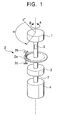
- Fig. 1 is a perspective view illustrating the basic structure of the first embodiment.
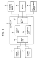
- Fig. 2 is a block diagram illustrating the electric system including a controller for the first embodiment.
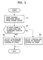
- Fig. 3 is a flow chart describing the operating process of the first embodiment for continuing the locking of a knob and for releasing the locking of the knob.
- the first embodiment of the present invention is an input device that outputs an operating signal for operating an electric apparatus such as an in-vehicle electric apparatus.
- an electric apparatus such as an in-vehicle electric apparatus.
- the airflow of an in-vehicle air conditioner may be controlled, the air outlet of the in-vehicle air conditioner may be switched, the volume and the tuning of a radio may be controlled, and the volume and the tone of audio equipment may be controlled.
- a force feedback input device for outputting an operating signal for controlling the air flow of an in-vehicle air conditioner will be described below.
- a knob 1 is manually turned, for example, by an operator, in direction A or B indicated by the arrows.
- the knob 1 is attached to a driving shaft 7.
- a rotary encoder 2 provides turning angle detecting means for detecting the turning angle of the knob 1 and for outputting a turning angle signal corresponding to the turning angle of the knob.
- the rotary encoder 2 includes a code plate 2a, which has a plurality of codes, e.g., slits, disposed along the circumference, an emitter 2b, which emits light towards the slits of the code plate 2a, and a receiver 2c, which receives the light that has passed through the slits and outputs a turning angle signal corresponding to the turning angle of the code plate 2a indicated by the light from the slits, i.e., the turning angle of the knob 1.
- a code plate 2a which has a plurality of codes, e.g., slits, disposed along the circumference
- an emitter 2b which emits light towards the slits of the code plate 2a
- a receiver 2c which receives the light that has passed through the slits and outputs a turning angle signal corresponding to the turning angle of the code plate 2a indicated by the light from the slits, i.e., the turning angle of the knob 1.
- An electromagnetic brake 3 provides locking means for preventing the knob 1 from turning and is attached around the driving shaft 7.
- a motor 4 provides turning force applying means for applying a turning force to the knob 1 and has an output shaft connected directly to the driving shaft 7 of the knob 1.
- a strain gauge 5 provides turning direction detecting means for detecting the direction the knob 1 is turned while the knob 1 is locked by the electromagnetic brake 3 and for outputting a turning direction signal corresponding to the turning direction of the knob 1. The strain gauge 5 is attached to the outer surface of the driving shaft 7.
- a controller 6 controls an air conditioner driver 8 to change the air flow of the air conditioner.
- the controller 6 includes an input unit 6a, a computing unit 6b, a memory unit 6c, and an output unit 6d.
- the input unit 6a receives a turning angle signal from the rotary encoder 2 and a turning direction signal from the strain gauge 5.
- the computing unit 6b computes the value of the operating signal from the air conditioner driver 8 corresponding to the turning angle signal sent to the input unit 6a and the motor controlling signal (voltage) for controlling the motor 4.
- the computing unit 6b also computes the value of the brake controlling signal (voltage) for controlling the electromagnetic brake 3 in response to the turning direction signal sent from the input unit 6a.
- the output unit 6d sends an operating signal, a motor controlling signal, and a brake controlling signal to the air conditioner driver 8, the motor 4, and the electromagnetic brake 3, respectively, in response to the computed results.
- the computing unit 6b determines whether the knob 1 has reached a predetermined turning angle ⁇ . If the computing unit 6b determines that the knob 1 has been turned by a turning angle ⁇ , the electromagnetic brake 3 is activated to prevent the knob 1 from turning.
- the computing unit 6b determines whether the operating force is applied in direction A to increase the turning angle of the knob. If the computing unit 6b determines that the operating force applied to the knob 1 was in direction A, the knob 1 continues to be locked by the electromagnetic brake 3. If the computing unit 6b determines that the operating force applied to the knob 1 was not in direction A, i.e., the knob 1 was turned in direction B to decrease the turning angle of the knob 1, the electromagnetic brake 3 locking the knob 1 is released.
- the memory unit 6c stores a controlling program for activating the controller 6, a first function used by the computing unit 6b for computing the value of the operating signal, a second function used by the computing unit 6b for computing the value of the motor controlling signal, and a computing equation for determining whether or not to continue locking the knob 1.
- the first function defines, for example, the value of the operating signal corresponding to the operation of the air conditioner driver 8 for increasing the air flow as the knob 1 is further turned in direction A to increase the turning angle.
- the second function defines, for example, the value of the motor controlling signal corresponding to the driving force of the motor 4 for increasing the turning force in the direction opposite to direction A.
- the first embodiment structured as described above operates as described below.
- the turning angle of the knob 1 before being turned is equal to a reference angle of 0°
- the turning angle measured from reference angle 0° of the knob 1 is detected by the rotary encoder 2.
- a turning angle signal corresponding to the turning angle of the knob 1 is sent to the input unit 6a of the controller 6.
- the computing unit 6b computes the value of the operating signal corresponding to the turning angle of the knob 1 from the turning angle of the knob 1 and the first function stored in the memory unit 6c.
- An operating signal having the value computed by the computing unit 6b is sent from the output unit 6d to the air conditioner driver 8. In this way, the air conditioner driver 8 is activated to increase the air flow of the air conditioner.
- the computing unit 6b computes the value of the operating signal, it also computes the value of the motor controlling signal corresponding to the turning angle of the knob 1 from the turning angle of the knob 1 and the second function stored in the memory unit 6c.
- the motor controlling signal having the value computed by the computing unit 6b is sent to the motor 4 from the output unit 6d.
- the motor 4 applies a turning force to the knob 1 in direction B, which is the direction opposite to the direction the knob 1 is turned, as a resistive force against the rotation of the knob 1.
- This resistive force increases as the turning angle of the knob 1 in direction A increases.
- the operator can sense how much he or she has turned the knob in direction A to increase the air flow through a sensation of resistance (force sensation) along with an increase in the resistive force.
- this turning angle ⁇ is detected by the rotary encoder 2. Then, a turning angle signal corresponding to the turning angle ⁇ is sent to the input unit 6a of the controller 6. Subsequently, the computing unit 6b makes a decision to lock the knob 1 by applying the computing equation stored in the memory unit 6c. Accordingly, a brake controlling signal is sent to the electromagnetic brake 3 from the output unit 6d to lock the knob 1. In this way, the knob 1 is prevented from being turned further than the predetermined turning angle ⁇ .
- the turning direction in which the knob 1 is turned is detected by the strain gauge 5. Then, a turning direction signal corresponding to the turning direction of the knob is sent to the input unit 6a of the controller 6 (step S1). Then, the computing unit 6b determines whether the knob 1 is turned in direction A that increases the turning angle of the knob 1 by applying the computing equation stored in the memory unit 6c (step S2).
- step S3 If the computing unit 6b determines that the knob 1 has been turned in direction A (i.e., if step S2 is YES), a brake controlling signal to continue locking the knob 1 is sent to the electromagnetic brake 3 from the output unit 6d (step S3). If the computing unit 6b determines that the knob 1 has been turned in direction B and the turning angle of the knob 1 has not been increased (i.e., if step S2 is NO), the output unit 6d sends a brake controlling signal to release the locking of the knob 1 to the electromagnetic brake 3 (step 4). In this way, the knob 1 becomes rotatable and can be turned in direction B by the turning force applied to the knob 1.
- the locking of the knob 1 can be released by applying an operating force in direction B to decrease the turning angle of the knob 1. In this way, the force feedback input device can be operated easily to release the locking of the knob 1. Consequently, the reliability of the force feedback input device is improved.
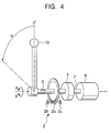
- Fig. 4 is a perspective view illustrating the basic structure of the second embodiment.
- the parts that are equivalent to those illustrated in Fig. 1 are indicated by the same reference numerals.
- the second embodiment differs from the first embodiment in that the knob is an operating lever 10.
- the structure of the second embodiment except for this operating lever 10 is the same as the structure of the first embodiment.
- the operating lever 10 according to the second embodiment operates in the same way as the knob 1 according to the first embodiment. More specifically, when the operator holds the operating lever 10 and pivots it in direction A, the pivoting angle of the operating lever 10 measured from the reference angle 0° is detected by the rotary encoder 2. Then, an operating signal with a value corresponding to the pivoting angle of the operating lever 10 is sent to the air conditioner driver 8 from the controller 6. Accordingly, the air conditioner driver 8 is activated and the air flow increases.
- a pivoting force is applied to the operating lever 10 from the motor 1 in direction B, which is the direction opposite to the direction the operating lever 10 is pivoted, to work as a resistive force against the pivoting of the operating lever 10.
- This resistive force increases as the pivoting angle of the operating lever 10 in direction A increases.
- the operator can sense how much he or she has pivoted the operating lever 10 in direction A to increase the air flow through an increase in a sensation of resistance (force sensation) provided by the operating lever 10.
- a force feedback input device including an operating lever 10 can be operated easily to release the locking of the operating lever 10. Consequently, the reliability of the force feedback input device is improved.
- the force feedback input devices provide a sensation of resistance as a force feedback.
- the present invention is not limited to this.
- the force feedback input device may provide a sensation of acceleration as a force feedback by applying a turning/pivoting force in the same direction as the knob 1/operating lever 10 is turned or may provide a sensation of clicking as a force feedback by reversing the turning/pivoting force applied to the knob 1/operating lever 10 when the turning/pivoting angle of the knob 1/operating lever 10 is greater than a predetermined angle.
- the receiver 2c of the rotary encoder 2 receives light emitted from the emitter 2b through the slits on the code plate 2a.
- the emitter 2b and the receiver 2c are formed separately.
- the rotary encoder 2 may include a code plate 2a having codes for reflecting light and an integrated emitter-receiver. In this way, the light emitted from the emitter is reflected at the codes and received by the receiver.
- the space required for installing the emitter 2b and the receiver 2c and the number of required parts can be reduced.
- the driving shaft 7 of the knob (knob 1 or operating lever 10) is directly connected to the output shaft of the motor 4.
- the present invention is not limited to this structure, and the driving shaft 7 of the knob and the output shaft of the motor 4 may be connected by a reduction gear.
- the lock is released when an operating force is applied in direction B.
- the present invention is not limited to this structure, and the locking of the knob may be released when an operating force is applied in direction A.
- an operating knob 21 is manually turned in directions A and B by an operator.
- a rotary encoder 22 is attached to a driving shaft 27 of the operating knob 21 to detect the turning angle of a driving shaft 27, i.e., the turning angle of the operating knob 21, and to send a turning angle signal corresponding to the detected turning angle.
- the rotary encoder 22 is fixed to the driving shaft 27 and includes a code plate 22a, which has a plurality of codes, e.g., slits, disposed along the circumference, and a sensor 22b, which has an emitter for emitting light to the slits of the code plate 22a and a receiver for receiving light through the slits and sending a turning angle signal corresponding to the turning angle of the code plate 22a, i.e., the turning angle of the operating knob 21.
- the sensor 22b is attached to a chassis (not depicted in the drawing) in which the operating knob 21 is journaled to.
- An electromagnetic brake 23 is disposed around the driving shaft 27 and provides turning force applying means for applying a turning force to the operating knob 21 and turning force limiting means, which also functions as locking means, for preventing the operating knob 21 from turning.
- the electromagnetic brake 23 includes an electromagnet 24 with a built-in electromagnetic coil (not depicted in the drawing) wound around an iron core and arranged in a ring and a driver 26 having an armature 25 composed of an iron plate attached by a disc-shaped leaf spring. One of the faces of the driver 26 is disposed against one of the faces of the electromagnet 24 with a gap between the two faces.
- the other face of the driver 26 is fixed to the driving shaft 27 so that the driver 26 is turnable in accordance with the operating knob 21.
- the electromagnet 24 is attached to a chassis (not depicted in the drawing) including the turning force limiting means.
- An elastic member 28 is composed of a flexible material such as flexible elastomer or hard rubber.
- the substantially columnar elastic member 28 is interposed between the operating knob 21 and the driver 26 of the electromagnetic brake 23.
- the elastic member 28 is fixed around the driving shaft 27 between the code plate 22a of the rotary encoder 22 and the driver 26 of the electromagnetic brake 23.
- a sufficient amount of bending of the elastic member 28 is equivalent to about 0.1° of the turning angle of the operating knob 21.
- the rotary encoder 22 detects the 0.1° rotation of the operating knob 21 through the elastic member 28 and sends a turning direction signal corresponding to the turning direction of the operating knob 21.
- the elastic member 28 is composed of a flexible material such as flexible elastomer or hard rubber, its structure is simple. Thus, the locking of the operating knob 21 can be released without involving a complex structure.
- a controller 29 includes an input unit 29a, a computing unit 29b, a memory unit 29c, and an output unit 29d.
- the input unit 29a receives a turning angle signal from the rotary encoder 22 and a turning direction signal.
- the computing unit 29b computes the value of the brake controlling signal (voltage) for controlling the electromagnetic brake 23 in response to the turning angle signal and the turning direction signal sent from the input unit 29a.
- the output unit 29d sends a controlling signal to the electromagnetic brake 23 in response to the computed results of the computing unit 29b.
- the computing unit 29b determines whether the operating knob 21 has been turned by a predetermined turning angle ⁇ . If the computing unit 29b determines that the operating knob 21 has been turned by a turning angle ⁇ , the electromagnetic brake 23 is activated to lock the operating knob 21.
- the computing unit 29b determines whether the operating force is applied in direction A to increase the turning angle of the operating knob 21. If the computing unit 29b determines that the operating force has been applied to the operating knob 21 in direction A, the operating knob 21 continues to be locked by the electromagnetic brake 23. If the computing unit 29b determines that the operating force has not been applied to the operating knob 21 in direction A, i.e., the operating knob 21 has been turned in direction B to decrease the turning angle of the operating knob 21, the electromagnetic brake 23 locking the operating knob 21 is released.
- the memory unit 29c stores a controlling program for activating the controller 29, a function used by the computing unit 29b for computing the value of the controlling signal, and a computing equation for determining the locking and the releasing of the operating knob 21.
- the function defines, for example, the value of the controlling signal corresponding to the driving force of the electromagnetic brake 23 for increasing the turning force applied in the direction opposite to direction A.
- the force feedback input device structured as described above operates as described below.
- the turning angle of the knob 21 before being turned is equal to a reference angle of 0°
- the turning angle measured from reference angle 0° of the operating knob 21 is detected by the rotary encoder 22.
- a turning angle signal corresponding to the turning angle of the operating knob 21 is sent to the input unit 29a of the controller 29.
- the computing unit 29b computes the value of an operating signal corresponding to the turning angle of the operating knob 21 from the turning angle of the operating knob 21 and the function stored in the memory unit 29c.
- An operating signal having the value computed by the computing unit 29b is sent from the output unit 29d. In this way, the air flow of, for example, an air conditioner is increased.
- the computing unit 29b also computes the value of the controlling signal of the electromagnetic brake 23 corresponding to the turning angle of the operating knob 21.
- the controlling signal having the value computed by the computing unit 29b is sent to the electromagnetic brake 23 from the output unit 29d.
- the electromagnetic brake 23 applies a resistive force against the turning direction of the operating knob 21. This resistive force increases as the turning angle of the operating knob 21 in direction A increases. In other words, the operator can sense how much he or she has turned the knob in direction A to increase the air flow through the increase in sensation of resistance (force sensation) provided by the operating knob 21.
- this turning angle ⁇ is detected by the rotary encoder 22. Then, a turning angle signal corresponding to the turning angle ⁇ is sent to the input unit 29a of the controller 29. Subsequently, the computing unit 29b makes a decision to lock the operating knob 21 by applying the computing equation stored in the memory unit 29c. Accordingly, a brake controlling signal is sent to the electromagnetic brake 23 from the output unit 29d to lock of the operating knob 21. In this way, the operating knob 21 is prevented from being turned further than the predetermined turning angle ⁇ .
- the turning direction of the operating force applied to the operating knob 21 is detected by the rotary encoder 22 through the bending of the elastic member 28. Then, a turning direction signal corresponding to the turning direction of the operating force is sent to the input unit 29a of the controller 29 (step S1). Then, the computing unit 29b determines whether the operating force has been applied to the operating knob 21 in direction A providing a sensation of hitting a wall in which the turning angle of the operating knob 21 is increased according to the computing equation stored in the memory unit 29c (step S2).
- step S3 a brake controlling signal for continuing the locking of the operating knob 21 is sent to the electromagnetic brake 23 from the output unit 29d (step S3), and the operating knob 21 continues to be locked.
- step S3 the computing unit 29b determines that the operating force has been applied to the operating knob 21 in direction B in which the sensation of hitting a wall is reduced and the turning angle of the operating knob 21 is not increased (i.e., if step S2 is NO)
- the output unit 29d sends a brake controlling signal for releasing the locking of the operating knob 21 to the electromagnetic brake 23 (step 4). In this way, the operating knob 21 becomes rotatable and can be turned in direction B by the operating force applied to the operating knob 21.
- the direction of the operating force applied to the operating knob 21 can be detected through the bending of the elastic member 28. Then, a turning direction signal corresponding to the turning direction of the operating knob 21 is sent to the rotary encoder 22.
- the operating knob 21 continues to be locked.
- the operating knob 21 becomes rotatable. Therefore, even when the operating knob 21 is locked and a sensation of hitting a wall is provided, the locking of the operating knob 21 can be easily released by applying a slight amount of force. Consequently, the reliability of the force feedback input device is improved.
- the electromagnet 24 and the armature 25 provide a strong adsorption force for preventing the operating knob 21 from turning.
- Fig. 8 illustrates another embodiment of the force feedback input device according to the present invention.
- two plate elastic members 31 composed of flexible elastomer or hard rubber are disposed opposingly and connect a chassis 32 and an electromagnet 24, instead of the elastic member 28 show in Fig. 5.
- An operating knob 21 and a driver 26 of the electromagnetic brake 23 are connected directly by the driving shaft 27.
- the elastic members 31 are supported by connecting plates 33 and 34 and are disposed between the electromagnet 24 and the chassis 32.
- a sensor 22b of a rotary encoder 22 is fixed to a fixing plate 35 extending from the chassis 32.
- the elastic members 31 bend.
- the sensor 22b detects the direction of the operating force applied to the operating knob 21.
- the rotary encoder 22 sends a turning direction signal corresponding to the turning direction of the operating force.
- the opposing pair of elastic members 31 are twisted as the operating knob 21 is turned.
- the rotary encoder 22 may be installed not only adjacent to the operating knob 21 but also in any position. In this way, the space required for the structure may be minimized.
- the force feedback input device provides a sensation of resistance as a force feedback.
- the present invention is not limited to this, and other force feedback input devices that provide a sensation of acceleration or a sensation of clicking as a force feedback may be used.
- the rotary encoder 22 detects the transmission of light through the slits. Instead, a code plate having codes for reflecting the light may be used.
- the electromagnetic brake 23 was used as turning force limiting means (i.e., turning force applying means and locking means).
- the present invention is not limited to this, and an electromagnetic clutch may be used instead.
- the locking is released by applying an operating force to the operating knob 21 in direction B.
- the present invention is not limited to this, and the lock may be released when an operating force is applied in direction A.
Abstract
Description
- The present invention relates to an input device for outputting an operation signal for operating an electronic apparatus such as an in-vehicle electronic apparatus. More specifically, the invention relates to a force feedback input device having a knob that provides a predetermined dynamic sensation (force sensation) to the operator by applying a turning force to the knob in accordance with the turning angle.
- A known force feedback input device comprises a knob to be rotated manually, a rotary encoder for detecting the turning angle of the knob, a motor for applying a turning force to the knob, and a controller for controlling the motor in accordance with the turning angle of the knob detected by the rotary encoder and for outputting an operating signal corresponding to the turning angle of the knob to a separate device which is controlled by the knob.
- By manually rotating a knob, the force feedback input device outputs an operating signal for operating an electric apparatus such as an in-vehicle electric apparatus. By operating the knob of the force feedback input device, for example, the airflow of an in-vehicle air conditioner may be controlled, the air outlet of the in-vehicle air conditioner may be switched, the volume and the tuning of the radio may be controlled, and the volume and the tone of the audio equipment may be controlled. Furthermore, the force feedback input device is applied in a so-called steer-by-wire system, which is installed on a steering apparatus to steer the vehicle and provide force feedback from the tires.
- To control the air flow from an in-vehicle air conditioner, the knob is set, for example, so that when it is turned in a direction that increases the air flow, a motor applies a turning force to the knob in a direction opposite to the direction the knob is turned. In this way, as the knob is turned in the direction to increase the air flow, the turning force applied in the direction opposite to the direction the knob is turned is increased. In other words, the operator can sense how much he or she has turned the knob in the direction to increase the air flow through the increase in a sensation of resistance (force sensation) provided by the knob.
- As well as the above-mentioned force feedback input device that provides a sensation of resistance as a force feedback, other force feedback input devices are known that provide a sensation of acceleration as a force feedback by applying a turning force in the direction the knob is turned or provide a sensation of clicking as a force feedback by reversing the turning force applied to the knob when the turning angle of the knob becomes greater than a predetermined turning angle, as is disclosed in Japanese Unexamined Patent Application Publication No. 2003-50639.
- In the force feedback input device described above, the knob must be prevented from being turned by more than a predetermined turning angle. In other words, when the turning angle of the knob reaches a predetermined turning angle, the knob must be locked. Once the knob is locked, however, the problem is how to release the knob. For instance, if an instructing device for instructing the locking means to release the lock is disposed separately from the force feedback input device, the operator must perform a series of complicated operations of first letting go of the knob to operate the instructing device and then operating the knob again to release the locking of the knob.
- An object of the present invention is to take into consideration the above-mentioned problem and provide a force feedback input device including locking means for stopping the rotation of the knob that is easy to operate to release the locking of the knob.
- To achieve the above-mentioned object, the present invention provides a force feedback input device comprising a turning knob, turning angle detecting means for detecting the turning angle and the turning direction of the knob and for outputting a turning angle signal corresponding to the turning angle and the turning direction of the knob, turning force applying means for applying a turning force to the knob, locking means for stopping the rotation of the knob, and a controller for driving the locking means in accordance with the turning angle signal. The force feedback input device according to the present invention further comprises turning direction detecting means for detecting the direction of the operating force applied to the knob when the rotation of the knob is locked by the locking means. The controller of the force feedback input device determines whether the operating force is applied to the knob in a predetermined direction while the knob is locked. If the controller determines that the operating force is applied in the predetermined direction, the controller drives the locking means so that the knob continues to be locked. If the controller determines that the operating force is not applied in the predetermined direction, the controller drives the locking means so that the locking of the knob is released.
- In the present invention structured as described above, when an operator turns the knob, the rotation of the knob is detected by turning angle detecting means and a turning angle signal corresponding to the turning angle of the knob is sent to the controller. Then, the controller sends a controlling signal corresponding to the turning angle of the knob to turning force applying means. In this way, the turning force applying means applies a turning force corresponding to the turning angle of the knob to the knob. In other words, in the present invention, by applying a turning force corresponding to the turning angle to the knob, the knob provides a predetermined dynamic sensation (force sensation) to the operator.
- When the knob is turned to a predetermined turning angle, the predetermined turning angle is detected by the turning angle detecting means, and a turning angle signal corresponding to the predetermined turning angle is sent to the controller. Then, a controlling signal for locking the knob is sent from the controller to the locking means, and the knob is prevented from turning further than the predetermined turning angle. When the operator tries to turn the knob while the knob is locked, the direction of the operating force applied to the knob by the operator is detected by the turning direction detecting means, and a turning direction signal corresponding to the turning direction of the applied operating force is sent to the controller. Then, it is determined whether the turning direction of the operating force is applied in a predetermined direction. If the direction of the operating force is determined to be applied in the predetermined direction, a controlling signal for continuing the locking of the knob is sent from the controller to the locking means. In this way, the knob continues to be locked. If the direction of the operating force is determined not to be applied in the predetermined direction, a controlling signal for releasing the locking of the knob is sent from the controller to the locking means. In this way, the knob becomes rotatable in a direction that reduces the turning angle of the knob. Then, the knob is turned by the operating force applied by the operator.
- According to the present invention, if an operating force is applied to the knob while the knob is locked, the locking of the knob is released. In this way, a force feedback input device that can be easily operated to release the locking of the knob may be provided.
- The turning direction detecting means of the present invention is a strain gauge.
- The knob and the turning angle detecting means of the present invention are supported by an elastic member that bends as the knob is turned while the knob is locked. The turning angle detecting means also functions as turning direction detecting means.
- The elastic member of the present invention is interposed between the turning angle detecting means attached to the knob and the locking means.
- The elastic member of the present invention is interposed between a chassis and the locking means in the chassis.
-
- Fig. 1 is a perspective view of the basic structure of a first embodiment of the present invention;
- Fig. 2 is a block diagram of the electric system including a controller of the first embodiment of the present invention;
- Fig. 3 is a flow chart describing the operating process of the first embodiment for continuing the locking of the knob and for releasing the locking of the knob;
- Fig. 4 is a perspective view of the basic structure of a second embodiment of the present invention;
- Fig. 5 is a perspective view of the structure of the force feedback input device according to a third embodiment;
- Fig. 6 is a block diagram of the electric system including a controller of the force feedback input device according to the third embodiment of the present invention;
- Fig. 7 is a flow chart describing the operating process of the operating knob according to the third embodiment of the present invention; and
- Fig. 8 is a perspective view of the structure of a force feedback input device according to a fourth embodiment of the present invention.
-
- Embodiments of a force feedback input device according to the present invention will be described below.
- A first embodiment of the present invention will be described below by referring to Figs. 1 to 3.
- Fig. 1 is a perspective view illustrating the basic structure of the first embodiment. Fig. 2 is a block diagram illustrating the electric system including a controller for the first embodiment. Fig. 3 is a flow chart describing the operating process of the first embodiment for continuing the locking of a knob and for releasing the locking of the knob.
- The first embodiment of the present invention is an input device that outputs an operating signal for operating an electric apparatus such as an in-vehicle electric apparatus. By operating the input device, the airflow of an in-vehicle air conditioner may be controlled, the air outlet of the in-vehicle air conditioner may be switched, the volume and the tuning of a radio may be controlled, and the volume and the tone of audio equipment may be controlled. In particular, a force feedback input device for outputting an operating signal for controlling the air flow of an in-vehicle air conditioner will be described below.
- As illustrated in Fig. 1, a knob 1 is manually turned, for example, by an operator, in direction A or B indicated by the arrows. The knob 1 is attached to a driving
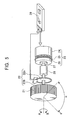
shaft 7. Arotary encoder 2 provides turning angle detecting means for detecting the turning angle of the knob 1 and for outputting a turning angle signal corresponding to the turning angle of the knob. Therotary encoder 2 includes acode plate 2a, which has a plurality of codes, e.g., slits, disposed along the circumference, anemitter 2b, which emits light towards the slits of thecode plate 2a, and areceiver 2c, which receives the light that has passed through the slits and outputs a turning angle signal corresponding to the turning angle of thecode plate 2a indicated by the light from the slits, i.e., the turning angle of the knob 1. - An
electromagnetic brake 3 provides locking means for preventing the knob 1 from turning and is attached around the drivingshaft 7. Amotor 4 provides turning force applying means for applying a turning force to the knob 1 and has an output shaft connected directly to the drivingshaft 7 of the knob 1. Astrain gauge 5 provides turning direction detecting means for detecting the direction the knob 1 is turned while the knob 1 is locked by theelectromagnetic brake 3 and for outputting a turning direction signal corresponding to the turning direction of the knob 1. Thestrain gauge 5 is attached to the outer surface of the drivingshaft 7. - As illustrated in Fig. 2, a
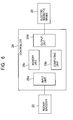
controller 6 controls anair conditioner driver 8 to change the air flow of the air conditioner. - The
controller 6 includes aninput unit 6a, acomputing unit 6b, amemory unit 6c, and anoutput unit 6d. - The
input unit 6a receives a turning angle signal from therotary encoder 2 and a turning direction signal from thestrain gauge 5. Thecomputing unit 6b computes the value of the operating signal from theair conditioner driver 8 corresponding to the turning angle signal sent to theinput unit 6a and the motor controlling signal (voltage) for controlling themotor 4. Thecomputing unit 6b also computes the value of the brake controlling signal (voltage) for controlling theelectromagnetic brake 3 in response to the turning direction signal sent from theinput unit 6a. Theoutput unit 6d sends an operating signal, a motor controlling signal, and a brake controlling signal to theair conditioner driver 8, themotor 4, and theelectromagnetic brake 3, respectively, in response to the computed results. - The
computing unit 6b determines whether the knob 1 has reached a predetermined turning angle α. If thecomputing unit 6b determines that the knob 1 has been turned by a turning angle α, theelectromagnetic brake 3 is activated to prevent the knob 1 from turning. - If an operating force is applied to the knob 1 after the
computing unit 6b determines that the knob 1 has been turned by the turning angle α, thecomputing unit 6b determines whether the operating force is applied in direction A to increase the turning angle of the knob. If thecomputing unit 6b determines that the operating force applied to the knob 1 was in direction A, the knob 1 continues to be locked by theelectromagnetic brake 3. If thecomputing unit 6b determines that the operating force applied to the knob 1 was not in direction A, i.e., the knob 1 was turned in direction B to decrease the turning angle of the knob 1, theelectromagnetic brake 3 locking the knob 1 is released. - The
memory unit 6c stores a controlling program for activating thecontroller 6, a first function used by thecomputing unit 6b for computing the value of the operating signal, a second function used by thecomputing unit 6b for computing the value of the motor controlling signal, and a computing equation for determining whether or not to continue locking the knob 1. - The first function defines, for example, the value of the operating signal corresponding to the operation of the
air conditioner driver 8 for increasing the air flow as the knob 1 is further turned in direction A to increase the turning angle. The second function defines, for example, the value of the motor controlling signal corresponding to the driving force of themotor 4 for increasing the turning force in the direction opposite to direction A. - The first embodiment structured as described above operates as described below.
- Assuming that the turning angle of the knob 1 before being turned is equal to a reference angle of 0°, when the operator turns the knob 1 from reference angle 0° in direction A, the turning angle measured from reference angle 0° of the knob 1 is detected by the
rotary encoder 2. Then, a turning angle signal corresponding to the turning angle of the knob 1 is sent to theinput unit 6a of thecontroller 6. Subsequently, thecomputing unit 6b computes the value of the operating signal corresponding to the turning angle of the knob 1 from the turning angle of the knob 1 and the first function stored in thememory unit 6c. An operating signal having the value computed by thecomputing unit 6b is sent from theoutput unit 6d to theair conditioner driver 8. In this way, theair conditioner driver 8 is activated to increase the air flow of the air conditioner. - At the same time the
computing unit 6b computes the value of the operating signal, it also computes the value of the motor controlling signal corresponding to the turning angle of the knob 1 from the turning angle of the knob 1 and the second function stored in thememory unit 6c. The motor controlling signal having the value computed by thecomputing unit 6b is sent to themotor 4 from theoutput unit 6d. In this way, themotor 4 applies a turning force to the knob 1 in direction B, which is the direction opposite to the direction the knob 1 is turned, as a resistive force against the rotation of the knob 1. This resistive force increases as the turning angle of the knob 1 in direction A increases. In other words, the operator can sense how much he or she has turned the knob in direction A to increase the air flow through a sensation of resistance (force sensation) along with an increase in the resistive force. - When the knob 1 is turned by a predetermined turning angle α, this turning angle α is detected by the
rotary encoder 2. Then, a turning angle signal corresponding to the turning angle α is sent to theinput unit 6a of thecontroller 6. Subsequently, thecomputing unit 6b makes a decision to lock the knob 1 by applying the computing equation stored in thememory unit 6c. Accordingly, a brake controlling signal is sent to theelectromagnetic brake 3 from theoutput unit 6d to lock the knob 1. In this way, the knob 1 is prevented from being turned further than the predetermined turning angle α. - If the operator tries to turn the knob 1 by applying an operating force to the knob 1 while the knob 1 is locked as described above, the steps described in Fig. 3 are carried out.
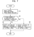
- More specifically, the turning direction in which the knob 1 is turned is detected by the
strain gauge 5. Then, a turning direction signal corresponding to the turning direction of the knob is sent to theinput unit 6a of the controller 6 (step S1). Then, thecomputing unit 6b determines whether the knob 1 is turned in direction A that increases the turning angle of the knob 1 by applying the computing equation stored in thememory unit 6c (step S2). - If the
computing unit 6b determines that the knob 1 has been turned in direction A (i.e., if step S2 is YES), a brake controlling signal to continue locking the knob 1 is sent to theelectromagnetic brake 3 from theoutput unit 6d (step S3). If thecomputing unit 6b determines that the knob 1 has been turned in direction B and the turning angle of the knob 1 has not been increased (i.e., if step S2 is NO), theoutput unit 6d sends a brake controlling signal to release the locking of the knob 1 to the electromagnetic brake 3 (step 4). In this way, the knob 1 becomes rotatable and can be turned in direction B by the turning force applied to the knob 1. - According to the first embodiment, the following advantages are achieved.
- When the knob 1 is locked and cannot be turned, the locking of the knob 1 can be released by applying an operating force in direction B to decrease the turning angle of the knob 1. In this way, the force feedback input device can be operated easily to release the locking of the knob 1. Consequently, the reliability of the force feedback input device is improved.
- A second embodiment of the present invention will be described below by referring to Fig. 4.
- Fig. 4 is a perspective view illustrating the basic structure of the second embodiment. In Fig. 4, the parts that are equivalent to those illustrated in Fig. 1 are indicated by the same reference numerals.
- The second embodiment differs from the first embodiment in that the knob is an operating
lever 10. The structure of the second embodiment except for this operatinglever 10 is the same as the structure of the first embodiment. - The operating
lever 10 according to the second embodiment operates in the same way as the knob 1 according to the first embodiment. More specifically, when the operator holds the operatinglever 10 and pivots it in direction A, the pivoting angle of the operatinglever 10 measured from the reference angle 0° is detected by therotary encoder 2. Then, an operating signal with a value corresponding to the pivoting angle of the operatinglever 10 is sent to theair conditioner driver 8 from thecontroller 6. Accordingly, theair conditioner driver 8 is activated and the air flow increases. - While the
controller 6 outputs the operating signal, it also outputs a motor controlling signal. According to the motor controlling signal, a pivoting force is applied to the operatinglever 10 from the motor 1 in direction B, which is the direction opposite to the direction the operatinglever 10 is pivoted, to work as a resistive force against the pivoting of the operatinglever 10. This resistive force increases as the pivoting angle of the operatinglever 10 in direction A increases. In other words, the operator can sense how much he or she has pivoted the operatinglever 10 in direction A to increase the air flow through an increase in a sensation of resistance (force sensation) provided by the operatinglever 10. - When the pivoting angle of the operating
lever 10 reaches a predetermined angle α, the operatinglever 10 is locked by theelectromagnetic brake 3. - By applying an operating force to the operating
lever 10 in direction B while the operatinglever 10 is locked, the locking of the operatinglever 10 is released, allowing the operatinglever 10 to be pivoted in direction B. - According to the second embodiment, a force feedback input device including an operating
lever 10 can be operated easily to release the locking of the operatinglever 10. Consequently, the reliability of the force feedback input device is improved. - In the first and second embodiments, the force feedback input devices provide a sensation of resistance as a force feedback. The present invention, however, is not limited to this. The force feedback input device may provide a sensation of acceleration as a force feedback by applying a turning/pivoting force in the same direction as the knob 1/
operating lever 10 is turned or may provide a sensation of clicking as a force feedback by reversing the turning/pivoting force applied to the knob 1/operating lever 10 when the turning/pivoting angle of the knob 1/operating lever 10 is greater than a predetermined angle. - In the first and second embodiments, the
receiver 2c of therotary encoder 2 receives light emitted from theemitter 2b through the slits on thecode plate 2a. In this case, theemitter 2b and thereceiver 2c are formed separately. The present invention, however, is not limited to this structure. In other words, therotary encoder 2 may include acode plate 2a having codes for reflecting light and an integrated emitter-receiver. In this way, the light emitted from the emitter is reflected at the codes and received by the receiver. For such arotary encoder 2, the space required for installing theemitter 2b and thereceiver 2c and the number of required parts can be reduced. - In the first and second embodiments, as illustrated in Fig. 1, the driving
shaft 7 of the knob (knob 1 or operating lever 10) is directly connected to the output shaft of themotor 4. The present invention, however, is not limited to this structure, and the drivingshaft 7 of the knob and the output shaft of themotor 4 may be connected by a reduction gear. - In the first and second embodiments, if the knob (knob 1 or operating lever 10) is locked, the lock is released when an operating force is applied in direction B. The present invention, however, is not limited to this structure, and the locking of the knob may be released when an operating force is applied in direction A.
- The third embodiment of the present invention will be described below by referring to Figs. 5 to 7.
- In Fig. 5, an operating
knob 21 is manually turned in directions A and B by an operator. Arotary encoder 22 is attached to a drivingshaft 27 of the operatingknob 21 to detect the turning angle of a drivingshaft 27, i.e., the turning angle of the operatingknob 21, and to send a turning angle signal corresponding to the detected turning angle. Therotary encoder 22 is fixed to the drivingshaft 27 and includes acode plate 22a, which has a plurality of codes, e.g., slits, disposed along the circumference, and asensor 22b, which has an emitter for emitting light to the slits of thecode plate 22a and a receiver for receiving light through the slits and sending a turning angle signal corresponding to the turning angle of thecode plate 22a, i.e., the turning angle of the operatingknob 21. Thesensor 22b is attached to a chassis (not depicted in the drawing) in which the operatingknob 21 is journaled to. - An
electromagnetic brake 23 is disposed around the drivingshaft 27 and provides turning force applying means for applying a turning force to the operatingknob 21 and turning force limiting means, which also functions as locking means, for preventing the operatingknob 21 from turning. Theelectromagnetic brake 23 includes anelectromagnet 24 with a built-in electromagnetic coil (not depicted in the drawing) wound around an iron core and arranged in a ring and adriver 26 having anarmature 25 composed of an iron plate attached by a disc-shaped leaf spring. One of the faces of thedriver 26 is disposed against one of the faces of theelectromagnet 24 with a gap between the two faces. - The other face of the
driver 26 is fixed to the drivingshaft 27 so that thedriver 26 is turnable in accordance with the operatingknob 21. Theelectromagnet 24 is attached to a chassis (not depicted in the drawing) including the turning force limiting means. - An
elastic member 28 is composed of a flexible material such as flexible elastomer or hard rubber. The substantially columnarelastic member 28 is interposed between the operatingknob 21 and thedriver 26 of theelectromagnetic brake 23. Theelastic member 28 is fixed around the drivingshaft 27 between thecode plate 22a of therotary encoder 22 and thedriver 26 of theelectromagnetic brake 23. - When the operating
knob 21 is turned while the operatingknob 21 is locked by theelectromagnetic brake 23, the turning direction of the operating force applied to the operatingknob 21 is detected by the bending of theelastic member 28. Then, a turning direction signal corresponding to the turning direction of the operatingknob 21 is sent from therotary encoder 22. - A sufficient amount of bending of the
elastic member 28 is equivalent to about 0.1° of the turning angle of the operatingknob 21. Therotary encoder 22 detects the 0.1° rotation of the operatingknob 21 through theelastic member 28 and sends a turning direction signal corresponding to the turning direction of the operatingknob 21. - Since the
elastic member 28 is composed of a flexible material such as flexible elastomer or hard rubber, its structure is simple. Thus, the locking of the operatingknob 21 can be released without involving a complex structure. - A
controller 29 includes aninput unit 29a, acomputing unit 29b, amemory unit 29c, and anoutput unit 29d. Theinput unit 29a receives a turning angle signal from therotary encoder 22 and a turning direction signal. Thecomputing unit 29b computes the value of the brake controlling signal (voltage) for controlling theelectromagnetic brake 23 in response to the turning angle signal and the turning direction signal sent from theinput unit 29a. Theoutput unit 29d sends a controlling signal to theelectromagnetic brake 23 in response to the computed results of thecomputing unit 29b. - The
computing unit 29b determines whether the operatingknob 21 has been turned by a predetermined turning angle α. If thecomputing unit 29b determines that the operatingknob 21 has been turned by a turning angle α, theelectromagnetic brake 23 is activated to lock the operatingknob 21. - If an operating force is applied to the operating
knob 21 after thecomputing unit 29b determines that the operatingknob 21 has been turned by a turning angle α, thecomputing unit 29b determines whether the operating force is applied in direction A to increase the turning angle of the operatingknob 21. If thecomputing unit 29b determines that the operating force has been applied to the operatingknob 21 in direction A, the operatingknob 21 continues to be locked by theelectromagnetic brake 23. If thecomputing unit 29b determines that the operating force has not been applied to the operatingknob 21 in direction A, i.e., the operatingknob 21 has been turned in direction B to decrease the turning angle of the operatingknob 21, theelectromagnetic brake 23 locking the operatingknob 21 is released. - The
memory unit 29c stores a controlling program for activating thecontroller 29, a function used by thecomputing unit 29b for computing the value of the controlling signal, and a computing equation for determining the locking and the releasing of the operatingknob 21. - The function defines, for example, the value of the controlling signal corresponding to the driving force of the
electromagnetic brake 23 for increasing the turning force applied in the direction opposite to direction A. - The force feedback input device structured as described above operates as described below.
- Assuming that the turning angle of the
knob 21 before being turned is equal to a reference angle of 0°, when the operator turns the operatingknob 21 from reference angle 0° in direction A, the turning angle measured from reference angle 0° of the operatingknob 21 is detected by therotary encoder 22. Then, a turning angle signal corresponding to the turning angle of the operatingknob 21 is sent to theinput unit 29a of thecontroller 29. Subsequently, thecomputing unit 29b computes the value of an operating signal corresponding to the turning angle of the operatingknob 21 from the turning angle of the operatingknob 21 and the function stored in thememory unit 29c. An operating signal having the value computed by thecomputing unit 29b is sent from theoutput unit 29d. In this way, the air flow of, for example, an air conditioner is increased. - At the same time, the
computing unit 29b also computes the value of the controlling signal of theelectromagnetic brake 23 corresponding to the turning angle of the operatingknob 21. The controlling signal having the value computed by thecomputing unit 29b is sent to theelectromagnetic brake 23 from theoutput unit 29d. In this way, theelectromagnetic brake 23 applies a resistive force against the turning direction of the operatingknob 21. This resistive force increases as the turning angle of the operatingknob 21 in direction A increases. In other words, the operator can sense how much he or she has turned the knob in direction A to increase the air flow through the increase in sensation of resistance (force sensation) provided by the operatingknob 21. - When the operating
knob 21 is turned by a predetermined turning angle α, this turning angle α is detected by therotary encoder 22. Then, a turning angle signal corresponding to the turning angle α is sent to theinput unit 29a of thecontroller 29. Subsequently, thecomputing unit 29b makes a decision to lock the operatingknob 21 by applying the computing equation stored in thememory unit 29c. Accordingly, a brake controlling signal is sent to theelectromagnetic brake 23 from theoutput unit 29d to lock of the operatingknob 21. In this way, the operatingknob 21 is prevented from being turned further than the predetermined turning angle α. - If the operator tries to turn the operating
knob 21 by applying an operating force to the operatingknob 21 while the operatingknob 21 is locked as described above, the steps described in Fig. 7 are carried out. - More specifically, when the operating
knob 21 is locked (i.e., when there is a sensation of hitting a wall), the turning direction of the operating force applied to the operatingknob 21 is detected by therotary encoder 22 through the bending of theelastic member 28. Then, a turning direction signal corresponding to the turning direction of the operating force is sent to theinput unit 29a of the controller 29 (step S1). Then, thecomputing unit 29b determines whether the operating force has been applied to the operatingknob 21 in direction A providing a sensation of hitting a wall in which the turning angle of the operatingknob 21 is increased according to the computing equation stored in thememory unit 29c (step S2). - If the
computing unit 29b determines that the operating force has been applied to the operatingknob 21 in direction A providing a sensation of hitting a wall (i.e., if step S2 is YES), a brake controlling signal for continuing the locking of the operatingknob 21 is sent to theelectromagnetic brake 23 from theoutput unit 29d (step S3), and the operatingknob 21 continues to be locked. If thecomputing unit 29b determines that the operating force has been applied to the operatingknob 21 in direction B in which the sensation of hitting a wall is reduced and the turning angle of the operatingknob 21 is not increased (i.e., if step S2 is NO), theoutput unit 29d sends a brake controlling signal for releasing the locking of the operatingknob 21 to the electromagnetic brake 23 (step 4). In this way, the operatingknob 21 becomes rotatable and can be turned in direction B by the operating force applied to the operatingknob 21. - According to the above-mentioned embodiment of the present invention, when the operating
knob 21 is locked by theelectromagnetic brake 23 and a sensation of hitting a wall is provided, the direction of the operating force applied to the operatingknob 21 can be detected through the bending of theelastic member 28. Then, a turning direction signal corresponding to the turning direction of the operatingknob 21 is sent to therotary encoder 22. In this way, when an operating force is applied to the operatingknob 21 in the direction increasing the turning angle, the operatingknob 21 continues to be locked. When an operating force is applied to the operatingknob 21 in the direction decreasing the turning angle, the operatingknob 21 becomes rotatable. Therefore, even when the operatingknob 21 is locked and a sensation of hitting a wall is provided, the locking of the operatingknob 21 can be easily released by applying a slight amount of force. Consequently, the reliability of the force feedback input device is improved. - Since the
elastic member 28 is interposed between the operatingknob 21 and theelectromagnetic brake 23, the structure becomes simple and the locking of the operatingknob 21 can be sufficiently released. - By using the
electromagnetic brake 23 as turning force limiting means, theelectromagnet 24 and thearmature 25 provide a strong adsorption force for preventing the operatingknob 21 from turning. - Fig. 8 illustrates another embodiment of the force feedback input device according to the present invention.
- In Fig. 8, the parts that are equivalent to those illustrated in Fig. 5 are indicated by the same reference numerals and their descriptions are omitted.
- In this embodiment, two plate
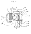
elastic members 31 composed of flexible elastomer or hard rubber are disposed opposingly and connect achassis 32 and anelectromagnet 24, instead of theelastic member 28 show in Fig. 5. An operatingknob 21 and adriver 26 of theelectromagnetic brake 23 are connected directly by the drivingshaft 27. - In this embodiment, the
elastic members 31 are supported by connectingplates electromagnet 24 and thechassis 32. Asensor 22b of arotary encoder 22 is fixed to a fixingplate 35 extending from thechassis 32. - In this embodiment, when the operating
knob 21 is turned while the operatingknob 21 is locked by theelectromagnetic brake 23, theelastic members 31 bend. As a result, thesensor 22b detects the direction of the operating force applied to the operatingknob 21. Then, therotary encoder 22 sends a turning direction signal corresponding to the turning direction of the operating force. The opposing pair ofelastic members 31 are twisted as the operatingknob 21 is turned. - According to the structure of this embodiment, since the
elastic members 31 are interposed between theelectromagnetic brake 23 and thechassis 32 with theelectromagnet 24 attached, therotary encoder 22 may be installed not only adjacent to the operatingknob 21 but also in any position. In this way, the space required for the structure may be minimized. - In the above-mentioned embodiment of the present invention, the force feedback input device provides a sensation of resistance as a force feedback. The present invention, however, is not limited to this, and other force feedback input devices that provide a sensation of acceleration or a sensation of clicking as a force feedback may be used.
- The
rotary encoder 22 according to the above-mentioned embodiment detects the transmission of light through the slits. Instead, a code plate having codes for reflecting the light may be used. - The
electromagnetic brake 23 was used as turning force limiting means (i.e., turning force applying means and locking means). The present invention, however, is not limited to this, and an electromagnetic clutch may be used instead. - When the operating
knob 21 is locked, the locking is released by applying an operating force to the operatingknob 21 in direction B. The present invention, however, is not limited to this, and the lock may be released when an operating force is applied in direction A.
Claims (5)
- A force feedback input device comprising:wherein the force feedback input device further includes turning direction detecting means for detecting the direction of the operating force applied to the knob when the rotation of the knob is locked by the locking means;a knob to be operated by turning;turning angle detecting means for detecting the turning angle and the turning direction of the knob and for outputting a turning angle signal corresponding to the turning angle and the turning direction of the knob;turning force applying means for applying a turning force to the knob;locking means for stopping the rotation of the knob; anda controller for driving the locking means in accordance with the turning angle signal;
wherein the controller of the force feedback input device determines whether the operating force is applied to the knob in a predetermined direction while the knob is locked, the controller drives the locking means to continue locking the knob if the controller determines that the operating force is applied in the predetermined direction, and the controller drives the locking means to release the locking of the knob if the controller determines that the operating force is not applied in the predetermined direction. - The force feedback input device according to claim 1, wherein the turning direction detecting means is a strain gauge.
- The force feedback input device according to claim 1 or 2, wherein an elastic member that bends when the knob is turned is interposed between the knob and the turning angle detecting means and the turning angle detecting means also functions as the turning direction detecting means.
- The force feedback input device according to claim 3, wherein the elastic member is interposed between the turning angle detecting means and the locking means.
- The force feedback input device according to claim 3, wherein the elastic member is disposed to connect the locking means and a chassis in which the locking means is attached.
Applications Claiming Priority (4)
| Application Number | Priority Date | Filing Date | Title |
|---|---|---|---|
| JP2003140567 | 2003-05-19 | ||
| JP2003140567A JP2004342019A (en) | 2003-05-19 | 2003-05-19 | Inner force sense applying type input device |
| JP2003180365 | 2003-06-25 | ||
| JP2003180365A JP2005019113A (en) | 2003-06-25 | 2003-06-25 | Tactile force applying type input device |
Publications (2)
| Publication Number | Publication Date |
|---|---|
| EP1480238A2 true EP1480238A2 (en) | 2004-11-24 |
| EP1480238A3 EP1480238A3 (en) | 2006-05-17 |
Family
ID=33100431
Family Applications (1)
| Application Number | Title | Priority Date | Filing Date |
|---|---|---|---|
| EP04011774A Withdrawn EP1480238A3 (en) | 2003-05-19 | 2004-05-18 | Force feedback input device |
Country Status (3)
| Country | Link |
|---|---|
| US (1) | US7124648B2 (en) |
| EP (1) | EP1480238A3 (en) |
| CN (1) | CN1551041A (en) |
Cited By (9)
| Publication number | Priority date | Publication date | Assignee | Title |
|---|---|---|---|---|
| DE102005017993A1 (en) * | 2005-04-19 | 2006-10-26 | Bayerische Motoren Werke Ag | Control unit, for use in flow blade of motor vehicle air outlet, has electrically controlled piezo-brake operating on rotating wheel, through which rotating wheel can be released, broken or blocked |
| WO2007003394A1 (en) * | 2005-07-01 | 2007-01-11 | Preh Gmbh | Rotary actuator comprising a magnetic braking mechanism |
| EP1865525A1 (en) * | 2006-06-09 | 2007-12-12 | Kabushiki Kaisha Tokai-Rika-Denki-Seisakusho | Switch device |
| EP1908685A2 (en) | 2006-10-02 | 2008-04-09 | Honeywell International Inc. | Motor balanced active user interface assembly |
| EP2594423A1 (en) * | 2011-11-21 | 2013-05-22 | Valeo Autoklimatizace k.s. | Control device |
| US20150234418A1 (en) * | 2012-09-14 | 2015-08-20 | Audi Ag | Control device for a functional device of a motor vehicle |
| CN104908046A (en) * | 2015-06-16 | 2015-09-16 | 东南大学 | Hand controller based on rotary knob type force feedback and mechanical arm remote operating control method |
| EP3514657A4 (en) * | 2016-09-16 | 2020-06-17 | Alps Alpine Co., Ltd. | Operation feel imparting type input device |
| DE112016003865B4 (en) | 2015-08-24 | 2023-10-12 | Panasonic Intellectual Property Management Co., Ltd. | Input device |
Families Citing this family (20)
| Publication number | Priority date | Publication date | Assignee | Title |
|---|---|---|---|---|
| JP3934394B2 (en) * | 2001-10-30 | 2007-06-20 | アルプス電気株式会社 | Haptic input device |
| JP4180455B2 (en) * | 2003-07-24 | 2008-11-12 | アルプス電気株式会社 | Haptic input device |
| JP4439524B2 (en) * | 2003-11-20 | 2010-03-24 | プレー・ゲゼルシャフト・ミト・ベシュレンクテル・ハフツング | Operation parts |
| JP2007538301A (en) * | 2004-01-29 | 2007-12-27 | プレー・ゲゼルシャフト・ミト・ベシュレンクテル・ハフツング | Programmable rotational torque supply device using spring parts |
| CN102866724B (en) * | 2011-07-08 | 2015-04-22 | 阿尔派株式会社 | Electronic equipment and adjustment method thereof |
| JP5792089B2 (en) * | 2012-02-08 | 2015-10-07 | アルプス電気株式会社 | Electromagnetic brake device and haptic rotation input device using the same |
| US8752439B2 (en) * | 2012-07-24 | 2014-06-17 | JEFFREY Alan HYTE | Dynamic torque sensing system |
| CN103017959A (en) * | 2012-11-23 | 2013-04-03 | 大连滨城活塞制造有限公司 | Torque rotating angle measurement device |
| US20160017983A1 (en) * | 2014-07-18 | 2016-01-21 | Dura Operating Llc | Rotary gear shifter |
| EP3512669B1 (en) * | 2016-09-14 | 2023-07-26 | KEBA Industrial Automation GmbH | Control device and control method for industrial machines having controlled movement drives |
| US10578463B2 (en) * | 2016-12-19 | 2020-03-03 | Microchip Technology Incorporated | Detection of defects in motor position decoder system |
| JP6634166B2 (en) * | 2016-12-21 | 2020-01-22 | アルプスアルパイン株式会社 | Operation device |
| CN110192259B (en) * | 2017-01-20 | 2021-05-28 | 阿尔卑斯阿尔派株式会社 | Rotary operating device and control method thereof |
| JP6793314B2 (en) * | 2017-02-21 | 2020-12-02 | パナソニックIpマネジメント株式会社 | Input device |
| US10330195B2 (en) * | 2017-06-27 | 2019-06-25 | Panasonic Corporation | Input device |
| US10395863B2 (en) | 2017-11-28 | 2019-08-27 | Denso International America, Inc. | Magnetic rotary dial |
| WO2021000149A1 (en) * | 2019-06-30 | 2021-01-07 | 瑞声声学科技(深圳)有限公司 | Vehicle-mounted rotary knob |
| WO2021000150A1 (en) * | 2019-06-30 | 2021-01-07 | 瑞声声学科技(深圳)有限公司 | Vehicle-mounted rotary knob |
| WO2021000151A1 (en) * | 2019-06-30 | 2021-01-07 | 瑞声声学科技(深圳)有限公司 | Vehicle-mounted rotary knob |
| CN112023219A (en) * | 2020-09-09 | 2020-12-04 | 林常森 | Painless automatic anesthesia device |
Citations (4)
| Publication number | Priority date | Publication date | Assignee | Title |
|---|---|---|---|---|
| WO1996006392A1 (en) * | 1994-08-18 | 1996-02-29 | Interval Research Corporation | Content-based haptic input device for video |
| US6437771B1 (en) * | 1995-01-18 | 2002-08-20 | Immersion Corporation | Force feedback device including flexure member between actuator and user object |
| WO2002088864A1 (en) * | 2001-04-26 | 2002-11-07 | Leopold Kostal Gmbh & Co. Kg | Rotating actuator |
| JP2003050639A (en) * | 2001-08-07 | 2003-02-21 | Alps Electric Co Ltd | Manual input device |
Family Cites Families (8)
| Publication number | Priority date | Publication date | Assignee | Title |
|---|---|---|---|---|
| US6686911B1 (en) * | 1996-11-26 | 2004-02-03 | Immersion Corporation | Control knob with control modes and force feedback |
| JPH117865A (en) * | 1997-04-21 | 1999-01-12 | Matsushita Electric Ind Co Ltd | Rotary operation electronic part with push switch |
| JPH1139998A (en) * | 1997-07-16 | 1999-02-12 | Matsushita Electric Ind Co Ltd | Rotary encoder |
| JP3466458B2 (en) * | 1998-02-19 | 2003-11-10 | アルプス電気株式会社 | Rotating electrical parts |
| JP3766207B2 (en) * | 1998-05-25 | 2006-04-12 | アルプス電気株式会社 | Composite operation type electric parts |
| JP4055281B2 (en) * | 1999-02-10 | 2008-03-05 | 松下電器産業株式会社 | Press / rotate electronic components |
| JP3952642B2 (en) * | 1999-09-20 | 2007-08-01 | 松下電器産業株式会社 | Press / rotate electronic components |
| US6809275B1 (en) * | 2002-05-13 | 2004-10-26 | Synaptics, Inc. | Rotary and push type input device |
-
2004
- 2004-05-11 US US10/842,901 patent/US7124648B2/en not_active Expired - Fee Related
- 2004-05-18 EP EP04011774A patent/EP1480238A3/en not_active Withdrawn
- 2004-05-19 CN CNA2004100446610A patent/CN1551041A/en active Pending
Patent Citations (4)
| Publication number | Priority date | Publication date | Assignee | Title |
|---|---|---|---|---|
| WO1996006392A1 (en) * | 1994-08-18 | 1996-02-29 | Interval Research Corporation | Content-based haptic input device for video |
| US6437771B1 (en) * | 1995-01-18 | 2002-08-20 | Immersion Corporation | Force feedback device including flexure member between actuator and user object |
| WO2002088864A1 (en) * | 2001-04-26 | 2002-11-07 | Leopold Kostal Gmbh & Co. Kg | Rotating actuator |
| JP2003050639A (en) * | 2001-08-07 | 2003-02-21 | Alps Electric Co Ltd | Manual input device |
Non-Patent Citations (1)
| Title |
|---|
| PATENT ABSTRACTS OF JAPAN vol. 2003, no. 06, 3 June 2003 (2003-06-03) & JP 2003 050639 A (ALPS ELECTRIC CO LTD), 21 February 2003 (2003-02-21) * |
Cited By (12)
| Publication number | Priority date | Publication date | Assignee | Title |
|---|---|---|---|---|
| DE102005017993A1 (en) * | 2005-04-19 | 2006-10-26 | Bayerische Motoren Werke Ag | Control unit, for use in flow blade of motor vehicle air outlet, has electrically controlled piezo-brake operating on rotating wheel, through which rotating wheel can be released, broken or blocked |
| WO2007003394A1 (en) * | 2005-07-01 | 2007-01-11 | Preh Gmbh | Rotary actuator comprising a magnetic braking mechanism |
| US7928334B2 (en) | 2005-07-01 | 2011-04-19 | Preh Gmbh | Rotary actuator with magnetic brake |
| EP1865525A1 (en) * | 2006-06-09 | 2007-12-12 | Kabushiki Kaisha Tokai-Rika-Denki-Seisakusho | Switch device |
| US7714242B2 (en) | 2006-06-09 | 2010-05-11 | Kabushiki Kaisha Tokai Rika Denki Seisakusho | Switch device |
| EP1908685A2 (en) | 2006-10-02 | 2008-04-09 | Honeywell International Inc. | Motor balanced active user interface assembly |
| EP1908685A3 (en) * | 2006-10-02 | 2012-12-12 | Honeywell International Inc. | Motor balanced active user interface assembly |
| EP2594423A1 (en) * | 2011-11-21 | 2013-05-22 | Valeo Autoklimatizace k.s. | Control device |
| US20150234418A1 (en) * | 2012-09-14 | 2015-08-20 | Audi Ag | Control device for a functional device of a motor vehicle |
| CN104908046A (en) * | 2015-06-16 | 2015-09-16 | 东南大学 | Hand controller based on rotary knob type force feedback and mechanical arm remote operating control method |
| DE112016003865B4 (en) | 2015-08-24 | 2023-10-12 | Panasonic Intellectual Property Management Co., Ltd. | Input device |
| EP3514657A4 (en) * | 2016-09-16 | 2020-06-17 | Alps Alpine Co., Ltd. | Operation feel imparting type input device |
Also Published As
| Publication number | Publication date |
|---|---|
| US7124648B2 (en) | 2006-10-24 |
| US20040231434A1 (en) | 2004-11-25 |
| EP1480238A3 (en) | 2006-05-17 |
| CN1551041A (en) | 2004-12-01 |
Similar Documents
| Publication | Publication Date | Title |
|---|---|---|
| US7124648B2 (en) | Force feedback input device | |
| US20050275205A1 (en) | Small diameter steering wheel apparatus | |
| JP6793314B2 (en) | Input device | |
| JP2005019113A (en) | Tactile force applying type input device | |
| US7027895B2 (en) | Force feedback input device | |
| US7214929B2 (en) | Force-feedback input device | |
| JP2006264384A (en) | Electric parking brake system | |
| US10935126B2 (en) | Shift device | |
| CN111098913A (en) | Steering angle limiting device for steer-by-wire system | |
| US7249650B2 (en) | Vehicle steering device | |
| CN110733561A (en) | Steer-by-wire apparatus | |
| CN109415086B (en) | Wire control steering system with different damping when entering and exiting bend | |
| CN111712774B (en) | Input device | |
| KR101726688B1 (en) | Emergency steering system and controlling method of the same | |
| US10901451B2 (en) | Input device | |
| US6805021B2 (en) | Bywire system shift lever device for vehicles | |
| US7086292B2 (en) | Force-feedback input device | |
| CN112572596B (en) | Steering system and automobile | |
| JP2003028293A (en) | Gear shift control device for vehicle | |
| JP4701699B2 (en) | Vehicle steering system | |
| EP2110731B1 (en) | Multi-directionnal input apparatus | |
| JP4430988B2 (en) | Haptic input device | |
| JP2004342019A (en) | Inner force sense applying type input device | |
| US6859003B2 (en) | Force sense imparting/inputting apparatus capable of preventing oscillation of operation member, and imparting force sense | |
| US20190211923A1 (en) | Shift device |
Legal Events
| Date | Code | Title | Description |
|---|---|---|---|
| PUAI | Public reference made under article 153(3) epc to a published international application that has entered the european phase |
Free format text: ORIGINAL CODE: 0009012 |
|
| AK | Designated contracting states |
Kind code of ref document: A2 Designated state(s): AT BE BG CH CY CZ DE DK EE ES FI FR GB GR HU IE IT LI LU MC NL PL PT RO SE SI SK TR |
|
| AX | Request for extension of the european patent |
Extension state: AL HR LT LV MK |
|
| PUAL | Search report despatched |
Free format text: ORIGINAL CODE: 0009013 |
|
| AK | Designated contracting states |
Kind code of ref document: A3 Designated state(s): AT BE BG CH CY CZ DE DK EE ES FI FR GB GR HU IE IT LI LU MC NL PL PT RO SE SI SK TR |
|
| AX | Request for extension of the european patent |
Extension state: AL HR LT LV MK |
|
| 17P | Request for examination filed |
Effective date: 20060427 |
|
| AKX | Designation fees paid |
Designated state(s): DE FR GB |
|
| STAA | Information on the status of an ep patent application or granted ep patent |
Free format text: STATUS: THE APPLICATION HAS BEEN WITHDRAWN |
|
| 18W | Application withdrawn |
Effective date: 20090820 |