EP1480025B1 - Device for determining the weight of a bale - Google Patents
Device for determining the weight of a bale Download PDFInfo
- Publication number
- EP1480025B1 EP1480025B1 EP04101781A EP04101781A EP1480025B1 EP 1480025 B1 EP1480025 B1 EP 1480025B1 EP 04101781 A EP04101781 A EP 04101781A EP 04101781 A EP04101781 A EP 04101781A EP 1480025 B1 EP1480025 B1 EP 1480025B1
- Authority
- EP
- European Patent Office
- Prior art keywords
- bale
- machine
- transport device
- support
- weight
- Prior art date
- Legal status (The legal status is an assumption and is not a legal conclusion. Google has not performed a legal analysis and makes no representation as to the accuracy of the status listed.)
- Expired - Lifetime
Links
- 238000012545 processing Methods 0.000 claims abstract description 4
- 230000033001 locomotion Effects 0.000 claims description 9
- 230000036961 partial effect Effects 0.000 claims description 2
- 238000005056 compaction Methods 0.000 claims 2
- 238000004519 manufacturing process Methods 0.000 abstract description 2
- 238000003860 storage Methods 0.000 description 7
- 238000005259 measurement Methods 0.000 description 6
- 238000011156 evaluation Methods 0.000 description 4
- 238000004364 calculation method Methods 0.000 description 2
- 239000000463 material Substances 0.000 description 2
- 238000012935 Averaging Methods 0.000 description 1
- 230000005540 biological transmission Effects 0.000 description 1
- 239000000969 carrier Substances 0.000 description 1
- 239000002657 fibrous material Substances 0.000 description 1
- 239000011888 foil Substances 0.000 description 1
- 230000005484 gravity Effects 0.000 description 1
- 238000003825 pressing Methods 0.000 description 1
- 230000001681 protective effect Effects 0.000 description 1
- 230000002829 reductive effect Effects 0.000 description 1
- 230000000284 resting effect Effects 0.000 description 1
- 238000005096 rolling process Methods 0.000 description 1
- 230000036962 time dependent Effects 0.000 description 1
- 238000012546 transfer Methods 0.000 description 1
- 238000004804 winding Methods 0.000 description 1
Images


Classifications
-
- A—HUMAN NECESSITIES
- A01—AGRICULTURE; FORESTRY; ANIMAL HUSBANDRY; HUNTING; TRAPPING; FISHING
- A01F—PROCESSING OF HARVESTED PRODUCE; HAY OR STRAW PRESSES; DEVICES FOR STORING AGRICULTURAL OR HORTICULTURAL PRODUCE
- A01F15/00—Baling presses for straw, hay or the like
- A01F15/08—Details
- A01F15/0825—Regulating or controlling density or shape of the bale
-
- G—PHYSICS
- G01—MEASURING; TESTING
- G01G—WEIGHING
- G01G19/00—Weighing apparatus or methods adapted for special purposes not provided for in the preceding groups
- G01G19/08—Weighing apparatus or methods adapted for special purposes not provided for in the preceding groups for incorporation in vehicles
- G01G19/12—Weighing apparatus or methods adapted for special purposes not provided for in the preceding groups for incorporation in vehicles having electrical weight-sensitive devices
-
- A—HUMAN NECESSITIES
- A01—AGRICULTURE; FORESTRY; ANIMAL HUSBANDRY; HUNTING; TRAPPING; FISHING
- A01F—PROCESSING OF HARVESTED PRODUCE; HAY OR STRAW PRESSES; DEVICES FOR STORING AGRICULTURAL OR HORTICULTURAL PRODUCE
- A01F15/00—Baling presses for straw, hay or the like
- A01F15/08—Details
- A01F15/0875—Discharge devices
- A01F2015/0891—Weighing the finished bale before falling to ground
Definitions
- DE 195 43 343 A proposes to detect the weight forces acting on the axles and the drawbar of a baling press. Based on the change of forces when ejecting a bale, the weight of the produced bale is calculated. It requires a higher number of sensors and a sophisticated computing technique to get usable readings.
- the problem underlying the invention is seen to provide a simple and reliable measuring device for detecting the weight of a bale, which does not have the disadvantages mentioned above or to a lesser extent.
- a bale making and / or processing machine is a baler and bale wrapper combination and includes a conveyor configured to transfer the bale from the baling chamber in which the bale is made to the wrapping position. It is proposed that a measuring device detects the weight of the bale arranged on the transport device. In this way, an existing transport device is used to measure the weight of the bale. The measuring device can be arranged at a relatively protected location of the machine.
- the transport device can be of any type. It may be a movable or mounted on a movable rod carriage on which rests the bale. It would be conceivable for transporting the bale also any other, driven conveyor, which could for example have a gripper, a conveyor belt or conveyor rollers.
- the transport device can be actively driven; but the bale could only be transported by gravity, if there is a sufficient difference in height.
- the transport device is supported via support elements on a supporting device connected to the machine from.
- the support elements move with the transport device along the support means, for example, roll on them.
- the measuring device is between the support device and the actual machine, for. B. their chassis, arranged.
- the measuring device thus generates information about the weight of the transport device and the bale thereon.
- the weight of the transport device is known or can be measured, so that the weight of the bale can be determined by suitable calculations.
- One advantage is that the measuring device does not have to move with the transport device, which facilitates data transmission from the measuring device to an evaluation, storage and / or display device not moving with the transport device.
- the support means or a cooperating with the measuring device portion of the support means, only over a portion of the range of movement of the transport device.
- the weight of the transport device with the bale thereon is thus detected during transport, wherein the transport device can be stopped for measurement or moves on during the measurement.
- the support means extends over the entire range of movement of the transport device.
- the measuring device can be set up to directly measure the weight force which the transport device and the bale exert on the support device.
- corresponding force measuring cells can be provided at both ends of the support device or at arbitrary positions therebetween.
- the measuring device detects the torque that generate the transport device and the bale.
- the support device is pivotally mounted on the machine about a horizontal axis, which generally extends transversely to the direction of travel or direction of movement of the transport device. At a distance from the pivot axis is the measuring device placed between the support and the machine.
- the measuring device placed between the support and the machine.
- FIG. 1 shows a side view of a machine 10 for producing and wrapping bales. It comprises a round baler 12, which is mounted on a chassis 14, which also carries a device for wrapping round bales 16 with foil 20.
- the chassis 14 includes two side members 22 extending on both sides of the machine 10 in the forward direction of travel. In the front region of the longitudinal members 22, a tandem axle 24 is arranged, which is supported on a pair of front wheels 26 and a pair of rear wheels 28.
- the machine 10 is connected by a drawbar 32 to a tractor which pulls it over a field.
- the round baler 12 is of a known type and can produce bales of harvested material which is supplied to the round baler 12 by a pick-up 30.
- the round baler 12 has a fixed to the chassis 14 connected to the front housing part 34 and a hinged about an upper pivot axis 36 rear housing part 38. Both housing parts 34, 38 form in the closed state a variable or constant, not shown pressing space for the production of round bales.
- the rear housing part 38 is shown in the unfolded position after the ejection of a bale 18.
- the bale 18 produced by the round baler 12 rolls back on suitable elements from the front housing part 34 to the rear and arrives at a transport device 40, which includes a front roller 42 and a rear roller 44, around which a number of laterally arranged side by side conveyor belts 46 on which the bale 18 rests.
- the Transport device 40 is movable in total between the bale pick-up position shown in FIG. 1 and the bale wrapping position shown in FIG.
- the bale 18 ' in the bale wrapping position, it is rotated by the transport device 40 about its cylinder axis 48 by the rollers 42, 44 are rotated in a conventional manner by suitable motors in rotation.
- the bale 18 'by a about a vertical axis 50 encircling, attached to an arm 54 roll with the film 20 is wrapped. So that the foil-wrapped bale 18 'does not drop to the ground when dispensed by the transport device from a relatively large height, the bale 18' finally rolls down on a rolling device 52 down to the ground.
- the rear housing part 38 of the baler 12 is pivoted upwards, the arm 54 is rotated backwards for reasons of space, as shown in FIG.
- FIG. 3 shows a section along the line 3-3 of Figure 1.
- the rollers 42 and 44 are rotatably mounted on supports 56, which extend parallel to the longitudinal members 22.
- the two supports 56 are connected to each other by transverse struts (not shown) and each carry four (see Figures 4 and 5) horizontally outwardly extending axes 58, on which support members 60 are rotatably mounted in the form of wheels.
- the support members 60 could also be rigidly connected to the shafts 58, which in turn would then be rotatably attached to the supports 56.
- On the inner sides of the side members 22 extending support means 62 are mounted in the longitudinal direction of the longitudinal beam 22 with a rectangular profile on which the support members 60 roll.
- the movement of the transport device 40 between the positions shown in Figure 1 and Figure 2 can by a not shown in the figures hydraulic cylinder or a other engine be accomplished. It would also be conceivable for this purpose, a rotational drive of the supporting elements 60.
- the drive of the rollers 42, 44 may be effected by a mounted on the carriers 56 hydraulic motor. Embodiments of the machine 10 are also conceivable in which a rotary drive of the rollers 42, 44 is unnecessary.
- FIG. 4 shows a first embodiment of a measuring device 64 for detecting the weight or mass of the bale 18.
- the supporting devices 62 are subdivided into partial regions 70, 72, 74. Before and behind a central portion 72 of the support means 62, a front portion 70 and a rear portion 74 of the support device 62 is present. These front and rear portions 70, 74 of the support device 62 are rigidly connected to the side rail 22.
- the central portion 72 of the support means 62 has a length which is slightly greater than the distance of the axes 58, and is at a first (front or rear) end about a horizontal and transverse to the direction of travel pivot axis 66 pivotally hinged to the side member 22, otherwise but freely movable. It is supported on the measuring device 64 on a bracket 68 projecting inwardly from the longitudinal member 22. If both support elements 60 of the transport device 40 are thus located above the support device 62, they generate a torque on the pivot axis 58 which generates a force in the measuring device 64 which is detected by the measuring device 64 and fed to an evaluation device (not shown). By comparison with the measured value of an empty transport device 40, the weight of the bale 18 can be determined.
- the evaluation device can also be supplied with a measured value of a sensor which detects the position of the transport device 40 or emits a signal when a predetermined position is reached, so that information is present at which Place the support device 62, the transport device 40 is located respectively. This information could also be derived from the signals of the measuring device 64.
- the transport device 40 can be stopped for the purpose of measuring, wherein for the purpose of improving the measurement accuracy when traveling over uneven terrain, a measurement of the measured values of the measuring device 64 for a longer time and averaging can take place.
- the transport device 40 is moved continuously and derived from the time-dependent determined and stored measured values, which are preferably combined with the mentioned information about the position of the transport device, by a computing device, the weight. In this way, the weight of the bale 18 is determined. It is preferably displayed by means of a display device in the cabin of the tractor and stored on a portable storage device.
- the measuring device 64 could be arranged together with the bearing of the support device 62 on the pivot axis 66 in a protective housing, since it is relatively close to the pivot axis 66. In another embodiment, however, the measuring device 64 could also be arranged on the end of the support device 62 facing away from the pivot axis 66.
- FIG. 5 shows the attachment of the measuring device 64 in another embodiment of the invention.
- the support device 62 extends over the entire range of motion of the transport device 40.
- the support 62 is pivotally mounted at one (rear or front) end about a horizontally and transversely to the direction of travel extending pivot axis 66 on the longitudinal member 22 and is supported at the other end (or any other location along the support means 62) via the measuring device 64 and the console 68 on the longitudinal member 22 from.
- the measuring device 64 detects the generated by the transport device 40 and by the weight of the bale 18 generated torque, wherein the further evaluation can be carried out as described above.
- measuring devices 64 could be arranged at both ends of the support device 62 in order to detect the weight of the transport device 40 and of the bale 18 arranged thereon instead of the torque.
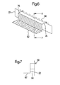
- Figures 6 and 7 show a third embodiment of the attachment of the measuring device 64.
- the support means 62 is articulated about a horizontal, but in the direction of travel and longitudinal direction of the longitudinal member 22 extending pivot axis 66.
- the support means 62 is rectangular and has a lower, horizontal leg which extends inwardly from the side rail 22, and a vertical leg extending upwardly on the inside of the horizontal leg, which in turn pivots about the pivot axis 66 by fasteners 76 on the side rail 22 is.
- the measuring device 64 is arranged between the vertical leg and the longitudinal member 22 and detects the torque exerted by the transport means 40, the structure of which corresponds to the embodiment shown in Figures 3 and 4, with the ball 18 disposed thereon on the support means 62.
- the support 62 may extend over the entire length of the range of motion of the conveyor 40 or a portion thereof.
- support members 62 provided with a measuring device 64 are arranged on both sides of the longitudinal members 22 so that measuring errors occurring on lateral slopes can be avoided.
- mechanically connect the support devices 62 on both sides of the machine 10 for example by means of a transverse strut arranged sufficiently far downwards, which makes it possible to drive over with the transport device 40. Then only a single measuring cell for the measuring device 64 is required. It can also, separate, along the direction of travel and / or working in the transverse direction inclination sensors are used to reduce the measurement error.
Abstract
Description
Die Erfindung betrifft eine Maschine zur Bildung und/oder Verarbeitung von Ballen, umfassend:
- eine Presskammer, in der Ballen aus Erntegut herstellbar sind,
- eine Vorrichtung zum Umwickeln der Ballen,
- eine Transporteinrichtung zum Transport der Ballen innerhalb der Maschine, die zwischen einer Ballenaufnahmeposition, in der sie
- einen in der Presskammer hergestellten Ballen aufnimmt, und einer Ballenumwicklungsposition bewegbar ist,
- und eine Vorrichtung zur Messung der Gewichtskraft eines Ballens, die eine Messeinrichtung zur Erfassung einer durch die Gewichtskraft des Ballens beeinflussten Messgröße aufweist.
- a press chamber in which bales can be produced from harvested material,
- a device for wrapping the bales,
- a transport means for transporting the bales within the machine between a bale picking position in which they
- receives a bale made in the bale chamber, and is movable to a bale wrapping position,
- and a device for measuring the weight of a bale, which has a measuring device for detecting a measured variable influenced by the weight of the bale.
Im Stand der Technik sind verschiedene Einrichtungen zur Messung der Masse eines Ballens aus gepresstem landwirtschaftlichem Erntegut bekannt.In the prior art, various means for measuring the mass of a bale of pressed agricultural crop are known.
Es wurde beispielsweise vorgeschlagen (DE 44 36 128 A, DE 198 35 163 A, US 4 742 880 A, US 5 384 436 A und US 5 742 010 A), einen fertiggestellten Ballen aus der Presskammer oder aus einer Wickelvorrichtung einer Pressen-Umwickler-Kombination (DE 199 10 555 A, US 6 457 295 B) hinauszufördern, auf eine Auflagefläche zu verbringen und dort bei einem sich im ruhenden oder bewegten Zustand befindlichen Ballen seine Gewichtskraft zu bestimmen, indem die Kraft erfasst wird, die er auf die Auflagefläche ausübt. Da die Ballen relativ hohe Massen haben, ist ein Anhalten schwer möglich, während eine Messung der Gewichtskraft bei bewegtem Ballen einem hohen Messfehler unterliegt.For example, it has been proposed (
In der DE 195 43 343 A wird vorgeschlagen, die an den Achsen und der Zugdeichsel einer Ballenpresse wirkenden Gewichtskräfte zu erfassen. Anhand der Änderung der Kräfte beim Auswerfen eines Ballens wird die Gewichtskraft des hergestellten Ballens berechnet. Es ist eine höhere Anzahl von Sensoren und eine ausgefeilte Rechentechnik erforderlich, um brauchbare Messwerte zu erhalten.DE 195 43 343 A proposes to detect the weight forces acting on the axles and the drawbar of a baling press. Based on the change of forces when ejecting a bale, the weight of the produced bale is calculated. It requires a higher number of sensors and a sophisticated computing technique to get usable readings.
Die US 5 866 855 A und die DE 27 34 562 A beschreiben Waagen für Fördergurte. In der GB 973 783 A wird vorgeschlagen, einlaufendes Fasermaterial in einen Behälter zu füllen, der dann, wenn das gemessene Gewicht des Behälters einem Sollgewicht entspricht, auf Schienen nach unten in eine Sammelposition gleitet.US 5 866 855 A and DE 27 34 562 A describe scales for conveyor belts. It is proposed in GB 973 783 A, incoming To fill fiber material in a container, which then, when the measured weight of the container corresponds to a target weight slides on rails down to a collection position.
Das der Erfindung zu Grunde liegende Problem wird darin gesehen, eine einfache und zuverlässige Messeinrichtung zur Erfassung der Gewichtskraft eines Ballens bereitzustellen, welche die oben erwähnten Nachteile nicht oder in einem verminderten Ausmaß aufweist.The problem underlying the invention is seen to provide a simple and reliable measuring device for detecting the weight of a bale, which does not have the disadvantages mentioned above or to a lesser extent.
Dieses Problem wird erfindungsgemäß durch die Lehre des Patentanspruchs 1 gelöst, wobei in den weiteren Patentansprüchen Merkmale aufgeführt sind, die die Lösung in vorteilhafter Weise weiterentwickeln.This problem is inventively solved by the teaching of claim 1, wherein in the other claims features are listed, which further develop the solution in an advantageous manner.
Eine Maschine zur Herstellung und/oder Verarbeitung von Ballen, ist eine Ballenpressen- und Ballenumwickler-Kombination und umfasst eine Transporteinrichtung, die eingerichtet ist, den Ballen von der Presskammer, in der der Ballen hergestellt wird, in die Wickelposition zu verbringen. Es wird vorgeschlagen, dass eine Messeinrichtung die Gewichtskraft des auf der Transporteinrichtung angeordneten Ballens erfasst. Auf diese Weise wird eine bereits vorhandene Transporteinrichtung zur Messung der Gewichtskraft des Ballens genutzt. Die Messeinrichtung kann an einer relativ geschützten Stelle der Maschine angeordnet werden.A bale making and / or processing machine is a baler and bale wrapper combination and includes a conveyor configured to transfer the bale from the baling chamber in which the bale is made to the wrapping position. It is proposed that a measuring device detects the weight of the bale arranged on the transport device. In this way, an existing transport device is used to measure the weight of the bale. The measuring device can be arranged at a relatively protected location of the machine.
Die Transporteinrichtung kann beliebiger Art sein. Es kann sich um einen verfahrbaren oder an einem beweglichen Gestänge angebrachten Schlitten handeln, auf dem der Ballen aufliegt. Es wäre zum Transport des Ballens auch ein beliebiger anderer, angetriebener Förderer denkbar, der beispielsweise einen Greifer, einen Fördergurt oder Förderwalzen aufweisen könnte. Die Transporteinrichtung kann aktiv angetrieben werden; der Ballen könnte aber auch nur durch die Schwerkraft transportiert werden, wenn ein hinreichender Höhenunterschied vorhanden ist.The transport device can be of any type. It may be a movable or mounted on a movable rod carriage on which rests the bale. It would be conceivable for transporting the bale also any other, driven conveyor, which could for example have a gripper, a conveyor belt or conveyor rollers. The transport device can be actively driven; but the bale could only be transported by gravity, if there is a sufficient difference in height.
Vorzugsweise stützt sich die Transporteinrichtung über Abstützelemente an einer mit der Maschine verbundenen Abstützeinrichtung ab. Die Abstützelemente bewegen sich mit der Transporteinrichtung entlang der Abstützeinrichtung, rollen beispielsweise an ihnen ab. Die Messeinrichtung ist zwischen der Abstützeinrichtung und der eigentlichen Maschine, z. B. ihrem Fahrgestell, angeordnet. Die Messeinrichtung erzeugt somit eine Information über die Gewichtskraft der Transporteinrichtung und des sich darauf befindenden Ballens. Die Gewichtskraft der Transporteinrichtung ist bekannt oder kann gemessen werden, so dass sich die Gewichtskraft des Ballens durch geeignete Rechenvorgänge ermitteln lässt. Ein Vorteil liegt darin, dass sich die Messeinrichtung nicht mit der Transporteinrichtung mitbewegen muss, was die Datenübertragung von der Messeinrichtung auf eine sich nicht mit der Transporteinrichtung mitbewegende Auswertungs-, Speicher- und/oder Anzeigeeinrichtung erleichtert.Preferably, the transport device is supported via support elements on a supporting device connected to the machine from. The support elements move with the transport device along the support means, for example, roll on them. The measuring device is between the support device and the actual machine, for. B. their chassis, arranged. The measuring device thus generates information about the weight of the transport device and the bale thereon. The weight of the transport device is known or can be measured, so that the weight of the bale can be determined by suitable calculations. One advantage is that the measuring device does not have to move with the transport device, which facilitates data transmission from the measuring device to an evaluation, storage and / or display device not moving with the transport device.
In einer bevorzugten Ausführungsform erstreckt sich die Abstützeinrichtung, bzw. ein mit der Messeinrichtung zusammenwirkender Teilbereich der Abstützeinrichtung, nur über einen Teil des Bewegungsbereichs der Transporteinrichtung. Die Gewichtskraft der Transporteinrichtung mit dem sich darauf befindlichen Ballen wird somit während des Transports erfasst, wobei die Transporteinrichtung zur Messung angehalten werden kann oder sich während der Messung weiterbewegt. In einer anderen Ausführungsform erstreckt sich die Abstützeinrichtung über den gesamten Bewegungsbereich der Transporteinrichtung.In a preferred embodiment, the support means, or a cooperating with the measuring device portion of the support means, only over a portion of the range of movement of the transport device. The weight of the transport device with the bale thereon is thus detected during transport, wherein the transport device can be stopped for measurement or moves on during the measurement. In another embodiment, the support means extends over the entire range of movement of the transport device.
Die Messeinrichtung kann eingerichtet sein, die Gewichtskraft, welche die Transporteinrichtung und der Ballen auf die Abstützeinrichtung ausüben, direkt zu messen. Dazu können an beiden Enden der Abstützeinrichtung oder an beliebigen Positionen dazwischen entsprechende Kraftmesszellen vorgesehen werden.The measuring device can be set up to directly measure the weight force which the transport device and the bale exert on the support device. For this purpose, corresponding force measuring cells can be provided at both ends of the support device or at arbitrary positions therebetween.
Alternativ erfasst die Messeinrichtung das Drehmoment, das die Transporteinrichtung und der Ballen erzeugen. Dazu ist die Abstützeinrichtung um eine horizontale Achse, die sich in der Regel quer zur Fahrtrichtung bzw. Bewegungsrichtung der Transporteinrichtung erstreckt, schwenkbar an der Maschine gelagert. Im Abstand von der Schwenkachse ist die Messeinrichtung zwischen der Abstützeinrichtung und der Maschine angeordnet. Durch die Messung des Drehmoments kann die Anzahl zu verwendender Kraftmesszellen verringert werden. So kann eine einzige Messzelle ausreichen, wenn die Abstützelemente auf beiden Seiten der Transporteinrichtung untereinander starr verbunden sind.Alternatively, the measuring device detects the torque that generate the transport device and the bale. For this purpose, the support device is pivotally mounted on the machine about a horizontal axis, which generally extends transversely to the direction of travel or direction of movement of the transport device. At a distance from the pivot axis is the measuring device placed between the support and the machine. By measuring the torque, the number of load cells to be used can be reduced. Thus, a single measuring cell may be sufficient if the supporting elements are rigidly connected to one another on both sides of the transport device.
In den Zeichnungen sind drei nachfolgend näher beschriebene Ausführungsbeispiele der Erfindung dargestellt. Es zeigt:
- Fig. 1
- eine schematische Seitenansicht einer Maschine zum Herstellen und Umwickeln von Ballen, die mit einer erfindungsgemäßen Vorrichtung zur Messung der Gewichtskraft der Ballen ausgestattet ist, wobei sich die Transporteinrichtung in einer Ballenempfangsposition befindet,
- Fig. 2
- eine Ansicht der Maschine aus Figur 1, in der sich die Transporteinrichtung in einer Ballenwickelposition befindet.
- Fig. 3
- einen Querschnitt durch die Maschine entlang der Linie 3-3 der Figur 1, in dem die Lagerung der Transporteinrichtung am Rahmen der Maschine dargestellt ist,
- Fig. 4
- eine schematische Seitenansicht der Lagerung der Transporteinrichtung am Rahmen der Maschine mit einer ersten Ausführungsform der Messeinrichtung,
- Fig. 5
- eine schematische Seitenansicht der Lagerung der Transporteinrichtung am Rahmen der Maschine mit einer zweiten Ausführungsform der Messeinrichtung,
- Fig. 6
- eine perspektivische Ansicht einer Lagerung der Transporteinrichtung am Rahmen der Maschine mit einer dritten Ausführungsform der Messeinrichtung, und
- Fig. 7
- einen Schnitt durch die
Lagerung der Figur 6 entlang der Linie 7-7.
- Fig. 1
- a schematic side view of a machine for producing and wrapping bales, which is equipped with a device according to the invention for measuring the weight of the bale, wherein the transport device is in a bale receiving position,
- Fig. 2
- a view of the machine of Figure 1, in which the transport device is in a bale wrapping position.
- Fig. 3
- a cross-section through the machine along the line 3-3 of Figure 1, in which the storage of the transport device is shown on the frame of the machine,
- Fig. 4
- a schematic side view of the storage of the transport device on the frame of the machine with a first embodiment of the measuring device,
- Fig. 5
- a schematic side view of the storage of the transport device on the frame of the machine with a second embodiment of the measuring device,
- Fig. 6
- a perspective view of a storage of the transport device on the frame of the machine with a third embodiment of the measuring device, and
- Fig. 7
- a section through the storage of Figure 6 along the line 7-7.
Die Figur 1 zeigt eine Seitenansicht einer Maschine 10 zum Herstellen und Umwickeln von Ballen. Sie umfasst eine Rundballenpresse 12, die auf einem Fahrgestell 14 angebracht ist, das außerdem eine Vorrichtung zum Umwickeln von Rundballen 16 mit Folie 20 trägt. Das Fahrgestell 14 umfasst zwei Längsträger 22, die sich an beiden Seiten der Maschine 10 in Vorwärtsfahrtrichtung erstrecken. Im vorderen Bereich der Längsträger 22 ist eine Tandemachse 24 angeordnet, die sich auf einem Paar vorderer Räder 26 und einem Paar hinterer Räder 28 abstützt. Die Maschine 10 wird durch eine Deichsel 32 mit einem Traktor verbunden, der sie über ein Feld zieht.FIG. 1 shows a side view of a
Die Rundballenpresse 12 ist an sich bekannter Bauart und kann Ballen aus Erntegut herstellen, das der Rundballenpresse 12 durch eine Pick-Up 30 zugeführt wird. Die Rundballenpresse 12 weist ein mit dem Fahrgestell 14 fest verbundenes vorderes Gehäuseteil 34 und ein um eine obere Schwenkachse 36 aufklappbares hinteres Gehäuseteil 38 auf. Beide Gehäuseteile 34, 38 bilden in geschlossenem Zustand einen variablen oder konstanten, nicht dargestellten Pressraum zur Herstellung von Rundballen. In Figur 1 ist das hintere Gehäuseteil 38 in aufgeklappter Stellung nach dem Auswurf eines Ballens 18 gezeigt.The
Der von der Rundballenpresse 12 erzeugte Ballen 18 rollt auf geeigneten Elementen aus dem vorderen Gehäuseteil 34 nach hinten hinaus und gelangt auf eine Transporteinrichtung 40, die eine vordere Walze 42 und eine hintere Walze 44 umfasst, um die eine Anzahl von seitlich nebeneinander angeordneten Transportbändern 46 umläuft, auf denen der Ballen 18 aufliegt. Die Transporteinrichtung 40 ist insgesamt zwischen der in Figur 1 dargestellten Ballenaufnahmeposition und der in Figur 2 gezeigten Ballenumwicklungsposition beweglich.The
Befindet sich der Ballen 18', wie in Figur 2 dargestellt, in der Ballenumwicklungsposition, wird er durch die Transporteinrichtung 40 um seine Zylinderachse 48 gedreht, indem die Walzen 42, 44 in an sich bekannter Weise durch geeignete Motoren in Drehung versetzt werden. Dabei wird der Ballen 18' durch eine um eine vertikale Achse 50 umlaufende, an einem Arm 54 befestigte Rolle mit der Folie 20 eingewickelt. Damit der folienumwickelte Ballen 18' nicht bei der Abgabe von der Transporteinrichtung aus relativ großer Höhe auf den Boden fällt, rollt der Ballen 18' schließlich auf einer Abrollvorrichtung 52 auf den Erdboden hinab. Wird das hintere Gehäuseteil 38 der Ballenpresse 12 nach oben geschwenkt, wird der Arm 54 aus Platzgründen nach hinten gedreht, wie in der Figur 1 dargestellt.If the bale 18 ', as shown in Figure 2, in the bale wrapping position, it is rotated by the
Die Anbringung der Transporteinrichtung 40 an den Längsträgern 22 ist in der Figur 3 detaillierter dargestellt, die einen Schnitt entlang der Linie 3-3 der Figur 1 zeigt. Die Walzen 42 und 44 sind drehbar an Trägern 56 gelagert, welche sich parallel zu den Längsträgern 22 erstrecken. Die beiden Träger 56 sind untereinander durch (nicht eingezeichnete) Querstreben verbunden und tragen jeweils vier (s. Figur 4 und 5) sich horizontal nach außen erstreckende Achsen 58, an denen Abstützelemente 60 in Form von Rädern drehbar gelagert sind. Die Abstützelemente 60 könnten auch starr mit den Achsen 58 verbunden sein, die dann wiederum drehbar an den Trägern 56 befestigt wären. An den Innenseiten der Längsträger 22 sind sich in Längsrichtung der Längsträger 22 erstreckende Abstützeinrichtungen 62 mit rechtwinkligem Profil angebracht, auf denen die Abstützelemente 60 abrollen.The attachment of the
Die Bewegung der Transporteinrichtung 40 zwischen den in Figur 1 und Figur 2 dargestellten Positionen kann durch einen in den Figuren nicht eingezeichneten Hydraulikzylinder oder einen anderen Motor bewerkstelligt werden. Es wäre für diesen Zweck auch ein Rotations-Antrieb der Abstützelemente 60 denkbar. Der Antrieb der Walzen 42, 44 kann durch einen an den Trägern 56 angebrachten Hydromotor erfolgen. Es sind auch Ausführungsformen der Maschine 10 denkbar, bei denen sich ein rotativer Antrieb der Walzen 42, 44 erübrigt.The movement of the
Die Figur 4 zeigt eine erste Ausführungsform einer Messeinrichtung 64 zur Erfassung der Gewichtskraft bzw. Masse des Ballens 18. Die Abstützeinrichtungen 62 sind in Teilbereiche 70, 72, 74 unterteilt. Vor und hinter einem mittleren Teilbereich 72 der Abstützeinrichtung 62 ist ein vorderer Teilbereich 70 und ein hinterer Teilbereich 74 der Abstützvorrichtung 62 vorhanden. Diese vorderen und hinteren Teilbereiche 70, 74 der Abstützvorrichtung 62 sind starr mit dem Längsträger 22 verbunden.FIG. 4 shows a first embodiment of a measuring
Der mittlere Teilbereich 72 der Abstützeinrichtung 62 hat eine Länge, die etwas größer als der Abstand der Achsen 58 ist, und ist an einem ersten (vorderen oder hinteren) Ende um eine horizontal und quer zur Fahrtrichtung verlaufende Schwenkachse 66 schwenkbar am Längsträger 22 angelenkt, ansonsten aber frei beweglich. Er stützt sich über die Messeinrichtung 64 auf einer vom Längsträger 22 nach innen ragenden Konsole 68 ab. Befinden sich beide Abstützelemente 60 der Transporteinrichtung 40 somit oberhalb der Abstützeinrichtung 62, erzeugen sie an der Schwenkachse 58 ein Drehmoment, das in der Messeinrichtung 64 eine Kraft erzeugt, die durch die Messeinrichtung 64 erfasst und einer (nicht dargestellten) Auswertungseinrichtung zugeführt wird. Durch Vergleich mit dem Messwert einer leeren Transporteinrichtung 40 kann die Gewichtskraft des Ballens 18 ermittelt werden.The
Der Auswertungseinrichtung kann auch ein Messwert eines Sensors zugeführt werden, welcher die Position der Transporteinrichtung 40 erfasst oder beim Erreichen einer vorbestimmten Position ein Signal abgibt, so dass eine Information vorliegt, an welcher Stelle der Abstützeinrichtung 62 sich die Transporteinrichtung 40 jeweils befindet. Diese Information könnte aber auch aus den Signalen der Messeinrichtung 64 abgeleitet werden. Die Transporteinrichtung 40 kann zur Messung gestoppt werden, wobei zwecks einer Verbesserung der Messgenauigkeit beim Überfahren unebenen Geländes eine Erfassung der Messwerte der Messeinrichtung 64 für eine längere Zeit und eine Mittelwertbildung erfolgen kann. Alternativ wird die Transporteinrichtung 40 kontinuierlich bewegt und aus den zeitabhängig ermittelten und abgespeicherten Messwerten, die vorzugsweise mit der erwähnten Information über die Position der Transporteinrichtung kombiniert werden, durch eine Recheneinrichtung die Gewichtskraft abgeleitet. Auf diese Weise wird die Gewichtskraft des Ballens 18 bestimmt. Sie wird vorzugsweise mittels einer Anzeigevorrichtung in der Kabine des Traktors zur Anzeige gebracht und auf einer portablen Speichereinrichtung abgespeichert.The evaluation device can also be supplied with a measured value of a sensor which detects the position of the
Die Messeinrichtung 64 könnte mit der Lagerung der Abstützeinrichtung 62 an der Schwenkachse 66 gemeinsam in einem schützenden Gehäuse angeordnet werden, da sie sich relativ nahe an der Schwenkachse 66 befindet. In einer anderen Ausführungsform könnte die Messeinrichtung 64 aber auch an dem von der Schwenkachse 66 abgewandten Ende der Abstützeinrichtung 62 angeordnet sein.The measuring
Die Figur 5 zeigt die Anbringung der Messeinrichtung 64 in einer anderen Ausführungsform der Erfindung. Hier erstreckt sich die Abstützeinrichtung 62 über den gesamten Bewegungsbereich der Transporteinrichtung 40. Die Abstützeinrichtung 62 ist an einem (hinteren oder vorderen) Ende um eine horizontal und quer zur Fahrtrichtung verlaufende Schwenkachse 66 schwenkbar am Längsträger 22 befestigt und stützt sich am anderen Ende (oder an einer beliebigen anderen Stelle entlang der Abstützeinrichtung 62) über die Messeinrichtung 64 und die Konsole 68 am Längsträger 22 ab. Auch hier erfasst die Messeinrichtung 64 das von der Transporteinrichtung 40 erzeugte und von der Gewichtskraft des Ballens 18 erzeugte Drehmoment, wobei die weitere Auswertung wie oben beschrieben erfolgen kann.FIG. 5 shows the attachment of the measuring
Bei den beiden dargestellten Ausführungsformen könnten im Übrigen an beiden Enden der Abstützeinrichtung 62 Messeinrichtungen 64 angeordnet sein, um anstelle des Drehmoments die Gewichtskraft der Transporteinrichtung 40 und des darauf angeordneten Ballens 18 zu erfassen.Incidentally, in the two embodiments shown, measuring
Schließlich zeigen die Figuren 6 und 7 eine dritte Ausführungsform der Anbringung der Messeinrichtung 64. Am Längsträger 22 ist die Abstützeinrichtung 62 um eine horizontale, sich jedoch in Fahrtrichtung und Längsrichtung des Längsträgers 22 erstreckende Schwenkachse 66 angelenkt. Die Abstützeinrichtung 62 ist rechtwinklig und hat einen unteren, horizontalen Schenkel, der sich vom Längsträger 22 nach innen erstreckt, sowie einen an der Innenseite des horizontalen Schenkels nach oben erstreckenden vertikalen Schenkel, der wiederum durch Verbindungselemente 76 am Längsträger 22 um die Schwenkachse 66 schwenkbar angelenkt ist. Die Messeinrichtung 64 ist zwischen dem vertikalen Schenkel und dem Längsträger 22 angeordnet und erfasst das Drehmoment, das die Transporteinrichtung 40, deren Aufbau der in Figur 3 und 4 gezeigten Ausführungsform entspricht, mit dem darauf angeordneten Ballen 18 auf die Abstützeinrichtung 62 ausübt. Die Abstützeinrichtung 62 kann sich über die gesamte Länge des Bewegungsbereichs der Transporteinrichtung 40 oder einen Teilbereich davon erstrecken.Finally, Figures 6 and 7 show a third embodiment of the attachment of the measuring
In der Regel sind an beiden Seiten der Längsträger 22 mit einer Messeinrichtung 64 versehene Abstützeinrichtungen 62 angeordnet, so dass an seitlichen Hängen auftretende Messfehler vermieden werden können. Es wäre aber auch denkbar, die Abstützeinrichtungen 62 auf beiden Seiten der Maschine 10 mechanisch zu verbinden, beispielsweise durch eine hinreichend weit unten angeordnete Querstrebe, die ein Überfahren mit der Transporteinrichtung 40 ermöglicht. Dann ist nur eine einzige Messzelle für die Messeinrichtung 64 erforderlich. Es können auch separate, entlang der Fahrtrichtung und/oder in Querrichtung arbeitende Neigungssensoren zu einer Verminderung der Messfehler verwendet werden.As a rule,
Claims (7)
- A machine for forming and/or processing bales (18), comprising:a compaction chamber (12) in which bales (18) of harvested crop can be produced,a device (16) for wrapping the bales (18),a transport device (40) for transporting the bales (18) within the machine (10), movable between a bale receiving position, in which it receives a bale (18) formed in the compaction chamber, and a bale wrapping position,and a device for measuring the weight of a bale (18) which comprises a measuring device (64) for detecting a measured quantity influenced by the weight of the bale (18),characterized in that the measuring device (64) is arranged to detect the weight of a bale disposed on the transport device (40).
- A machine (10) according to claim 1, characterized in that the transport device (40) comprises a carriage which can be traversed and/or is fitted on a movable linkage, on which the bale rests, and/or a gripper, a conveyor belt or conveyor rollers.
- A machine (10) according to claim 1 or 2, characterized in that the transport device (40) is supported by support elements (60) on a support device (62) connected to the machine (10), in that the support elements (60) move relative to the support device (62) during movement of the transport device (40), and in that the measuring device (64) is arranged between the support device (62) and the machine (10).
- A machine (10) according to claim 3, characterized in that the support device (62) extends over a partial region (72) only of the range of movement of the transport device (40).
- A machine (10) according to claim 3, characterized in that the support device (62) extends over the whole range of movement of the transport device (40).
- A machine (10) according to any of claims 3 to 5, characterized in that the measuring device (64) is arranged to detect the weight imposed on the support device (62) by the transport device (40) and the bale (18) present thereon.
- A machine (10) according to any of claims 3 to 5, characterized in that the support device (62) is mounted pivotally about a horizontal axis (66) on the machine (10) and in that the measuring device (64) is arranged to detect a moment exerted on the support device (62) by the transport device (40) and the bale (18) present thereon.
Applications Claiming Priority (2)
| Application Number | Priority Date | Filing Date | Title |
|---|---|---|---|
| DE10322333 | 2003-05-17 | ||
| DE10322333A DE10322333A1 (en) | 2003-05-17 | 2003-05-17 | Device for measuring the weight of a bale |
Publications (2)
| Publication Number | Publication Date |
|---|---|
| EP1480025A1 EP1480025A1 (en) | 2004-11-24 |
| EP1480025B1 true EP1480025B1 (en) | 2006-11-22 |
Family
ID=33039189
Family Applications (1)
| Application Number | Title | Priority Date | Filing Date |
|---|---|---|---|
| EP04101781A Expired - Lifetime EP1480025B1 (en) | 2003-05-17 | 2004-04-28 | Device for determining the weight of a bale |
Country Status (5)
| Country | Link |
|---|---|
| US (1) | US7091425B2 (en) |
| EP (1) | EP1480025B1 (en) |
| AT (1) | ATE346283T1 (en) |
| CA (1) | CA2467376A1 (en) |
| DE (2) | DE10322333A1 (en) |
Cited By (1)
| Publication number | Priority date | Publication date | Assignee | Title |
|---|---|---|---|---|
| CN100483085C (en) * | 2007-07-23 | 2009-04-29 | 南京三埃测控有限公司 | Bulk material high precision belt weighing array system |
Families Citing this family (18)
| Publication number | Priority date | Publication date | Assignee | Title |
|---|---|---|---|---|
| DE102006011135A1 (en) * | 2006-03-10 | 2007-09-20 | Deere & Company, Moline | control device |
| EP2090153B1 (en) * | 2008-02-13 | 2015-09-09 | Usines CLAAS France S.A.S. | Round baler |
| US7805914B2 (en) * | 2008-03-10 | 2010-10-05 | Cnh America Llc | Hydraulic bale kicker with optional weighing device |
| NL1037742C2 (en) * | 2010-02-23 | 2011-08-24 | Forage Innovations Bv | Wrapper for wrapping bales of crop material. |
| NL1037740C2 (en) * | 2010-02-23 | 2011-08-24 | Forage Innovations Bv | Wrapper for wrapping round bales of crop material. |
| CN102279099B (en) * | 2011-04-01 | 2013-05-08 | 江苏大学 | Straw compression forming and bundling test device and method |
| CA2795057A1 (en) * | 2011-11-04 | 2013-05-04 | Les Tourbieres Berger Ltee | Method and system for palletizing peat moss |
| US9297688B2 (en) | 2012-12-21 | 2016-03-29 | Cnh Industrial America Llc | Weighing round bales |
| EP3036986B1 (en) * | 2014-12-24 | 2019-10-16 | CNH Industrial Belgium nv | Weighing round bales |
| CN104695029B (en) * | 2015-03-16 | 2017-03-01 | 中国农业科学院麻类研究所 | A kind of control system of a feed-type decorticator and control device |
| CH712367A1 (en) * | 2016-04-15 | 2017-10-31 | Rieter Ag Maschf | Method for calibrating the support force of a removal organ of a bale opener and bale opener. |
| US10091943B2 (en) | 2016-09-06 | 2018-10-09 | Deere & Company | Round module weighing using differential pressure sensing |
| DE102017215438A1 (en) | 2017-09-04 | 2019-03-07 | Deere & Company | Weighing device and harvesting device |
| US10925217B2 (en) | 2017-10-02 | 2021-02-23 | Deere & Company | Baler with dry matter content detection system |
| US10945378B2 (en) * | 2017-10-02 | 2021-03-16 | Deere & Company | Method of controlling bale size based on bale weight |
| US11051456B2 (en) | 2019-01-02 | 2021-07-06 | Deere & Company | Bale weight measurement and control system using liftgate |
| US11825775B2 (en) | 2020-07-20 | 2023-11-28 | Deere & Company | Round baler with bale holder in gate |
| US11771010B2 (en) | 2020-07-20 | 2023-10-03 | Deere & Company | Round baler with position controlled take-up roller, and method of operating a round baler |
Family Cites Families (10)
| Publication number | Priority date | Publication date | Assignee | Title |
|---|---|---|---|---|
| GB973783A (en) * | 1962-10-25 | 1964-10-28 | Central Line Sisal Estates Ltd | Apparatus for packing and weighing fibrous material |
| DE2734562A1 (en) * | 1977-07-30 | 1979-02-08 | Schenck Ag Carl | Monitored operation of conveyor type weigher - weighs goods at input and output of weighing bridge, and trips signal when difference exceeds set value |
| US4362097A (en) * | 1980-12-29 | 1982-12-07 | Rogers Laurence J D | Apparatus for determining weight of cylindrical hay bales |
| US4742880A (en) | 1987-04-15 | 1988-05-10 | Hesston Corporation | Method and apparatus for determining the weight of bales issuing from a crop baler |
| US5384436A (en) | 1993-06-30 | 1995-01-24 | Pritchard; Gary E. | Apparatus and method for electrically weighing bales in a mobile crop baler |
| DE4436128A1 (en) | 1994-09-27 | 1996-03-28 | Claas Ohg | Weighing device for balers |
| DE19543343C5 (en) | 1995-11-22 | 2007-01-18 | Claas Kgaa Mbh | Agricultural Baler |
| US5742010A (en) | 1996-08-28 | 1998-04-21 | Griffin; Thomas J. | Hay baler scale |
| US5866855A (en) * | 1997-07-22 | 1999-02-02 | Engineering Services And Systems, Inc. | General purpose belt scale |
| DE19910555A1 (en) | 1999-03-10 | 2000-09-14 | Lely Welger Maschinenfabrik Gm | Agricultural round baler with a weighing device |
-
2003
- 2003-05-17 DE DE10322333A patent/DE10322333A1/en not_active Withdrawn
-
2004
- 2004-04-28 AT AT04101781T patent/ATE346283T1/en not_active IP Right Cessation
- 2004-04-28 DE DE502004002051T patent/DE502004002051D1/en not_active Expired - Lifetime
- 2004-04-28 EP EP04101781A patent/EP1480025B1/en not_active Expired - Lifetime
- 2004-05-17 CA CA002467376A patent/CA2467376A1/en not_active Abandoned
- 2004-05-17 US US10/847,189 patent/US7091425B2/en not_active Expired - Fee Related
Cited By (1)
| Publication number | Priority date | Publication date | Assignee | Title |
|---|---|---|---|---|
| CN100483085C (en) * | 2007-07-23 | 2009-04-29 | 南京三埃测控有限公司 | Bulk material high precision belt weighing array system |
Also Published As
| Publication number | Publication date |
|---|---|
| US7091425B2 (en) | 2006-08-15 |
| DE10322333A1 (en) | 2004-12-02 |
| US20040245028A1 (en) | 2004-12-09 |
| CA2467376A1 (en) | 2004-11-17 |
| DE502004002051D1 (en) | 2007-01-04 |
| ATE346283T1 (en) | 2006-12-15 |
| EP1480025A1 (en) | 2004-11-24 |
Similar Documents
| Publication | Publication Date | Title |
|---|---|---|
| EP1480025B1 (en) | Device for determining the weight of a bale | |
| EP1034695B1 (en) | Agricultural round baler with a weighing device | |
| EP1396187B1 (en) | Rotobaler with weighing device | |
| EP1795065B1 (en) | Baler with moisture measuring device | |
| EP1029440A1 (en) | Agricultural baler with a weighing device | |
| EP1516527B1 (en) | Baller | |
| EP0978230B1 (en) | Method and device for determining the pressing density of bales | |
| EP1480024B1 (en) | Device for measuring the weight of a load | |
| EP3106020B1 (en) | Round baler with a sensor for measuring bale size | |
| DE19835163C1 (en) | Method and device for determining the actual weight of bales | |
| DE19919322A1 (en) | Bale wrapper | |
| DE19606601C2 (en) | Device for picking up root crops with at least one conveyor | |
| EP4085747B1 (en) | Harvester with position-related weight determination taking into account an operating state and method for the same | |
| EP3449718A1 (en) | Weighing device and harvesting device | |
| EP3081072B1 (en) | Device for wrapping bales of harvested agricultural produce | |
| DE4427901C2 (en) | Device for loading containers | |
| DE4012740C1 (en) | Pick-up and compression machine for agricultural crops - has differential indicators, associated with two bale size indicators | |
| EP0248371B1 (en) | Machine for filling bags | |
| DE10338349A1 (en) | Round ball press with weighing platform for weighing the prepared balls and a brake for slowing or stopping the ball on the platform until it has been weighed | |
| DE10001594C2 (en) | Mobile vehicle weighing device and method for mobile weighing of vehicles | |
| DE102008050561A1 (en) | Loading wagon for collecting and transporting harvested material, has harvested material storage for storing harvested material, and displaceable limiting plate to limit loading chamber in harvested material storage |
Legal Events
| Date | Code | Title | Description |
|---|---|---|---|
| PUAI | Public reference made under article 153(3) epc to a published international application that has entered the european phase |
Free format text: ORIGINAL CODE: 0009012 |
|
| AK | Designated contracting states |
Kind code of ref document: A1 Designated state(s): AT BE BG CH CY CZ DE DK EE ES FI FR GB GR HU IE IT LI LU MC NL PL PT RO SE SI SK TR |
|
| AX | Request for extension of the european patent |
Extension state: AL HR LT LV MK |
|
| 17P | Request for examination filed |
Effective date: 20050524 |
|
| AKX | Designation fees paid |
Designated state(s): AT BE BG CH CY CZ DE DK EE ES FI FR GB GR HU IE IT LI LU MC NL PL PT RO SE SI SK TR |
|
| GRAP | Despatch of communication of intention to grant a patent |
Free format text: ORIGINAL CODE: EPIDOSNIGR1 |
|
| GRAS | Grant fee paid |
Free format text: ORIGINAL CODE: EPIDOSNIGR3 |
|
| GRAA | (expected) grant |
Free format text: ORIGINAL CODE: 0009210 |
|
| AK | Designated contracting states |
Kind code of ref document: B1 Designated state(s): AT BE BG CH CY CZ DE DK EE ES FI FR GB GR HU IE IT LI LU MC NL PL PT RO SE SI SK TR |
|
| PG25 | Lapsed in a contracting state [announced via postgrant information from national office to epo] |
Ref country code: IT Free format text: LAPSE BECAUSE OF FAILURE TO SUBMIT A TRANSLATION OF THE DESCRIPTION OR TO PAY THE FEE WITHIN THE PRESCRIBED TIME-LIMIT;WARNING: LAPSES OF ITALIAN PATENTS WITH EFFECTIVE DATE BEFORE 2007 MAY HAVE OCCURRED AT ANY TIME BEFORE 2007. THE CORRECT EFFECTIVE DATE MAY BE DIFFERENT FROM THE ONE RECORDED. Effective date: 20061122 Ref country code: FI Free format text: LAPSE BECAUSE OF FAILURE TO SUBMIT A TRANSLATION OF THE DESCRIPTION OR TO PAY THE FEE WITHIN THE PRESCRIBED TIME-LIMIT Effective date: 20061122 Ref country code: PL Free format text: LAPSE BECAUSE OF FAILURE TO SUBMIT A TRANSLATION OF THE DESCRIPTION OR TO PAY THE FEE WITHIN THE PRESCRIBED TIME-LIMIT Effective date: 20061122 Ref country code: CZ Free format text: LAPSE BECAUSE OF FAILURE TO SUBMIT A TRANSLATION OF THE DESCRIPTION OR TO PAY THE FEE WITHIN THE PRESCRIBED TIME-LIMIT Effective date: 20061122 Ref country code: RO Free format text: LAPSE BECAUSE OF FAILURE TO SUBMIT A TRANSLATION OF THE DESCRIPTION OR TO PAY THE FEE WITHIN THE PRESCRIBED TIME-LIMIT Effective date: 20061122 Ref country code: SI Free format text: LAPSE BECAUSE OF FAILURE TO SUBMIT A TRANSLATION OF THE DESCRIPTION OR TO PAY THE FEE WITHIN THE PRESCRIBED TIME-LIMIT Effective date: 20061122 Ref country code: SK Free format text: LAPSE BECAUSE OF FAILURE TO SUBMIT A TRANSLATION OF THE DESCRIPTION OR TO PAY THE FEE WITHIN THE PRESCRIBED TIME-LIMIT Effective date: 20061122 |
|
| REG | Reference to a national code |
Ref country code: GB Ref legal event code: FG4D Free format text: NOT ENGLISH |
|
| REG | Reference to a national code |
Ref country code: CH Ref legal event code: EP |
|
| REG | Reference to a national code |
Ref country code: IE Ref legal event code: FG4D Free format text: LANGUAGE OF EP DOCUMENT: GERMAN |
|
| REF | Corresponds to: |
Ref document number: 502004002051 Country of ref document: DE Date of ref document: 20070104 Kind code of ref document: P |
|
| PG25 | Lapsed in a contracting state [announced via postgrant information from national office to epo] |
Ref country code: DK Free format text: LAPSE BECAUSE OF FAILURE TO SUBMIT A TRANSLATION OF THE DESCRIPTION OR TO PAY THE FEE WITHIN THE PRESCRIBED TIME-LIMIT Effective date: 20070222 Ref country code: SE Free format text: LAPSE BECAUSE OF FAILURE TO SUBMIT A TRANSLATION OF THE DESCRIPTION OR TO PAY THE FEE WITHIN THE PRESCRIBED TIME-LIMIT Effective date: 20070222 Ref country code: BG Free format text: LAPSE BECAUSE OF FAILURE TO SUBMIT A TRANSLATION OF THE DESCRIPTION OR TO PAY THE FEE WITHIN THE PRESCRIBED TIME-LIMIT Effective date: 20070222 |
|
| PG25 | Lapsed in a contracting state [announced via postgrant information from national office to epo] |
Ref country code: ES Free format text: LAPSE BECAUSE OF FAILURE TO SUBMIT A TRANSLATION OF THE DESCRIPTION OR TO PAY THE FEE WITHIN THE PRESCRIBED TIME-LIMIT Effective date: 20070305 |
|
| PG25 | Lapsed in a contracting state [announced via postgrant information from national office to epo] |
Ref country code: PT Free format text: LAPSE BECAUSE OF FAILURE TO SUBMIT A TRANSLATION OF THE DESCRIPTION OR TO PAY THE FEE WITHIN THE PRESCRIBED TIME-LIMIT Effective date: 20070423 |
|
| GBV | Gb: ep patent (uk) treated as always having been void in accordance with gb section 77(7)/1977 [no translation filed] |
Effective date: 20061122 |
|
| EN | Fr: translation not filed | ||
| PLBE | No opposition filed within time limit |
Free format text: ORIGINAL CODE: 0009261 |
|
| STAA | Information on the status of an ep patent application or granted ep patent |
Free format text: STATUS: NO OPPOSITION FILED WITHIN TIME LIMIT |
|
| 26N | No opposition filed |
Effective date: 20070823 |
|
| PG25 | Lapsed in a contracting state [announced via postgrant information from national office to epo] |
Ref country code: GB Free format text: LAPSE BECAUSE OF FAILURE TO SUBMIT A TRANSLATION OF THE DESCRIPTION OR TO PAY THE FEE WITHIN THE PRESCRIBED TIME-LIMIT Effective date: 20061122 |
|
| BERE | Be: lapsed |
Owner name: DEERE & CY Effective date: 20070430 |
|
| PG25 | Lapsed in a contracting state [announced via postgrant information from national office to epo] |
Ref country code: BE Free format text: LAPSE BECAUSE OF NON-PAYMENT OF DUE FEES Effective date: 20070430 |
|
| PG25 | Lapsed in a contracting state [announced via postgrant information from national office to epo] |
Ref country code: GR Free format text: LAPSE BECAUSE OF FAILURE TO SUBMIT A TRANSLATION OF THE DESCRIPTION OR TO PAY THE FEE WITHIN THE PRESCRIBED TIME-LIMIT Effective date: 20070223 Ref country code: FR Free format text: LAPSE BECAUSE OF FAILURE TO SUBMIT A TRANSLATION OF THE DESCRIPTION OR TO PAY THE FEE WITHIN THE PRESCRIBED TIME-LIMIT Effective date: 20070713 |
|
| PGFP | Annual fee paid to national office [announced via postgrant information from national office to epo] |
Ref country code: AT Payment date: 20080402 Year of fee payment: 5 |
|
| PG25 | Lapsed in a contracting state [announced via postgrant information from national office to epo] |
Ref country code: FR Free format text: LAPSE BECAUSE OF FAILURE TO SUBMIT A TRANSLATION OF THE DESCRIPTION OR TO PAY THE FEE WITHIN THE PRESCRIBED TIME-LIMIT Effective date: 20061122 |
|
| REG | Reference to a national code |
Ref country code: CH Ref legal event code: PL |
|
| NLV4 | Nl: lapsed or anulled due to non-payment of the annual fee |
Effective date: 20081101 |
|
| PG25 | Lapsed in a contracting state [announced via postgrant information from national office to epo] |
Ref country code: EE Free format text: LAPSE BECAUSE OF FAILURE TO SUBMIT A TRANSLATION OF THE DESCRIPTION OR TO PAY THE FEE WITHIN THE PRESCRIBED TIME-LIMIT Effective date: 20061122 Ref country code: NL Free format text: LAPSE BECAUSE OF NON-PAYMENT OF DUE FEES Effective date: 20081101 Ref country code: LI Free format text: LAPSE BECAUSE OF NON-PAYMENT OF DUE FEES Effective date: 20080430 Ref country code: CH Free format text: LAPSE BECAUSE OF NON-PAYMENT OF DUE FEES Effective date: 20080430 |
|
| PG25 | Lapsed in a contracting state [announced via postgrant information from national office to epo] |
Ref country code: MC Free format text: LAPSE BECAUSE OF NON-PAYMENT OF DUE FEES Effective date: 20070430 |
|
| PG25 | Lapsed in a contracting state [announced via postgrant information from national office to epo] |
Ref country code: CY Free format text: LAPSE BECAUSE OF FAILURE TO SUBMIT A TRANSLATION OF THE DESCRIPTION OR TO PAY THE FEE WITHIN THE PRESCRIBED TIME-LIMIT Effective date: 20061122 Ref country code: LU Free format text: LAPSE BECAUSE OF NON-PAYMENT OF DUE FEES Effective date: 20070428 |
|
| PG25 | Lapsed in a contracting state [announced via postgrant information from national office to epo] |
Ref country code: TR Free format text: LAPSE BECAUSE OF FAILURE TO SUBMIT A TRANSLATION OF THE DESCRIPTION OR TO PAY THE FEE WITHIN THE PRESCRIBED TIME-LIMIT Effective date: 20061122 Ref country code: HU Free format text: LAPSE BECAUSE OF FAILURE TO SUBMIT A TRANSLATION OF THE DESCRIPTION OR TO PAY THE FEE WITHIN THE PRESCRIBED TIME-LIMIT Effective date: 20070523 |
|
| PG25 | Lapsed in a contracting state [announced via postgrant information from national office to epo] |
Ref country code: AT Free format text: LAPSE BECAUSE OF NON-PAYMENT OF DUE FEES Effective date: 20090428 |
|
| PGFP | Annual fee paid to national office [announced via postgrant information from national office to epo] |
Ref country code: DE Payment date: 20190320 Year of fee payment: 16 Ref country code: IE Payment date: 20190429 Year of fee payment: 16 |
|
| REG | Reference to a national code |
Ref country code: DE Ref legal event code: R119 Ref document number: 502004002051 Country of ref document: DE |
|
| PG25 | Lapsed in a contracting state [announced via postgrant information from national office to epo] |
Ref country code: DE Free format text: LAPSE BECAUSE OF NON-PAYMENT OF DUE FEES Effective date: 20201103 |
|
| PG25 | Lapsed in a contracting state [announced via postgrant information from national office to epo] |
Ref country code: IE Free format text: LAPSE BECAUSE OF NON-PAYMENT OF DUE FEES Effective date: 20200428 |