EP1479998A2 - Verstellbare halterung für ein halfter - Google Patents
Verstellbare halterung für ein halfter Download PDFInfo
- Publication number
- EP1479998A2 EP1479998A2 EP04425353A EP04425353A EP1479998A2 EP 1479998 A2 EP1479998 A2 EP 1479998A2 EP 04425353 A EP04425353 A EP 04425353A EP 04425353 A EP04425353 A EP 04425353A EP 1479998 A2 EP1479998 A2 EP 1479998A2
- Authority
- EP
- European Patent Office
- Prior art keywords
- holster
- seating
- connection plate
- loop attachment
- arm
- Prior art date
- Legal status (The legal status is an assumption and is not a legal conclusion. Google has not performed a legal analysis and makes no representation as to the accuracy of the status listed.)
- Granted
Links
Images

Classifications
-
- F—MECHANICAL ENGINEERING; LIGHTING; HEATING; WEAPONS; BLASTING
- F41—WEAPONS
- F41C—SMALLARMS, e.g. PISTOLS, RIFLES; ACCESSORIES THEREFOR
- F41C33/00—Means for wearing or carrying smallarms
- F41C33/02—Holsters, i.e. cases for pistols having means for being carried or worn, e.g. at the belt or under the arm
- F41C33/04—Special attachments therefor
- F41C33/041—Special attachments therefor for connecting a holster to a belt, webbing or other object
- F41C33/045—Special attachments therefor for connecting a holster to a belt, webbing or other object for connection in more than one rotational position around an axle, e.g. by using a rotatable connection
-
- A—HUMAN NECESSITIES
- A45—HAND OR TRAVELLING ARTICLES
- A45F—TRAVELLING OR CAMP EQUIPMENT: SACKS OR PACKS CARRIED ON THE BODY
- A45F5/00—Holders or carriers for hand articles; Holders or carriers for use while travelling or camping
- A45F5/02—Fastening articles to the garment
-
- A—HUMAN NECESSITIES
- A45—HAND OR TRAVELLING ARTICLES
- A45F—TRAVELLING OR CAMP EQUIPMENT: SACKS OR PACKS CARRIED ON THE BODY
- A45F5/00—Holders or carriers for hand articles; Holders or carriers for use while travelling or camping
- A45F5/02—Fastening articles to the garment
- A45F5/021—Fastening articles to the garment to the belt
-
- A—HUMAN NECESSITIES
- A45—HAND OR TRAVELLING ARTICLES
- A45F—TRAVELLING OR CAMP EQUIPMENT: SACKS OR PACKS CARRIED ON THE BODY
- A45F5/00—Holders or carriers for hand articles; Holders or carriers for use while travelling or camping
- A45F5/02—Fastening articles to the garment
- A45F2005/025—Fastening articles to the garment with a holder or item rotatably connected to the fastening device, e.g. having a rotation axis perpendicular to the garment
- A45F2005/027—Fastening articles to the garment with a holder or item rotatably connected to the fastening device, e.g. having a rotation axis perpendicular to the garment with a horizontal and parallel rotation axis, i.e. the axis being parallel to the surface of the garment
Definitions
- the present invention generally relates to the field of professional accessories issued to police officers, military men, armed surveillance services and the like. More particularly, the invention relates to an adjustable holster securement device of an improved type for securing a holster to a user belt and allowing adjustable positioning of the holster to improve its comfort, effectiveness and safety in use.
- a holster securement device of the known type that makes it possible to adjust the inclination of the holster is disclosed in Italian Patent Application No. FI20001A000090.
- the holster securement device in accordance with this patent application comprises a loop portion engageable with the user's belt, a connection portion inclined with respect to said loop portion and a base extending at the free end of said connection portion and having a disc member to which the holster can be pivotally secured.
- a row of equally spaced pins extends along the edge of the disc member from one of its faces and a tooth may be snap fit engaged in the spaces between any chosen pair of said pins, thus preventing any further possibility of rotation to occur.
- the tooth is connected to a sliding arm and it is possible to disengage the tooth from the pins by pressing the end of the arm to allow the disc member to be freely rotated up to find the desired angular position of the holster.
- the holster securement device in accordance with the cited patent application also permits regulation of the height of the holster, i.e. the distance of the holster from the belt, because the disc member for adjusting the inclination of the holster is fixed to a sliding plate mounted on the base of the holster securement device and capable of being arranged into at least two position in which the holster is at different distances from the belt. In this way the distance of the holster from the belt can be adjusted, but this is obtained by increasing the thickness, and therefore the encumbrance, of the holster securement device.
- the entire holster securement device has to be left attached to the user's belt even after the holster has been removed and this becomes bothersome and uncomfortable due to the encumbrance of the securement device.
- a holster securement device in which a double-jointed connection is provided between the loop attachment and the base to which the holster is secured is disclosed in Italian patent application no. PI2001A000082.
- This connection is constituted by a substantially double-T shaped joint hinged both to the loop attachment and the base of the holster securement device.
- this adjustment can only be carried out by using a tool to act on the screws that lock the two hinges.
- the regulation is therefore laborious and problematical every time it has to be carried out and an appropriate tool is not available.
- the object of the present invention is to provide an adjustable holster securement device of an improved type by means of which all the aforementioned drawbacks associated with holster securement devices of the known type can be overcome.
- Another object of the present invention is to provide a holster securement device of the aforementioned type in which the adjustment of the distance of the holster from the point of attachment to the belt can be obtained without penalizing the dimensions of the device.
- a further object of the present invention is to provide a holster securement device of the aforementioned type in which the dimension of the portion thereof that remains attached to the belt when the holster containing the weapon is not worn is very low.
- Yet another object of the present invention is to provide a holster securement device of the aforementioned type in which there is provided a system for adjusting the inclination of the holster by means of a locking device that is readily accessible and assures an adequate stability of the chosen position even when the user is bumped.
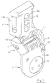
- the improved adjustable holster securement device in accordance with the present invention comprising an articulated joint to provide a connection between the loop attachment and the holster connection plate, said joint being formed by two opposedly arranged, substantially U-shaped members pivotably engaged in respective seatings, the two pairs of seatings being coaxial and parallel and integral with, respectively, said loop attachment and said connection plate, and comprises also tie-rod means acting parallel to said seatings for connecting the substantially U-shaped members to each other at a variable mutual distance.
- Means for locking the articulated joint operated by the tie-rod means to control the locking or the release of the joint are provided between the substantially U-shaped members and the seatings.
- the seatings are formed in pairs on sleeves extending along the adjacent sides of the loop attachment and the connection plate and each of the substantially U-shaped members has two parallel, spaced apart pins engageable with these seatings.
- the means for locking the articulated joint are provided at the base of the pins and at the ends of the sleeves in the form of toothed portions axially engageable with each other.
- the loop attachment comprises a seating engaging with a bracket extending at right angles from the sleeve arranged along one of its sides.
- the bracket has a flexible tongue with an enlarged end selectively engageable within openings formed along said seating in the longitudinal direction, so that, by engaging the tongue with one or the other of the openings, the height of the holster securement device can be varied.
- the adjustment of the inclination of the holster is obtained by providing the rotatable disc carrying the holster with one or more notches along its edge engageable with a small cylinder integral with the connection plate and constrained to slide in the radial direction with respect to the disc.
- An arm sliding elastically parallel to the sleeve and extending along the side of the plate has a side with two concave portions of different depths.
- the adjustable holster securement device in accordance with the invention is substantially made of three components:
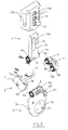
- the seatings provided in the sleeves 4 and 5 form part of the articulated joint 2, which also comprises two substantially U-shaped members, each of which is made up of an end element 6, 7.
- a pair of pins, respectively indicated by 8a,b and 9a,b, extends from end elements 6, 7, each of them being engaged with the seatings of the sleeves 4 and 5 from opposite sides, thus forming an articulated joint with two hinges having parallel axes.
- Frontally toothed gears 6a, b and 7a, b are arranged at the base of pins 8a, b and 9a, b in a coaxial relation with them.
- Gears 6a, b and 7a, b are designed to engage with corresponding frontally toothed gears 4a and 5a at the ends of the sleeve seatings 4 and 5.
- a stem 10 extends from one of the two end elements 6 or 7 and is formed with a threaded end capable of engaging with a corresponding seating, not shown, provided on a locking nut 11 pivotally connected to the other end element 6 or 7 of the articulated joint 2.
- Stem 10 is parallel to the axes of the sleeve seatings 4 and 5 and extends between them.
- locking nut 11 By rotating locking nut 11, it is possible to screw it onto the stem 10, thus making it function as a tie rod that will gradually bring the substantially U-shaped members closer to each other and thus also bring the frontally toothed gears 4a and 5a, formed at the ends of the sleeve seatings 4 and 5, closer to the corresponding frontally toothed gears 6a,b and 7a,b, until they eventually engage with each other and completely lock the articulated joint.
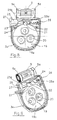
- connection plate 3 it is thus possible to choose the preferred angular orientation for the connection plate 3, and therefore also of the plane in which the holster lies, around the axis of the seatings of the sleeve 5, as well as the preferred angular orientation of the sleeve seatings 5 with respect to the sleeve seating 4, thereby displacing the planes of loop attachment 1 and connection plate 3 with respect to each other.
- the articulated joint 2 can be locked by simply rotating the locking nut 11 as described above.
- the loop attachment 1 comprises a box-shaped body 12 with belt passages 13a and 13b formed along two sides.
- the interior of the box-shaped body 12 defines a seat 14 for a bracket 15 extending radially from the sleeve 4 and slidingly housed within seat 14.
- a flexible tongue 16 is cut from the bracket and is so shaped as to be slightly inclined with respect to the plane of the bracket 15.
- On one face of the box-like body 12 there are provided some axially aligned openings, (three openings and of circular shape in the present embodiment of the invention), while the free end of the tongue 16 has an enlargement 16a of such shape as to snap into a reversible engagement with one of the openings 17, though partially projecting from it.
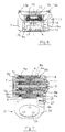
- connection plate 3 to which the holster is attached is actually formed by two shells 3a and 3b fixable to each other by means of screws 18 to clasp between them the externally projecting edge 19a of a disc-shaped body 19 provided with means for the holster connection (in this specific case through holes 20 for a screw connection).
- a cavity 21 engaging with a small cylinder 22 perpendicular to the shells 3a, 3b and integrally attached to them, though it can slide in the radial direction of the disc-shaped body 19.
- a seating 23 is formed on the inner face of the shell 3a, said seating being delimited by a U-shaped wall 24 within which one end of the small cylinder 22 is arranged.
- the small cylinder 22 is prevented from sliding in the seating 23 by an arm 25 that rests elastically against it.
- the arm 25 extends slidingly between the two shells 3a and 3b and in parallel with the sleeve 5 between the sleeve and the disc-shaped body 19.
- An edge portion 25a of arm 25 is shaped and made concave enough to bear against the small cylinder 22 and thus prevent it from sliding.
- a spring 26 is arranged between the free end of the arm 25 and the edge of the shell 3a to keep the concave portion 25a elastically forced against the small cylinder 22.
- a further and more concave portion 25b is formed adjacent to the concave portion 25a along with the edge of arm 25 in such a way as not to abut against the cylinder 22, which is therefore free to slide.
- the adjustable holster securement device allows all the previously recalled drawbacks associated with holster securement devices of the conventional type to be avoided.
- the fact that the system for regulating the height of the holster securement device is incorporated in the loop attachment not only allows for a significant reduction of the encumbrance of the connection plate 3, but also offers the possibility of minimizing the number of components of the holster securement device that remain attached to the belt in all the conditions in which it is not necessary for the user to carry the weapon with him.
- the bracket 15 can be completely withdrawn from the box-shaped body 12, so that the latter only remains attached to the belt in all these cases.
Landscapes
- Engineering & Computer Science (AREA)
- General Engineering & Computer Science (AREA)
- Casings For Electric Apparatus (AREA)
- Invalid Beds And Related Equipment (AREA)
- Electrical Discharge Machining, Electrochemical Machining, And Combined Machining (AREA)
- Forklifts And Lifting Vehicles (AREA)
- Toys (AREA)
- Prostheses (AREA)
Applications Claiming Priority (2)
| Application Number | Priority Date | Filing Date | Title |
|---|---|---|---|
| IT000145A ITFI20030145A1 (it) | 2003-05-23 | 2003-05-23 | Portafondina regolabile perfezionato. |
| ITFI20030145 | 2003-05-23 |
Publications (3)
| Publication Number | Publication Date |
|---|---|
| EP1479998A2 true EP1479998A2 (de) | 2004-11-24 |
| EP1479998A3 EP1479998A3 (de) | 2007-08-15 |
| EP1479998B1 EP1479998B1 (de) | 2011-02-16 |
Family
ID=33042690
Family Applications (1)
| Application Number | Title | Priority Date | Filing Date |
|---|---|---|---|
| EP04425353A Expired - Lifetime EP1479998B1 (de) | 2003-05-23 | 2004-05-18 | Verstellbare Halterung für ein Halfter |
Country Status (6)
| Country | Link |
|---|---|
| US (1) | US7690541B2 (de) |
| EP (1) | EP1479998B1 (de) |
| AT (1) | ATE498815T1 (de) |
| DE (1) | DE602004031394D1 (de) |
| ES (1) | ES2359976T3 (de) |
| IT (1) | ITFI20030145A1 (de) |
Cited By (8)
| Publication number | Priority date | Publication date | Assignee | Title |
|---|---|---|---|---|
| DE212008000079U1 (de) | 2007-10-30 | 2010-09-23 | Land NRW - vertreten durch das Innenministerium NRW, dieses vertreten durch das Landesamt für Zentrale Polizeiliche Dienste NRW, dieses vertreten durch den Direktor | Waffenholster mit verstellbarem Ziehwinkel insbesondere für Faustfeuerwaffen sowie Rastgelenkeinheit insbesondere für Waffenholster |
| WO2011087907A1 (en) | 2010-01-13 | 2011-07-21 | Gregory Thomas M | Multi-disk accessory attachment platform |
| WO2012143882A1 (en) | 2011-04-20 | 2012-10-26 | Radar Leather Division S.R.L. | A holster support |
| JP2013018064A (ja) * | 2011-07-08 | 2013-01-31 | Saburo Hayashi | 接続ドリル用ケース |
| EP3553456A1 (de) * | 2018-04-11 | 2019-10-16 | Safariland, LLC | Halfterträger |
| WO2020104717A1 (es) | 2018-11-21 | 2020-05-28 | Garcia Ruiz Jorge | Sistema de pistolera, soporte, funda y anclaje de armas de liberación rápida |
| US10782094B2 (en) | 2018-01-18 | 2020-09-22 | Safariland, Llc | Holster mount with adjustable drop and cant |
| US10883795B2 (en) | 2018-01-18 | 2021-01-05 | Safariland, Llc | Holster mount with adjustable drop and cant |
Families Citing this family (19)
| Publication number | Priority date | Publication date | Assignee | Title |
|---|---|---|---|---|
| USD508318S1 (en) * | 2004-07-07 | 2005-08-16 | Blackhawk Industries Product Group Unlimited Llc | Holster holder device |
| USD507104S1 (en) * | 2004-07-07 | 2005-07-12 | Blackhawk Industries Product Group Unlimted Llc | Holster holder device |
| US9271561B2 (en) * | 2013-02-08 | 2016-03-01 | David Chang | Apparatus for improving the interchangeability of portable electronic devices amongst various supports and related methods |
| US9408456B2 (en) * | 2013-06-27 | 2016-08-09 | John Kenison Hart | Universal mobile device holder |
| US9797679B2 (en) * | 2014-02-18 | 2017-10-24 | Wild Bucks Outdoors, LLC | Hands-free support device, a subassembly of a hands-free support device and methods for operating the same |
| US9835410B2 (en) | 2014-07-23 | 2017-12-05 | Blue Line Tactical, Llc | Rotatable holster |
| US20180010885A1 (en) * | 2016-07-07 | 2018-01-11 | Tedder Industries, LLC | Adjustable Clip |
| CN106500544A (zh) * | 2017-01-05 | 2017-03-15 | 张勇 | 一种具有方便插拔及防盗抢的保护机构的枪套 |
| US10575625B2 (en) * | 2017-07-24 | 2020-03-03 | Kevin Senn | Systems and methods associated with a container holder |
| AU2019237543B2 (en) | 2018-03-23 | 2024-09-26 | Revelyst Operations Llc | Thumb-actuated locking holster |
| US10996024B2 (en) | 2018-03-23 | 2021-05-04 | Vista Outdoor Operations Llc | Thumb-actuated locking holster |
| US10883796B2 (en) * | 2018-07-13 | 2021-01-05 | Edge-Works Manufacturing Company | Adjustable position magazine carrier |
| CN116551640A (zh) | 2019-02-12 | 2023-08-08 | 米沃奇电动工具公司 | 工具附接系统 |
| US11666135B2 (en) * | 2019-07-01 | 2023-06-06 | Randy Dellwo | Smartphone holster |
| US11143487B1 (en) | 2020-03-24 | 2021-10-12 | John Alexander Reich | Multiple-position firearm holster adapter and system |
| US11781831B2 (en) * | 2020-06-12 | 2023-10-10 | Vista Outdoor Operations Llc | Thumb-actuated locking holster system |
| US11397069B2 (en) | 2020-12-04 | 2022-07-26 | Vista Outdoor Operations Llc | Locking holster system |
| JP2025527809A (ja) * | 2022-08-29 | 2025-08-22 | ボーモント-ジョーンズ ジェイムズ | コンパクトな竿保持具 |
| US20240361100A1 (en) * | 2023-04-25 | 2024-10-31 | Henning's Shop, LLC | Multi-directional adjustable holster hanger |
Family Cites Families (6)
| Publication number | Priority date | Publication date | Assignee | Title |
|---|---|---|---|---|
| US3589574A (en) * | 1969-06-30 | 1971-06-29 | Fred R Marburger | Adjustable belt loop assembly for pistol holsters and the like |
| US5421497A (en) * | 1993-08-26 | 1995-06-06 | Gilmore; W. Riley | Variable position handgun holster |
| DE9313311U1 (de) * | 1993-09-04 | 1993-11-18 | Nowar security equipment GmbH, 51674 Wiehl | Pendelstegholster |
| US6161741A (en) * | 1999-06-14 | 2000-12-19 | Michaels Of Oregon Co. | Holster securement system |
| ITFI20010090A1 (it) * | 2001-05-16 | 2002-11-16 | Gargani Elsa | Passante portafondina ad inclinazione regolabile e con sistema di aggancio-sgancio rapido della fondina |
| ITPI20010082A1 (it) * | 2001-12-05 | 2002-03-05 | Alfonso Leto | Dispositivo regolabile per l'applicazione della fondina della pistolaalla cintura dell'operatore. |
-
2003
- 2003-05-23 IT IT000145A patent/ITFI20030145A1/it unknown
-
2004
- 2004-05-18 DE DE602004031394T patent/DE602004031394D1/de not_active Expired - Lifetime
- 2004-05-18 ES ES04425353T patent/ES2359976T3/es not_active Expired - Lifetime
- 2004-05-18 AT AT04425353T patent/ATE498815T1/de not_active IP Right Cessation
- 2004-05-18 EP EP04425353A patent/EP1479998B1/de not_active Expired - Lifetime
- 2004-05-23 US US10/852,332 patent/US7690541B2/en active Active
Cited By (10)
| Publication number | Priority date | Publication date | Assignee | Title |
|---|---|---|---|---|
| DE212008000079U1 (de) | 2007-10-30 | 2010-09-23 | Land NRW - vertreten durch das Innenministerium NRW, dieses vertreten durch das Landesamt für Zentrale Polizeiliche Dienste NRW, dieses vertreten durch den Direktor | Waffenholster mit verstellbarem Ziehwinkel insbesondere für Faustfeuerwaffen sowie Rastgelenkeinheit insbesondere für Waffenholster |
| WO2011087907A1 (en) | 2010-01-13 | 2011-07-21 | Gregory Thomas M | Multi-disk accessory attachment platform |
| EP2524188A4 (de) * | 2010-01-13 | 2015-04-08 | Alliant Techsystems Inc | Plattform zur befestigung eines aus mehreren scheiben bestehenden zubehörs |
| WO2012143882A1 (en) | 2011-04-20 | 2012-10-26 | Radar Leather Division S.R.L. | A holster support |
| JP2013018064A (ja) * | 2011-07-08 | 2013-01-31 | Saburo Hayashi | 接続ドリル用ケース |
| US10782094B2 (en) | 2018-01-18 | 2020-09-22 | Safariland, Llc | Holster mount with adjustable drop and cant |
| US10883795B2 (en) | 2018-01-18 | 2021-01-05 | Safariland, Llc | Holster mount with adjustable drop and cant |
| EP3553456A1 (de) * | 2018-04-11 | 2019-10-16 | Safariland, LLC | Halfterträger |
| WO2020104717A1 (es) | 2018-11-21 | 2020-05-28 | Garcia Ruiz Jorge | Sistema de pistolera, soporte, funda y anclaje de armas de liberación rápida |
| US11725906B2 (en) | 2018-11-21 | 2023-08-15 | Jorge Garcia Ruiz | Holster system, holder, holster and quick-release gun anchor system |
Also Published As
| Publication number | Publication date |
|---|---|
| US7690541B2 (en) | 2010-04-06 |
| EP1479998B1 (de) | 2011-02-16 |
| ATE498815T1 (de) | 2011-03-15 |
| DE602004031394D1 (de) | 2011-03-31 |
| ITFI20030145A1 (it) | 2004-11-24 |
| US20040251284A1 (en) | 2004-12-16 |
| ES2359976T3 (es) | 2011-05-30 |
| EP1479998A3 (de) | 2007-08-15 |
Similar Documents
| Publication | Publication Date | Title |
|---|---|---|
| EP1479998B1 (de) | Verstellbare Halterung für ein Halfter | |
| US6431025B1 (en) | Ratchet mechanism for a surgical retractor assembly | |
| US5988577A (en) | Adjustable carrier assembly for a wireless communication device | |
| US5956776A (en) | Adjustable helmet having an improved locking mechanism | |
| US5292303A (en) | Hinged orthopedic brace having an adjustable pivot range | |
| US4512051A (en) | Handtool | |
| US7083583B2 (en) | Orthesis comprising an adjustable range of movement | |
| EP2348906B1 (de) | Stirnband mit drehkissen | |
| US7966760B2 (en) | Modular gunstock | |
| US7975318B2 (en) | Head strap | |
| EP3420295B1 (de) | Einstellvorrichtung für eine verstellbare stütze für einen gewehrschaft | |
| US6039709A (en) | Orthopedic hinge assembly | |
| US6010045A (en) | Adjustable carrier | |
| US6745480B1 (en) | Saw having an angle adjustable blade | |
| US9889036B2 (en) | Joint orthosis | |
| US20190084817A1 (en) | Pivoting prybar head | |
| US6957866B1 (en) | Adjustable armrest assembly for chair | |
| US20240175659A1 (en) | Adjustable,interchangeable holster | |
| US20240115032A1 (en) | Adjustable mount for a backpack or schoolbag | |
| US5454380A (en) | Ergonomic hand support for use during a work operation to prevent the risk of adverse medical conditions, such as carpal tunnel syndrome | |
| EP0832624B1 (de) | Gelenk mit Mitteln zur Begrenzung der Bewegung | |
| CA2572905A1 (en) | Lock | |
| US6500139B1 (en) | Orthopedic knee brace joint assembly having a trigger locking mechanism | |
| EP1717137A1 (de) | Bewegliches Gestell für ein Motorrad | |
| JP2911119B1 (ja) | 南京錠の製造方法 |
Legal Events
| Date | Code | Title | Description |
|---|---|---|---|
| PUAI | Public reference made under article 153(3) epc to a published international application that has entered the european phase |
Free format text: ORIGINAL CODE: 0009012 |
|
| AK | Designated contracting states |
Kind code of ref document: A2 Designated state(s): AT BE BG CH CY CZ DE DK EE ES FI FR GB GR HU IE IT LI LU MC NL PL PT RO SE SI SK TR |
|
| AX | Request for extension of the european patent |
Extension state: AL HR LT LV MK |
|
| PUAL | Search report despatched |
Free format text: ORIGINAL CODE: 0009013 |
|
| AK | Designated contracting states |
Kind code of ref document: A3 Designated state(s): AT BE BG CH CY CZ DE DK EE ES FI FR GB GR HU IE IT LI LU MC NL PL PT RO SE SI SK TR |
|
| AX | Request for extension of the european patent |
Extension state: AL HR LT LV MK |
|
| AKX | Designation fees paid | ||
| REG | Reference to a national code |
Ref country code: DE Ref legal event code: 8566 |
|
| RBV | Designated contracting states (corrected) |
Designated state(s): AT BE BG CH CY CZ DE DK EE ES FI FR GB GR HU IE IT LI LU MC NL PL PT RO SE SI SK TR |
|
| 17P | Request for examination filed |
Effective date: 20080528 |
|
| 17Q | First examination report despatched |
Effective date: 20080930 |
|
| GRAP | Despatch of communication of intention to grant a patent |
Free format text: ORIGINAL CODE: EPIDOSNIGR1 |
|
| RIC1 | Information provided on ipc code assigned before grant |
Ipc: F41C 33/04 20060101AFI20100628BHEP |
|
| GRAS | Grant fee paid |
Free format text: ORIGINAL CODE: EPIDOSNIGR3 |
|
| GRAA | (expected) grant |
Free format text: ORIGINAL CODE: 0009210 |
|
| AK | Designated contracting states |
Kind code of ref document: B1 Designated state(s): AT BE BG CH CY CZ DE DK EE ES FI FR GB GR HU IE IT LI LU MC NL PL PT RO SE SI SK TR |
|
| REG | Reference to a national code |
Ref country code: GB Ref legal event code: FG4D |
|
| REG | Reference to a national code |
Ref country code: CH Ref legal event code: EP |
|
| REG | Reference to a national code |
Ref country code: IE Ref legal event code: FG4D |
|
| REF | Corresponds to: |
Ref document number: 602004031394 Country of ref document: DE Date of ref document: 20110331 Kind code of ref document: P |
|
| REG | Reference to a national code |
Ref country code: DE Ref legal event code: R096 Ref document number: 602004031394 Country of ref document: DE Effective date: 20110331 |
|
| REG | Reference to a national code |
Ref country code: ES Ref legal event code: FG2A Ref document number: 2359976 Country of ref document: ES Kind code of ref document: T3 Effective date: 20110530 |
|
| REG | Reference to a national code |
Ref country code: NL Ref legal event code: VDEP Effective date: 20110216 |
|
| PG25 | Lapsed in a contracting state [announced via postgrant information from national office to epo] |
Ref country code: PT Free format text: LAPSE BECAUSE OF FAILURE TO SUBMIT A TRANSLATION OF THE DESCRIPTION OR TO PAY THE FEE WITHIN THE PRESCRIBED TIME-LIMIT Effective date: 20110616 Ref country code: GR Free format text: LAPSE BECAUSE OF FAILURE TO SUBMIT A TRANSLATION OF THE DESCRIPTION OR TO PAY THE FEE WITHIN THE PRESCRIBED TIME-LIMIT Effective date: 20110517 Ref country code: SE Free format text: LAPSE BECAUSE OF FAILURE TO SUBMIT A TRANSLATION OF THE DESCRIPTION OR TO PAY THE FEE WITHIN THE PRESCRIBED TIME-LIMIT Effective date: 20110216 |
|
| PG25 | Lapsed in a contracting state [announced via postgrant information from national office to epo] |
Ref country code: BE Free format text: LAPSE BECAUSE OF FAILURE TO SUBMIT A TRANSLATION OF THE DESCRIPTION OR TO PAY THE FEE WITHIN THE PRESCRIBED TIME-LIMIT Effective date: 20110216 Ref country code: BG Free format text: LAPSE BECAUSE OF FAILURE TO SUBMIT A TRANSLATION OF THE DESCRIPTION OR TO PAY THE FEE WITHIN THE PRESCRIBED TIME-LIMIT Effective date: 20110516 Ref country code: NL Free format text: LAPSE BECAUSE OF FAILURE TO SUBMIT A TRANSLATION OF THE DESCRIPTION OR TO PAY THE FEE WITHIN THE PRESCRIBED TIME-LIMIT Effective date: 20110216 Ref country code: FI Free format text: LAPSE BECAUSE OF FAILURE TO SUBMIT A TRANSLATION OF THE DESCRIPTION OR TO PAY THE FEE WITHIN THE PRESCRIBED TIME-LIMIT Effective date: 20110216 Ref country code: CY Free format text: LAPSE BECAUSE OF FAILURE TO SUBMIT A TRANSLATION OF THE DESCRIPTION OR TO PAY THE FEE WITHIN THE PRESCRIBED TIME-LIMIT Effective date: 20110216 Ref country code: SI Free format text: LAPSE BECAUSE OF FAILURE TO SUBMIT A TRANSLATION OF THE DESCRIPTION OR TO PAY THE FEE WITHIN THE PRESCRIBED TIME-LIMIT Effective date: 20110216 Ref country code: AT Free format text: LAPSE BECAUSE OF FAILURE TO SUBMIT A TRANSLATION OF THE DESCRIPTION OR TO PAY THE FEE WITHIN THE PRESCRIBED TIME-LIMIT Effective date: 20110216 Ref country code: PL Free format text: LAPSE BECAUSE OF FAILURE TO SUBMIT A TRANSLATION OF THE DESCRIPTION OR TO PAY THE FEE WITHIN THE PRESCRIBED TIME-LIMIT Effective date: 20110216 |
|
| PG25 | Lapsed in a contracting state [announced via postgrant information from national office to epo] |
Ref country code: EE Free format text: LAPSE BECAUSE OF FAILURE TO SUBMIT A TRANSLATION OF THE DESCRIPTION OR TO PAY THE FEE WITHIN THE PRESCRIBED TIME-LIMIT Effective date: 20110216 Ref country code: DK Free format text: LAPSE BECAUSE OF FAILURE TO SUBMIT A TRANSLATION OF THE DESCRIPTION OR TO PAY THE FEE WITHIN THE PRESCRIBED TIME-LIMIT Effective date: 20110216 |
|
| PG25 | Lapsed in a contracting state [announced via postgrant information from national office to epo] |
Ref country code: SK Free format text: LAPSE BECAUSE OF FAILURE TO SUBMIT A TRANSLATION OF THE DESCRIPTION OR TO PAY THE FEE WITHIN THE PRESCRIBED TIME-LIMIT Effective date: 20110216 Ref country code: CZ Free format text: LAPSE BECAUSE OF FAILURE TO SUBMIT A TRANSLATION OF THE DESCRIPTION OR TO PAY THE FEE WITHIN THE PRESCRIBED TIME-LIMIT Effective date: 20110216 Ref country code: RO Free format text: LAPSE BECAUSE OF FAILURE TO SUBMIT A TRANSLATION OF THE DESCRIPTION OR TO PAY THE FEE WITHIN THE PRESCRIBED TIME-LIMIT Effective date: 20110216 |
|
| PLBE | No opposition filed within time limit |
Free format text: ORIGINAL CODE: 0009261 |
|
| STAA | Information on the status of an ep patent application or granted ep patent |
Free format text: STATUS: NO OPPOSITION FILED WITHIN TIME LIMIT |
|
| PG25 | Lapsed in a contracting state [announced via postgrant information from national office to epo] |
Ref country code: MC Free format text: LAPSE BECAUSE OF NON-PAYMENT OF DUE FEES Effective date: 20110531 |
|
| REG | Reference to a national code |
Ref country code: CH Ref legal event code: PL |
|
| 26N | No opposition filed |
Effective date: 20111117 |
|
| PG25 | Lapsed in a contracting state [announced via postgrant information from national office to epo] |
Ref country code: LI Free format text: LAPSE BECAUSE OF NON-PAYMENT OF DUE FEES Effective date: 20110531 Ref country code: CH Free format text: LAPSE BECAUSE OF NON-PAYMENT OF DUE FEES Effective date: 20110531 |
|
| REG | Reference to a national code |
Ref country code: IE Ref legal event code: MM4A |
|
| REG | Reference to a national code |
Ref country code: DE Ref legal event code: R097 Ref document number: 602004031394 Country of ref document: DE Effective date: 20111117 |
|
| PG25 | Lapsed in a contracting state [announced via postgrant information from national office to epo] |
Ref country code: IE Free format text: LAPSE BECAUSE OF NON-PAYMENT OF DUE FEES Effective date: 20110518 |
|
| PG25 | Lapsed in a contracting state [announced via postgrant information from national office to epo] |
Ref country code: IT Free format text: LAPSE BECAUSE OF FAILURE TO SUBMIT A TRANSLATION OF THE DESCRIPTION OR TO PAY THE FEE WITHIN THE PRESCRIBED TIME-LIMIT Effective date: 20110216 |
|
| PG25 | Lapsed in a contracting state [announced via postgrant information from national office to epo] |
Ref country code: LU Free format text: LAPSE BECAUSE OF NON-PAYMENT OF DUE FEES Effective date: 20110518 |
|
| PG25 | Lapsed in a contracting state [announced via postgrant information from national office to epo] |
Ref country code: TR Free format text: LAPSE BECAUSE OF FAILURE TO SUBMIT A TRANSLATION OF THE DESCRIPTION OR TO PAY THE FEE WITHIN THE PRESCRIBED TIME-LIMIT Effective date: 20110216 |
|
| PG25 | Lapsed in a contracting state [announced via postgrant information from national office to epo] |
Ref country code: HU Free format text: LAPSE BECAUSE OF FAILURE TO SUBMIT A TRANSLATION OF THE DESCRIPTION OR TO PAY THE FEE WITHIN THE PRESCRIBED TIME-LIMIT Effective date: 20110216 |
|
| REG | Reference to a national code |
Ref country code: FR Ref legal event code: PLFP Year of fee payment: 12 |
|
| PGFP | Annual fee paid to national office [announced via postgrant information from national office to epo] |
Ref country code: ES Payment date: 20150527 Year of fee payment: 12 Ref country code: GB Payment date: 20150521 Year of fee payment: 12 |
|
| PGFP | Annual fee paid to national office [announced via postgrant information from national office to epo] |
Ref country code: FR Payment date: 20150521 Year of fee payment: 12 |
|
| GBPC | Gb: european patent ceased through non-payment of renewal fee |
Effective date: 20160518 |
|
| REG | Reference to a national code |
Ref country code: FR Ref legal event code: ST Effective date: 20170131 |
|
| PG25 | Lapsed in a contracting state [announced via postgrant information from national office to epo] |
Ref country code: FR Free format text: LAPSE BECAUSE OF NON-PAYMENT OF DUE FEES Effective date: 20160531 |
|
| PG25 | Lapsed in a contracting state [announced via postgrant information from national office to epo] |
Ref country code: GB Free format text: LAPSE BECAUSE OF NON-PAYMENT OF DUE FEES Effective date: 20160518 |
|
| PG25 | Lapsed in a contracting state [announced via postgrant information from national office to epo] |
Ref country code: ES Free format text: LAPSE BECAUSE OF NON-PAYMENT OF DUE FEES Effective date: 20160519 |
|
| REG | Reference to a national code |
Ref country code: ES Ref legal event code: FD2A Effective date: 20180626 |
|
| PGFP | Annual fee paid to national office [announced via postgrant information from national office to epo] |
Ref country code: DE Payment date: 20220620 Year of fee payment: 20 |
|
| REG | Reference to a national code |
Ref country code: DE Ref legal event code: R071 Ref document number: 602004031394 Country of ref document: DE |