EP1479884A2 - An exhaust system and process for operating the same - Google Patents
An exhaust system and process for operating the same Download PDFInfo
- Publication number
- EP1479884A2 EP1479884A2 EP04076356A EP04076356A EP1479884A2 EP 1479884 A2 EP1479884 A2 EP 1479884A2 EP 04076356 A EP04076356 A EP 04076356A EP 04076356 A EP04076356 A EP 04076356A EP 1479884 A2 EP1479884 A2 EP 1479884A2
- Authority
- EP
- European Patent Office
- Prior art keywords
- exhaust
- conduit
- exhaust gas
- operating
- flow
- Prior art date
- Legal status (The legal status is an assumption and is not a legal conclusion. Google has not performed a legal analysis and makes no representation as to the accuracy of the status listed.)
- Withdrawn
Links
Images




Classifications
-
- F—MECHANICAL ENGINEERING; LIGHTING; HEATING; WEAPONS; BLASTING
- F01—MACHINES OR ENGINES IN GENERAL; ENGINE PLANTS IN GENERAL; STEAM ENGINES
- F01N—GAS-FLOW SILENCERS OR EXHAUST APPARATUS FOR MACHINES OR ENGINES IN GENERAL; GAS-FLOW SILENCERS OR EXHAUST APPARATUS FOR INTERNAL-COMBUSTION ENGINES
- F01N3/00—Exhaust or silencing apparatus having means for purifying, rendering innocuous, or otherwise treating exhaust
- F01N3/08—Exhaust or silencing apparatus having means for purifying, rendering innocuous, or otherwise treating exhaust for rendering innocuous
- F01N3/10—Exhaust or silencing apparatus having means for purifying, rendering innocuous, or otherwise treating exhaust for rendering innocuous by thermal or catalytic conversion of noxious components of exhaust
- F01N3/18—Exhaust or silencing apparatus having means for purifying, rendering innocuous, or otherwise treating exhaust for rendering innocuous by thermal or catalytic conversion of noxious components of exhaust characterised by methods of operation; Control
- F01N3/20—Exhaust or silencing apparatus having means for purifying, rendering innocuous, or otherwise treating exhaust for rendering innocuous by thermal or catalytic conversion of noxious components of exhaust characterised by methods of operation; Control specially adapted for catalytic conversion
- F01N3/2006—Periodically heating or cooling catalytic reactors, e.g. at cold starting or overheating
-
- F—MECHANICAL ENGINEERING; LIGHTING; HEATING; WEAPONS; BLASTING
- F01—MACHINES OR ENGINES IN GENERAL; ENGINE PLANTS IN GENERAL; STEAM ENGINES
- F01N—GAS-FLOW SILENCERS OR EXHAUST APPARATUS FOR MACHINES OR ENGINES IN GENERAL; GAS-FLOW SILENCERS OR EXHAUST APPARATUS FOR INTERNAL-COMBUSTION ENGINES
- F01N13/00—Exhaust or silencing apparatus characterised by constructional features
- F01N13/009—Exhaust or silencing apparatus characterised by constructional features having two or more separate purifying devices arranged in series
-
- F—MECHANICAL ENGINEERING; LIGHTING; HEATING; WEAPONS; BLASTING
- F01—MACHINES OR ENGINES IN GENERAL; ENGINE PLANTS IN GENERAL; STEAM ENGINES
- F01N—GAS-FLOW SILENCERS OR EXHAUST APPARATUS FOR MACHINES OR ENGINES IN GENERAL; GAS-FLOW SILENCERS OR EXHAUST APPARATUS FOR INTERNAL-COMBUSTION ENGINES
- F01N13/00—Exhaust or silencing apparatus characterised by constructional features
- F01N13/011—Exhaust or silencing apparatus characterised by constructional features having two or more purifying devices arranged in parallel
-
- F—MECHANICAL ENGINEERING; LIGHTING; HEATING; WEAPONS; BLASTING
- F01—MACHINES OR ENGINES IN GENERAL; ENGINE PLANTS IN GENERAL; STEAM ENGINES
- F01N—GAS-FLOW SILENCERS OR EXHAUST APPARATUS FOR MACHINES OR ENGINES IN GENERAL; GAS-FLOW SILENCERS OR EXHAUST APPARATUS FOR INTERNAL-COMBUSTION ENGINES
- F01N13/00—Exhaust or silencing apparatus characterised by constructional features
- F01N13/011—Exhaust or silencing apparatus characterised by constructional features having two or more purifying devices arranged in parallel
- F01N13/017—Exhaust or silencing apparatus characterised by constructional features having two or more purifying devices arranged in parallel the purifying devices are arranged in a single housing
-
- F—MECHANICAL ENGINEERING; LIGHTING; HEATING; WEAPONS; BLASTING
- F01—MACHINES OR ENGINES IN GENERAL; ENGINE PLANTS IN GENERAL; STEAM ENGINES
- F01N—GAS-FLOW SILENCERS OR EXHAUST APPARATUS FOR MACHINES OR ENGINES IN GENERAL; GAS-FLOW SILENCERS OR EXHAUST APPARATUS FOR INTERNAL-COMBUSTION ENGINES
- F01N3/00—Exhaust or silencing apparatus having means for purifying, rendering innocuous, or otherwise treating exhaust
- F01N3/02—Exhaust or silencing apparatus having means for purifying, rendering innocuous, or otherwise treating exhaust for cooling, or for removing solid constituents of, exhaust
- F01N3/021—Exhaust or silencing apparatus having means for purifying, rendering innocuous, or otherwise treating exhaust for cooling, or for removing solid constituents of, exhaust by means of filters
- F01N3/023—Exhaust or silencing apparatus having means for purifying, rendering innocuous, or otherwise treating exhaust for cooling, or for removing solid constituents of, exhaust by means of filters using means for regenerating the filters, e.g. by burning trapped particles
-
- F—MECHANICAL ENGINEERING; LIGHTING; HEATING; WEAPONS; BLASTING
- F01—MACHINES OR ENGINES IN GENERAL; ENGINE PLANTS IN GENERAL; STEAM ENGINES
- F01N—GAS-FLOW SILENCERS OR EXHAUST APPARATUS FOR MACHINES OR ENGINES IN GENERAL; GAS-FLOW SILENCERS OR EXHAUST APPARATUS FOR INTERNAL-COMBUSTION ENGINES
- F01N3/00—Exhaust or silencing apparatus having means for purifying, rendering innocuous, or otherwise treating exhaust
- F01N3/02—Exhaust or silencing apparatus having means for purifying, rendering innocuous, or otherwise treating exhaust for cooling, or for removing solid constituents of, exhaust
- F01N3/021—Exhaust or silencing apparatus having means for purifying, rendering innocuous, or otherwise treating exhaust for cooling, or for removing solid constituents of, exhaust by means of filters
- F01N3/023—Exhaust or silencing apparatus having means for purifying, rendering innocuous, or otherwise treating exhaust for cooling, or for removing solid constituents of, exhaust by means of filters using means for regenerating the filters, e.g. by burning trapped particles
- F01N3/0235—Exhaust or silencing apparatus having means for purifying, rendering innocuous, or otherwise treating exhaust for cooling, or for removing solid constituents of, exhaust by means of filters using means for regenerating the filters, e.g. by burning trapped particles using exhaust gas throttling means
-
- F—MECHANICAL ENGINEERING; LIGHTING; HEATING; WEAPONS; BLASTING
- F01—MACHINES OR ENGINES IN GENERAL; ENGINE PLANTS IN GENERAL; STEAM ENGINES
- F01N—GAS-FLOW SILENCERS OR EXHAUST APPARATUS FOR MACHINES OR ENGINES IN GENERAL; GAS-FLOW SILENCERS OR EXHAUST APPARATUS FOR INTERNAL-COMBUSTION ENGINES
- F01N3/00—Exhaust or silencing apparatus having means for purifying, rendering innocuous, or otherwise treating exhaust
- F01N3/02—Exhaust or silencing apparatus having means for purifying, rendering innocuous, or otherwise treating exhaust for cooling, or for removing solid constituents of, exhaust
- F01N3/021—Exhaust or silencing apparatus having means for purifying, rendering innocuous, or otherwise treating exhaust for cooling, or for removing solid constituents of, exhaust by means of filters
- F01N3/031—Exhaust or silencing apparatus having means for purifying, rendering innocuous, or otherwise treating exhaust for cooling, or for removing solid constituents of, exhaust by means of filters having means for by-passing filters, e.g. when clogged or during cold engine start
-
- F—MECHANICAL ENGINEERING; LIGHTING; HEATING; WEAPONS; BLASTING
- F01—MACHINES OR ENGINES IN GENERAL; ENGINE PLANTS IN GENERAL; STEAM ENGINES
- F01N—GAS-FLOW SILENCERS OR EXHAUST APPARATUS FOR MACHINES OR ENGINES IN GENERAL; GAS-FLOW SILENCERS OR EXHAUST APPARATUS FOR INTERNAL-COMBUSTION ENGINES
- F01N3/00—Exhaust or silencing apparatus having means for purifying, rendering innocuous, or otherwise treating exhaust
- F01N3/08—Exhaust or silencing apparatus having means for purifying, rendering innocuous, or otherwise treating exhaust for rendering innocuous
- F01N3/0807—Exhaust or silencing apparatus having means for purifying, rendering innocuous, or otherwise treating exhaust for rendering innocuous by using absorbents or adsorbents
- F01N3/0871—Exhaust or silencing apparatus having means for purifying, rendering innocuous, or otherwise treating exhaust for rendering innocuous by using absorbents or adsorbents using means for controlling, e.g. purging, the absorbents or adsorbents
-
- F—MECHANICAL ENGINEERING; LIGHTING; HEATING; WEAPONS; BLASTING
- F01—MACHINES OR ENGINES IN GENERAL; ENGINE PLANTS IN GENERAL; STEAM ENGINES
- F01N—GAS-FLOW SILENCERS OR EXHAUST APPARATUS FOR MACHINES OR ENGINES IN GENERAL; GAS-FLOW SILENCERS OR EXHAUST APPARATUS FOR INTERNAL-COMBUSTION ENGINES
- F01N3/00—Exhaust or silencing apparatus having means for purifying, rendering innocuous, or otherwise treating exhaust
- F01N3/08—Exhaust or silencing apparatus having means for purifying, rendering innocuous, or otherwise treating exhaust for rendering innocuous
- F01N3/0807—Exhaust or silencing apparatus having means for purifying, rendering innocuous, or otherwise treating exhaust for rendering innocuous by using absorbents or adsorbents
- F01N3/0871—Exhaust or silencing apparatus having means for purifying, rendering innocuous, or otherwise treating exhaust for rendering innocuous by using absorbents or adsorbents using means for controlling, e.g. purging, the absorbents or adsorbents
- F01N3/0878—Bypassing absorbents or adsorbents
-
- F—MECHANICAL ENGINEERING; LIGHTING; HEATING; WEAPONS; BLASTING
- F01—MACHINES OR ENGINES IN GENERAL; ENGINE PLANTS IN GENERAL; STEAM ENGINES
- F01N—GAS-FLOW SILENCERS OR EXHAUST APPARATUS FOR MACHINES OR ENGINES IN GENERAL; GAS-FLOW SILENCERS OR EXHAUST APPARATUS FOR INTERNAL-COMBUSTION ENGINES
- F01N3/00—Exhaust or silencing apparatus having means for purifying, rendering innocuous, or otherwise treating exhaust
- F01N3/08—Exhaust or silencing apparatus having means for purifying, rendering innocuous, or otherwise treating exhaust for rendering innocuous
- F01N3/0807—Exhaust or silencing apparatus having means for purifying, rendering innocuous, or otherwise treating exhaust for rendering innocuous by using absorbents or adsorbents
- F01N3/0871—Exhaust or silencing apparatus having means for purifying, rendering innocuous, or otherwise treating exhaust for rendering innocuous by using absorbents or adsorbents using means for controlling, e.g. purging, the absorbents or adsorbents
- F01N3/0885—Regeneration of deteriorated absorbents or adsorbents, e.g. desulfurization of NOx traps
-
- F—MECHANICAL ENGINEERING; LIGHTING; HEATING; WEAPONS; BLASTING
- F01—MACHINES OR ENGINES IN GENERAL; ENGINE PLANTS IN GENERAL; STEAM ENGINES
- F01N—GAS-FLOW SILENCERS OR EXHAUST APPARATUS FOR MACHINES OR ENGINES IN GENERAL; GAS-FLOW SILENCERS OR EXHAUST APPARATUS FOR INTERNAL-COMBUSTION ENGINES
- F01N13/00—Exhaust or silencing apparatus characterised by constructional features
- F01N13/14—Exhaust or silencing apparatus characterised by constructional features having thermal insulation
-
- F—MECHANICAL ENGINEERING; LIGHTING; HEATING; WEAPONS; BLASTING
- F01—MACHINES OR ENGINES IN GENERAL; ENGINE PLANTS IN GENERAL; STEAM ENGINES
- F01N—GAS-FLOW SILENCERS OR EXHAUST APPARATUS FOR MACHINES OR ENGINES IN GENERAL; GAS-FLOW SILENCERS OR EXHAUST APPARATUS FOR INTERNAL-COMBUSTION ENGINES
- F01N2260/00—Exhaust treating devices having provisions not otherwise provided for
- F01N2260/04—Exhaust treating devices having provisions not otherwise provided for for regeneration or reactivation, e.g. of catalyst
-
- F—MECHANICAL ENGINEERING; LIGHTING; HEATING; WEAPONS; BLASTING
- F01—MACHINES OR ENGINES IN GENERAL; ENGINE PLANTS IN GENERAL; STEAM ENGINES
- F01N—GAS-FLOW SILENCERS OR EXHAUST APPARATUS FOR MACHINES OR ENGINES IN GENERAL; GAS-FLOW SILENCERS OR EXHAUST APPARATUS FOR INTERNAL-COMBUSTION ENGINES
- F01N2260/00—Exhaust treating devices having provisions not otherwise provided for
- F01N2260/14—Exhaust treating devices having provisions not otherwise provided for for modifying or adapting flow area or back-pressure
-
- F—MECHANICAL ENGINEERING; LIGHTING; HEATING; WEAPONS; BLASTING
- F01—MACHINES OR ENGINES IN GENERAL; ENGINE PLANTS IN GENERAL; STEAM ENGINES
- F01N—GAS-FLOW SILENCERS OR EXHAUST APPARATUS FOR MACHINES OR ENGINES IN GENERAL; GAS-FLOW SILENCERS OR EXHAUST APPARATUS FOR INTERNAL-COMBUSTION ENGINES
- F01N2330/00—Structure of catalyst support or particle filter
- F01N2330/06—Ceramic, e.g. monoliths
-
- F—MECHANICAL ENGINEERING; LIGHTING; HEATING; WEAPONS; BLASTING
- F01—MACHINES OR ENGINES IN GENERAL; ENGINE PLANTS IN GENERAL; STEAM ENGINES
- F01N—GAS-FLOW SILENCERS OR EXHAUST APPARATUS FOR MACHINES OR ENGINES IN GENERAL; GAS-FLOW SILENCERS OR EXHAUST APPARATUS FOR INTERNAL-COMBUSTION ENGINES
- F01N2330/00—Structure of catalyst support or particle filter
- F01N2330/08—Granular material
-
- F—MECHANICAL ENGINEERING; LIGHTING; HEATING; WEAPONS; BLASTING
- F01—MACHINES OR ENGINES IN GENERAL; ENGINE PLANTS IN GENERAL; STEAM ENGINES
- F01N—GAS-FLOW SILENCERS OR EXHAUST APPARATUS FOR MACHINES OR ENGINES IN GENERAL; GAS-FLOW SILENCERS OR EXHAUST APPARATUS FOR INTERNAL-COMBUSTION ENGINES
- F01N2330/00—Structure of catalyst support or particle filter
- F01N2330/12—Metallic wire mesh fabric or knitting
-
- F—MECHANICAL ENGINEERING; LIGHTING; HEATING; WEAPONS; BLASTING
- F01—MACHINES OR ENGINES IN GENERAL; ENGINE PLANTS IN GENERAL; STEAM ENGINES
- F01N—GAS-FLOW SILENCERS OR EXHAUST APPARATUS FOR MACHINES OR ENGINES IN GENERAL; GAS-FLOW SILENCERS OR EXHAUST APPARATUS FOR INTERNAL-COMBUSTION ENGINES
- F01N2530/00—Selection of materials for tubes, chambers or housings
- F01N2530/02—Corrosion resistive metals
- F01N2530/04—Steel alloys, e.g. stainless steel
-
- F—MECHANICAL ENGINEERING; LIGHTING; HEATING; WEAPONS; BLASTING
- F01—MACHINES OR ENGINES IN GENERAL; ENGINE PLANTS IN GENERAL; STEAM ENGINES
- F01N—GAS-FLOW SILENCERS OR EXHAUST APPARATUS FOR MACHINES OR ENGINES IN GENERAL; GAS-FLOW SILENCERS OR EXHAUST APPARATUS FOR INTERNAL-COMBUSTION ENGINES
- F01N2570/00—Exhaust treating apparatus eliminating, absorbing or adsorbing specific elements or compounds
- F01N2570/04—Sulfur or sulfur oxides
-
- F—MECHANICAL ENGINEERING; LIGHTING; HEATING; WEAPONS; BLASTING
- F01—MACHINES OR ENGINES IN GENERAL; ENGINE PLANTS IN GENERAL; STEAM ENGINES
- F01N—GAS-FLOW SILENCERS OR EXHAUST APPARATUS FOR MACHINES OR ENGINES IN GENERAL; GAS-FLOW SILENCERS OR EXHAUST APPARATUS FOR INTERNAL-COMBUSTION ENGINES
- F01N9/00—Electrical control of exhaust gas treating apparatus
- F01N9/002—Electrical control of exhaust gas treating apparatus of filter regeneration
-
- Y—GENERAL TAGGING OF NEW TECHNOLOGICAL DEVELOPMENTS; GENERAL TAGGING OF CROSS-SECTIONAL TECHNOLOGIES SPANNING OVER SEVERAL SECTIONS OF THE IPC; TECHNICAL SUBJECTS COVERED BY FORMER USPC CROSS-REFERENCE ART COLLECTIONS [XRACs] AND DIGESTS
- Y02—TECHNOLOGIES OR APPLICATIONS FOR MITIGATION OR ADAPTATION AGAINST CLIMATE CHANGE
- Y02T—CLIMATE CHANGE MITIGATION TECHNOLOGIES RELATED TO TRANSPORTATION
- Y02T10/00—Road transport of goods or passengers
- Y02T10/10—Internal combustion engine [ICE] based vehicles
- Y02T10/12—Improving ICE efficiencies
Definitions
- Diesel particulate filters provide a diesel engine with exhaust particulate traps or filters that are operative to filter out and collect particulates from the discharged exhaust gas stream.
- a problem with diesel particulate filters is that they gradually become clogged with particulate matter contained within the exhaust gas stream, which can cause excessive backpressure, resulting in poor engine performance or damage to the engine or the filter.
- a diesel engine Under heavy loads, a diesel engine emits an exhaust gas stream at a high enough temperature to bum out the particulate matter collected by the diesel particulate filter.
- the temperature of the exhaust gas stream as it passes through the diesel particulate filter is generally below the combustion temperature of the collected particulate matter.
- the particulate matter collected by the filter may be so heavy as to impede engine operation.
- Regeneration of the diesel particulate filter is frequently practiced in the industry to remove the particulate matter build-up. Replacement of the diesel particulate filter is not a viable solution because of the frequency and costs involved with the replacement.
- auxiliary devices such as a burner or other heating element.
- a burner or other heating element For example, an air-fuel nozzle and an ignition device can be used and operated, when desired, to heat the exhaust gases and the diesel particulate filter to the combustion temperature of the collected particulate matter. In this manner, the collected particulate matter is burned from the filter surfaces to permit normal flow of the exhaust gases.
- an electric heater may be used to generate the heat to initiate the combustion of the trapped particulates.
- One embodiment of the exhaust system comprises: a restricting device disposed in an exhaust conduit and in fluid communication with a exhaust emission control device, and a second emission control device disposed in fluid communication with the exhaust conduit and downstream from the exhaust throttle device.
- One embodiment of the process for operating an exhaust gas system comprises: producing an exhaust gas flow, introducing the exhaust gas flow to a system comprising a restricting device in fluid communication with an exhaust emission control device, and an exhaust conduit comprising an exhaust throttle device, restricting the flow of the exhaust gas stream to the restricting device, and discharging the exhaust gas stream from the restricting device into the exhaust emission control device.
- the flow is sufficiently restricted such that the exhaust gas stream discharged into the exhaust emission control device has a temperature perform a desired function selected from the group consisting of regeneration and light-off.
- the exhaust system comprises: an exhaust conduit in fluid communication an outlet of an engine and with a exhaust emission control device, a means for restricting flow in the exhaust conduit under selected conditions, and a means for controlling the means for restricting flow.
- the exhaust emission control devices may comprise catalytic converters, scrubbing devices (e.g., hydrocarbon, sulfur, and the like), particulate filters/traps, adsorbers, absorbers, and the like, as well as combinations comprising at least one of the foregoing devices.
- the restricting device can be employed to increase the temperature in an area of the exhaust emission control device to cause light-off and/or regeneration. It is noted that, although the process and system are described in relation to a particulate filter(s), the concept applies generally to emission control devices in any exhaust stream (e.g., diesel, gasoline, and the like).
- the intake throttle of an engine can be used to increase the exhaust temperature. This increases the engine out exhaust temperature, but does not effectively increase the exhaust temperature at the particulate filter because, as a result of the throttling, the exhaust gas travel speed decreases at the same exhaust pipe diameter. In other words, the residence time in the pipe increases, and the exhaust gas temperature decreases while traveling to the particulate filter.
- thermal loss temperature decrease between engine out and the exhaust emission control device in
- this thermal loss is address by either minimizing the travel time from the engine out to the exhaust emission control device inlet and/or by insulating the exhaust pipe to prevent the heat radiation.
- the travel time can be minimized with a restriction plate, pipe, or the like, inducting all of the exhaust gas flow into the small diameter inner pipe.
- This smaller pipe (or section of the exhaust pipe) increases the travel speed of the exhaust gas and thereby minimizes the travel time.
- the restriction plate inducting all exhaust gas flow into the small diameter inner pipe, the outer pipe (exhaust pipe) and any gas surrounding the inner pipe, work as an insulator.
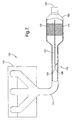
- the regeneration system 10 includes a source of exhaust stream such as from a engine 12 and an exhaust conduit 14 in fluid communication with the engine 12.
- the exhaust conduit 14 is further in fluid communication with a particulate filter 16 and comprises an exhaust valve device 18 disposed upstream from the particulate filter 16.
- the valve device 18 shown is a throttle valve, although other valve and flow restrictors can be employed, such as iris valves, butterfly valves, slider valves, and the like.
- the particulate filter 16 includes a housing 20 that contains one or more filter elements 22.
- the housing 20 is disposed in fluid communication with the exhaust conduit 14 such that a flow of the exhaust stream from the engine to the particulate filter 16 may occur.
- the housing 20 further includes an outlet 24 for discharging the filter exhaust gas stream from the particulate filter 16 to a catalytic converter, to another particulate filter, to a non-thermal plasma reactor, to the atmosphere, or to a combination of devices comprising at least one of the foregoing.
- the exhaust throttle valve device 18 generally includes a shutter portion 30 and a control conduit 32. As shown more clearly in Figures 2 and 3, the exhaust throttle valve device 18 further comprises an actuator 34, a support member 36 and one or more shutter blades 38 extending from the support member 36.
- the actuator 34 provides a triggering signal for opening and closing the shutter blades.
- Figure 2 illustrates the shutter blades 38 in a closed position, wherein the shutter blades 38 cooperatively communicate to restrict or substantially restrict fluid communication from the engine 12 to an inlet 40 of the control conduit 32.
- Figure 3 illustrates the shutter portion 30 in an open position, wherein the shutter blades 38 cooperatively communicate to permit fluid communication from the engine 12 through a cross-sectional area provided by the control conduit 32 as well as the main exhaust conduit 14.
- the actuator 34 can comprise an electrical circuit (not shown) for receiving and transmitting a triggering signal to cause the blades 38 to open and close.
- the actuator 34 can comprise a vacuum mechanism for opening and closing the blades 38, wherein the vacuum mechanism sends a triggering signal in response to a vacuum change resulting from a change in exhaust gas stream flow rate from the engine 12 into the exhaust conduit 14.
- the regeneration caused by the restriction of the exhaust stream flow to the control conduit 32 can be initiated based upon several factors (e.g., triggering signal(s)) or combination of factors, e.g., exhaust stream flow rate, pressure differential across the particulate filter, exhaust temperature, time based, engine idle speed, and the like.
- the control conduit 32 is disposed within the exhaust conduit 14 and extends along a length of the conduit 14.
- the control conduit 32 is supported by the shutter portion 30 at one end or is secured to an interior wall of the exhaust conduit 14.
- the control conduit 32 is positioned such that the inlet 40 extends at or beyond a plane maintained by the shutter blades 38 in a closed position. In this manner, the shutter blades 38 can sealingly close or form a barrier about an outer perimeter of the control conduit 32.
- An outlet 42 of the control conduit 32 is positioned at or near the filter element 22 of the particulate filter 16.
- the control conduit 32 may further be connected along its length to the interior wall of the exhaust conduit 14 by means of a support (or plurality of supports 26 (see Figure 4)) such as a hanger, weld, bar, divider, or the like.
- a support or plurality of supports 26 (see Figure 4)
- the control conduit and exhaust conduit can have various designs and can be produced in various fashions.
- the exhaust conduit 44 can be the main exhaust conduit, with the control conduit 32 formed by a divider 28 and comprising a portion of the exhaust conduit 44 (e.g., half, a third, a quarter, or any other desired portion of the conduit), with the remainder of the conduit 8 capable of being closed, for example with a shutter portion (not shown).
- control conduit 32 can enhance the flow of the exhaust gas, but since only a single conduit is employed (namely exhaust conduit 44 which is divided into sections 32 and 8), the insulating effect obtained by having control conduit 32 as a separate conduit disposed within the exhaust conduit 14 (see Figures 1-4 and 6), is not realized.
- an inner diameter D2 of the control conduit 32 is smaller than the inner diameter D1 of the exhaust conduit 14.
- the size of inner diameter D2 is selected to provide a reduced residence time for the exhaust gas stream when the shutter blades 38 are in the closed position compared to the residence time experienced when the shutter blades are in the open position under the same idle or load conditions.
- Inner diameter D2 is preferably less than or equal to about 50% of D1, with less than or equal to about 40% of D1 more preferred, with less than or equal to about 30% of D1 even more preferred, with less than or equal to about 20% most preferred.
- the lower limit of D1 is based upon the desired gas flow rate and quantity of gas.
- FIG. 7 Another embodiment of a particulate filter regeneration system is shown in Figure 7.
- the system generally designated 100, includes an exhaust throttle valve device 118.
- the exhaust throttle device 118 generally comprises a pivotable shutter 130 and a partition 132.
- the partition 132 extends along a portion of a length of the exhaust conduit 14 and the particulate filter 16 to form two fluid conduits 134, 136. Preferably, the partition extends through the particulate filter 16.
- the pivotable shutter 130 is disposed in a selected one of the conduits. The other conduit, without the pivotable shutter, will be referred to as a control conduit for this system 100.
- the partition 132 may take the form of any shape in defining the fluid conduits 134, 136.
- partition 132 is generally planar and substantially parallel to the exhaust conduit 14. The partition 132 is secured to the interior of the exhaust conduit 14 by a weld or the like.
- control conduit 134 is preferably less than or equal to about 50% of the other fluid passageway 136, with less than or equal to about 40% more preferred, with less than or equal to about 30% even more preferred, with less than or equal to about 20% most preferred. Again, the lower limit is based upon the desired gas flow rate and quantity of gas.
- the pivotable shutter 130 is disposed in a selected one of the fluid conduits 134, 136.
- the pivotable shutter 130 is disposed in the conduit with the greatest cross-sectional flow area.
- the pivotable shutter 130 includes at least one blade 138 extending from a pivot point 140.
- the blade 138 is preferably planar and has a shape that, in the closed position, generally conforms to the cross-sectional shape of the fluid conduit in which it is disposed.
- the pivot point 140 is centrally located between two blades 138 extending coaxially from the pivot point 140.
- the pivot point 140 may be located off-center with blades 138 of unequal lengths extending coaxially therefrom, or the pivot point 140 may be located on a interior surface of the exhaust conduit 114 or on a surface of the partition 132 such that one blade 138 extends therefrom, or the like.
- An actuator (not shown) is in operable communication with the pivotable shutter 130 for providing a trigger signal to pivot the blade 138 about pivot point 140. In this manner, the blade 138 may be pivoted to an open or closed position.
- Figure 8 illustrates the exhaust throttle valve device 118 with blades 138 in a closed position.
- Figure 9 illustrates the exhaust throttle valve device 118 with the blades 138 in an open position.
- At least one filter element 122 is disposed in fluid communication with fluid conduit 134 whereas at least one filter element 123 is disposed in fluid communication with fluid conduit 136, wherein filters 122 and 123 may comprise the same filter.
- the filter elements 122, 123 generally conform to the cross-sectional shape defined by the respective fluid conduit 134, 136 in which they are positioned.
- a section of an exhaust conduit comprising separate exhaust gas conduits.
- the exhaust throttle valve device 230 having a pivot point 240 and blades 238 is disposed in the second conduit 215.
- the second conduits 215, and the control conduit 232 can be disposed in fluid communication with a single particulate filter or with multiple filters (not shown). These filters can be in fluid communication with one another or can solely be in fluid communication with the respective conduit 232 or 215.
- one particulate filter can be in fluid communication with control conduit 232, while a second filter can be in fluid communication with a different particulate filter.
- the exhaust gas would be directed through the control conduit 232 to the associated particulate filter.
- the second conduit 232, as well as the second particulate filter would not be in fluid communication with the exhaust gas, and the exhaust throttle valve device 230 would be in the closed position.
- the design and materials for the exhaust conduit 14, the particulate filter housing 20 should be compatible with the environment in which they will be employed.
- the exhaust conduit 14, the particulate filter housing 20, the control conduit 32 and the partition 132 are preferably constructed from materials that are substantially inert to the operating environment and to the exhaust gas stream. Suitable materials include ferrous materials, e.g., steel, stainless steel, and the like. Meanwhile, the gauge or thickness of the exhaust conduit 14, particulate filter housing 20, control conduit 32 or partition 132 should be sufficient to provide adequate support and stability to the conduit during operation of the engine 12.
- the exhaust conduit 14 preferably has a substantially circular cross-sectional shape.
- the exhaust conduit 14 may further include brackets, hangers, or the like, for attachment of the exhaust conduit 14to a vehicle or the like.
- the filter elements 22, 122, 123 contained within the particulate filter housing 20 may be made of any material suitable for trapping and holding particulate material carried by the exhaust stream.
- the filter elements 22, 122, 123 are fabricated from materials that are capable of withstanding the elevated temperatures reached during the heavy load operation of the engine 12 as well as during particulate filter regeneration.
- the filter elements 22, 122, 123 are fabricated from materials that withstand temperatures less than or equal to 600°C.
- Materials suitable for use as the filter element 22, 122, 123 include ceramics, metals, and the like, as well as oxides, cermets, alloys, and combinations comprising at least one of the foregoing materials.
- filter materials can be in the form of beads, monolithic structures, wire mesh or multiple screen elements (coated and uncoated), and the like, as well as combinations comprising at least one of the foregoing forms.
- Suitable metal materials include steel, stainless steel, and the like.
- Suitable ceramic materials include, alumina, and the like.
- the filter can comprise ceramic coated metal wire mesh, a monolithic ceramic structure, ceramic beads, and combinations comprising at least one of the foregoing.
- the engine 12 is generally operated under two different conditions, an idle condition such as when the motor vehicle is stopped or at a low load and a load condition such as when the motor vehicle is accelerating (e.g., at load of greater than or equal to about 20% of maximum load for that engine).
- the particulate regeneration systems 10, 100 maintain the exhaust gas stream entering the particulate filter 16 at a temperature sufficient to effect regeneration of the respective filter elements 22, 122, 123 under these different operating conditions, while low enough to prevent degradation of the filter. That is, the temperature of the exhaust gas stream entering the filter elements 22, 122, 123, is at a temperature effective to combust particulate matter collected thereby.
- the temperature of the exhaust gas stream as it enters the particulate filter 16 is preferably maintained at a temperature greater than or equal to about 350°C, with a temperature of greater than or equal to about 375°C more preferred. In order to prevent system degradation caused by excessive heat, it is also preferred that the temperature of the exhaust gas stream entering the particulate filter 16 be maintained at a temperature less than or equal to about 550°C, and with less than or equal to about 500°C more preferred.
- Operating particulate regeneration systems 10, 100 can include programming the exhaust throttle valve devices 18, 118 to open and close the respective shutter blades 38, 138 based upon the operating condition (e.g., idle or load; or a particular level of idle or load), exhaust temperature, pressure differential across the particulate filter, or may be time-based.
- the actuator 34 can be programmed to provide a triggering signal under predetermined idle conditions to move the blades 38, 138 to a closed position (or partially closed position) in the exhaust conduit 14. As a result, the flow of the exhaust gas stream is restricted substantially to the control conduit 32, 134.
- the flow rate of the exhaust gas stream through the control conduit 32, 134 increases significantly.
- the increase in flow rate reduces the residence time of the exhaust gas stream within control conduit 32, 134, (i.e., reducing travel time from the engine outlet to the particulate filter inlet), and thereby minimizing thermal loss. Since thermal loss is minimized, the exhaust gas stream can be maintained at a temperature effective to regenerate the filter elements contained in the particulate filter 16 under idle conditions.
- the exhaust conduit 14 further functions as an insulator to control conduit 32.
- the exhaust conduit 14 provides a barrier to the control conduit 32 from direct contact with the external environment.
- the conduit 14 functions as an insulator, further minimizing thermal losses in the exhaust gas stream.
- the exhaust gas stream discharged from the control conduit 32, 134, 232 into the particulate filter 16 is at a temperature effective to combust the particulate matter collected by the respective filter element 22, 122.
- the thermal capacity of the filter element 122 is relatively small due to its relatively small size compared to the total cross sectional area of the exhaust conduit 14, regeneration of substantially the entire surface area of the filter element 122 may occur.
- the actuator can be programmed to pivotably move the shutter blades 38, 138 to an open position (as shown in Figures 3, 9, respectively) or to a partially open position.
- the open position the flow of the exhaust gas stream is unrestricted and flows through all of the fluid passageways, e.g., 14, 32, 134, 136.
- the temperature of the exhaust gas stream is effective to cause combustion of the particulate matter collected by filter elements 22, 122, 123.
- the blades 38 can be partially closed to restrict the flow to the control conduit and to maintain the exhaust gas at a desired exhaust gas temperature (i.e., reduce the thermal losses of the exhaust gas stream as it flow from the engine outlet to the filter inlet).
- the system can regenerate and/or light-off the exhaust emission control device under different operating conditions, e.g., idle or load conditions. For example, even at idle, light off of a catalyst in a catalytic converter can occur in reduced time, thereby reducing emissions. Also, clogging of a particulate filter, sulfur trap, or the like, can be prevented during operation, thereby preventing buildup of backpressure to an engine and other problems caused by clogging of the exhaust emission control device. Similarly, poisoning of a catalyst in a catalytic converter is prevented due to the regeneration.
- the system is relatively simple, inexpensive to install and provides a reliable process for regenerating and/or attaining light-off of an exhaust emission control device. Moreover, the system does not require the use of an auxiliary heater.
- This system further enables control of the exhaust gas temperature.
- the residence time of gas passing through the conduit can be reduced, thereby reducing the temperature drop of the gas as it passes through the exhaust conduit.
- the means for restricting the flow e.g., the restricting device
- Controlling of the restricting device can be with various mechanical, electrical and/or software devices, including sensors, computers, software, and the like.
Landscapes
- Engineering & Computer Science (AREA)
- Chemical & Material Sciences (AREA)
- Combustion & Propulsion (AREA)
- Mechanical Engineering (AREA)
- General Engineering & Computer Science (AREA)
- Chemical Kinetics & Catalysis (AREA)
- Health & Medical Sciences (AREA)
- Toxicology (AREA)
- Processes For Solid Components From Exhaust (AREA)
- Exhaust Gas After Treatment (AREA)
Abstract
Description
Claims (25)
- A process for operating an exhaust gas system (10, 100), comprising:wherein the flow is sufficiently restricted such that the exhaust gas stream discharged into the exhaust emission control device (18, 118, 230) has a temperature perform a desired function selected from the group consisting of regeneration and light-off.producing an exhaust gas flow;introducing the exhaust gas flow to a system (10, 100) comprising a restricting device in fluid communication with an exhaust emission control device (18, 118, 230), and an exhaust conduit (14, 44, 114) comprising an exhaust throttle device (18, 118, 230);restricting the flow of the exhaust gas stream to the restricting device (18, 118, 230); anddischarging the exhaust gas stream from the restricting device into the exhaust emission control device (18, 118, 230);
- The process for operating an exhaust gas system (10, 100) according to Claim 1, wherein the flow is restricted when an engine (12) producing the exhaust gas stream is operating at idle.
- The process for operating an exhaust gas system (10, 100) according to Claim 1, wherein the flow is restricted based upon a vacuum level produced from the flow of the exhaust gas stream through the exhaust conduit (14, 44, 114).
- The process for operating an exhaust gas system (10, 100) according to Claim 1, further comprising unrestricting the flow of the exhaust gas stream through the exhaust conduit (14, 44, 114) when an engine (12) producing the exhaust gas stream is operating under a load.
- The process for operating an exhaust gas system (10, 100) according to Claim 4, further comprising producing the exhaust gas stream, and wherein the load is greater than or equal to about 20% of a maximum load for the engine (12).
- The process for operating an exhaust gas system (10, 100) according to Claim 1, further comprising restricting the flow at timed intervals.
- The process for operating an exhaust gas system (10, 100) according to Claim 1, further comprising producing the exhaust gas stream, sensing an operating load of the engine (12), and restricting the flow based upon the operating load.
- The process for operating an exhaust gas system (10, 100) according to Claim 1, further comprising sensing an exhaust stream temperature at an inlet (40) of the exhaust emission control device (18, 118, 230) and restricting the flow based upon the exhaust stream temperature.
- The process for operating an exhaust gas system (10, 100) according to Claim 1, wherein the restricting device and the exhaust gas conduit are separate conduits.
- The process for operating an exhaust gas system (10, 100) according to Claim 1, wherein the exhaust gas conduit is in fluid communication with a second emission control device (18, 118, 230) and the restricting device is only in fluid communication with the exhaust emission control device (18, 118, 230).
- The process for operating an exhaust gas system (10, 100) according to Claim 1, wherein the exhaust emission control device (18, 118, 230) is selected from the group consisting of catalytic converters, scrubbing devices, particulate filters/traps (16), adsorbers, and absorbers.
- An exhaust system (10, 100), comprising:a restricting device disposed in an exhaust conduit (14, 44, 114) and in fluid communication with a exhaust emission control device (18, 118, 230); anda second emission control device (18, 118, 230) disposed in fluid communication with the exhaust conduit (14, 44, 114) and downstream from the exhaust throttle device (18, 118, 230).
- The system (10, 100) according to Claim 12, wherein the restricting device is a control conduit (32, 232) having a cross-sectional area less than or equal to about 50% of a cross-sectional area of the exhaust conduit (14, 44, 114).
- The system (10, 100) according to Claim 13, wherein the control conduit (32, 232) (8) cross-sectional area is less than or equal to about 40% of the cross-sectional area of the exhaust conduit (14, 44, 114).
- The system (10, 100) according to Claim 14, wherein the control conduit (32, 232) cross-sectional area is less than or equal to about 30% of the cross-sectional area of the exhaust conduit (14, 44, 114).
- The system (10, 100) according to Claim 15, wherein the control conduit (32, 232) cross-sectional area is less than or equal to about 20% of the cross-sectional area of the exhaust conduit (14, 44, 114).
- The system (10, 100) according to Claim 13, wherein the control conduit (32, 232) and the exhaust conduit (14, 44, 114) are separate conduits.
- The system (10, 100) according to Claim 17, wherein the control conduit (32, 232) further comprises an inlet (40) extending at or beyond a plane defined by the shutter portion (30).
- The system (10, 100) of Claim 13, wherein the control conduit (32, 232) and the exhaust conduit (14, 44, 114) comprise a single conduit with a divider (28) disposed therein.
- The system (10, 100) according to Claim 12, wherein the exhaust conduit (14, 44, 114) further comprises an exhaust throttle device (18, 118, 230) comprising a shutter portion (30).
- The system (10, 100) according to Claim 20, wherein the control conduit (32, 232) is disposed within the exhaust gas conduit and is formed by a partition (132) disposed in the exhaust conduit (14, 44, 114), with the shutter portion (30) disposed on a side of the partition (132) opposite the control conduit (32, 232).
- The system (10, 100) according to Claim 21, wherein the partition (132) at least partially extends through the exhaust emission control device (18, 118, 230).
- The system (10, 100) according to Claim 20, wherein the shutter further comprises at least one blade pivotable about a pivot point (140, 240).
- The system (10, 100) according to Claim 20, wherein the shutter portion (30) further comprises an actuator (34), a support member (36) and a blade, and wherein the actuator (34) is in operable communication with the blade.
- An exhaust system (10, 100), comprising:an exhaust conduit (14, 44, 114) in fluid communication an outlet (24, 42) of an engine (12) and with a exhaust emission control device (18, 118, 230);a means for restricting flow in the exhaust conduit (14, 44, 114) under selected conditions; anda means for controlling the means for restricting flow.
Applications Claiming Priority (2)
| Application Number | Priority Date | Filing Date | Title |
|---|---|---|---|
| US10/444,576 US20040231323A1 (en) | 2003-05-23 | 2003-05-23 | Exhaust system and process for operating the same |
| US444576 | 2003-05-23 |
Publications (2)
| Publication Number | Publication Date |
|---|---|
| EP1479884A2 true EP1479884A2 (en) | 2004-11-24 |
| EP1479884A3 EP1479884A3 (en) | 2006-07-12 |
Family
ID=33098032
Family Applications (1)
| Application Number | Title | Priority Date | Filing Date |
|---|---|---|---|
| EP04076356A Withdrawn EP1479884A3 (en) | 2003-05-23 | 2004-05-05 | An exhaust system and process for operating the same |
Country Status (2)
| Country | Link |
|---|---|
| US (1) | US20040231323A1 (en) |
| EP (1) | EP1479884A3 (en) |
Cited By (3)
| Publication number | Priority date | Publication date | Assignee | Title |
|---|---|---|---|---|
| FR2944555A1 (en) * | 2009-04-16 | 2010-10-22 | Peugeot Citroen Automobiles Sa | Particle filter for use in exhaust line of internal combustion engine i.e. diesel engine, of motor vehicle, has selective treating unit whose implementation is performed based on dependency of analysis unit for driving mode of motor vehicle |
| CN103026019A (en) * | 2010-05-27 | 2013-04-03 | 万国引擎知识产权有限责任公司 | Method for operating an exhaust valve for diesel particulate filter regeneration |
| CN104234789A (en) * | 2013-06-17 | 2014-12-24 | 福特环球技术公司 | System and method for a movable exhaust aftertreatment device in an internal combustion engine |
Families Citing this family (12)
| Publication number | Priority date | Publication date | Assignee | Title |
|---|---|---|---|---|
| JP4175282B2 (en) * | 2004-03-31 | 2008-11-05 | いすゞ自動車株式会社 | Exhaust gas purification system control method and exhaust gas purification system |
| JP4100449B1 (en) * | 2007-01-26 | 2008-06-11 | いすゞ自動車株式会社 | Exhaust gas purification system control method and exhaust gas purification system |
| US7743604B1 (en) | 2007-03-23 | 2010-06-29 | Daniel Albanesi | Apparatus for heating the dump body of a dump truck having a diesel particulate filter |
| WO2009081231A1 (en) * | 2007-12-21 | 2009-07-02 | Renault Trucks | Thermal energy containing arrangement for an exhaust gas purification device |
| AT506338A1 (en) * | 2008-02-04 | 2009-08-15 | Man Nutzfahrzeuge Oesterreich | METHOD FOR REGENERATING A PARTICULATE FILTER ARRANGED IN THE EXHAUST GAS TRAY OF A VEHICLE DIESEL ENGINE |
| JP4737230B2 (en) * | 2008-05-23 | 2011-07-27 | トヨタ自動車株式会社 | Waste heat recovery system |
| US8631642B2 (en) | 2009-12-22 | 2014-01-21 | Perkins Engines Company Limited | Regeneration assist calibration |
| US20110146246A1 (en) * | 2009-12-22 | 2011-06-23 | Caterpillar Inc. | Regeneration assist transition period |
| US9273594B2 (en) | 2014-02-20 | 2016-03-01 | Electro-Motive Diesel, Inc. | Dual-fuel engine system with backpressure control |
| JP6251117B2 (en) * | 2014-04-28 | 2017-12-20 | フタバ産業株式会社 | Silencer |
| KR101795276B1 (en) * | 2016-06-20 | 2017-11-08 | 현대자동차주식회사 | Method for controlling air control valve |
| JP7178219B2 (en) * | 2018-09-10 | 2022-11-25 | 三菱重工エンジン&ターボチャージャ株式会社 | Control device, exhaust gas purification system, and engine control method |
Family Cites Families (11)
| Publication number | Priority date | Publication date | Assignee | Title |
|---|---|---|---|---|
| JPS58101210A (en) * | 1981-12-10 | 1983-06-16 | Nippon Soken Inc | Exhaust gas particle purifier in internal-combustion engine |
| CH663253A5 (en) * | 1984-04-11 | 1987-11-30 | Bbc Brown Boveri & Cie | Exhaust particle filter for internal combustion engines |
| US5067319A (en) * | 1989-02-15 | 1991-11-26 | Steyr-Daimler-Puch Ag | System for purifying the exhaust gases of diesel engines |
| AU2246092A (en) * | 1991-06-27 | 1993-01-25 | Donaldson Company Inc. | Trap apparatus with tubular filter element |
| US5582003A (en) * | 1994-04-28 | 1996-12-10 | Corning Incorporated | Temperature actuated zeolite in-line adsorber system |
| EP0687805B1 (en) * | 1994-05-17 | 1998-05-06 | Isuzu Ceramics Research Institute Co., Ltd. | Diesel particulate filter |
| US5582002A (en) * | 1994-06-29 | 1996-12-10 | Pattas; Konstantin | Method of and an apparatus for controlled regeneration of a diesel soot filter |
| US5787707A (en) * | 1994-08-02 | 1998-08-04 | Corning Incorporated | In-line adsorber system |
| DE19507977A1 (en) * | 1995-03-07 | 1996-09-12 | Schatz Thermo Gastech Gmbh | Method and arrangement for reducing the exhaust gas emissions of internal combustion engines with exhaust gas catalysts |
| JP2003516493A (en) * | 1999-12-08 | 2003-05-13 | フオルクスワーゲン・アクチエンゲゼルシヤフト | Apparatus for supplying exhaust gas from a combustion engine to a catalytic device, especially a storage catalytic device |
| DE10143806B4 (en) * | 2001-09-06 | 2004-11-25 | Daimlerchrysler Ag | Emission control system for an internal combustion engine, in particular for a motor vehicle |
-
2003
- 2003-05-23 US US10/444,576 patent/US20040231323A1/en not_active Abandoned
-
2004
- 2004-05-05 EP EP04076356A patent/EP1479884A3/en not_active Withdrawn
Cited By (5)
| Publication number | Priority date | Publication date | Assignee | Title |
|---|---|---|---|---|
| FR2944555A1 (en) * | 2009-04-16 | 2010-10-22 | Peugeot Citroen Automobiles Sa | Particle filter for use in exhaust line of internal combustion engine i.e. diesel engine, of motor vehicle, has selective treating unit whose implementation is performed based on dependency of analysis unit for driving mode of motor vehicle |
| CN103026019A (en) * | 2010-05-27 | 2013-04-03 | 万国引擎知识产权有限责任公司 | Method for operating an exhaust valve for diesel particulate filter regeneration |
| CN103026019B (en) * | 2010-05-27 | 2016-03-16 | 万国引擎知识产权有限责任公司 | Method of operation of an exhaust throttle valve for regeneration of a diesel particulate filter |
| CN104234789A (en) * | 2013-06-17 | 2014-12-24 | 福特环球技术公司 | System and method for a movable exhaust aftertreatment device in an internal combustion engine |
| CN104234789B (en) * | 2013-06-17 | 2018-07-03 | 福特环球技术公司 | For the system and method for exhaust gas post-treatment device moveable in internal combustion engine |
Also Published As
| Publication number | Publication date |
|---|---|
| EP1479884A3 (en) | 2006-07-12 |
| US20040231323A1 (en) | 2004-11-25 |
Similar Documents
| Publication | Publication Date | Title |
|---|---|---|
| US7273514B2 (en) | Apparatus and method for filtering particulate and NOx emissions | |
| US20040231323A1 (en) | Exhaust system and process for operating the same | |
| EP3423687B1 (en) | Heater-actuated flow bypass | |
| US5357755A (en) | Trap apparatus with bypass | |
| US7337609B2 (en) | Diesel exhaust system variable backpressure muffler | |
| US6742331B2 (en) | Device for purifying exhaust gas of diesel engines | |
| US5582002A (en) | Method of and an apparatus for controlled regeneration of a diesel soot filter | |
| US20030110761A1 (en) | Exhaust emission purification system for diesel engine | |
| JPH07189655A (en) | Engine exhaust purification device | |
| US7444803B2 (en) | Exhaust gas control apparatus for engine and method for producing same | |
| US20070079606A1 (en) | Diesel vehicle exhaust aftertreatment apparatus and method | |
| JPH08189340A (en) | Diesel particulate filter device with bypass pipe with sound deadening function | |
| JPH0610409B2 (en) | Engine smoke reduction device | |
| JPH0286910A (en) | Exhaust gas purification device for internal combustion engine using alcohol | |
| JPH0610410B2 (en) | How to reduce engine smoke | |
| JP2007255395A (en) | Exhaust pressure control valve | |
| JPH07659Y2 (en) | Exhaust gas aftertreatment device | |
| JP2000213329A (en) | Exhaust gas purification device for internal combustion engine | |
| JP2021131038A (en) | Exhaust system structure | |
| JPH0422011Y2 (en) | ||
| JPS6038018Y2 (en) | Diesel engine exhaust particulate purification device | |
| JP2021131062A (en) | Exhaust system structure | |
| JPH02259221A (en) | Cartridge exchange type soot collector device for diesel engine | |
| JPH07102951A (en) | Exhaust purification device | |
| JP2002081310A (en) | DPF device |
Legal Events
| Date | Code | Title | Description |
|---|---|---|---|
| PUAI | Public reference made under article 153(3) epc to a published international application that has entered the european phase |
Free format text: ORIGINAL CODE: 0009012 |
|
| AK | Designated contracting states |
Kind code of ref document: A2 Designated state(s): AT BE BG CH CY CZ DE DK EE ES FI FR GB GR HU IE IT LI LU MC NL PL PT RO SE SI SK TR |
|
| AX | Request for extension of the european patent |
Extension state: AL HR LT LV MK |
|
| PUAL | Search report despatched |
Free format text: ORIGINAL CODE: 0009013 |
|
| AK | Designated contracting states |
Kind code of ref document: A3 Designated state(s): AT BE BG CH CY CZ DE DK EE ES FI FR GB GR HU IE IT LI LU MC NL PL PT RO SE SI SK TR |
|
| AX | Request for extension of the european patent |
Extension state: AL HR LT LV MK |
|
| 17P | Request for examination filed |
Effective date: 20070112 |
|
| AKX | Designation fees paid |
Designated state(s): AT BE BG CH CY CZ DE DK EE ES FI FR GB GR HU IE IT LI LU MC NL PL PT RO SE SI SK TR |
|
| 17Q | First examination report despatched |
Effective date: 20081106 |
|
| STAA | Information on the status of an ep patent application or granted ep patent |
Free format text: STATUS: THE APPLICATION IS DEEMED TO BE WITHDRAWN |
|
| 18D | Application deemed to be withdrawn |
Effective date: 20081202 |