EP1479873A2 - Steam turbine - Google Patents
Steam turbine Download PDFInfo
- Publication number
- EP1479873A2 EP1479873A2 EP04012098A EP04012098A EP1479873A2 EP 1479873 A2 EP1479873 A2 EP 1479873A2 EP 04012098 A EP04012098 A EP 04012098A EP 04012098 A EP04012098 A EP 04012098A EP 1479873 A2 EP1479873 A2 EP 1479873A2
- Authority
- EP
- European Patent Office
- Prior art keywords
- steam
- turbine
- cooling
- cooling steam
- cover plate
- Prior art date
- Legal status (The legal status is an assumption and is not a legal conclusion. Google has not performed a legal analysis and makes no representation as to the accuracy of the status listed.)
- Granted
Links
Images


Classifications
-
- F—MECHANICAL ENGINEERING; LIGHTING; HEATING; WEAPONS; BLASTING
- F02—COMBUSTION ENGINES; HOT-GAS OR COMBUSTION-PRODUCT ENGINE PLANTS
- F02C—GAS-TURBINE PLANTS; AIR INTAKES FOR JET-PROPULSION PLANTS; CONTROLLING FUEL SUPPLY IN AIR-BREATHING JET-PROPULSION PLANTS
- F02C7/00—Features, components parts, details or accessories, not provided for in, or of interest apart form groups F02C1/00 - F02C6/00; Air intakes for jet-propulsion plants
- F02C7/12—Cooling of plants
- F02C7/16—Cooling of plants characterised by cooling medium
-
- F—MECHANICAL ENGINEERING; LIGHTING; HEATING; WEAPONS; BLASTING
- F01—MACHINES OR ENGINES IN GENERAL; ENGINE PLANTS IN GENERAL; STEAM ENGINES
- F01D—NON-POSITIVE DISPLACEMENT MACHINES OR ENGINES, e.g. STEAM TURBINES
- F01D25/00—Component parts, details, or accessories, not provided for in, or of interest apart from, other groups
- F01D25/08—Cooling; Heating; Heat-insulation
- F01D25/14—Casings modified therefor
-
- F—MECHANICAL ENGINEERING; LIGHTING; HEATING; WEAPONS; BLASTING
- F05—INDEXING SCHEMES RELATING TO ENGINES OR PUMPS IN VARIOUS SUBCLASSES OF CLASSES F01-F04
- F05D—INDEXING SCHEME FOR ASPECTS RELATING TO NON-POSITIVE-DISPLACEMENT MACHINES OR ENGINES, GAS-TURBINES OR JET-PROPULSION PLANTS
- F05D2260/00—Function
- F05D2260/20—Heat transfer, e.g. cooling
- F05D2260/201—Heat transfer, e.g. cooling by impingement of a fluid
-
- F—MECHANICAL ENGINEERING; LIGHTING; HEATING; WEAPONS; BLASTING
- F05—INDEXING SCHEMES RELATING TO ENGINES OR PUMPS IN VARIOUS SUBCLASSES OF CLASSES F01-F04
- F05D—INDEXING SCHEME FOR ASPECTS RELATING TO NON-POSITIVE-DISPLACEMENT MACHINES OR ENGINES, GAS-TURBINES OR JET-PROPULSION PLANTS
- F05D2260/00—Function
- F05D2260/20—Heat transfer, e.g. cooling
- F05D2260/205—Cooling fluid recirculation, i.e. after cooling one or more components is the cooling fluid recovered and used elsewhere for other purposes
-
- F—MECHANICAL ENGINEERING; LIGHTING; HEATING; WEAPONS; BLASTING
- F05—INDEXING SCHEMES RELATING TO ENGINES OR PUMPS IN VARIOUS SUBCLASSES OF CLASSES F01-F04
- F05D—INDEXING SCHEME FOR ASPECTS RELATING TO NON-POSITIVE-DISPLACEMENT MACHINES OR ENGINES, GAS-TURBINES OR JET-PROPULSION PLANTS
- F05D2260/00—Function
- F05D2260/20—Heat transfer, e.g. cooling
- F05D2260/232—Heat transfer, e.g. cooling characterized by the cooling medium
- F05D2260/2322—Heat transfer, e.g. cooling characterized by the cooling medium steam
Definitions
- This invention relates to a steam turbine, and in particular a steam turbine that permits operation with an increased steam temperature.
- Conventional steam turbine plants generally introduce a one-stage reheating configuration using reheated steam.
- steam at a temperature of about 1000 degrees Fahrenheit is used for a high pressure turbine, while steam at a temperature of 1000 or 1050 degrees Fahrenheit is used for an intermediate pressure turbine as reheated steam.
- the Rankine cycle which is a thermal cycle generally used in a steam turbine plant
- the plant thermal efficiency can be more improved.
- a conventional high pressure turbine and intermediate pressure turbine for a steam turbine plant is described in Japanese Patent Application (Kokai) No. 11-350911.
- the intermediate pressure turbine uses steam at a temperature about 1100 degrees Fahrenheit as reheated steam, the turbine having a reheated steam supply tube with a steam-cooled double-tubing structure.
- a nozzle box is a chamber for steam that is supplied from a boiler or the like and supplying those steam to turbine stages.
- a nozzle box also has a function to avoid constituent components surrounding the nozzle box from directly being exposed to a high temperature steam.
- high pressure steam turbine has a nozzle box in a inlet side of steam, however, it is designed to maintain a strength with steam at a temperature of 1050 to 1100 degrees Fahrenheit. It is difficult to maintain a strength with steam at a temperature of 1300 degrees or above Fahrenheit for a conventional nozzle box. And for those high temperature steam, a radiation problem is to be considered. When adopting steam at about 1300 degrees Fahrenheit, a heat transfer by radiation is not negligible because a temperature of outer surfaces of the nozzle box becomes high. The radiation heat heat heats up constituent components, such as a casing and a turbine rotor, that are provided around the nozzle box.
- an advantage of an aspect of the present invention is to provide a steam turbine that can effectively operate with the steam at the higher temperatures, while maintaining the strength of turbine constituent components despite the high steam temperature of the steam.
- one aspect of the present invention is to provide a steam turbine that may comprises a casing, a rotor rotatably installed in the casing, a plurality of turbine stages disposed in the turbine, at least one of the turbine stages including a turbine nozzle and including a moving blade that is fixed to'the rotor, a steam pass including the at least one turbine stage, a nozzle box, which is placed in a space between the casing and the rotor, for providing a heated steam into the steam pass, and a cover plate, which is arranged along outside of the nozzle box.
- FIG. 1 is a schematic vertical cross sectional view showing an embodiment of a steam turbine according to the present invention.
- an intermediate pressure turbine 2 has a double casing structure including an outer casing 32 and an inner casing 33.
- Turbine rotor 34 is rotatably installed in inner casing 33.
- Turbine rotor 34 has a plurality of moving blades 30.
- Inner casing 33 supports a plurality of nozzles 29 by nozzle diaphragm in its inside portion.
- Nozzle 29 and moving blade 30 are adjacently arranged to each other in its radial position against the center axis of turbine rotor 34.
- a turbine stage 28 consist of one nozzle 29 and one moving blade 30.
- a plurality of the turbine stage 28 are provided as a steam pass, which is a pathway of high temperature steam introduced to intermediate pressure turbine 2.
- a nozzle box 31 is provided in a space between turbine rotor 34 and inner casing 33, as it surrounds turbine rotor 34.
- Intermediate pressure turbine 2 has steam inlet tube 27, which supplies high temperature steam, which is reheated steam in this example, to the nozzle box 31.
- Nozzle box 31 is a steam chamber that supplies high temperature steam form steam inlet tube 27 to turbine stages 28, which is the steam pass.
- the cooling steam is supplied to nozzle box 31 by cooling steam line 70.
- Fig. 2 shows, in a cross sectional view, a more detailed depiction of the nozzle box 31 of the intermediate pressure turbine 2 according to the embodiment of the invention.
- Fig. 3 is an enlarged schematic sectional view showing the "X" part on the Fig. 2.
- nozzle box 31 has a square like shape in a cross section, surrounded by a wall 37. Inside the wall 37 is a steam chamber 36.
- Steam supply tube 27 is connected to an upper face, which is a outer circumferential face, of the wall 37 of nozzle box 31.
- nozzle port 35 is formed in another face of wall 37, which fronts onto turbine stage 28.
- a cooling steam path 38 is formed inside wall 37.
- a cooling steam inlet 49 which supplies the cooling steam into cooling steam path 38, is provided in wall 37.
- Cooling steam outlet ports 39 which is a openings that passes the cooling steam inside the cooling steam path 38 through outside of wall 37, is also provided in wall 37.
- Cooling steam supply line 70 is connected to cooling steam inlet 49.
- a plurality of cover plate 41 is arranged along an outer face of wall 37 of nozzle box 31.
- Cover plates 41 are supported by a support 40, as they leave a space between walls 37 of nozzle box 31.
- support 40 fixes cover plate 41 in a predetermined distance from wall 37.
- cover plates 41 are arranged to cover the whole surface of.nozzle box 31, however having a cooling steam outlet openings 45.
- cover plates 41 intermittently cover the whole of nozzle box 31.
- a cooling steam outlet opening 45 is provided in cover plate 41 to pass the cooling steam in a space between walls 37 and cover plate 41 through outside of the.cover plate 41. Cooling steam outlet opening 45 may be formed by utilizing a gap between the cover plate 41.
- cover plate 41 such as heat-resistant flat plate may be used. Since cover plate 41 is accommodated on nozzle box 31 by support 40, the material of the cover plate 41 may preferably be the same material of the nozzle box 31 when considered thermal expansion of the material. Austenite type alley, such as SUS 310, may be used as cover plate, because it has an advantage of antioxidation.
- the cooling steam which is supplied to cooling steam path 38 from cooling steam inlet 49, cools the wall 37 while it flows inside steam path 38.
- the cooling steam then flows out from steam path toward cover plates 41 via cooling steam outlet port 39, and finally flows outside of cover plates 41 via cooling steam outlet opening 45, toward such as turbine rotor 34.
- Cover plate 41 shown in Fig. 3 is a flat plate, however it may be a wave-shaped plate 42 as shown in Fig. 4.
- Fig. 4 is a enlarged schematic sectional view of a corresponding part as the "X" part shown in Fig. 2 when wave-shaped plate 42 is applied to the embodiment.
- Wave-shaped plate 42 as the cover plate may not only effectively absorb a thermal expansion of the cover plate caused by a high temperature, but may also improve a heat transfer coefficient because it has larger surface area than the flat plate.
- cover plates 41 are supported and arranged by supports 40 in a same distance from wall 37 of the nozzle box 31, it may be arranged as some of a cover plate 41a with a support 41a have a larger distance from wall 37 than other cover plates 41b and 41c, which are supported by respective support 40b and 40c, as shown in Fig. 5.
- the pressure of the cooling steam which flows out from cooling steam outlet port 39 at a portion of cover plate 41a, may be recovered more than other portions.
- cover plates 41c, 41b, and 41a may be arranged as the distance from the wall 37 may be gradually enlarged from one side to the another by supports 40c, 40b, and 40a. This may form layers of the cover plates 41c, 41b, and 41a above wall 37, which can be used as outside cooling steam paths 44a and 44b as the cooling steam from cooling steam outlet port 39 cools both face of cover plates 41b and 41c.
- Fig 7 is a schematic cross sectional view showing a modification of a whole of the nozzle box applied in the embodiment of a steam turbine.
- cover plates 41 is arranged as it encloses the outside of wall 37 of nozzle box 31. Cover plates 41 are also supported by a support 40 as shown in Fig. 2.
- Cooling steam outlet ports 46 are also provided in wall 37 to pass the cooling steam from cooling steam path 38 to a space 47 between wall 37 and cover plates 41.
- Cooling steam inlet 49 which supplies the cooling steam to cooling steam path 38, is provided in wall 37.
- Cooling steam outlet 50 which recovers the cooling steam from the space 47, is provided in a cover plate 41.
- Cooling steam supply line 70 is connected to cooling steam inlet 49 and cooling steam recovery line 71 is connected to cooling steam outlet 50.
- recovered cooling steam which is the cooling steam recovered after cooled wall 37 and cover plates 41, may be utilized for other constituent components of a steam turbine plant.
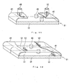
- Fig. 8 is an enlarged schematic perspective view showing a corresponding part as.the "Y" part shown in Fig. 7.
- a cooling steam inlet port 48 which recovers the cooling steam from the space 47 into the cooling steam path 38, are provided in wall 37 other than cooling steam outlet port 46.
- cooling steam inlet port 46 and cooling steam outlet port 48 are preferably provided at each divided space 47a, 47b, ... in the wall 37.
- cover plates 41c, 41b, and 41a are arranged as the distance from the wall 37 may be gradually enlarged from one side to the another by supports 40c, 40b, and 40a. This may form layers of the cover plates 41c, 41b, and 41a, which can be used as outside cooling steam paths 44a, 44b and 44c as the cooling steam from cooling steam outlet port 39 cools both face of cover plates 41b and 41c.
- Figs. 11 and 12 are enlarged schematic perspective views showing modifications of the first embodiment.
- cooling steam inlet 49 which supply the cooling steam into the space 47, is provided in the cover plate 41 instead of the wall 37. This enable the cooling steam directly supplied to the space 47.
- Cooling steam outlet 50 is also provided in cover plate 41. Not shown in Fig. 11, cooling steam path may be provided in the wall 37 of the nozzle box 31.
- partitions 51 may be provided inside the space 47 to divide the space.
- a steam pass opening 52 is provided in each of the partition 51 to supply the cooling steam all over the space 47.
- At least two (2) partitions 51 are preferably provided so as to divide the space 47 into three (3) part.
- the steam pass openings 52 are preferably alternately arranged with each of the partition 51 respectively. This makes the cooling steam meandering inside the space 47.
- the cooling steam may be cool cover plate 41 or wall 37 of nozzle box 31 effectively.
- Partitions 51 and steam pass openings 52 may be applicable to above mentioned configurations as referred to Figs. 7, 8 or 10.
- Fig. 13 is a chart of a temperature distribution between a nozzle box and a turbine rotor.
- the horizontal axis shows position between inside of the wall of the nozzle box and outer surface of the turbine rotor.
- the vertical axis shows a temperature.
- a solid line shows when the cover plates are provided, while two-point dashed line shows when the cover plates are not provided.
- the cover plates are shielding the heat from the high temperature steam supplied to the nozzle box.
- a surface temperature of the turbine rotor is lower when the cover plates are provided. It results to weaken a heat stress of the turbine rotor.
- the nozzle box is effectively cooled by the cooling steam and the cover plates shield a heat transfer, such as a convection or a radiation, from the high temperature steam. Therefore, the steam turbine may effectively operate with the steam at the higher temperatures, while maintaining the strength of turbine constituent components, such as turbine rotor, despite the high steam temperature of the steam.
- the cooling steam is supplied to the nozzle box in the steam turbine.
- a supply of the cooling steam in steam turbine plant utilizing a steam turbine mentioned above is explained below.
- Fig. 14 is a schematic diagram of a example of a steam turbine plant that is suitable to adopt a steam turbine of the embodiment.
- the steam turbine according to the embodiment is applied to the intermediate turbine.
- a steam turbine plant includes a steam turbine 1, a boiler 9 as a steam generator, a condensate system 13 and a feedwater system 14.
- Steam turbine 1 includes an intermediate pressure turbine 2, a high pressure turbine 3, a low pressure turbine 7 having a double-flow type configuration and a generator 8. Rotating shafts of those intermediate pressure turbine 2, high pressure turbine 3, low pressure turbine 7 and generator 8 are connected each other, steam turbine 1 has a one rotating shaft as a whole.
- Boiler 9 as a steam generator, produces high pressure main steam, which is supplied to high pressure turbine 3 through line 12.
- the main steam expands while it flows through the high pressure turbine 3, performing expansion work that drives high pressure turbine 3.
- a high pressure steam bleed line 5 is communicatively connected to high pressure turbine 3 at an intermediate stage of high pressure turbine 3, and bleeds steam from high pressure turbine 3.
- the main steam expanded in high pressure turbine 3 is discharged from high pressure turbine 3 to a low temperature reheat line 10 as high pressure turbine discharged steam.
- the high pressure turbine discharged steam is supplied to boiler 9, reheated by a reheater 11 to produce reheated steam (another form of heated steam) having a temperature, for example, of about 1300 or more degrees Fahrenheit.
- the reheated steam is supplied to intermediate pressure turbine 2 so as to do expansion work and drive intermediate pressure turbine 2.
- a cooling steam supply line 4 is communicatively connected to intermediate pressure turbine 2 at a point relatively upstream of the intermediate pressure turbine 2. Cooling steam supply line 4 introduces part of the steam bled from the high pressure turbine 3 via high pressure steam bleed line 5 as a cooling steam in intermediate pressure turbine 2.
- Intermediate pressure steam bleed lines 60 and 61, which bleed steam from intermediate stages of intermediate pressure turbine 2, are connected to intermediate pressure turbine 2.
- intermediate pressure turbine 2 The reheated steam, as expanded in intermediate pressure turbine 2, is discharged from intermediate pressure turbine 2. This discharged steam is supplied to low pressure turbine 7, where it further expands to drive low pressure turbine 7. In this manner, high pressure turbine 3, intermediate pressure turbine 2, low pressure turbine 7 and generator 8 are all driven by steam. Low pressure steam bleed lines 62, which bleed steam from intermediate stages of low pressure turbine 7, are connected to low pressure turbine 7.
- Condensate system 13 includes a condenser 15, a condensate pump 16, a first low pressure feedwater heater 17, a second low pressure feedwater heater 18, a third low pressure feedwater heater 19, and a fourth low pressure feedwater heater 20.
- Steam discharged from low pressure turbine 7 is introduced and condensed into condensate in condenser 15.
- the condensate is pumped by condensate pump 16 and flows through the low pressure feedwater heaters 17-20 in order, being heated with steam bled supplied from each of low pressure steam bleed lines 62 that are connected to low pressure turbine 7.
- Feedwater system 14 includes a deaerator 21, a feedwater pump 22, a first high pressure feedwater heater 23, a second high pressure feedwater heater 24, a third high pressure feedwater heater 25 and a desuperheater 6 along the stream of the feedwater, downstream from the high pressure feedwater heaters 23-25.
- the condensate supplied from fourth low pressure feedwater heater 20 of the condensate system 13 is heated and deaerated using deaerator 21, where the heating source is steam bled from the intermediate pressure steam bleed line 61 on a relatively downstream part of intermediate pressure turbine 2. Feedwater is formed in this manner.
- Desuperheater 6 is arranged at the most downstream side of feedwater system 14.
- Desuperheater 6 heats feedwater heater using the sensible heat of steam bled in the intermediate pressure steam bleed line 60 connected to a relatively upstream part of intermediate pressure turbine 2. Such steam has a relatively high degree of superheat, as preferable for further heating the feedwater from the third high pressure feedwater heater 25 in feedwater system 14.
- the feedwater is pumped by the feedwater pump 22.
- the water is heated by the first through third high pressure feedwater heaters 23, 24, and 25, in their respective'order.
- the feedwater from third high pressure feedwater heater 25 is supplied to desuperheater 6, where it is further heated.
- First high pressure feedwater heater 23 uses steam flowing from desuperheater 6 as a heating source, which has taken the sensible heat from the steam in the intermediate pressure steam bleed line 60 and has been reduced to close to a saturation temperature in desuperheater 6.
- Second high pressure feedwater heater 24 uses discharged steam from high pressure turbine 3, through line 10, as a heating source.
- Third high pressure feedwater heater 25 uses steam bled from high pressure steam bleed line 5 connected to an intermediate stage of high pressure turbine 3. With this arrangement, the feedwater flowing through first high pressure feedwater heater 23 to desuperheater 6 is heated and returned as heated feedwater into the boiler 9.
- the cooling steam is introduced into intermediate pressure turbine 2 from cooling steam supply line 4.
- the cooling steam is supplied to the nozzle box and cools the nozzle box and the cover plates by the configuration referred such as Figs. 1 to 12.
- steam bled from high pressure turbine 3 is used for the cooling steam.
- Steam bled from intermediate pressure turbine 2, steam bled from boiler 9, or any other suitable steam may be used as the cooling steam.
- the source of the cooling steam may come from any part of the plant that can provide relatively cooler steam.
- the steam turbine according to the embodiment may be applied to high pressure turbine or any other suitable steam turbine.
- the steam turbine plant according to the embodiment of Fig. 15 has a conventional steam turbine portion 1 including an intermediate-pressure turbine 2 that is divided into a first intermediate-pressure turbine 2a and a second intermediate-pressure turbine 2b.
- the divided first intermediate-pressure turbine 2a is disposed as a top turbine.
- Reheated steam having a temperature above 700°C is made to do an expansion work.
- High-pressure turbine extraction steam from the intermediate stage of a high-pressure turbine 3 of the conventional steam turbine portion 1 is used as cooling steam to provide sufficiently assured strength even if the ultra-high temperature, reheated steam is supplied to the first intermediate-pressure turbine 2a.
- a steam cooling system 4 for supplying this cooling steam to the first intermediate-pressure turbine 2a via a high-pressure turbine extraction system 5 is mounted.
- a superheater 6 is mounted such that the exhaust from the intermediate-pressure turbine that has finished the expansion work in the first intermediate-pressure turbine 2a heats supplied water in a feedwater system 14 via an intermediate-pressure turbine exhaust system 12.
- the conventional steam turbine portion 1 has the high-pressure turbine 3, the second intermediate-pressure turbine 2b, a low-pressure turbine 7 of double flow type, and a power genertor 8. whose shafts are coupled together.
- Main steam produced from a boiler 9 is supplied to the high-pressure turbine 3, where an expansion work is done.
- the high-pressure turbine exhaust that has finished the expansion work is supplied via a low-temperature reheating system 10 to the reheater 11 of the boiler 9, where reheated steam having a temperature above 700°C is created.
- the created, reheated steam is supplied to the first intermediate-pressure turbine 2a acting as a top turbine.
- the first intermediate-pressure turbine 2a causes the reheated steam to do an expansion work.
- the intermediate-pressure turbine exhaust that has finished the expansion work is supplied to the superheater 6 via the intermediate-pressure turbine exhaust system 12.
- the remaining is supplied to the second intermediate-pressure turbine 2b of the steam turbine portion 1.
- the expansion work is again done.
- the intermediate-pressure turbine exhaust that has finished the expansion work is supplied to the low-pressure turbine 7, where an expansion work is also done.
- the power generator 8 is driven with the power produced at this time.
- the first intermediate pressure turbine 2a can be formed as shown in Fig. 1.
Landscapes
- Engineering & Computer Science (AREA)
- Mechanical Engineering (AREA)
- General Engineering & Computer Science (AREA)
- Chemical & Material Sciences (AREA)
- Combustion & Propulsion (AREA)
- Turbine Rotor Nozzle Sealing (AREA)
Abstract
Description
- This invention relates to a steam turbine, and in particular a steam turbine that permits operation with an increased steam temperature.
- Recently, for steam turbine plants, increasing the temperature of steam has been discussed to improve the thermal efficiencies of plants.
- Conventional steam turbine plants generally introduce a one-stage reheating configuration using reheated steam. In the steam turbine plant with the one-stage reheating configuration, steam at a temperature of about 1000 degrees Fahrenheit is used for a high pressure turbine, while steam at a temperature of 1000 or 1050 degrees Fahrenheit is used for an intermediate pressure turbine as reheated steam.
- According to the Rankine cycle, which is a thermal cycle generally used in a steam turbine plant, when the steam temperature is increased, the plant thermal efficiency can be more improved.
- A conventional high pressure turbine and intermediate pressure turbine for a steam turbine plant is described in Japanese Patent Application (Kokai) No. 11-350911. In this publication, the intermediate pressure turbine uses steam at a temperature about 1100 degrees Fahrenheit as reheated steam, the turbine having a reheated steam supply tube with a steam-cooled double-tubing structure.
- However, such a system cannot effectively operate with a temperature of the reheated steam above about 1300 degrees Fahrenheit (or about 700 degrees Celsius), and there remain problems to be solved.
- To supply such high temperature steam in a steam turbine, it is being investigated adopting a nozzle box even in a intermediate pressure turbine.
- A nozzle box is a chamber for steam that is supplied from a boiler or the like and supplying those steam to turbine stages. A nozzle box also has a function to avoid constituent components surrounding the nozzle box from directly being exposed to a high temperature steam.
- Conventionally, high pressure steam turbine has a nozzle box in a inlet side of steam, however, it is designed to maintain a strength with steam at a temperature of 1050 to 1100 degrees Fahrenheit. It is difficult to maintain a strength with steam at a temperature of 1300 degrees or above Fahrenheit for a conventional nozzle box. And for those high temperature steam, a radiation problem is to be considered. When adopting steam at about 1300 degrees Fahrenheit, a heat transfer by radiation is not negligible because a temperature of outer surfaces of the nozzle box becomes high. The radiation heat heats up constituent components, such as a casing and a turbine rotor, that are provided around the nozzle box.
- Accordingly, an advantage of an aspect of the present invention is to provide a steam turbine that can effectively operate with the steam at the higher temperatures, while maintaining the strength of turbine constituent components despite the high steam temperature of the steam.
- To achieve the above advantage, one aspect of the present invention is to provide a steam turbine that may comprises a casing, a rotor rotatably installed in the casing, a plurality of turbine stages disposed in the turbine, at least one of the turbine stages including a turbine nozzle and including a moving blade that is fixed to'the rotor, a steam pass including the at least one turbine stage, a nozzle box, which is placed in a space between the casing and the rotor, for providing a heated steam into the steam pass, and a cover plate, which is arranged along outside of the nozzle box.
- Further features, aspects and advantages of the present invention will become apparent from the detailed description of preferred embodiments that follows, when considered together with the accompanying figures.
-
- Fig. 1 is a schematic vertical cross sectional view showing an embodiment of a steam turbine according to the present invention.
- Fig. 2 is a schematic cross sectional view showing a nozzle box applied in the embodiment of a steam turbine.
- Fig. 3 is an enlarged schematic sectional view showing the "X" part on the Fig. 2.
- Figs. 4 to 6 are enlarged schematic sectional views showing modifications of the first embodiment.
- Fig. 7 is a schematic cross sectional view showing a nozzle' box applied in the embodiment of a steam turbine.
- Fig. 8 is an enlarged schematic perspective view showing the "Y" part on the Fig. 7.
- Figs. 9 and 10 are enlarged schematic sectional views showing modifications of the first embodiment.
- Figs. 11 and 12 are enlarged schematic perspective views showing modifications of the first embodiment.
- Fig. 13 is a chart comparing a temperature distribution between a nozzle box and a turbine rotor in a steam turbine according to the embodiment.
- Fig. 14 is a schematic diagram of a example of a steam turbine plant that is suitable to adopt a steam turbine of the embodiment according to the invention.
- Fig. 15 is a schematic diagram of another example of a steam turbine plant that is suitable to adopt a steam turbine of the embodiment according to the invention.
-
- An embodiment in accordance with the present invention will be explained with reference to Figs. 1 to 14. Fig. 1 is a schematic vertical cross sectional view showing an embodiment of a steam turbine according to the present invention.
- What is described in this embodiment is an example of applying a steam turbine according to the present invention to an intermediate turbine of a steam turbine plant.
- As shown in Fig. 1, an
intermediate pressure turbine 2 has a double casing structure including anouter casing 32 and aninner casing 33. - A
turbine rotor 34 is rotatably installed ininner casing 33.Turbine rotor 34 has a plurality of movingblades 30.Inner casing 33 supports a plurality ofnozzles 29 by nozzle diaphragm in its inside portion. -
Nozzle 29 and movingblade 30 are adjacently arranged to each other in its radial position against the center axis ofturbine rotor 34. Aturbine stage 28 consist of onenozzle 29 and one movingblade 30. A plurality of theturbine stage 28 are provided as a steam pass, which is a pathway of high temperature steam introduced tointermediate pressure turbine 2. - A
nozzle box 31 is provided in a space betweenturbine rotor 34 andinner casing 33, as it surroundsturbine rotor 34.Intermediate pressure turbine 2 hassteam inlet tube 27, which supplies high temperature steam, which is reheated steam in this example, to thenozzle box 31.Nozzle box 31 is a steam chamber that supplies high temperature steam formsteam inlet tube 27 toturbine stages 28, which is the steam pass. The cooling steam is supplied tonozzle box 31 by coolingsteam line 70. - Fig. 2 shows, in a cross sectional view, a more detailed depiction of the
nozzle box 31 of theintermediate pressure turbine 2 according to the embodiment of the invention. Fig. 3 is an enlarged schematic sectional view showing the "X" part on the Fig. 2. - As shown in Figs. 2 and 3,
nozzle box 31 has a square like shape in a cross section, surrounded by awall 37. Inside thewall 37 is asteam chamber 36. -
Steam supply tube 27 is connected to an upper face, which is a outer circumferential face, of thewall 37 ofnozzle box 31. To supply high temperature steam toturbine stages 28,nozzle port 35 is formed in another face ofwall 37, which fronts ontoturbine stage 28. Acooling steam path 38 is formed insidewall 37. Acooling steam inlet 49, which supplies the cooling steam intocooling steam path 38, is provided inwall 37. Coolingsteam outlet ports 39, which is a openings that passes the cooling steam inside thecooling steam path 38 through outside ofwall 37, is also provided inwall 37. Coolingsteam supply line 70 is connected tocooling steam inlet 49. - A plurality of
cover plate 41 is arranged along an outer face ofwall 37 ofnozzle box 31.Cover plates 41 are supported by asupport 40, as they leave a space betweenwalls 37 ofnozzle box 31. In other words, support 40fixes cover plate 41 in a predetermined distance fromwall 37. In this embodiment,cover plates 41 are arranged to cover the whole surface of.nozzle box 31, however having a coolingsteam outlet openings 45. In other words,cover plates 41 intermittently cover the whole ofnozzle box 31. A coolingsteam outlet opening 45 is provided incover plate 41 to pass the cooling steam in a space betweenwalls 37 andcover plate 41 through outside of the.cover plate 41. Cooling steam outlet opening 45 may be formed by utilizing a gap between thecover plate 41. - For
cover plate 41, such as heat-resistant flat plate may be used. Sincecover plate 41 is accommodated onnozzle box 31 bysupport 40, the material of thecover plate 41 may preferably be the same material of thenozzle box 31 when considered thermal expansion of the material. Austenite type alley, such as SUS 310, may be used as cover plate, because it has an advantage of antioxidation. - As shown in Fig. 3, the cooling steam, which is supplied to cooling
steam path 38 from coolingsteam inlet 49, cools thewall 37 while it flows insidesteam path 38. The cooling steam then flows out from steam path towardcover plates 41 via coolingsteam outlet port 39, and finally flows outside ofcover plates 41 via coolingsteam outlet opening 45, toward such asturbine rotor 34. -
Cover plate 41 shown in Fig. 3 is a flat plate, however it may be a wave-shapedplate 42 as shown in Fig. 4. Fig. 4 is a enlarged schematic sectional view of a corresponding part as the "X" part shown in Fig. 2 when wave-shapedplate 42 is applied to the embodiment. Wave-shapedplate 42 as the cover plate may not only effectively absorb a thermal expansion of the cover plate caused by a high temperature, but may also improve a heat transfer coefficient because it has larger surface area than the flat plate. - In this embodiment,
cover plates 41 are supported and arranged bysupports 40 in a same distance fromwall 37 of thenozzle box 31, it may be arranged as some of acover plate 41a with asupport 41a have a larger distance fromwall 37 thanother cover plates respective support steam outlet port 39 at a portion ofcover plate 41a, may be recovered more than other portions. - Further, as shown in Fig. 6,
cover plates wall 37 may be gradually enlarged from one side to the another bysupports cover plates wall 37, which can be used as outsidecooling steam paths steam outlet port 39 cools both face ofcover plates - Fig 7 is a schematic cross sectional view showing a modification of a whole of the nozzle box applied in the embodiment of a steam turbine.
- As shown in Fig. 7,
cover plates 41 is arranged as it encloses the outside ofwall 37 ofnozzle box 31.Cover plates 41 are also supported by asupport 40 as shown in Fig. 2. Coolingsteam outlet ports 46 are also provided inwall 37 to pass the cooling steam from coolingsteam path 38 to aspace 47 betweenwall 37 andcover plates 41. Coolingsteam inlet 49, which supplies the cooling steam to coolingsteam path 38, is provided inwall 37. Coolingsteam outlet 50, which recovers the cooling steam from thespace 47, is provided in acover plate 41. Coolingsteam supply line 70 is connected to coolingsteam inlet 49 and coolingsteam recovery line 71 is connected to coolingsteam outlet 50. With this modification, recovered cooling steam, which is the cooling steam recovered after cooledwall 37 andcover plates 41, may be utilized for other constituent components of a steam turbine plant. - It may be further modified as shown in Fig. 8. Fig. 8 is an enlarged schematic perspective view showing a corresponding part as.the "Y" part shown in Fig. 7. As shown in Fig. 8, A cooling
steam inlet port 48, which recovers the cooling steam from thespace 47 into the coolingsteam path 38, are provided inwall 37 other than coolingsteam outlet port 46. - Further, it may be modified to arrange a plurality of
cover plates wall 37 , with each ofcover plate space steam inlet port 46 and coolingsteam outlet port 48 are preferably provided at each dividedspace wall 37. - It may also modified, as shown in Fig. 10, that the
cover plates wall 37 may be gradually enlarged from one side to the another bysupports cover plates cooling steam paths steam outlet port 39 cools both face ofcover plates - Figs. 11 and 12 are enlarged schematic perspective views showing modifications of the first embodiment.
- In this modification, cooling
steam inlet 49, which supply the cooling steam into thespace 47, is provided in thecover plate 41 instead of thewall 37. This enable the cooling steam directly supplied to thespace 47. Coolingsteam outlet 50 is also provided incover plate 41. Not shown in Fig. 11, cooling steam path may be provided in thewall 37 of thenozzle box 31. - As shown in Fig. 12
partitions 51 may be provided inside thespace 47 to divide the space. In this case, asteam pass opening 52 is provided in each of thepartition 51 to supply the cooling steam all over thespace 47. At least two (2)partitions 51 are preferably provided so as to divide thespace 47 into three (3) part. In this case, thesteam pass openings 52 are preferably alternately arranged with each of thepartition 51 respectively. This makes the cooling steam meandering inside thespace 47. Thus, the cooling steam may becool cover plate 41 orwall 37 ofnozzle box 31 effectively. -
Partitions 51 andsteam pass openings 52 may be applicable to above mentioned configurations as referred to Figs. 7, 8 or 10. - Fig. 13 is a chart of a temperature distribution between a nozzle box and a turbine rotor. In Fig. 13, the difference in the temperature distribution by the existence of the cover plate is compared. The horizontal axis shows position between inside of the wall of the nozzle box and outer surface of the turbine rotor. The vertical axis shows a temperature. A solid line shows when the cover plates are provided, while two-point dashed line shows when the cover plates are not provided.
- As shown in Fig. 13, the cover plates are shielding the heat from the high temperature steam supplied to the nozzle box. Thus, a surface temperature of the turbine rotor is lower when the cover plates are provided. It results to weaken a heat stress of the turbine rotor.
- As mentioned above, according to this embodiment, the nozzle box is effectively cooled by the cooling steam and the cover plates shield a heat transfer, such as a convection or a radiation, from the high temperature steam. Therefore, the steam turbine may effectively operate with the steam at the higher temperatures, while maintaining the strength of turbine constituent components, such as turbine rotor, despite the high steam temperature of the steam.
- In this embodiment, the cooling steam is supplied to the nozzle box in the steam turbine. A supply of the cooling steam in steam turbine plant utilizing a steam turbine mentioned above is explained below.
- Fig. 14 is a schematic diagram of a example of a steam turbine plant that is suitable to adopt a steam turbine of the embodiment. In Fig. 14, the steam turbine according to the embodiment is applied to the intermediate turbine.
- A steam turbine plant includes a
steam turbine 1, aboiler 9 as a steam generator, acondensate system 13 and afeedwater system 14. -
Steam turbine 1 includes anintermediate pressure turbine 2, ahigh pressure turbine 3, alow pressure turbine 7 having a double-flow type configuration and agenerator 8. Rotating shafts of thoseintermediate pressure turbine 2,high pressure turbine 3,low pressure turbine 7 andgenerator 8 are connected each other,steam turbine 1 has a one rotating shaft as a whole. -
Boiler 9, as a steam generator, produces high pressure main steam, which is supplied tohigh pressure turbine 3 throughline 12. The main steam expands while it flows through thehigh pressure turbine 3, performing expansion work that driveshigh pressure turbine 3. A high pressuresteam bleed line 5 is communicatively connected tohigh pressure turbine 3 at an intermediate stage ofhigh pressure turbine 3, and bleeds steam fromhigh pressure turbine 3. - The main steam expanded in
high pressure turbine 3 is discharged fromhigh pressure turbine 3 to a lowtemperature reheat line 10 as high pressure turbine discharged steam. The high pressure turbine discharged steam is supplied toboiler 9, reheated by areheater 11 to produce reheated steam (another form of heated steam) having a temperature, for example, of about 1300 or more degrees Fahrenheit. The reheated steam is supplied tointermediate pressure turbine 2 so as to do expansion work and driveintermediate pressure turbine 2. A coolingsteam supply line 4 is communicatively connected tointermediate pressure turbine 2 at a point relatively upstream of theintermediate pressure turbine 2. Coolingsteam supply line 4 introduces part of the steam bled from thehigh pressure turbine 3 via high pressuresteam bleed line 5 as a cooling steam inintermediate pressure turbine 2. Intermediate pressuresteam bleed lines intermediate pressure turbine 2, are connected tointermediate pressure turbine 2. - The reheated steam, as expanded in
intermediate pressure turbine 2, is discharged fromintermediate pressure turbine 2. This discharged steam is supplied tolow pressure turbine 7, where it further expands to drivelow pressure turbine 7. In this manner,high pressure turbine 3,intermediate pressure turbine 2,low pressure turbine 7 andgenerator 8 are all driven by steam. Low pressuresteam bleed lines 62, which bleed steam from intermediate stages oflow pressure turbine 7, are connected tolow pressure turbine 7. -
Condensate system 13 includes acondenser 15, acondensate pump 16, a first lowpressure feedwater heater 17, a second lowpressure feedwater heater 18, a third lowpressure feedwater heater 19, and a fourth lowpressure feedwater heater 20. Steam discharged fromlow pressure turbine 7 is introduced and condensed into condensate incondenser 15. The condensate is pumped bycondensate pump 16 and flows through the low pressure feedwater heaters 17-20 in order, being heated with steam bled supplied from each of low pressuresteam bleed lines 62 that are connected tolow pressure turbine 7. -
Feedwater system 14 includes adeaerator 21, afeedwater pump 22, a first highpressure feedwater heater 23, a second highpressure feedwater heater 24, a third highpressure feedwater heater 25 and adesuperheater 6 along the stream of the feedwater, downstream from the high pressure feedwater heaters 23-25. The condensate supplied from fourth lowpressure feedwater heater 20 of thecondensate system 13 is heated and deaerated usingdeaerator 21, where the heating source is steam bled from the intermediate pressuresteam bleed line 61 on a relatively downstream part ofintermediate pressure turbine 2. Feedwater is formed in this manner.Desuperheater 6 is arranged at the most downstream side offeedwater system 14.Desuperheater 6 heats feedwater heater using the sensible heat of steam bled in the intermediate pressuresteam bleed line 60 connected to a relatively upstream part ofintermediate pressure turbine 2. Such steam has a relatively high degree of superheat, as preferable for further heating the feedwater from the third highpressure feedwater heater 25 infeedwater system 14. - The feedwater is pumped by the
feedwater pump 22. The water is heated by the first through third highpressure feedwater heaters pressure feedwater heater 25 is supplied todesuperheater 6, where it is further heated. First highpressure feedwater heater 23 uses steam flowing fromdesuperheater 6 as a heating source, which has taken the sensible heat from the steam in the intermediate pressuresteam bleed line 60 and has been reduced to close to a saturation temperature indesuperheater 6. Second highpressure feedwater heater 24 uses discharged steam fromhigh pressure turbine 3, throughline 10, as a heating source. Third highpressure feedwater heater 25 uses steam bled from high pressuresteam bleed line 5 connected to an intermediate stage ofhigh pressure turbine 3. With this arrangement, the feedwater flowing through first highpressure feedwater heater 23 todesuperheater 6 is heated and returned as heated feedwater into theboiler 9. - As previously noted, the cooling steam is introduced into
intermediate pressure turbine 2 from coolingsteam supply line 4. The cooling steam is supplied to the nozzle box and cools the nozzle box and the cover plates by the configuration referred such as Figs. 1 to 12. - In a example shown in Fig. 14, steam bled from
high pressure turbine 3 is used for the cooling steam. Steam bled fromintermediate pressure turbine 2, steam bled fromboiler 9, or any other suitable steam may be used as the cooling steam. The source of the cooling steam may come from any part of the plant that can provide relatively cooler steam. Further, the steam turbine according to the embodiment may be applied to high pressure turbine or any other suitable steam turbine. - The steam turbine plant according to the embodiment of Fig. 15 has a conventional
steam turbine portion 1 including an intermediate-pressure turbine 2 that is divided into a first intermediate-pressure turbine 2a and a second intermediate-pressure turbine 2b. The divided first intermediate-pressure turbine 2a is disposed as a top turbine. Reheated steam having a temperature above 700°C is made to do an expansion work. High-pressure turbine extraction steam from the intermediate stage of a high-pressure turbine 3 of the conventionalsteam turbine portion 1 is used as cooling steam to provide sufficiently assured strength even if the ultra-high temperature, reheated steam is supplied to the first intermediate-pressure turbine 2a. Asteam cooling system 4 for supplying this cooling steam to the first intermediate-pressure turbine 2a via a high-pressureturbine extraction system 5 is mounted. Also, asuperheater 6 is mounted such that the exhaust from the intermediate-pressure turbine that has finished the expansion work in the first intermediate-pressure turbine 2a heats supplied water in afeedwater system 14 via an intermediate-pressureturbine exhaust system 12. - The conventional
steam turbine portion 1 has the high-pressure turbine 3, the second intermediate-pressure turbine 2b, a low-pressure turbine 7 of double flow type, and apower genertor 8. whose shafts are coupled together. Main steam produced from aboiler 9 is supplied to the high-pressure turbine 3, where an expansion work is done. The high-pressure turbine exhaust that has finished the expansion work is supplied via a low-temperature reheating system 10 to thereheater 11 of theboiler 9, where reheated steam having a temperature above 700°C is created. The created, reheated steam is supplied to the first intermediate-pressure turbine 2a acting as a top turbine. - The first intermediate-
pressure turbine 2a causes the reheated steam to do an expansion work. The intermediate-pressure turbine exhaust that has finished the expansion work is supplied to thesuperheater 6 via the intermediate-pressureturbine exhaust system 12. The remaining is supplied to the second intermediate-pressure turbine 2b of thesteam turbine portion 1. The expansion work is again done. The intermediate-pressure turbine exhaust that has finished the expansion work is supplied to the low-pressure turbine 7, where an expansion work is also done. Thepower generator 8 is driven with the power produced at this time. The firstintermediate pressure turbine 2a can be formed as shown in Fig. 1. - Other embodiments of the present invention will be apparent to those skilled in the art from consideration of the specification and practice of the invention disclosed herein. For example, the specific nature and form of cooling passages through the various constituent component may differ, such as to avoid any extensive modification of the components to include particular cooling paths therethrough.
Claims (21)
- A steam turbine, comprising:a casing;a rotor rotatably installed in the casing;a plurality of turbine stages disposed in the turbine, at least one of the turbine stages including a turbine nozzle and including a moving blade that is fixed to the rotor;a steam pass including the at least one turbine stage;a nozzle box, which is placed in a space between the casing and the rotor, for providing a heated steam into the steam pass; anda cover plate, which is arranged along outside of the nozzle box.
- A steam turbine according to claim 1, wherein the nozzle box having a wall, further comprising:a steam cooling path provided in the wall; anda cooling steam outlet port, which passes a cooling steam inside the cooling steam path toward the cover plate, provided in the wall.
- A steam turbine according to claim 1 or 2,
wherein the cover plate intermittently covers the whole surface of the nozzle box. - A steam turbine according to claim 1 or 2,
wherein the cover plate encloses the whole surface of the nozzle box. - A steam turbine according to any of claims 1 to 4,
wherein the cover plate is a flat plate. - A steam turbine according to any of claims 1 to 4,
wherein the cover plate is a wave-shaped plate. - A steam turbine according to any of the preceding claims, further comprising:a support which fixes the cover plate in a predetermined distance from the nozzle box.
- A steam turbine according to any of the preceding claims,
wherein the cover plate including a plurality of plates, the plates forming a layer on the nozzle box. - A steam turbine according to claims 4 to 8, wherein the nozzle box having a wall, further comprising:a steam cooling path provided in the wall;a cooling steam outlet port, which passes a cooling steam inside the cooling steam path toward the cover plate, provided in the wall;a cooling steam inlet that supplies the cooling steam into the cooling steam path; anda cooling steam outlet that recovers the cooling steam from a space between the nozzle box and the cover plate.
- A steam turbine according to claim 9, further comprising:wherein at least one of the cooling steam inlet and at least one of the cooling steam outlet are provided with each of the space divided by the partition.a partition that divides a space between the nozzle box and the cover plate into at least two of divided spaces;a cooling steam inlet that supplies the cooling steam into the divided space; anda cooling steam outlet that recover the cooling steam from the divided space,
- A steam turbine according to claims 4 to 8, wherein the nozzle box having a wall, further comprising:a steam cooling path provided in the wall;a cooling steam outlet port, which passes a cooling steam inside the cooling steam path toward the cover plate, provided in the wall; anda cooling steam inlet port, which recovers the cooling steam between a space between the wall and the cover plate into the cooling steam path.
- A steam turbine according to claim 11, further comprising:wherein at least one of the cooling steam inlet and at least one of the cooling steam outlet are provided with each of the divided space divided by the partition.a partition that divides the space between the wall and the cover plate into at least two of divided spaces;a cooling steam inlet that supplies the cooling steam into the space; anda cooling steam outlet that recover the cooling steam from the space,
- A steam turbine according to claims 4 to 8, wherein the nozzle box having a wall, further comprising:a cooling steam inlet that supplies the cooling steam into a space between the nozzle box and the cover plate; anda cooling steam outlet that recovers the cooling steam from the space.
- A steam turbine according to claim 13, further comprising:a partition that divides the space between the nozzle box and the cover plate into at least two of divided spaces.
- A steam turbine according to claim 14, further comprising:wherein at least one of the cooling steam inlet and at least one of the cooling steam outlet are provided with each of the space divided by the partition.a cooling steam inlet that supplies the cooling steam into the divided space; anda cooling steam outlet that recover the cooling steam from the divided space,
- A steam turbine according to claim 14, further comprising:a steam pass opening.provided in the partition.
- A steam turbine according to claim 16,
wherein the steam pass opening is arranged so that the cooling steam meanders inside the space between the nozzle box and the cover plate. - A steam turbine according to claims 4 to 8, wherein the nozzle box having a wall, further comprising:a steam cooling path provided in the wall;a cooling steam outlet port, which passes a cooling steam inside the cooling steam path toward the cover plate, provided in the wall;a partition that divides the space between the nozzle box and the cover plate into at least two of divided spacesa steam pass opening provided in the partition.
- A steam turbine according to claim 18, further comprising:
wherein the steam pass opening is arranged so that the cooling steam meanders inside the space between the nozzle box and the cover plate. - A steam turbine according to any of the preceding claims, having an intermediate-pressure turbine divided into a first intermediate-pressure turbine and a second intermediate-pressure turbine, the divided first intermediate-pressure turbine being disposed as a top turbine, said second intermediate-pressure turbine being mounted in a steam turbine portion disposed as a bottom turbine.
- A steam turbine according to claim 20, wherein steam from a high-pressure turbine of said steam turbine portion is supplied as cooling steam into a turbine nozzle box accommodated in said first intermediate-pressure turbine, and wherein a shielding plate is mounted outside said turbine nozzle box.
Applications Claiming Priority (2)
| Application Number | Priority Date | Filing Date | Title |
|---|---|---|---|
| JP2003142125 | 2003-05-20 | ||
| JP2003142125 | 2003-05-20 |
Publications (3)
| Publication Number | Publication Date |
|---|---|
| EP1479873A2 true EP1479873A2 (en) | 2004-11-24 |
| EP1479873A3 EP1479873A3 (en) | 2007-09-12 |
| EP1479873B1 EP1479873B1 (en) | 2013-06-26 |
Family
ID=33095413
Family Applications (1)
| Application Number | Title | Priority Date | Filing Date |
|---|---|---|---|
| EP04012098.2A Expired - Lifetime EP1479873B1 (en) | 2003-05-20 | 2004-05-21 | Steam turbine |
Country Status (3)
| Country | Link |
|---|---|
| US (1) | US7056084B2 (en) |
| EP (1) | EP1479873B1 (en) |
| CN (1) | CN1573018B (en) |
Cited By (1)
| Publication number | Priority date | Publication date | Assignee | Title |
|---|---|---|---|---|
| EP2151547A2 (en) | 2008-08-07 | 2010-02-10 | Kabushiki Kaisha Toshiba | Steam turbine and steam turbine plant system |
Families Citing this family (13)
| Publication number | Priority date | Publication date | Assignee | Title |
|---|---|---|---|---|
| JP2007291966A (en) * | 2006-04-26 | 2007-11-08 | Toshiba Corp | Steam turbine and turbine rotor |
| JP5049578B2 (en) * | 2006-12-15 | 2012-10-17 | 株式会社東芝 | Steam turbine |
| US20090070407A1 (en) * | 2007-09-06 | 2009-03-12 | Turner Broadcasting System, Inc. | Systems and methods for scheduling, producing, and distributing a production of an event |
| US8113764B2 (en) | 2008-03-20 | 2012-02-14 | General Electric Company | Steam turbine and a method of determining leakage within a steam turbine |
| EP2180148A1 (en) * | 2008-10-27 | 2010-04-28 | Siemens Aktiengesellschaft | Gas turbine with cooling insert |
| EP2518277B1 (en) * | 2009-12-21 | 2018-10-10 | Mitsubishi Hitachi Power Systems, Ltd. | Cooling method and device in single-flow turbine |
| US8342009B2 (en) * | 2011-05-10 | 2013-01-01 | General Electric Company | Method for determining steampath efficiency of a steam turbine section with internal leakage |
| US9133724B2 (en) * | 2012-01-09 | 2015-09-15 | General Electric Company | Turbomachine component including a cover plate |
| US9083212B2 (en) * | 2012-09-11 | 2015-07-14 | Concepts Eti, Inc. | Overhung turbine and generator system with turbine cartridge |
| US9500103B2 (en) * | 2013-08-22 | 2016-11-22 | General Electric Company | Duct fired combined cycle system |
| JP6180007B2 (en) | 2014-01-17 | 2017-08-16 | ゼネラル・エレクトリック・カンパニイ | CMC hanger sleeve for CMC shroud |
| CN110227887A (en) * | 2019-07-17 | 2019-09-13 | 广州秀威科技有限公司 | Double light path twin-channel laser embedded box marking machine |
| CN112267918A (en) * | 2020-10-23 | 2021-01-26 | 安徽康迪纳电力科技有限责任公司 | Special air release device for steam turbine |
Family Cites Families (23)
| Publication number | Priority date | Publication date | Assignee | Title |
|---|---|---|---|---|
| US1490907A (en) * | 1920-08-13 | 1924-04-22 | Westinghouse Electric & Mfg Co | Steam turbine |
| US1908066A (en) * | 1929-08-22 | 1933-05-09 | Holzwarth Gas Turbine Co | Nozzle for gas turbines |
| US2494328A (en) * | 1946-03-22 | 1950-01-10 | Gen Electric | Axial flow elastic fluid turbine |
| US2855178A (en) * | 1954-07-14 | 1958-10-07 | Vickers Armstrongs Ltd | Turbines |
| US2815645A (en) * | 1955-03-01 | 1957-12-10 | Gen Electric | Super-critical pressure elastic fluid turbine |
| US3277652A (en) * | 1964-09-18 | 1966-10-11 | Westinghouse Electric Corp | Elastic fluid turbine power plant apparatus |
| BE786674A (en) * | 1971-07-26 | 1973-01-25 | Westinghouse Electric Corp | MULTI-ENCLOSURE TURBINE |
| US4362464A (en) * | 1980-08-22 | 1982-12-07 | Westinghouse Electric Corp. | Turbine cylinder-seal system |
| DE3042782A1 (en) | 1980-11-13 | 1982-06-09 | Rudolf Dr. 6800 Mannheim Wieser | Steam generating plant using superheated steam - has recuperation stage allowing excess heat to be transferred to intake water supply |
| JPS58113501A (en) | 1981-12-28 | 1983-07-06 | Toshiba Corp | Cooling device of steam turbine |
| JPS58140408A (en) * | 1982-02-17 | 1983-08-20 | Hitachi Ltd | Cooler for steam turbine |
| JPS58174106A (en) * | 1982-04-07 | 1983-10-13 | Hitachi Ltd | steam turbine equipment |
| JPS61138804A (en) * | 1984-12-10 | 1986-06-26 | Toshiba Corp | Cooling system for steam turbine |
| JPH07145707A (en) | 1993-11-24 | 1995-06-06 | Mitsubishi Heavy Ind Ltd | Steam turbine |
| JPH07217408A (en) | 1994-02-02 | 1995-08-15 | Mitsubishi Heavy Ind Ltd | Steam turbine rotor cooling device |
| JPH08338205A (en) | 1995-06-12 | 1996-12-24 | Toshiba Corp | Combined cycle power plant |
| JPH09177505A (en) | 1995-12-22 | 1997-07-08 | Toshiba Corp | Steam turbine warming and cooling steam control device and control method |
| JPH09317405A (en) | 1996-05-29 | 1997-12-09 | Toshiba Corp | Cooling device for high-pressure first-stage rotor blade implantation part of steam turbine |
| CN1106496C (en) * | 1996-06-21 | 2003-04-23 | 西门子公司 | Turbine shaft and its cooling method |
| JP4015282B2 (en) * | 1998-06-04 | 2007-11-28 | 三菱重工業株式会社 | Flexible inlet pipe of high and medium pressure steam turbine |
| JP4064532B2 (en) | 1998-06-05 | 2008-03-19 | 三菱重工業株式会社 | Steam turbine outer casing cooling structure |
| US6443690B1 (en) | 1999-05-05 | 2002-09-03 | Siemens Westinghouse Power Corporation | Steam cooling system for balance piston of a steam turbine and associated methods |
| CN1119505C (en) * | 1999-10-29 | 2003-08-27 | 三菱重工业株式会社 | Steam turbine with improved outer shell cooling system |
-
2004
- 2004-05-20 US US10/849,552 patent/US7056084B2/en not_active Expired - Fee Related
- 2004-05-20 CN CN2004100714737A patent/CN1573018B/en not_active Expired - Fee Related
- 2004-05-21 EP EP04012098.2A patent/EP1479873B1/en not_active Expired - Lifetime
Non-Patent Citations (1)
| Title |
|---|
| None |
Cited By (3)
| Publication number | Priority date | Publication date | Assignee | Title |
|---|---|---|---|---|
| EP2151547A2 (en) | 2008-08-07 | 2010-02-10 | Kabushiki Kaisha Toshiba | Steam turbine and steam turbine plant system |
| EP2151547A3 (en) * | 2008-08-07 | 2013-04-03 | Kabushiki Kaisha Toshiba | Steam turbine and steam turbine plant system |
| US8858158B2 (en) | 2008-08-07 | 2014-10-14 | Kabushiki Kaisha Toshiba | Steam turbine and steam turbine plant system |
Also Published As
| Publication number | Publication date |
|---|---|
| CN1573018A (en) | 2005-02-02 |
| US7056084B2 (en) | 2006-06-06 |
| US20050022527A1 (en) | 2005-02-03 |
| CN1573018B (en) | 2010-09-15 |
| EP1479873A3 (en) | 2007-09-12 |
| EP1479873B1 (en) | 2013-06-26 |
Similar Documents
| Publication | Publication Date | Title |
|---|---|---|
| US7003956B2 (en) | Steam turbine, steam turbine plant and method of operating a steam turbine in a steam turbine plant | |
| EP1479873B1 (en) | Steam turbine | |
| EP2151547B1 (en) | Steam turbine and steam turbine plant system | |
| JP5558611B2 (en) | Method and apparatus for cooling steam turbine power generation facility | |
| US20080000237A1 (en) | Combined cycle power generation | |
| US12104506B2 (en) | Plant and operation method therefor | |
| CN103062744A (en) | Heat recovery steam generator and methods of coupling same to combined cycle power plant | |
| WO1998036220A1 (en) | Steam cooling type gas turbine combustor | |
| JP4103773B2 (en) | Gas turbine plant and cooling method of gas turbine plant | |
| JP6980043B2 (en) | Steam turbine and its operation method | |
| JP4304006B2 (en) | Steam turbine | |
| JP6265536B2 (en) | Exhaust heat recovery system, gas turbine plant equipped with the same, and exhaust heat recovery method | |
| JP5784417B2 (en) | Steam turbine | |
| JP4488787B2 (en) | Steam turbine plant and method for cooling intermediate pressure turbine thereof | |
| JP4460943B2 (en) | Steam turbine | |
| JP6511519B2 (en) | Controlled cooling of a turbine shaft | |
| US11560812B2 (en) | Steam turbine and method for operating same | |
| US20090288415A1 (en) | Method for Warming-Up a Steam Turbine | |
| KR101457783B1 (en) | Combined cycle power generator | |
| JP2004211654A (en) | Gas turbine plant and combined plant | |
| JP2020176557A (en) | Power plant and heat exchange system | |
| CA2285280A1 (en) | Steam cooled gas turbine |
Legal Events
| Date | Code | Title | Description |
|---|---|---|---|
| PUAI | Public reference made under article 153(3) epc to a published international application that has entered the european phase |
Free format text: ORIGINAL CODE: 0009012 |
|
| 17P | Request for examination filed |
Effective date: 20040521 |
|
| AK | Designated contracting states |
Kind code of ref document: A2 Designated state(s): AT BE BG CH CY CZ DE DK EE ES FI FR GB GR HU IE IT LI LU MC NL PL PT RO SE SI SK TR |
|
| AX | Request for extension of the european patent |
Extension state: AL HR LT LV MK |
|
| PUAL | Search report despatched |
Free format text: ORIGINAL CODE: 0009013 |
|
| AK | Designated contracting states |
Kind code of ref document: A3 Designated state(s): AT BE BG CH CY CZ DE DK EE ES FI FR GB GR HU IE IT LI LU MC NL PL PT RO SE SI SK TR |
|
| AX | Request for extension of the european patent |
Extension state: AL HR LT LV MK |
|
| RIC1 | Information provided on ipc code assigned before grant |
Ipc: F01D 25/12 20060101ALI20070803BHEP Ipc: F02C 7/16 20060101ALI20070803BHEP Ipc: F01D 9/04 20060101ALI20070803BHEP Ipc: F01D 25/26 20060101ALI20070803BHEP Ipc: F01D 9/02 20060101AFI20040609BHEP |
|
| 17Q | First examination report despatched |
Effective date: 20080212 |
|
| AKX | Designation fees paid |
Designated state(s): DE FR |
|
| REG | Reference to a national code |
Ref country code: DE Ref legal event code: R079 Ref document number: 602004042522 Country of ref document: DE Free format text: PREVIOUS MAIN CLASS: F01D0009020000 Ipc: F01D0025140000 |
|
| RIC1 | Information provided on ipc code assigned before grant |
Ipc: F02C 7/16 20060101ALI20121004BHEP Ipc: F01D 9/04 20060101ALI20121004BHEP Ipc: F01D 25/14 20060101AFI20121004BHEP Ipc: F01D 25/12 20060101ALI20121004BHEP |
|
| GRAP | Despatch of communication of intention to grant a patent |
Free format text: ORIGINAL CODE: EPIDOSNIGR1 |
|
| RAP1 | Party data changed (applicant data changed or rights of an application transferred) |
Owner name: KABUSHIKI KAISHA TOSHIBA |
|
| GRAS | Grant fee paid |
Free format text: ORIGINAL CODE: EPIDOSNIGR3 |
|
| GRAA | (expected) grant |
Free format text: ORIGINAL CODE: 0009210 |
|
| AK | Designated contracting states |
Kind code of ref document: B1 Designated state(s): DE FR |
|
| REG | Reference to a national code |
Ref country code: DE Ref legal event code: R096 Ref document number: 602004042522 Country of ref document: DE Effective date: 20130822 |
|
| PLBE | No opposition filed within time limit |
Free format text: ORIGINAL CODE: 0009261 |
|
| STAA | Information on the status of an ep patent application or granted ep patent |
Free format text: STATUS: NO OPPOSITION FILED WITHIN TIME LIMIT |
|
| 26N | No opposition filed |
Effective date: 20140327 |
|
| REG | Reference to a national code |
Ref country code: DE Ref legal event code: R097 Ref document number: 602004042522 Country of ref document: DE Effective date: 20140327 |
|
| REG | Reference to a national code |
Ref country code: FR Ref legal event code: PLFP Year of fee payment: 13 |
|
| PGFP | Annual fee paid to national office [announced via postgrant information from national office to epo] |
Ref country code: DE Payment date: 20160518 Year of fee payment: 13 |
|
| PGFP | Annual fee paid to national office [announced via postgrant information from national office to epo] |
Ref country code: FR Payment date: 20160412 Year of fee payment: 13 |
|
| REG | Reference to a national code |
Ref country code: DE Ref legal event code: R119 Ref document number: 602004042522 Country of ref document: DE |
|
| REG | Reference to a national code |
Ref country code: FR Ref legal event code: ST Effective date: 20180131 |
|
| PG25 | Lapsed in a contracting state [announced via postgrant information from national office to epo] |
Ref country code: DE Free format text: LAPSE BECAUSE OF NON-PAYMENT OF DUE FEES Effective date: 20171201 |
|
| PG25 | Lapsed in a contracting state [announced via postgrant information from national office to epo] |
Ref country code: FR Free format text: LAPSE BECAUSE OF NON-PAYMENT OF DUE FEES Effective date: 20170531 |