BACKGROUND OF THE INVENTION
Field of the Invention
The present invention relates to a damper for a
washing machine, and more particularly, to a damper that is
designed to exert a multiple stages of damping force in response
to an amount of vibration generated in the washing machine to
properly attenuate the vibration, small and large, thereby stably
operating the washing machine under a low noise state.
More particularly, the present invention relates a
multiple-stage damper for a washing machine, which is designed
such that a damping constant can be adjusted by electric power
applied thereto in response to a vibration state of the washing
machine, thereby more effectively attenuating the vibration of
the washing machine.
Description of the Related Art
Generally, a washing machine is classified according
to a washing method into a drum type, an agitator type, and a
pulsator type. Particularly, the drum type washing machine has a
rotational drum provided at an inner wall with a protruded member,
being designed to perform washing using physical impact generated
when the laundry is ascended by the protruded portion along an
inner circumference of the drum drops. In recent years, such a
drum type washing machine has been widely used as a household
washing machine as it has advantages of reducing the damage of
the laundry and saving water.
The pulsator type washing machine includes an upright
drum having an opened top and a pulsator installed on an inner
bottom of the drum. The pulsator type washing machine is
designed to perform washing using rotational force of the
pulsator or the drum. The agitator type washing machine includes
an upright drum having an opened top and an agitator installed in
the drum, thereby performing washing using forced water flow
generated by the rotation of the agitator.
The washing machine may be further classified
according to a variety of method. For example, it can be
classified according to a laundry loading method into a front-loading
type where the laundry is loaded through the front, a
top-loading type where the laundry is loaded through the top, and
a side-loading type where the laundry is loaded through the side.
Regardless of the washing method and the laundry
loading method, all of the washing machines have a motor and a
movable part rotated by the motor. When the movable part is
rotated by the motor, vibration is generated in the washing
machine, causing the noise and the abnormal operation of the
washing machine. For example, the vibration may cause a variety
of problems such as a walking phenomenon where an installed
location of the washing machine is displaced and an RPM reduction
of the movable part by friction between the movable part and a
stationary part. Therefore, the washing machine manufactures have
aspired to develop a method and system that can attenuate the
vibration generated when the washing machine is operated. The
conventional washing machine has employed a one-stage damper
having a fixed damping constant to attenuate the vibration. That
is, regardless of the operation state of the washing machine, a
fixed damping constant is applied to the movable part. However,
since the vibration generated in the movable part is varied at
every stroke of the washing machine, it is not preferable that
the fixed damping constant is applied to the movable part.
That is, the operation of the washing machine is done
going through a small vibration section and a large vibration
section. For example, in a variable RPM section such as an
initial stage of a dewatering cycle where the RPM of the movable
part is varied, relatively large vibration is generated. In a
steady RPM section where the RPM of the movable part is not
varied, relatively small vibration is generated.
To solve the above problem, a two-stage damper that
can attenuate the vibration in response to a physical amount of
vibration has been proposed. However, since such a two-stage
damper performs the damping operation according to an amount of
one-dimensional vibration, there is a problem that the vibration
cannot be properly attenuated.
In addition, while the amount of vibration is linearly
varied, the damping constant of the damper is not linearly varied.
That is, since the damping constant of the damper is varied by a
predetermined step, the vibration variably generated in the
movable part cannot be quickly attenuated. Furthermore, since a
method for positively controlling the damping constant of the
damper has not been proposed, there is a problem that it is
difficult to generally control the washing machine.
Meanwhile, since the conventional damper is designed
to exert its damping force only in a longitudinal direction
thereof, it is difficult to attenuate vibration generated by a
conical rotation.
SUMMARY OF THE INVENTION
Accordingly, the present invention is directed to a
damper for a washing machine that substantially obviates one or
more problems due to limitations and disadvantages of the related
art.
An object of the present invention is to provide a
damper for a washing machine, which can provide a stable
operation to the washing machine by positively controlling the
operation state of the washing machine.
Another object of the present invention is to provide
a damper for a washing machine, which can positively alleviate
vibration generated in the washing machine in accordance with a
condition preset by a user.
Additional advantages, objects, and features of the
invention will be set forth in part in the description which
follows and in part will become apparent to those having ordinary
skill in the art upon examination of the following or may be
learned from practice of the invention. The objectives and other
advantages of the invention may be realized and attained by the
structure particularly pointed out in the written description and
claims hereof as well as the appended drawings.
To achieve these objects and other advantages and in
accordance with the purpose of the invention, as embodied and
broadly described herein, there is provided a damper for a
washing machine, comprising: an external electric source; a
movable part for adjusting damping force using the external
electric source; a damping pad for varying an exerting state of
the damping force in response to an operation of the movable
part; a pad holder for supporting the damping pad; a cylinder
contacting the damping pad to generate the damping force, the
cylinder being connected to one of a movable part and case of the
washing machine; and a rod inserted in the cylinder and connected
to the other of the movable part and case of the washing machine,
the pad holder being disposed on an outer circumference of the
rod.
In an aspect of the present invention, there is
provided a damper for a washing machine, comprising: an external
electric source; an electromagnet for selectively generating an
magnetic field by the external electric source; a pad holder for
fixing a magnetic member operated by the magnetic field; a
damping pad supported on the pad holder; a pad holder for
supporting the damping pad; a cylinder contacting the damping pad
to generate the damping force, the cylinder being connected to
one of a movable part and case of the washing machine; and a rod
for fixing the electromagnet, the rod being inserted in the
cylinder and connected to the other of the movable part and case
of the washing machine, the pad holder being disposed on an outer
circumference of the rod.
In another aspect of the present invention, there is
provided a damper for a washing machine, comprising: an external
electric source; a thermal expanding member selectively expanding
by the external electric source; a sliding rod displacing by the
thermal expanding member; a pad holder disposed around an outer
circumference of the sliding rod; a damping pad supported on the
pad holder; a cylinder contacting the damping pad to generate the
damping force, the cylinder being connected to one of a movable
part and case of the washing machine; and a rod connected to the
sliding rode, inserted in the cylinder, and connected to the
other of the movable part and case of the washing machine.
In a further aspect of the present invention, there is
provided a damper for a washing machine, comprising: an external
electric source; a thermal expanding member selectively expanding
by the external electric source; a pad holder compressed by the
thermal expanding member; a damping pad formed on an outer
circumference of the pad holder; a cylinder contacting the
damping pad to generate the damping force, the cylinder being
connected to one of a movable part and case of the washing
machine; and a rod connected to the sliding rode, inserted in the
cylinder, and connected to the other of the movable part and case
of the washing machine.
In still another aspect of the present invention,
there is provided a damper for a washing machine, comprising: a
stationary case disposed in the washing machine; a movable part
disposed in the washing machine; a cylinder connected to one of
the stationary case and the movable part; a rod inserted in the
cylinder, the rod being connected to the other of the stationary
case and the movable part; a damping pad contacting an inner
circumference of the cylinder to selectively perform damping; a
pad holder for supporting the damping pad; and a movable part for
adjusting a state of the pad holder using the external electric
source.
According to the present invention, the damper is
designed to quickly attenuate the vibration generated in the
washing machine, thereby realizing the low vibration/low noise
washing machine.
In addition, the damper is not easily damaged even
when strong vibration is transmitted from the movable part.
Furthermore, the damper of the present invention is
designed to positively control the operation of the washing
machine in response to a current operation state of the washing
machine, making it possible to stably operate the washing machine.
In addition, since damping force of the washing machine can be
adjusted in response to a preset condition set by the user, the
vibration of the washing machine can be properly attenuated
regardless of its current processing cycle.
It is to be understood that both the foregoing general
description and the following detailed description of the present
invention are exemplary and explanatory and are intended to
provide further explanation of the invention as claimed.
BRIEF DESCRIPTION OF THE DRAWINGS
The accompanying drawings, which are included to
provide a further understanding of the invention and are
incorporated in and constitute a part of this application,
illustrate embodiment(s) of the invention and together with the
description serve to explain the principle of the invention. In
the drawings:
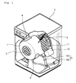
Fig. 1 is a perspective view of a drum type washing
machine where a damper according to a first embodiment of the
present invention is employed;
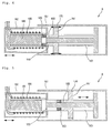
Fig. 2 is a sectional view of the damper depicted in
Fig. 1;
Fig. 3 is a sectional view taken along the line A-A'
of Fig. 2;
Fig. 4 is a sectional view of a damper according to a
first embodiment, illustrating a damping operation for
attenuating transient vibration of a drum when a washing machine
is in an initial dewatering operation;
Fig. 5 is a sectional view of a damper according to a
first embodiment, illustrating a damping operation for
attenuating relatively small vibration of a drum when a washing
machine is in a steady dewatering operation;
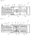
Fig. 6 is a sectional view of a damper according to a
second embodiment of the present invention;
Fig. 7 is a sectional view of a damper according to a
second embodiment, illustrating a damping operation for
attenuating transient vibration of a drum when a washing machine
is in an initial dewatering operation;
Fig. 8 is a sectional view of a damper according to a
second embodiment, illustrating a damping operation for
attenuating relatively small vibration of a drum when a washing
machine is in a steady dewatering operation;
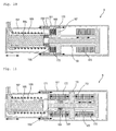
Fig. 9 is a sectional view of a damper according to a
third embodiment of the present invention;
Fig. 10 is a sectional view of a damper according to a
third embodiment, illustrating a damping operation for
attenuating transient vibration of a drum when a washing machine
is in an initial dewatering operation;
Fig. 11 is a sectional view of a damper according to a
third embodiment, illustrating a damping operation for
attenuating relatively small vibration of a drum when a washing
machine is in a steady dewatering operation;
Fig. 12 is a sectional view of a damper according to a
fourth embodiment of the present invention;
Fig. 13 is a graph illustrating a test result of the
fourth embodiment;
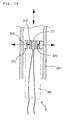
Fig. 14 is a sectional view of a damper according to a
fifth embodiment of the present invention;
Fig. 15 is a sectional view of a damper according to a
fifth embodiment, illustrating a damping operation for
attenuating transient vibration of a drum when a washing machine
is in an initial dewatering operation;
Fig. 16 is a sectional view of a damper according to a
fifth embodiment, illustrating a damping operation for
attenuating relatively small vibration of a drum when a washing
machine is in a steady dewatering operation;
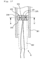
Fig. 17 is a sectional view of a damper according to a
sixth embodiment of the present invention;
Fig. 18 is a sectional view taken along the line B-B'
of Fig. 17;
Fig. 19 is a sectional view of a damper according to a
sixth embodiment, illustrating a damping operation for
attenuating transient vibration of a drum when a washing machine
is in an initial dewatering operation; and
Fig. 20 is a sectional view of a damper according to a
sixth embodiment, illustrating a damping operation for
attenuating relatively small vibration of a drum when a washing
machine is in a steady dewatering operation.
DETAILED DESCRIPTION OF THE INVENTION
Reference will now be made in detail to the preferred
embodiments of the present invention, examples of which are
illustrated in the accompanying drawings. Wherever possible, the
same reference numbers will be used throughout the drawings to
refer to the same or like parts.
In the embodiments of the present invention, a drum
type washing machine is exemplified. However, the present
invention is not limited to the drum type washing machine. The
present invention can be applied to a variety of devices
generating vibration as well as other types of the washing
machine.
First Embodiment
Fig. 1 shows a perspective view of a drum type washing
machine where a damper according to a first embodiment of the
present invention is employed.
As shown in the drawing, a drum type washing machine
includes a case 3, a tub 1 disposed in the case 3 to storing
water, a drum 2 disposed in the tub 1 to receive the laundry, and
a driving motor 10 disposed on a rear side of the tub 1 to rotate
the drum 2.
The operation of the drum type washing machine will be
described hereinafter.
Rotational force of the driving motor 10 is
transmitted to the drum 2 via a belt 11. When the drum 2 rotates,
the laundry loaded in the drum 2 rotates together with the drum 2.
At this point, since the drum 2 rotates with a relatively low RPM,
the laundry ascends by the rotation of the drum and drops by a
gravity to collide with the water contained in the tub 1. By
colliding force between the laundry and the water, dirts and
contaminants stuck on the laundry are removed. Although the
driving force of the driving motor 10 is transmitted to the drum
via the belt 11 in this embodiment, the driving motor 10 may be
designed to directly rotate the drum 2. Even when the driving
motor is directly connected to the drum 2, it will be apparent
that the vibration is generated by the rotation of the drum 2.
In addition, the washing machine further includes a
weight 4 disposed on an outer circumference of the tub 1 to
correct the center of gravity of the tube 1 in all directions, a
spring 5 having opposite ends respectively connected to the case
3 and the tub 1 to alleviate vibration generated from both the
tub 1 and the drum 2, and a damper 8 having opposite ends
respectively connected to the case 3 and the tub 1 to attenuate
vibration generated in the tub 1.
The weight 4 is designed to correct the center of
gravity of the tub 1 to radically alleviate the vibration that
may be generated by the eccentric center of gravity of the tub 1.
The vibration generated by the operation of the tub 1
is first absorbed by the spring 5 and is then attenuated by the
damper 8. As a result, the vibration generated by the operation
of the tube 1 can be quickly removed.
In detail, the damper includes a cylinder 161 of which
one end is fixed to the tub 1, and a rod 162 of which one end is
fixed to the case 3 and inserted into the cylinder 161. Of
course, the damper 8 may be constructed such that the rod 162 is
connected to the tub 1 and the cylinder is connected to the case
3.
Describing operation of the damper 8, a damping pad is
inserted between the rod 162 and the cylinder 161 inserted into
the rod 162, and is in contact with an inner circumference of the
cylinder 161. When vibration generated from the tub 1 is
transferred to the cylinder 161 so that the cylinder 161 and the
rod 162 are displaced different with each other in the length
direction, damping is performed by a frictional force between the
inner circumference of the cylinder 161 and the damping pad (see
numeral 170 of Fig. 2).
Shape and structure of the damper will be described
hereinafter.
Fig. 2 shows a sectional view of the damper according
to a first embodiment of the present invention, and Fig. 3 shows
a sectional view taken along the line A-A' of Fig. 2.
As shown in the drawings, the damper 8 comprises a
hollow cylinder 161, a rod 162 of which one end is inserted in
the cylinder 161, a sliding rod 163 integrally formed on an end
of the rod 162, a coil 166 disposed in the rod 162, an
electromagnet 165 selectively magnetized by the coil 166, a pad
holder 167 slidably disposed around an outer circumference of the
sliding rod 163 and coupled on a proximal end of the rod 161 when
the electromagnet 165 is magnetized, and a damping pad 170
disposed around an outer circumference of the pad holder 167 to
generate damping force by a friction with an inner circumference
of the cylinder 161.
The pad holder 167 is provided with protruded member
168 for allowing the pad holder 167 to move toward the rod 162 by
attractive force between the electromagnet 165 and a magnetic
member 169. The magnetic member 169 is fixed on the protruded
member 168 to be attracted to the electromagnet 165. The
protruded member 168 is formed to be identical in a shape to the
magnetic member 169. The magnetic member 169 is formed of
semicircular magnets or a plurality of circular arc-shape magnets
spaced from each other at a predetermined distance. The
magnetic member 169 may be formed of a material such as iron that
can be attracted and repulsed by the electromagnet 165.
The rod 162 is provided at a proximal end with a
plurality of insertion holes 159 formed in a shape identical to
those of the protruded member 168 and the magnetic member 169 so
that the magnetic member 169 can be attracted by and attached on
the electromagnet 165. The sliding rod 163 is provided at an
outer circumference with a plurality of guide grooves 164 in the
formed of a spline shaft so that the pad holder 167 can be
smoothly moved to the proximal end of the rod 162 by attractive
force of the electromagnet 165.
The electromagnet 165, the magnetic member 169, and
the protruded member 168 are all provided to move the pad holder
167 to a predetermined location, allowing a user to selectively
operate the pad holder 167.
The operation of the above-described damper will be
described hereinafter.
In an initial dewatering operation where a dewatering
RPM is lower than a predetermined dewatering RPM, the damper 8
should generate relatively large damping force so that transient
vibration of the drum 2 can be attenuated. In a steady
dewatering operation where a dewatering RPM is higher than the
predetermined dewatering RPM, since relatively small vibration is
generated, the damping force generated by the damper 8 should be
minimized so that vibration transmitted from the damper 8 to the
case 3 can be attenuated. By this operation, the vibration and
noise can be reduced in the washing machine.
In the initial dewatering operation generating the
transient vibration, electric power is applied to the coil 166 to
generate magnetic field on the electromagnet 165. By the
magnetic field, attractive force is generated between the
electromagnet 165 and the magnetic member 169. As a result, the
magnetic member 169 is attached on a proximal end of the
electromagnet 165 through the insertion holes 159. That is, the
pad holder 167 and the rod 162 are operated in a state where they
are integrated as a single body. That is, the operation of the
rod 162 is directly related with the operation of the damping pad
170, performing the damping operation using frictional force.
In addition, in the steady dewatering operation, no
electric power is applied to the coil 166. At this point, since
the rod 162 is separated from the pad holder 167, no frictional
force is generated between the damping pad 170 and the inner
circumference of the cylinder 161.
Fig. 4 illustrates a damping operation for attenuating
transient vibration of the drum when the washing machine is in
the initial dewatering operation, while Fig. 5 illustrates a
damping operation for attenuating relatively small vibration of a
drum when a washing machine is in a steady dewatering operation.
Referring first to Fig. 4, the damper 8 is designed to
generate high frictional damping force in the initial dewatering
operation where the transient vibration is generated. That is,
after the electric power is applied to the electromagnet 165, the
drum 2 is spun to remove water from the laundry. In the initial
dewatering operation, the transient vibration is generated on the
drum 2 due to the laundry eccentrically distributed. By the
transient vibration of the drum 2, the rod 162 linearly moves and
the pad holder 167 moves to the proximal end of the rod 162 along
the guide grooves 164 formed on the outer circumference of the
sliding rod 163 by the attractive force between the electromagnet
165 disposed in the rod 162 and the magnetic member 169 fixed on
the protruded member 168 of the pad holder 167. Since the
magnetic member 169 is inserted into the rod 162 through the
insertion holes 159 and the electromagnet 165 and the magnetic
member 169 are attached to each other, the pad holder 167 is to
be fixed on the proximal end of the rod 162.
In a state where the pad holder 167 is fixed on the
proximal end of the rod 162, damping force enough to attenuate
the transient vibration of the drum 2 that is generated in the
initial dewatering operation can be obtained by frictional force
generated between the damping pad 170 and the inner circumference
of the cylinder 161 as the rod 162 linearly moves. Here, it
should be noted that the operation of the rod 162 is relative to
the operation of the cylinder 161.
Referring to Fig. 5, in the steady dewatering
operation where the drum stably spins, relatively small vibration
is generated on the drum 2. Therefore, the electric power being
applied to the electromagnet 165 is cut off to degauss the
electromagnet 165. As a result, the magnetic member 169 is
separated from the electromagnet 165, whereby the pad holder 167
is released from the rod 162 and is fixed on a location of the
cylinder 161.
In this state, the sliding rod 163 reciprocally moves
along an inner circumference of the pad holder 167. That is, a
location of the damping pad 170, the pad holder 167 which is
integrated with the damping pad 170, the protruded member 168 and
the magnetic member 169, with respect to the cylinder 161 is
fixed. In addition, the protruded member 168 and the magnetic
member 169 can slide while being guided by the guide grooves 164
of the sliding rod 163. That is, as the slide rod 163
reciprocally moves along the inner circumference of the pad
holder 167, the small vibration of the drum 2 that is generated
in the steady dewatering operation can be attenuated.
To provide a friction reducing effect in the steady
dewatering operation, an additional damping member may be formed
between the sliding rod 163 and the pad holder 167. At this
point, in order to attenuate the relatively small vibration, a
damping constant of the damping member should be lower than that
of the damping pad 170.
Meanwhile, the drum 2 may conically rotate (rotate in
a cone-shape, while rocking from side to side and moving up and
down) when the laundry is eccentrically loaded in the drum 2.
The unstable rotation may cause conical vibration of the tub 20,
which is applied to the damper 8. At this point, the cylinder
161 and the rod 162 rotate relative to each other to create
torsion. As the result, the torsion is applied to the damper 8.
In the present invention, since the rotation of the sliding rod
163 may be suppressed by the protruded member 168 and the
magnetic member 169, the sliding rod 163 cannot freely rotate.
Furthermore, since the rotational force of the sliding rod 163 is
transmitted to the damping pad 170 through the pad holder 167,
the damping operation is realized by a frictional operation
between the inner circumference of the cylinder 161 and the
damping pad 170.
By the above-described operation, the vibration
generated in the washing machine can be stably attenuated. That
is, the damping force can be positively adjusted in response to
the operation of the washing machine (i.e., the initial
dewatering operation and the steady dewatering operation). That
is, the low vibration and low noise can be easily realized for
the washing machine. Here, the arrows on the Figs represent
operation states of operation portions.
Second Embodiment
Figs. 6, 7 and 8 illustrate a second embodiment of the
present invention. That is, Fig. 6 shows a sectional view of a
damper of the second embodiment of the present invention, Fig. 7
shows the damper of this embodiment, illustrating a damping
operation for attenuating transient vibration of a drum when a
washing machine is in an initial dewatering operation, and Fig. 8
shows a damper of this embodiment, illustrating a damping
operation for attenuating relatively small vibration of a drum
when a washing machine is in a steady dewatering operation.
In this embodiment, to further improve damping force
in the initial and/or steady dewatering operation, a second
damping pad 171 is further provided so that frictional force is
generated between the inner circumference of the cylinder 161 and
the outer circumference of the rod 162.
That is, in the initial dewatering operation where the
drum 2 is excessively vibrated, the damper of this embodiment is
designed such that the bigger damping force including the damping
force of the damping pad 170 fixed on the pad holder 167 can be
applied to the inner circumference of the cylinder 161. A second
damping pad 171 is further provided on the outer circumference of
the rod 162 so that, even in the steady dewatering operation
where relatively small vibration is incurred on the drum 2,
relatively small damping force in addition to the damping force
of the damping pad 170 fixed on the pad holder 170 can be exerted
to attenuate the vibration of the drum 2.
The operation of the second embodiment will be
described hereinafter.
In the initial dewatering operation where the
transient vibration is generated, electric power is applied to
the coil 166 so that attractive force is generated between the
electromagnet 165 and the magnetic member 169. As a result, the
pad holder 167 is fixed on the proximal end of the rod 162,
whereby, as the rod linearly moves, frictional force is generated
between the damping pad 170 and the inner circumference of the
cylinder 161 and between the second damping pad 171 and the inner
circumference of the cylinder 161, thereby attenuating the
transient vibration of the drum 2.
In the steady dewatering operation, the electric power
being applied to the coil 166 is cut off so that the pad holder
167 can be released from the rod 162. As the rod 162 linearly
moves, frictional force is generated between the sliding rod 163
and an inner circumference of the pad holder 167, realizing the
damping. At this point, the damping is further realized by
frictional force between the second damping pad 171 and the inner
circumference of the cylinder 161.
This embodiment provides the bigger damping force as a
whole as compared with the first embodiment. Here, the arrows on
the Figs represent operation states of operation portions.
Third Embodiment
Figs. 9, 10 and 11 illustrate a third embodiment of
the present invention. That is, Fig. 9 shows a sectional view of
a damper according to a third embodiment of the present invention,
Fig. 10 shows a damper of this embodiment, illustrating a damping
operation for attenuating transient vibration of a drum when a
washing machine is in an initial dewatering operation, and Fig.
11 shows the damper of this embodiment, illustrating a damping
operation for attenuating relatively small vibration of a drum
when a washing machine is in a steady dewatering operation.
In this embodiment, to completely separate the pad
holder 167 from the rod 162 using elastic force when the
electromagnet is degaussed and to quickly attenuate small
vibration of the drum in the steady dewatering operation, an
elastic member such as a sponge 172 is further formed on both
sides of the pad holder 167.
The operation of the third embodiment will be
described hereinafter.
The damping operation in the initial dewatering
operation where the drum 2 is excessively vibrated is identical
to the second embodiment, the detailed description of which will
be omitted herein.
In the steady dewatering operation, the electric power
being applied to the coil 166 is cut off to remove attractive
force between the electromagnet 165 and the magnetic member 169.
As a result, the pad holder 167 fixed on the proximal end of the
rod 162 is easily separated from the rod 162 by elastic force of
the sponge 172.
When vibration is generated, as the rod 162 linearly
moves, frictional force occurs between the sliding rod 163 and an
inner circumference of the pad holder 167, realizing the damping.
At this point, the damping is further realized by frictional
force between the second damping pad 171 and the inner
circumference of the cylinder 161. In addition, by the repeated
compressing/expanding operation of the sponge 172, the sliding
rod 166 linearly moves along the inner circumference of the pad
holder 167, thereby performing the damping. That is, since the
damping is realized at three locations, the damping effect can be
more improved (see Fig. 11).
Fourth Embodiment
Fig. 12 shows a sectional view of a damper according
to a fourth embodiment of the present invention.
The fourth embodiment is identical to the third
embodiment except that a spring 174 is used as the elastic member.
To support the spring 174, the rod 162 is provided at the
proximal end with a stepped portion 158. Since other parts of
the fourth embodiment are identical to those of the third
embodiment, the detailed description thereof will be omitted
herein.
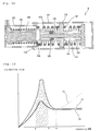
Fig. 13 shows a graph illustrating a test result of
the fourth embodiment.
In the graph, a horizontal axis indicates a dewatering
RPM and a vertical axis indicates transmitting force for
transmitting vibration that in not attenuated by the damper to
the case. A line 40 indicates a case of the conventional one-stage
damper, a line 20 indicates a case of the conventional two-stage
damper and a line 30 indicates a case of a damper of this
embodiment. As shown in the drawing, the damper of this
embodiment reduces the transmitting force in the steady
dewatering section (over ω) as well as in the transient
vibration section (between "a" and "b"),
Fifth Embodiment
Figs. 14, 15 and 16 show a damper according to a fifth
embodiment of the present invention.
Referring first to Fig. 14, a damper 8 of this
embodiment includes a movable part 270 expandable in a
longitudinal direction by electric power, a hollow rod 262 for
receiving the movable part 270, the rod 262 being connected to a
case (see 3 of Fig. 1), a hollow cylinder 261 for receiving the
rod 262, the cylinder 261 being connected to a tube (see 1 of
Fig.1), a sliding rod 273 inserted in the rod 262 to be linearly
movable in response to a length variation of the movable part 270,
a stopper end 276 formed on an inserted end of the rod 173, a pad
holder 275 disposed on an outer circumference of the sliding rod
273, and a damping pad 274 disposed on the pad holder 175 to
generate damping force using frictional force generated between
the damping pad and an inner circumference of the cylinder 161.
The movable part 270 includes a heater 271 generating
heat when electric power is applied and a thermal expanding
member 272 expanding in the longitudinal direction by the heat
generated by the heater 271. The pad holder 275 is movable
between the rod 262 and the stopper end 276. While the pad
holder 275 is pushed and moved by the rod 262 and the stopper end
276, a frictional force is generated by the pad holder 275
between the inner circumference of the cylinder 261 and the
damping pad 274.
The operation of this embodiment will be described
hereinafter.
When electric power is applied to the movable part 270,
a length of the thermal expanding member 272 is increased by heat
generated by the heater, as a result of which a predetermined gap
is defined between the rod 262 and the stopper end 276. The pad
holder 275 is movable in the gap. Therefore, even when outer
vibration is applied, the pad holder 275 is not moved but fixed
in the cylinder 261, not generating damping force.
However, when electric power is not applied, the
thermal expanding member 272 is contracted so as to be fixed by
the rod 162 and the stopper end 176. Therefore, when external
vibration is applied, the pad holder 275 moves together with the
rod 262 and the damping is realized by frictional force generated
between the damping pad 274 and the inner circumference of the
cylinder 261.
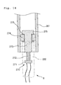
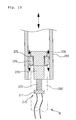
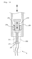
Fig. 15 shows the damper of this embodiment,
illustrating a damping operation for attenuating transient
vibration of a drum when a washing machine is in an initial
dewatering operation, and Fig. 16 shows the damper of this
embodiment, illustrating a damping operation for attenuating
relatively small vibration of a drum when a washing machine is in
a steady dewatering operation.
Referring first to Fig. 15, in the initial dewatering
operation where the transient vibration is generated on the drum
2, electric power is cut off to contract the thermal expanding
member 272. As a result, the sliding rod 273 moves to the
inserted end of the rod 262 and the pad holder 275 is fixed
between the inserted end and the stopper end 276. In a state
where the pad holder 275 is fixed, relatively large vibration
generated on the drum 2 in the initial dewatering operation can
be effectively attenuated by frictional force generated by
relative motion between the cylinder 261 and the damping pad 274.
It may be possible an additional damping pad is
further formed on an inserted outer circumference of the rod 262
to further improve damping force.
Referring to Fig. 16, in the steady dewatering
operation, electric power is applied to longitudinally expand the
thermal expanding member 272 using heat generated by the heater
271. When the thermal expanding member 272 expands, the sling
rod 273 is linearly pushed by a predetermined length, and the pad
holder 275 is to freely move along the sliding rod 273. That is,
in a state where the damping pad 274 fixed on the pad holder 275
contacts the inner circumference of the cylinder 261, the pad
holder 275 is movable between the inserted end of the rod 262 and
the stopper end 276.
In this state, when the cylinder 261 or the rod 262
moved in the longitudinal direction, the damping pad 274 moves
together with the cylinder 261, thereby not generating frictional
force. However, the damping is realized by relatively small
damping force generated between the inner circumference of the
pad holder 265 and the outer circumference of the rod 273.
Therefore, the relatively small vibration of the drum is
attenuated.
When the relatively small vibration of the drum is
higher than a predetermined level, an additional damping pad may
be further provided on the outer circumference of the rod 262 so
that enough frictional force is generated between the damping pad
and the inner circumference of the cylinder 261.
In addition, by adjusting the expansion of the thermal
expanding member 272, it is possible to set a start point of the
damping realized by the damping pad 274. This provides an
advantage of easily controlling the damper.
Sixth Embodiment
Figs. 17 to 20 show a sixth embodiment of the present
invention.
Fig. 17 shows a sectional view of a damper according
to a sixth embodiment of the present invention, and Fig. 18 is a
sectional view taken along the line B-B of Fig. 18.
As shown in the drawings, a damper 8 of this
embodiment includes a hollow cylinder 361 connected to the tub 1,
a rod 362 having a first end connected to a case 3 and a second
end inserted in the cylinder 361, a movable part 370 expandable
in a lateral direction by electric power, the movable part 370
being mounted on the second end of the rod 362, pad holders 373
expanding and contracting in accordance with a width variation of
the movable part 370, the pad holders 373 being mounted on both
sides of the movable part 370, and a damping pad 374 for applying
damping force in a radial direction of the cylinder 361 in
accordance with expansion/contraction of the pad holders 373, the
damping pads 374 being mounted on outer circumferences of the pad
holders 373.
The movable part 370 includes a heater 371 generating
heat when electric power is applied and a thermal expanding
member 372 expanding in the lateral direction by the heat
generated by the heater 371.
The pad holders 373 are formed in a semicircular-shape
so that they can expand and contract in response to the width
variation of the movable part 370. The pad holders 373 are
installed on both sides of the movable part 370 by fixing rods
375.
The damping pads 374 are formed in an identical shape
to those of the outer circumferences of the pad holders 373 so
that damping force can be applied in the radial direction of the
cylinder 361 as the pad holders 373 expand and contract.
Alternatively, the damping pad 374 may be formed in a single
cylindrical shape to enclose all of the pad holders 373.
The operation of this embodiment will be described
hereinafter.
Fig. 19 shows the damper of this embodiment,
illustrating a damping operation for attenuating transient
vibration of a drum when a washing machine is in an initial
dewatering operation, and Fig. 20 shows the damper of this
embodiment, illustrating a damping operation for attenuating
relatively small vibration of a drum when a washing machine is in
a steady dewatering operation.
Referring first to Fig. 19, electric power is applied
to the heater 371 and the thermal expanding member 372 is
expanded in the lateral direction by the heat generated by the
heater 371. As a result, the pad holders 373 are expanded in the
radial direction of the cylinder 361. Accordingly, relatively
large frictional force is generated between the damping pads 374
and the inner circumference of the cylinder 361. Therefore, in
the initial dewatering operation where the drum is excessively
vibrated, the transient vibration can be quickly attenuated by
high damping force generated between the damping pad 374 and the
cylinder 361.
Referring to Fig. 20, in the steady dewatering
operation where the drum stably spins to generate relatively
small vibration, electric power is cut off to contract the
thermal expanding member 372 and the pad holders 373 are returned
to their initial positions. Relatively small frictional force is
generated between the damping pads 374 and the inner
circumference of the cylinder 361. As a result, the small
vibration generated on the drum 2 generated in the steady
dewatering operation can be quickly attenuated by the small
damping force generated by the damping pads 374 and the cylinder
361.
As described above, the present invention is designed
to effectively attenuate the vibration generated in the washing
machine, thereby realizing the low vibration/low noise washing
machine. Also, the present invention is designed to positively
control the operation of the washing machine in response to a
current operation state of the washing machine, making it
possible to stably operate the washing machine.
In addition, since damping force of the washing
machine can be adjusted in response to a preset condition set by
the user, the vibration of the washing machine can be properly
attenuated regardless of its current processing cycle.
In conclusion, the damper of the present invention
allows the washing machine to be stably operated with a low noise.
In addition, the damper is not easily damaged even when strong
vibration is transmitted from the movable part.
It will be apparent to those skilled in the art that
various modifications and variations can be made in the present
invention. Thus, it is intended that the present invention covers
the modifications and variations of this invention provided they
come within the scope of the appended claims and their
equivalents.