EP1479642A2 - Load handling machine - Google Patents
Load handling machine Download PDFInfo
- Publication number
- EP1479642A2 EP1479642A2 EP04011521A EP04011521A EP1479642A2 EP 1479642 A2 EP1479642 A2 EP 1479642A2 EP 04011521 A EP04011521 A EP 04011521A EP 04011521 A EP04011521 A EP 04011521A EP 1479642 A2 EP1479642 A2 EP 1479642A2
- Authority
- EP
- European Patent Office
- Prior art keywords
- front frame
- machine
- arm
- frame part
- axle
- Prior art date
- Legal status (The legal status is an assumption and is not a legal conclusion. Google has not performed a legal analysis and makes no representation as to the accuracy of the status listed.)
- Withdrawn
Links
Images


Classifications
-
- B—PERFORMING OPERATIONS; TRANSPORTING
- B66—HOISTING; LIFTING; HAULING
- B66F—HOISTING, LIFTING, HAULING OR PUSHING, NOT OTHERWISE PROVIDED FOR, e.g. DEVICES WHICH APPLY A LIFTING OR PUSHING FORCE DIRECTLY TO THE SURFACE OF A LOAD
- B66F9/00—Devices for lifting or lowering bulky or heavy goods for loading or unloading purposes
- B66F9/06—Devices for lifting or lowering bulky or heavy goods for loading or unloading purposes movable, with their loads, on wheels or the like, e.g. fork-lift trucks
- B66F9/065—Devices for lifting or lowering bulky or heavy goods for loading or unloading purposes movable, with their loads, on wheels or the like, e.g. fork-lift trucks non-masted
-
- B—PERFORMING OPERATIONS; TRANSPORTING
- B60—VEHICLES IN GENERAL
- B60G—VEHICLE SUSPENSION ARRANGEMENTS
- B60G9/00—Resilient suspensions of a rigid axle or axle housing for two or more wheels
- B60G9/02—Resilient suspensions of a rigid axle or axle housing for two or more wheels the axle or housing being pivotally mounted on the vehicle, e.g. the pivotal axis being parallel to the longitudinal axis of the vehicle
-
- B—PERFORMING OPERATIONS; TRANSPORTING
- B62—LAND VEHICLES FOR TRAVELLING OTHERWISE THAN ON RAILS
- B62D—MOTOR VEHICLES; TRAILERS
- B62D21/00—Understructures, i.e. chassis frame on which a vehicle body may be mounted
- B62D21/02—Understructures, i.e. chassis frame on which a vehicle body may be mounted comprising longitudinally or transversely arranged frame members
-
- B—PERFORMING OPERATIONS; TRANSPORTING
- B66—HOISTING; LIFTING; HAULING
- B66F—HOISTING, LIFTING, HAULING OR PUSHING, NOT OTHERWISE PROVIDED FOR, e.g. DEVICES WHICH APPLY A LIFTING OR PUSHING FORCE DIRECTLY TO THE SURFACE OF A LOAD
- B66F9/00—Devices for lifting or lowering bulky or heavy goods for loading or unloading purposes
- B66F9/06—Devices for lifting or lowering bulky or heavy goods for loading or unloading purposes movable, with their loads, on wheels or the like, e.g. fork-lift trucks
- B66F9/065—Devices for lifting or lowering bulky or heavy goods for loading or unloading purposes movable, with their loads, on wheels or the like, e.g. fork-lift trucks non-masted
- B66F9/0655—Devices for lifting or lowering bulky or heavy goods for loading or unloading purposes movable, with their loads, on wheels or the like, e.g. fork-lift trucks non-masted with a telescopic boom
-
- E—FIXED CONSTRUCTIONS
- E02—HYDRAULIC ENGINEERING; FOUNDATIONS; SOIL SHIFTING
- E02F—DREDGING; SOIL-SHIFTING
- E02F3/00—Dredgers; Soil-shifting machines
- E02F3/04—Dredgers; Soil-shifting machines mechanically-driven
- E02F3/28—Dredgers; Soil-shifting machines mechanically-driven with digging tools mounted on a dipper- or bucket-arm, i.e. there is either one arm or a pair of arms, e.g. dippers, buckets
- E02F3/30—Dredgers; Soil-shifting machines mechanically-driven with digging tools mounted on a dipper- or bucket-arm, i.e. there is either one arm or a pair of arms, e.g. dippers, buckets with a dipper-arm pivoted on a cantilever beam, i.e. boom
- E02F3/306—Dredgers; Soil-shifting machines mechanically-driven with digging tools mounted on a dipper- or bucket-arm, i.e. there is either one arm or a pair of arms, e.g. dippers, buckets with a dipper-arm pivoted on a cantilever beam, i.e. boom with telescopic dipper-arm or boom
Definitions
- This invention relates to a load handling machine of the kind having a working arm which may be manipulated to lift and lower loads in or on a working implement such as a loading forks, provided at or adjacent an end of the arm.
- Such machines with varying geometries are known, but a common geometry is to provide an operator's cab at one side of the machine, and the working arm at the side of the cab, on or near a central axis of the machine.
- the working arm typically is mounted on a superstructure of the machine, at a position rearwardly of the operator's cab, and extends forwardly by the side of the cab, forwardly of a front of the superstructure.
- the arm is lifted and lowered by linear actuators, and commonly includes a plurality of telescopic sections, so that the load can not only be raised by the working arm, but moved towards and away from the superstructure, whilst the superstructure includes a ground engaging structure by means of which the machine may move on the ground to transport the load for example.
- a machine with an alternative geometry is disclosed in French specification FR-A-2761972.
- a machine has an articulated chassis to effect steering of the machine, but importantly, there is a working arm which has a plurality of pivotally connected sections with a base section mounted on a machine superstructure. Relative pivoting between working arm sections is achieved by a complex arrangement of linear actuators which "push and pull" between the arm sections, and create visibility problems.
- the pivotal connection between the base section of the arm and the superstructure is at a longitudinal position forwardly of the axis of rotation of the front wheels.
- the pivotal connection has to be raised up which can lead to much reduced visibility.
- the front axle may be rigidly fixed to the front frame part, or the front axle mounting may permit the axle to oscillate about a generally longitudinal axis which may be coincident with or slightly offset from a central longitudinal axis of the machine.
- rigidly fixed we mean that the front axle is not able to oscillate relative to the front frame part in response to ground conditions, although adjustment of the axle relative to the front frame part by an actuator may be possible for levelling purposes.
- the front axle is provided at or adjacent a front end of the front frame part such that the longitudinal axis of oscillation is located between tops and bottoms of the front frame members.
- the front frame members may be shaped at the front of the front frame part so that at least a portion of the front axle is located below the tops of the front frame members.
- the front frame part includes an end closure, which may also provide a part of the mounting.
- the front axle may include a pair of trunnions which extend from an axle body along a longitudinal axis, one of the trunnions being received in an opening in a transverse mounting member which extends between the front frame members, and the other trunnion being received in an axially coincident opening provided in the end closure.
- the rear frame may include a pair of side members which may be spaced apart at least over a substantial portion of their longitudinal extent wider than the front frame members, and may include upper and lower closure plates as required to increase the stiffness of the rear frame part.
- the rear axle may include a pair of trunnions which extend from an axle body along the axis of oscillation, one of the trunnions being received in an opening in a transverse mounting member which extends between the rear frame side members, and the other trunnion being received in an axially coincident opening provided in the end closure.
- an engine of the machine could be mounted on an opposite side of the working arm to the cab, preferably the engine is carried by the rear frame part behind the cab, so that the weight of the engine can usefully be employed as a counterweight.
- a cooling pack for providing cooling for the engine and/or for hydraulic fluid for the various actuators may be provided on the other side of the working arm to the cab, or behind the cab.
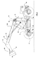
- the chassis 11 includes a generally elongate front frame part 22, and a rear frame part 23, rigidly connected together or integrally provided.
- the front frame part 22 includes a pair of generally elongate frame members 24, 25 which are each of upright plate-like configuration, which extend generally parallel to one another and have between them, a space 26.
- Each front frame member 24, 25 has a substantial thickness and thus strength, but to increase the torsional stiffness of the front frame part 22, top and bottom closure plates 27, 28 are provided, so that at least in regions of the front frame part 22 where the top and bottom closure plates 27, 28 are provided, the chassis 11 is of a box section configuration.
- the working arm 15 is located generally transversely centrally of the machine 10, but is mounted at a longitudinal position 62 between the cab 12 and the first transverse axis C on a mounting provided by the front frame part 22, close to the axle 16.
- the first arm part 64 is pivotally connected to a first end 68 of the second arm part 65, adjustment of the angle ⁇ between the first and second arm parts 64, 65 being achieved by the operation of one or a pair or more of first linear hydraulic actuators 70 which act between the first and second arm parts 64, 65, under the control of an operator.
- a fluid reservoir such as a fuel tank 86 may be accommodated beneath the transverse cab 12 support member 60.
- the rear side frame members 30, 30 of the rear frame part 23, adjacent to the front frame part 22, are shaped to provide a support surface 84 on which the first arm part 64 may rest when in a fully lowered condition.
- dampers would need to be provided to damp oscillations of the front 16 and/or rear axles 18, where oscillation is permitted, which dampers would extend between the axle body 40 and a part of a superstructure of the machine 10.
- the superstructure of the machine 10 may include body panels to conceal and mount working parts of the machine 10 including these not described above, such as a hydraulic pump, transmission, battery and so on, which may be accommodated where required.
- the front frame part 22 and the rear frame part 23 include top and bottom closure plates 58, 59 to add strength and stiffness, but in another example, one or both of the front and rear frame parts 22, 23 may be strengthened by another means.
- one or both of the frame parts 22, 23 may be of H cross section with internal strengthening plates, and/or partly strengthened by top and/or bottom closure plates, and partly by internal plates.
Landscapes
- Engineering & Computer Science (AREA)
- Structural Engineering (AREA)
- Transportation (AREA)
- Mechanical Engineering (AREA)
- Civil Engineering (AREA)
- Life Sciences & Earth Sciences (AREA)
- Geology (AREA)
- General Engineering & Computer Science (AREA)
- Mining & Mineral Resources (AREA)
- Chemical & Material Sciences (AREA)
- Combustion & Propulsion (AREA)
- Body Structure For Vehicles (AREA)
- Vehicle Body Suspensions (AREA)
Abstract
Description
Claims (19)
- A load handling machine (10) having a chassis (11) including an elongate front frame part (22) and a rear frame part (23), and an operator's cab (12) supported at least in part by the front frame (22) mounted to one side of a longitudinal machine axis (A), the front frame part (22) including a pair of frame members (24, 25) which extend generally parallel in a generally longitudinal direction of the machine (10), the front frame part (22) providing a mounting for a front axle (16) carrying a pair of steerable ground engaging wheels (19), each of which is rotatable about a first transverse front axle axis (C) when the wheels (19) are each in a straight ahead position, and the front frame part (22) providing a mounting for a working arm (15) between the pair of front frame members (24, 25) longitudinally between the first transverse axis (C) and the cab (12), the working arm (15) including first (64) and second (65) parts which are pivotally connected together so that the angle (α) between the first (64) and second (65) parts about a second transverse axis (E) is adjustable, the first arm part (64) being pivotally connected at or adjacent one end, to the front frame part (22) at a longitudinal position between the front axle axis (C) and the cab (12) for pivotal movement about a third transverse axis (F), and the first arm part (64) being connected at or adjacent an opposite end to a first end of the second arm part (65), and there being in use, a working implement (78) mounted at or adjacent to a second end of the second arm part (65).
- A machine (10) according to claim 1 wherein the mounting for the working arm (78) is provided on the front frame part (22) between the pair of front frame members (24, 25) longitudinally between the first transverse axis (C) and the cab (12).
- A machine (10) according to claim 1 or 2 wherein there is provided at least one first linear actuator (70) which acts between the first arm part (64) and the second arm part (65) and which is operable to adjust the angle (α)between the first and second arm parts about the second transverse axis (E).
- A machine (10) according to claim 3 wherein to move the first arm part (64) relative to the front frame part (22) about the first transverse axis (C), there is provided at least one second linear actuator (71) which acts between the front frame part (22) and the first working arm part (64), the second actuator (71) being pivotally connected to the front frame part (22) at a position located rearwardly of the mounting of the working arm (15) to the front frame part (64), and to the first arm part so as to extend rearwardly away from the first arm part (64) to its front frame mounting.
- A machine (10) according to claim 4 wherein the second actuator mounting to the front frame part (22) is positioned towards a rear or rearwardly of the cab (12).
- A machine (10) according to any one of the preceding claims wherein the second part (65) of the working arm (15) includes a plurality of relatively telescopic sections(75, 76).
- A machine (10) according to any one of the preceding claims wherein the front frame members (24, 25) each include a generally upright plate-like part, defining between them, a space (26).
- A machine (10) according to claim 7 wherein the mounting for the working arm (15) extends between and is secured to each of the plate-like parts.
- A machine (10) according to claim 7 or 8 wherein upper (34) and lower (35) closure plates are secured to the upright plate-like parts so that where provided, the front frame part (22) has a generally box section configuration.
- A machine (10) according to any one of the preceding claims wherein the front axle (16) is rigidly fixed to the front frame part (22).
- A machine (10) according to anyone of claims 1 to 9 wherein the front axle mounting permits the axle (16) to oscillate about a generally longitudinal axis which is coincident with or slightly offset from a central longitudinal axis (A) of the machine (10), and the front axle (16) is provided at or adjacent a front end of the front frame part (22) such that the longitudinal axis of oscillation is located between tops and bottoms of the front frame members 24, 25).
- A machine (10) according to any one of the preceding claims wherein the front frame part (22) includes a transverse support member (60) connected to and extending transversely from one of the front frame members (24, 25), to provide support for the cab (12).
- A machine (10) according to claim 12 wherein a fluid reservoir such as a fuel tank (86) is mounted generally beneath the transverse support member (60).
- A machine (10) according to any one of the preceding claims wherein the rear frame part (33) of the chassis (11) is integral with or securely and rigidly connected to the front frame part (22).
- A machine (10) according to any one of the preceding claims wherein the rear frame part (23) is shaped to provide an upper support surface on which the first part (64) of the arm (15) rests when in a fully lowered position.
- A machine (10) according to claim 14 or claim 15 wherein the rear frame part (23) includes a pair of side members (30, 31) which are spaced apart at least over a substantial portion of their longitudinal extent wider than the front frame members.
- A machine (10) according to claim 16 wherein the rear frame (23) includes upper and lower closer plates to increase the stiffness of the rear frame part.
- A machine (10) according to any one of the preceding claims wherein the rear frame (23) provides a mounting for a rear axle (18) which carries a pair of rear wheels (20); the rear wheels (20) being rotatable about a fourth generally transverse axis and the rear axle (20) mounting permitting the rear axle to oscillate about a generally longitudinal axis (D).
- A machine (10) according to any one of the preceding claims wherein an engine (82) of the machine (10) is carried by the rear frame part (23) behind the cab (12).
Applications Claiming Priority (2)
| Application Number | Priority Date | Filing Date | Title |
|---|---|---|---|
| GB0311520A GB2401851A (en) | 2003-05-20 | 2003-05-20 | Load handling machine with working arm between front axle and cab |
| GB0311520 | 2003-05-20 |
Publications (2)
| Publication Number | Publication Date |
|---|---|
| EP1479642A2 true EP1479642A2 (en) | 2004-11-24 |
| EP1479642A3 EP1479642A3 (en) | 2005-07-06 |
Family
ID=9958380
Family Applications (2)
| Application Number | Title | Priority Date | Filing Date |
|---|---|---|---|
| EP04011521A Withdrawn EP1479642A3 (en) | 2003-05-20 | 2004-05-14 | Load handling machine |
| EP04011520A Withdrawn EP1481939A3 (en) | 2003-05-20 | 2004-05-14 | Load handling machine |
Family Applications After (1)
| Application Number | Title | Priority Date | Filing Date |
|---|---|---|---|
| EP04011520A Withdrawn EP1481939A3 (en) | 2003-05-20 | 2004-05-14 | Load handling machine |
Country Status (3)
| Country | Link |
|---|---|
| US (2) | US20040240978A1 (en) |
| EP (2) | EP1479642A3 (en) |
| GB (2) | GB2401851A (en) |
Cited By (1)
| Publication number | Priority date | Publication date | Assignee | Title |
|---|---|---|---|---|
| EP3103758A1 (en) * | 2015-06-10 | 2016-12-14 | SKS Toijala Works Oy | Arrangement of the frame structure of a mobile reach machine |
Families Citing this family (2)
| Publication number | Priority date | Publication date | Assignee | Title |
|---|---|---|---|---|
| IT201900000607A1 (en) * | 2019-01-15 | 2020-07-15 | Manitou Italia Srl | Improved Equipment. |
| GB2582261B (en) | 2019-03-01 | 2023-06-21 | Bamford Excavators Ltd | Working machine |
Family Cites Families (28)
| Publication number | Priority date | Publication date | Assignee | Title |
|---|---|---|---|---|
| US1991577A (en) * | 1931-08-29 | 1935-02-19 | Baker Raulang Co | Running gear for vehicles |
| GB937675A (en) * | 1959-12-04 | 1963-09-25 | Linde Eismasch Ag | Improvements in or relating to fork lift trucks |
| US3281119A (en) * | 1964-04-10 | 1966-10-25 | Paul J Westfall | Fork lift with forward reach |
| DE1530613A1 (en) * | 1965-09-11 | 1969-08-21 | Daimler Benz Ag | Suspension using a rigid axle or crank axle control arm |
| GB1102963A (en) * | 1965-11-15 | 1968-02-14 | Richard Paine | Improvements relating to fork lift trucks |
| FR2124178B1 (en) * | 1971-02-04 | 1975-06-06 | Potain Sa | |
| CA954905A (en) * | 1971-10-29 | 1974-09-17 | Koehring Company | Vehicle having transverse leveling means |
| JPS6015509B2 (en) * | 1979-05-29 | 1985-04-19 | 日産自動車株式会社 | Forklift rear frame structure |
| JPS6383328A (en) * | 1986-09-29 | 1988-04-14 | Komatsu Ltd | Work equipment operating device |
| US4775288A (en) * | 1986-10-03 | 1988-10-04 | Dynamic Industries, Inc. | High-lift loader |
| US4729448A (en) * | 1987-01-30 | 1988-03-08 | Rockwell International Corporation | Offset trunnion bracket on steer drive axle |
| BE1003344A4 (en) * | 1990-01-24 | 1992-03-03 | Manitou Bf Sa | LIFT TRUCK WITH TELESCOPIC ARM. |
| GB2292931B (en) * | 1992-06-30 | 1996-10-02 | Caterpillar Inc | Material handling machine |
| IT228665Y1 (en) * | 1992-07-29 | 1998-05-07 | Dieci Flli | TELESCOPIC ARM FORKLIFT |
| DE4316364A1 (en) * | 1993-05-15 | 1994-11-17 | Faun Gmbh | Multi-purpose work vehicle |
| US5405237A (en) * | 1994-01-21 | 1995-04-11 | Deere & Company | Loader leveling linkage providing for alteration of its geometry for accommodating different implements |
| FI105329B (en) * | 1995-05-04 | 2000-07-31 | Ponsse Oy | Device for stabilization |
| US5873586A (en) * | 1996-03-04 | 1999-02-23 | Krimmell; John | Rocking beam suspension |
| FR2759662B1 (en) * | 1997-02-20 | 1999-04-23 | Fdi Sambron | LIFT TRUCK, LIFT TRUCK COMPRISING SUCH A CHASSIS, AND METHOD FOR MANUFACTURING SUCH A LIFT |
| FR2761972B1 (en) * | 1997-04-11 | 1999-07-23 | Modules Associes | IMPROVED SELF-PROPELLED TOOL HOLDER |
| US6406036B1 (en) * | 1997-05-16 | 2002-06-18 | Conception Et Developpement - Michelin S.A. | Vehicle suspension having active camber variation |
| US5944130A (en) * | 1997-11-04 | 1999-08-31 | Caterpillar Inc. | Trunnion mounted drive train arrangement |
| AU3686899A (en) * | 1998-07-01 | 2000-01-20 | Grove U.S. L.L.C. | Transportable crane |
| JP2000062486A (en) * | 1998-08-25 | 2000-02-29 | Seirei Ind Co Ltd | Front axle case support structure of farmwork machine |
| IT1304978B1 (en) * | 1998-09-10 | 2001-04-05 | Merlo Ind Metalmecc | VEHICLE USABLE AS LIFT AND AGRICULTURAL TRACTOR. |
| US6757958B1 (en) * | 2000-05-11 | 2004-07-06 | Jlg Omniquip, Inc. | Load handler with modular frame assembly |
| DE10219205A1 (en) * | 2002-04-29 | 2003-11-13 | Helmut Schmidt | Mobile universal working appliance especially for building sites has two-segment articulated arm folded flat on chassis when not in use, but with wide working area |
| ITTO20021068A1 (en) * | 2002-12-06 | 2004-06-07 | Fiat Kobelco Construction Machinery S P A | VEHICLE ON WHEELS WITH AN OSCILLATING AXLE AROUND A LONGITUDINAL AXIS. |
-
2003
- 2003-05-20 GB GB0311520A patent/GB2401851A/en not_active Withdrawn
-
2004
- 2004-05-14 EP EP04011521A patent/EP1479642A3/en not_active Withdrawn
- 2004-05-14 EP EP04011520A patent/EP1481939A3/en not_active Withdrawn
- 2004-05-18 US US10/847,816 patent/US20040240978A1/en not_active Abandoned
- 2004-05-18 US US10/847,815 patent/US20040262069A1/en not_active Abandoned
- 2004-05-19 GB GB0411098A patent/GB2401841B/en not_active Expired - Lifetime
Cited By (1)
| Publication number | Priority date | Publication date | Assignee | Title |
|---|---|---|---|---|
| EP3103758A1 (en) * | 2015-06-10 | 2016-12-14 | SKS Toijala Works Oy | Arrangement of the frame structure of a mobile reach machine |
Also Published As
| Publication number | Publication date |
|---|---|
| GB2401841A (en) | 2004-11-24 |
| EP1481939A3 (en) | 2005-07-06 |
| US20040262069A1 (en) | 2004-12-30 |
| EP1479642A3 (en) | 2005-07-06 |
| GB0311520D0 (en) | 2003-06-25 |
| US20040240978A1 (en) | 2004-12-02 |
| GB2401851A (en) | 2004-11-24 |
| EP1481939A2 (en) | 2004-12-01 |
| GB2401841B (en) | 2006-06-14 |
| GB0411098D0 (en) | 2004-06-23 |
Similar Documents
| Publication | Publication Date | Title |
|---|---|---|
| US6752403B2 (en) | Working apparatus | |
| EP1559837B1 (en) | Skid steer loader | |
| US6796762B2 (en) | Boom and linkage mechanism for skid-steer loader | |
| US6729830B2 (en) | Wheeled work machine and frame assembly | |
| RU2487018C2 (en) | Stabiliser system for wheel axle suspension, and stabiliser | |
| US4431363A (en) | Articulated material handling machine | |
| US4071090A (en) | Motorgrader implement mounting arrangement | |
| EP1479642A2 (en) | Load handling machine | |
| AU726297B2 (en) | Frame assembly for a construction machine | |
| US6957705B2 (en) | Loader linkage | |
| US10696114B2 (en) | Utility vehicle | |
| US20030070861A1 (en) | Wheeled work machine and frame assembly having a flat radiator | |
| EP0859888B1 (en) | Frame assembly for an articulated construction vehicle | |
| EP1154081B1 (en) | A machine having a working arm | |
| US6439827B1 (en) | Load handling vehicle | |
| CN116635591A (en) | Work machine | |
| GB2368573A (en) | A machine with working arm and having inclined tilt levers | |
| US20030070328A1 (en) | Frame assembly for a wheeled work machine | |
| US4810161A (en) | Reach attachment | |
| JPH0939645A (en) | Self-propelled crane | |
| EP0857241A1 (en) | Hitch assembly for the front frame of an articulated construction machine | |
| CA2463319C (en) | Wheeled work machine | |
| US3921833A (en) | Material lifting and transporting vehicle | |
| CA1109098A (en) | Suspension assembly for off-road vehicle | |
| JPH10248306A (en) | Management machine |
Legal Events
| Date | Code | Title | Description |
|---|---|---|---|
| PUAI | Public reference made under article 153(3) epc to a published international application that has entered the european phase |
Free format text: ORIGINAL CODE: 0009012 |
|
| AK | Designated contracting states |
Kind code of ref document: A2 Designated state(s): AT BE BG CH CY CZ DE DK EE ES FI FR GB GR HU IE IT LI LU MC NL PL PT RO SE SI SK TR |
|
| AX | Request for extension of the european patent |
Extension state: AL HR LT LV MK |
|
| PUAL | Search report despatched |
Free format text: ORIGINAL CODE: 0009013 |
|
| AK | Designated contracting states |
Kind code of ref document: A3 Designated state(s): AT BE BG CH CY CZ DE DK EE ES FI FR GB GR HU IE IT LI LU MC NL PL PT RO SE SI SK TR |
|
| AX | Request for extension of the european patent |
Extension state: AL HR LT LV MK |
|
| 17P | Request for examination filed |
Effective date: 20051230 |
|
| AKX | Designation fees paid |
Designated state(s): AT BE BG CH CY CZ DE DK EE ES FI FR GB GR HU IE IT LI LU MC NL PL PT RO SE SI SK TR |
|
| STAA | Information on the status of an ep patent application or granted ep patent |
Free format text: STATUS: THE APPLICATION IS DEEMED TO BE WITHDRAWN |
|
| 18D | Application deemed to be withdrawn |
Effective date: 20061201 |