EP1479639A1 - Escalator with high-speed inclined section - Google Patents
Escalator with high-speed inclined section Download PDFInfo
- Publication number
- EP1479639A1 EP1479639A1 EP03700595A EP03700595A EP1479639A1 EP 1479639 A1 EP1479639 A1 EP 1479639A1 EP 03700595 A EP03700595 A EP 03700595A EP 03700595 A EP03700595 A EP 03700595A EP 1479639 A1 EP1479639 A1 EP 1479639A1
- Authority
- EP
- European Patent Office
- Prior art keywords
- steps
- speed
- link
- inclined portion
- escalator
- Prior art date
- Legal status (The legal status is an assumption and is not a legal conclusion. Google has not performed a legal analysis and makes no representation as to the accuracy of the status listed.)
- Withdrawn
Links
Images



Classifications
-
- B—PERFORMING OPERATIONS; TRANSPORTING
- B66—HOISTING; LIFTING; HAULING
- B66B—ELEVATORS; ESCALATORS OR MOVING WALKWAYS
- B66B21/00—Kinds or types of escalators or moving walkways
- B66B21/02—Escalators
- B66B21/025—Escalators of variable speed type
Definitions
- the present invention relates to a high-speed inclined portion escalator in which a traveling speed of steps in an intermediate inclined portion is higher than a traveling speed of the steps in an upper landing portion and a lower landing portion.
- high-speed inclined portion escalators have been proposed in which it is possible for the amount of time spent riding the escalator to be shortened by operating at low speed in upper and lower landing portions where the passengers get on and of f , operating to accelerate and decelerate in an upper curved portion and a lower curved portion, and operating at high speed in an intermediate inclined portion.
- a high-speed inclined portion escalator of this kind is disclosed in Japanese Patent Laid-Open No. SHO 51-116586 (Gazette), for example.
- a speed ratio (a speed change ratio) between a traveling speed of the steps in the upper landing portion and the lower landing portion and a traveling speed of the steps in the intermediate inclined portion should be set. If the speed change ratio is too small, effects such as shortening of traveling time cannot be expected. If the speed change ratio is too large, the difference in level between steps becomes large in the intermediate inclined portion, making it difficult for passengers to walk on the steps in emergencies, etc.
- the present invention aims to solve the above problems and an object of the present invention is to provide a high-speed inclined portion escalator capable of ensuring an appropriate difference in step level in an intermediate inclined portion.
- a high-speed inclined portion escalator including: a cyclic path having an upper landing portion, a lower landing portion, and an intermediate inclined portion positioned between the upper landing portion and the lower landing portion; and a plurality of steps linked endlessly and moved cyclically along the cyclic path, wherein a speed ratio of a traveling speed of the steps in the intermediate inclined portion to a traveling speed of the steps in the upper landing portion and the lower landing portion is less than or equal to 2.0.
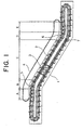
- Figure 1 is a schematic side elevation showing a high-speed inclined portion escalator according to Embodiment 1 of the present invention.
- a plurality of steps 2 linked endlessly are disposed in a main frame 1.
- the steps 2 are driven by a drive unit (a step driving means) 3, and are moved cyclically.
- a pair of the handrails 4 are disposed upright on an upper portion of the main frame 1.
- the handrails 4 are disposed on both sides in a width direction of the steps 2.
- Main tracks 5 forming a cyclic path for the steps 2, trailing tracks 6 for controlling the attitude of the steps 2, and auxiliary tracks 7 for changing a pitch between adjacent steps 2 are disposed on the main frame 1.
- the cyclic path for the steps 2 has: a forward section, a return section, an upper inversion portion, and a lower inversion portion.
- the forward section of the cyclic path has: an upper landing portion (an upper horizontal portion) A, an upper curved portion B, an intermediate inclined portion (a constant inclination portion) C, a lower curved portion D, and a lower landing portion (a lower horizontal portion) E.
- FIG. 2 is a side elevation showing a vicinity of the upper landing portion A and the upper curved portion B in Figure 1 enlarged.
- the steps 2 have: a tread 8 for carrying passengers; a curved riser 9 formed on one edge in a depth direction of the tread 8; a step link roller shaft 10; a pair of step link rollers 11 that are rotatable around the step link roller shaft 10; a trailing roller shaft 12; and a pair of trailing rollers 13 that are rotatable around the trailing roller shaft 12.
- the step link rollers 11 roll along the main tracks 5.
- the trailing rollers 13 roll along the trailing tracks 6.
- the step link roller shafts 10 of mutually-adjacent steps 2 are linked to each other by a pair of linking mechanisms (folding links) 14.
- Each of the linking mechanisms 14 has first to fifth links 15 to 19.
- a first end portion of the first link 15 is linked pivotably to the step link roller shaft 10.
- a second end portion of the first link 15 is linked pivotably to an intermediate portion of the third link 17 by means of a shaft 20.
- a first end portion of the second link 16 is linked pivotably to the step link roller shaft 10 of the adjacent step 2.
- a second end portion of the second link 16 is linked pivotably by means of the shaft 20 to the intermediate portion of the third link 17.
- a first end portion of the fourth link 18 is connected pivotably to an intermediate portion of the first link 15.
- a first end portion of the fifth link 19 is connected pivotably to an intermediate portion of the second link 16.
- Second end portions of the fourth and fifth links 18 and 19 are linked to a first end portion of the third link 17 by means of a sliding shaft 21.
- a guiding groove 17a for guiding sliding of the sliding shaft 21 in the longitudinal direction of the third link 17 is disposed on the first end portion of the third link 17.
- a rotatable auxiliary roller 22 is disposed on a second end portion of the'third link 17. The auxiliary roller 22 is guided by the auxiliary tracks 7.
- a pitch between the step link roller shafts 10, and thus a relative pitch between adjacent steps 2 is changed by the auxiliary rollers 22 being guided by the auxiliary tracks 7 to change the shape of the linking mechanisms 14 so as to fold and unfold.
- tracks of the auxiliary tracks 7 are designed such that the relative pitch between adjacent steps 2 changes.
- the speed of the steps 2 is changed by changing the pitch between the step link roller shafts 10 of adjacent steps 2.
- the pitch between the step link roller shafts 10 is minimized in the upper landing portion A and the lower landing portion E where the passengers get on and off, and the steps 2 move at low speed.
- the pitch between the step link roller shafts 10 is maximized in the intermediate inclined portion C, and the steps 2 move at high speed.
- the pitch between the step link roller shafts 10 changes in the upper curved portion B and the lower curved portion D, and the steps 2 accelerate or decelerate.
- the first, second, fourth, and fifth links 15, 16, 18, and 19 constitute a four-link "pantograph" linking mechanism, enabling the angle formed by the first and second links 15 and 16 to be enlarged and reduced with the third link 17 as an axis of symmetry.
- the pitch between the step link roller shafts 10 linked by the first and second links 15 and 16 can be changed.
- the pitch between the step link roller shafts 10 of adjacent steps 2 is minimized. From this state, when the distance between the main tracks 5 and the auxiliary tracks 7 is reduced, the linking mechanisms 14 operate in a similar manner to the operation of the frame of an umbrella as the umbrella is being opened out, increasing the pitch between the step link roller shafts 10 of the adjacent steps 2.
- the distance between the main tracks 5 and the auxiliary tracks 7 is smallest in the intermediate inclined portion C in Figure 1, and the pitch between the step link roller shafts 10 of the adjacent steps 2 is maximized. Consequently, the speed of the steps 2 is maximized in this region.
- the first and second links 15 and 16 are disposed almost in a straight line.
- Figure 3 is an explanatory diagram showing an example of an arrangement of steps 2 in the intermediate inclined portion C in Figure 1.
- a speed change ratio is 1.5
- the depth dimension of the treads 8 is approximately 400 mm
- an angle of inclination of the intermediate inclined portion C is 30 degrees (30°). This depth dimension and this angle of inclination are similar to those of a standard escalator.
- the speed change ratio is increased, the pitch between the step link roller shafts 10 in the intermediate inclined portion C is increased, and the difference in level between the steps 2 can also be considered to be increased.
- the difference in level between the steps 2 is approximately 300 mm (being approximately 200 mm in a standard escalator).
- This difference in level is a dimension enabling passengers to walk on the steps 2 easily. Consequently, if the escalator stops in an emergency, etc., the passengers can move smoothly by walking on the steps 2. Furthermore, if the speed change ratio is 1.5, the time required to reach an adjacent floor is shortened by approximately 30 percent (30%) compared to a normal escalator that does not change speed, enabling the effects of changing the speed of the steps to be achieved satisfactorily.
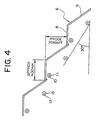
- Figure 4 is an explanatory diagram showing another example of an arrangement of steps 2 in the intermediate inclined portion C in Figure 1.
- a speed change ratio is 2.0
- the depth dimension of the treads 8 is approximately 400 mm
- an angle of inclination of the intermediate inclined portion C is 30 degrees (30°).
- the speed change ratio is 2.0
- the difference in level between the steps 2 is approximately 400 mm. This difference in level can be considered a general limit for passengers to be able to walk on the steps 2.
- the speed change ratio it is preferable for the speed change ratio to be set to less than or equal to 2.0. Furthermore, if the speed change ratio is set to less than or equal to 1.8, the difference in level can be reduced to enable passengers with short legs such as children, etc., also to walk on the steps 2 easily. In particular, if the speed change ratio is 1.5, as shown in Figure 3, all passengers can walk on the steps 2 smoothly.
- time-shortening effects are achieved if the speed change ratio is larger than 1.0, but in reality, it is preferable for the ratio to be greater than or equal to 1.2. Specifically, if the speed change ratio is greater than or equal to 1.2, most passengers are able to feel the effects of the shortening of the traveling time because the traveling time is shortened by greater than or equal to approximately 20 percent (20%).
- Figure 5 is a side elevation showing part of a high-speed inclined portion escalator according to Embodiment 2 of the present invention
- Figure 6 is a structural diagram showing a linking mechanism from Figure 5 dismantled.
- main tracks 31, trailing tracks 32, and auxiliary tracks 33 are disposed on a main frame (not shown).
- a plurality of steps 34 linked endlessly are disposed on the main frame.
- Each step 34 has: a tread 35 for carrying passengers; a curved riser 36 formed on one edge in a depth direction of the tread 35; a step link roller shaft 37; a pair of step link rollers 38 that are rotatable around the step link roller shaft 37; a trailing roller shaft 39; and a pair of trailing rollers 40 that are rotatable around the trailing roller shaft 39.
- the step link rollers 38 roll along the main tracks 31.
- the trailing rollers 40 roll along the trailing tracks 32.
- the step link roller shafts 37 of mutually-adjacent steps 34 are linked to each other by a pair of linking mechanisms (folding links) 41.
- Each of the linking mechanisms 41 has: first and second links 42 and 43; and an auxiliary roller 44 that rolls along the auxiliary tracks 33.
- a first end portion of the first link 42 is linked pivotably to the step link roller shaft 37.
- the auxiliary roller 44 is rotatably mounted to a second end portion of the first link 42.
- a first end portion of the second link 43 is linked pivotably by means of a shaft 45 to an intermediate portion of the first link 42.
- a second end portion of the second link 43 is linked pivotably to the step link roller shaft 37 of the adjacent step 34.
- the first link 42 has: a straight first portion 42a linked to the step link roller shaft 37; and a straight second portion 42b to which the auxiliary roller 44 is mounted.
- the second portion 42b forms a predetermined angle relative to the first portion 42a.
- the first link 42 has a shape angled away from the second link 43.
- the first portion 42a and the second portion 42b may be an integrated body, or they may also be separate parts.
- the linking mechanisms 41 are folded and unfolded together with the movement of the steps 34 by changing the distance between the main tracks 31 and the auxiliary tracks 33 depending on position.
- the pitch between the steps 34 is varied to change the traveling speed of the steps 34.
- the number of joint portions (bearing portions) between the links is minimized, significantly reducing the influence of backlash and friction.
- the passengers can also move smoothly by walking on the steps 2 and the time required to reach an adjacent floor can also be shortened sufficiently by setting the speed change ratio within a range greater than or equal to 1.2 and less than or equal to 2.0.
Landscapes
- Escalators And Moving Walkways (AREA)
Abstract
Description
Claims (2)
- A high-speed inclined portion escalator comprising:wherein a speed ratio of a traveling speed of the steps in the intermediate inclined portion to a traveling speed of the steps in the upper landing portion and the lower landing portion is less than or equal to 2.0.a cyclic path having an upper landing portion, a lower landing portion, and an intermediate inclined portion positioned between the upper landing portion and the lower landing portion; anda plurality of steps linked endlessly andmoved cyclically along the cyclic path,
- The high-speed inclined portion escalator according to Claim 1, wherein the speed ratio is less than or equal to 1.8.
Applications Claiming Priority (3)
| Application Number | Priority Date | Filing Date | Title |
|---|---|---|---|
| JP2002012150 | 2002-01-21 | ||
| JP2002012150A JP2003212459A (en) | 2002-01-21 | 2002-01-21 | Inclined high-speed escalator |
| PCT/JP2003/000368 WO2003062123A1 (en) | 2002-01-21 | 2003-01-17 | Escalator with high-speed inclined section |
Publications (2)
| Publication Number | Publication Date |
|---|---|
| EP1479639A1 true EP1479639A1 (en) | 2004-11-24 |
| EP1479639A4 EP1479639A4 (en) | 2007-12-05 |
Family
ID=27606033
Family Applications (1)
| Application Number | Title | Priority Date | Filing Date |
|---|---|---|---|
| EP03700595A Withdrawn EP1479639A4 (en) | 2002-01-21 | 2003-01-17 | ROLLING STAIRCASE COMPRISING A VERY FAST INCLINE SECTION |
Country Status (4)
| Country | Link |
|---|---|
| EP (1) | EP1479639A4 (en) |
| JP (1) | JP2003212459A (en) |
| CN (1) | CN1545482A (en) |
| WO (1) | WO2003062123A1 (en) |
Family Cites Families (5)
| Publication number | Priority date | Publication date | Assignee | Title |
|---|---|---|---|---|
| US3939959A (en) * | 1974-03-11 | 1976-02-24 | The Boeing Company | Accelerating and decelerating moving walkway |
| JP2540965B2 (en) * | 1990-01-16 | 1996-10-09 | 三菱電機株式会社 | Intermediate high-speed escalator |
| JP2000034081A (en) * | 1998-07-21 | 2000-02-02 | Shogo Tsuchida | High speed escalator |
| JP3785840B2 (en) * | 1998-12-11 | 2006-06-14 | フジテック株式会社 | Variable speed moving walkway and its design method |
| JP4538678B2 (en) * | 1999-02-03 | 2010-09-08 | 顯 松井 | Escalator capable of acceleration / deceleration |
-
2002
- 2002-01-21 JP JP2002012150A patent/JP2003212459A/en active Pending
-
2003
- 2003-01-17 CN CNA038008106A patent/CN1545482A/en active Pending
- 2003-01-17 EP EP03700595A patent/EP1479639A4/en not_active Withdrawn
- 2003-01-17 WO PCT/JP2003/000368 patent/WO2003062123A1/en not_active Ceased
Also Published As
| Publication number | Publication date |
|---|---|
| WO2003062123A1 (en) | 2003-07-31 |
| EP1479639A4 (en) | 2007-12-05 |
| JP2003212459A (en) | 2003-07-30 |
| CN1545482A (en) | 2004-11-10 |
Similar Documents
| Publication | Publication Date | Title |
|---|---|---|
| JP4810030B2 (en) | Inclined part high-speed escalator | |
| CN100418871C (en) | Inclined high-speed escalator | |
| JPH02282185A (en) | Circular escalator | |
| EP1852385B1 (en) | Steps for escalator with high speed inclined section | |
| EP1479639A1 (en) | Escalator with high-speed inclined section | |
| US7104386B2 (en) | Sloped part high-speed escalator | |
| EP1331194B1 (en) | Escalator with high speed inclined section | |
| EP1468953B1 (en) | Sloped part high-speed escalator | |
| JP4080753B2 (en) | Inclined part high-speed escalator | |
| EP1468951A1 (en) | Sloped part high-speed escalator | |
| EP1571114A1 (en) | High-speed escalator for sloped part | |
| JP2009190897A (en) | Inclined part high-speed escalator | |
| JP4707384B2 (en) | Intermediate acceleration escalator | |
| JP2005067878A (en) | Inclined part high-speed escalator | |
| WO2003062120A1 (en) | Sloped part high-speed escalator | |
| JPH115680A (en) | Variable speed passenger conveyor | |
| JP2006008308A (en) | Inclined part high-speed escalator | |
| JPH1087249A (en) | Variable speed passenger conveyor |
Legal Events
| Date | Code | Title | Description |
|---|---|---|---|
| PUAI | Public reference made under article 153(3) epc to a published international application that has entered the european phase |
Free format text: ORIGINAL CODE: 0009012 |
|
| 17P | Request for examination filed |
Effective date: 20040819 |
|
| AK | Designated contracting states |
Kind code of ref document: A1 Designated state(s): AT BE BG CH CY CZ DE DK EE ES FI FR GB GR HU IE IT LI LU MC NL PT SE SI SK TR |
|
| AX | Request for extension of the european patent |
Extension state: AL LT LV MK RO |
|
| RAP1 | Party data changed (applicant data changed or rights of an application transferred) |
Owner name: MITSUBISHI DENKI KABUSHIKI KAISHA |
|
| STAA | Information on the status of an ep patent application or granted ep patent |
Free format text: STATUS: THE APPLICATION HAS BEEN WITHDRAWN |
|
| A4 | Supplementary search report drawn up and despatched |
Effective date: 20071106 |
|
| 18W | Application withdrawn |
Effective date: 20071031 |