EP1479603A2 - Air intake structure for an engine of a motorcycle and motorcycle comprising an air intake structure - Google Patents
Air intake structure for an engine of a motorcycle and motorcycle comprising an air intake structure Download PDFInfo
- Publication number
- EP1479603A2 EP1479603A2 EP04011944A EP04011944A EP1479603A2 EP 1479603 A2 EP1479603 A2 EP 1479603A2 EP 04011944 A EP04011944 A EP 04011944A EP 04011944 A EP04011944 A EP 04011944A EP 1479603 A2 EP1479603 A2 EP 1479603A2
- Authority
- EP
- European Patent Office
- Prior art keywords
- motorcycle
- air intake
- intake
- shield member
- engine
- Prior art date
- Legal status (The legal status is an assumption and is not a legal conclusion. Google has not performed a legal analysis and makes no representation as to the accuracy of the status listed.)
- Granted
Links
Images


Classifications
-
- F—MECHANICAL ENGINEERING; LIGHTING; HEATING; WEAPONS; BLASTING
- F02—COMBUSTION ENGINES; HOT-GAS OR COMBUSTION-PRODUCT ENGINE PLANTS
- F02M—SUPPLYING COMBUSTION ENGINES IN GENERAL WITH COMBUSTIBLE MIXTURES OR CONSTITUENTS THEREOF
- F02M35/00—Combustion-air cleaners, air intakes, intake silencers, or induction systems specially adapted for, or arranged on, internal-combustion engines
- F02M35/10—Air intakes; Induction systems
- F02M35/10091—Air intakes; Induction systems characterised by details of intake ducts: shapes; connections; arrangements
- F02M35/10144—Connections of intake ducts to each other or to another device
-
- B—PERFORMING OPERATIONS; TRANSPORTING
- B62—LAND VEHICLES FOR TRAVELLING OTHERWISE THAN ON RAILS
- B62K—CYCLES; CYCLE FRAMES; CYCLE STEERING DEVICES; RIDER-OPERATED TERMINAL CONTROLS SPECIALLY ADAPTED FOR CYCLES; CYCLE AXLE SUSPENSIONS; CYCLE SIDECARS, FORECARS, OR THE LIKE
- B62K11/00—Motorcycles, engine-assisted cycles or motor scooters with one or two wheels
- B62K11/02—Frames
- B62K11/10—Frames characterised by the engine being over or beside driven rear wheel
-
- B—PERFORMING OPERATIONS; TRANSPORTING
- B62—LAND VEHICLES FOR TRAVELLING OTHERWISE THAN ON RAILS
- B62M—RIDER PROPULSION OF WHEELED VEHICLES OR SLEDGES; POWERED PROPULSION OF SLEDGES OR SINGLE-TRACK CYCLES; TRANSMISSIONS SPECIALLY ADAPTED FOR SUCH VEHICLES
- B62M7/00—Motorcycles characterised by position of motor or engine
- B62M7/12—Motorcycles characterised by position of motor or engine with the engine beside or within the driven wheel
-
- F—MECHANICAL ENGINEERING; LIGHTING; HEATING; WEAPONS; BLASTING
- F02—COMBUSTION ENGINES; HOT-GAS OR COMBUSTION-PRODUCT ENGINE PLANTS
- F02M—SUPPLYING COMBUSTION ENGINES IN GENERAL WITH COMBUSTIBLE MIXTURES OR CONSTITUENTS THEREOF
- F02M35/00—Combustion-air cleaners, air intakes, intake silencers, or induction systems specially adapted for, or arranged on, internal-combustion engines
- F02M35/16—Combustion-air cleaners, air intakes, intake silencers, or induction systems specially adapted for, or arranged on, internal-combustion engines characterised by use in vehicles
- F02M35/162—Motorcycles; All-terrain vehicles, e.g. quads, snowmobiles; Small vehicles, e.g. forklifts
-
- B—PERFORMING OPERATIONS; TRANSPORTING
- B62—LAND VEHICLES FOR TRAVELLING OTHERWISE THAN ON RAILS
- B62K—CYCLES; CYCLE FRAMES; CYCLE STEERING DEVICES; RIDER-OPERATED TERMINAL CONTROLS SPECIALLY ADAPTED FOR CYCLES; CYCLE AXLE SUSPENSIONS; CYCLE SIDECARS, FORECARS, OR THE LIKE
- B62K2202/00—Motorised scooters
-
- F—MECHANICAL ENGINEERING; LIGHTING; HEATING; WEAPONS; BLASTING
- F02—COMBUSTION ENGINES; HOT-GAS OR COMBUSTION-PRODUCT ENGINE PLANTS
- F02M—SUPPLYING COMBUSTION ENGINES IN GENERAL WITH COMBUSTIBLE MIXTURES OR CONSTITUENTS THEREOF
- F02M35/00—Combustion-air cleaners, air intakes, intake silencers, or induction systems specially adapted for, or arranged on, internal-combustion engines
- F02M35/02—Air cleaners
Definitions
- the present invention relates to an air intake structure for an engine of a motorcycle and to a motorcycle comprising a seat, an engine, a body frame which extends longitudinally along the body of the motorcycle, and an air intake structure for the engine.
- the engine of a motorcycle is called the heart of the cycle as it provides power.
- the engine of a motorcycle requires air for combustion.
- impurities such as steams and dusts in the air that may affect the combustion efficiency of the engine, or even cause damages to it. Therefore, an air cleaner is always provided in the air intake structure of the engine of a motorcycle to clean out the impurities in the air before the cleaned air is guided into the engine of the motorcycle for combustion.
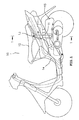
- the air intake structure of the engine of a motorcycle is disclosed, the configuration of which is illustrated in Figure 1.
- An intake pipe 11 is mounted vertically under the seat 12 of a motorcycle 10.
- the intake port 13 is covered by the seat 12, while its bottom is connected to an air cleaner 15 so as to clean the intake air from the intake port 13.
- the intake pipe 11 is on one side of a longitudinal body frame 14 of the motorcycle 10 to save up more space and to avoid interferences between the components.
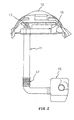
- Figure 2 is the cross sectional view of Figure 1 along the line 1-1.
- the upper end of the intake pipe 11 runs through and is fastened to an upper cover 16 so that the intake port 13 protrudes above the upper cover 16.
- the bottom of the intake pipe 11 is connected to the air cleaner 15.
- a deformable bellows pipe 17 is provided as a cushion to prevent the deformation of the said connecting components.
- the above design has the protrusion of the intake port 13 above the upper cover 16 and is only covered by the seat 12. Therefore steams and dusts are easily taken in to affect the combustion efficiency of the engine and even to shorten the service life of the engine.
- the buffer structure or the bellows pipe 17 has to be mounted to the intake pipe 11, the cost for production is high and the requirements on assembly are complicated.
- an air intake structure for an engine of a motorcycle comprising an intake chamber, an outlet chamber, a connecting pipe, one end thereof being connected to the outlet chamber, the other end thereof being connectable to the engine, and an intake pipe, wherein the intake pipe is tilted towards the connecting pipe.
- the motorcycle further comprises a shield member forming a half-enclosed space which opens in a substantially downward direction of the motorcycle, wherein an inlet opening of an upwardly extending intake pipe of the intake structure is positioned substantially inside the half-enclosed space.
- the air intake structure further comprises a drainage port being mounted to a bottom part of the intake chamber.
- said intake chamber comprises an oblique plane, preferably at an upper side thereof, to which a first end of the intake pipe is connected in a substantially vertical direction.
- said intake pipe forms an inclination with the ground between 50° to 70°.
- a second end of said intake pipe includes an inlet opening that faces to a side of the air intake structure, said inlet opening having an oval shape, a longer diameter section thereof being substantially parallel to the oblique plane.
- the air intake structure further comprises a partition wall separating said intake chamber from said outlet chamber and/or an air filter being provided between said intake pipe and said connecting pipe, preferably being positioned between said intake chamber and said outlet chamber.
- the air intake structure is preferably of the kind described above. More preferably, the shield member is positioned below the body frame and/or the seat. Therein, the motorcycle further comprising a side cover located below the seat, wherein the shield member includes a side opening that faces the side cover and the side cover covers the side opening to form the half-enclosed space.
- the intake pipe may be freely movable with regard to the body frame of the motorcycle.
- said shield member includes at least one fastening rib for fastening the shield member to the body frame and/or in that said shield member is made of rubber.
- said shield member is integrally formed on the side cover or in that said shield member is mounted to the side cover after it is formed separately from the side cover.
- a space is provided between an upper end of the intake pipe and a top wall of the shield member, large enough to prevent any direct contact therebetween caused by vibrations or shocks generated during a running of the motorcycle.
- the intake pipe allows the relative displacement generated between the body frame and other components to cope with the vibration caused when the motorcycle is running.
- the invention can simplify the designs of the components to lower the cost of production, to avoid effectively the intrusion of steams and dusts into the engine of a motorcycle and thus to optimize the service efficiency and life of the engine.
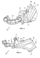
- Figures 3, 4 and 5 are respectively the block diagram, right lateral view and plan view of the air intake structure of the engine of a motorcycle according to the present invention.
- the air intake structure 30 of the engine of the motorcycle is in fact an air cleaner provided with an intake pipe 32, an intake chamber 33, an outlet chamber 34, a connecting pipe 35, a partition wall 36 and a drainage port 37.
- the opening 31 of the intake pipe 32 opens to a side to prevent any impurities to be dropped in the intake pipe 32 because of gravity.
- the bottom of the intake pipe 32 is roughly vertically connected to the oblique plane 38 of the intake chamber 33 so as to guide the air into the intake chamber 33.
- the drainage port 37 is on the bottom of the intake chamber 33 to drain the moisture coagulated in the air.
- the partition wall 36 is between the intake chamber 33 and the outlet chamber 34 to separate the two.
- the connecting pipe 35 is connected to the front end of the outlet chamber 34 to provide the cleaned air into the engine.
- Figure 6 is the cross sectional view of Figure 4 along the line 2-2.
- the partition wall 36 is integrated with an air cleaner 39 which is disposed between the intake chamber 33 and the outlet chamber 34 to clean the air in the intake chamber 33.
- the air flows in the route from the intake pipe 32 into the intake chamber 33, is provided to the outlet chamber 34 after it has cleaned by the air cleaner 39, and is provided to the engine through the connecting pipe 35 as illustrated in Figures 3 and 5.
- Figure 7 indicates the state when the air intake structure of the engine as described above is mounted to a motorcycle, preferably being of the scooter type. It is a view from inside the motorcycle to outside. The right side is the direction of the head of the motorcycle, while the left is the rear part of it. To make it easy to understand, Figure 7 only displays some of the parts in the motorcycle that relate with this invention.
- the air intake structure 30 of the engine of the motorcycle is mounted to the gear case 75 of the motorcycle, and its side is connected to a shock absorber 73.
- One end of the connecting pipe 35 is connected to the engine 72 to provide the air required by the engine 72.
- the opening 31 is under the body frame 71 and is not fastened.
- a shield member 80 is fastened to the body frame 71 and can form a half-enclosed space with the side cover 74 so that the opening 31 can be covered inside it to prevent the intrusion of steams and dusts.
- the intake pipe 32 bends towards the head of the motorcycle and forms an inclination with the ground between 50° to 70°.
- the bending design can make the intake pipe 32 to be roughly vertical to the designed vibration center of the motorcycle so that the stability of the whole structure is increased.
- FIGs 8 and 9 are block diagrams of the shield member 80 from different angles.
- the shield member 80 includes a cover 81 and two fastening ribs 82 that can be made of rubber. An opening is formed from under the cover 81 and near the side of the fastening ribs 82 while the fastening ribs 82 can be bent and fastened around the body frame 71 in Figure 7. In fact, after the shield member 80 is mounted to the body frame 71, the side of the shield member 80 originally opened is also covered by the side cover 74 in Figure 7, so that a half-enclosed space 83 opening roughly downward is formed.
- the opening 31 of the intake pipe 32 of this embodiment is inside the half-enclosed space 83 formed from the shield member 80 and the side cover 74. Therefore, compared to the design of an opening that protrudes the cover, it can optimize the effect to separate steams and dusts.
- the opening 31 of the intake pipe 32 has the suspending design, there is a space with the top of the half-enclosed space. So the relative displacement between the body frame 71 and the shield member 80 allows eliminating the needs of the existing bellows pipe design.
- the size of the shield member 80 has to be designed according to the movements of the intake pipe 32 caused during the running of the motorcycle to avoid collisions between the components. Besides, as the opening 31 of the intake pipe 32 does not require any fastening, the assembly process can be simplified.
- FIG 10 is a further illustration of the shield member 80 of the air intake structure of the engine of a motorcycle according to a second embodiment. Accordingly, it is also feasible that the shield member 80 is not structured as fastened to the body frame 71 by the fastening ribs 82 but can also be structured integrally on the side cover 74. Thus, a half-enclosed space 83 that opens roughly downwards will be formed.
- Figure 11 is a further illustration of the shield member 80 of the air intake structure of the engine of a motorcycle according to a third embodiment. It is also feasible that after the shield member 80 and the side cover 74 take shape respectively, the shield member 80 is mounted to the side cover 74. After the shield member 80 is mounted to the body frame 71, the side of the shield member 80 originally opened is covered by the side cover 74 and forms a half-enclosed space 83 the roughly opens downward.
- the air intake structure of the engine of a motorcycle and the motorcycle to which such an air intake structure is mounted is described.
- the air intake structure of the engine of the motorcycle includes a shield member and an air cleaner.
- the shield member is under a body frame of the motorcycle which extends longitudinally along the body of the motorcycle, and forms a half-enclosed space, the opening of which opens downward to prevent the entering of any impurities in the air.
- the air cleaner includes an intake pipe, the opening of which is inside the half-enclosed space.
- the intake pipe allows relative displacement to the body frame so that it is allowed that the intake pipe moves within the half-enclosed space so as to cope with the relative displacement of the components when the motorcycle jumps from the surface of the road or vibrates by itself.
- the present invention relates to the air intake structure of the engine of a motorcycle and a motorcycle that has an engine of such an air intake structure. More particularly, it relates to the air intake structure of the engine of a motorcycle that includes an air cleaner and a motorcycle that has such an air intake structure.
- the motorcycle preferably includes a body frame and an air intake structure of the engine.
- the body frame extends longitudinally along the body of the motorcycle.
- the air intake structure of the engine includes a shield member and an air cleaner.
- the shield member is under the body frame and can form a half-enclosed space that opens roughly downwards to prevent the impurities in the air from entering.
- the air cleaner also includes an intake pipe, the opening of which is inside the half-enclosed space. The intake pipe allows the relative displacement generated between itself and the body frame.
- the shield member can be a component that includes a side opening which faces the side cover of the motorcycle.
- the side opening of the shield member may be covered with the side cover to form the half-enclosed space.
- the air cleaner also includes an intake chamber, an outlet chamber, a connecting pipe, an intake pipe, a partition wall and an air filter.
- the opening of the intake pipe is under the body frame and its bottom is connected to the intake chamber.
- the intake pipe allows the relative displacement generated between itself and the body frame.
- One end of the connecting pipe is connected to the outlet chamber while the other end is connected to the engine of the motorcycle.
- the partition wall is mounted between the intake chamber and the outlet chamber to separate the two.
- the air filter can also be mounted between the intake chamber and the outlet chamber to clean the air in the intake chamber and provide it to the outlet chamber.
- the intake pipe is of a suspension type design that allows the relative displacement generated between itself and the body frame, i.e. the intake pipe is allowed to move within the half-enclosed space, the traditional design of the bellows pipe can be unnecessary.
- the opening of the intake pipe does not need to be fastened, the assembly process also becomes simpler.
Landscapes
- Engineering & Computer Science (AREA)
- Chemical & Material Sciences (AREA)
- Combustion & Propulsion (AREA)
- Mechanical Engineering (AREA)
- General Engineering & Computer Science (AREA)
- Transportation (AREA)
- Automatic Cycles, And Cycles In General (AREA)
- Cooling, Air Intake And Gas Exhaust, And Fuel Tank Arrangements In Propulsion Units (AREA)
Abstract
Description
- The present invention relates to an air intake structure for an engine of a motorcycle and to a motorcycle comprising a seat, an engine, a body frame which extends longitudinally along the body of the motorcycle, and an air intake structure for the engine.
- The engine of a motorcycle is called the heart of the cycle as it provides power. The engine of a motorcycle requires air for combustion. However, there are impurities such as steams and dusts in the air that may affect the combustion efficiency of the engine, or even cause damages to it. Therefore, an air cleaner is always provided in the air intake structure of the engine of a motorcycle to clean out the impurities in the air before the cleaned air is guided into the engine of the motorcycle for combustion.
- In the Japanese Unexamined Patent Publication No. Hei 7-101371, the air intake structure of the engine of a motorcycle is disclosed, the configuration of which is illustrated in Figure 1. An
intake pipe 11 is mounted vertically under theseat 12 of amotorcycle 10. Theintake port 13 is covered by theseat 12, while its bottom is connected to anair cleaner 15 so as to clean the intake air from theintake port 13. In addition, theintake pipe 11 is on one side of alongitudinal body frame 14 of themotorcycle 10 to save up more space and to avoid interferences between the components. - Figure 2 is the cross sectional view of Figure 1 along the line 1-1. The upper end of the
intake pipe 11 runs through and is fastened to anupper cover 16 so that theintake port 13 protrudes above theupper cover 16. The bottom of theintake pipe 11 is connected to theair cleaner 15. When the motorcycle is running, theupper cover 16 and theair cleaner 15 will have relative displacement because of the jumping of the motorcycle on the road and the vibration of the cycle itself. Therefore, in theintake pipe 11, a deformable bellowspipe 17 is provided as a cushion to prevent the deformation of the said connecting components. - The above design has the protrusion of the
intake port 13 above theupper cover 16 and is only covered by theseat 12. Therefore steams and dusts are easily taken in to affect the combustion efficiency of the engine and even to shorten the service life of the engine. In addition, as the buffer structure or thebellows pipe 17 has to be mounted to theintake pipe 11, the cost for production is high and the requirements on assembly are complicated. - Therefore, it is an object of the present invention to provide an improved air intake structure for the engine of the motorcycle and a motorcycle being provided with an improved air intake structure.
- For an air intake structure, this object is solved in an inventive manner by an air intake structure for an engine of a motorcycle, comprising an intake chamber, an outlet chamber, a connecting pipe, one end thereof being connected to the outlet chamber, the other end thereof being connectable to the engine, and an intake pipe, wherein the intake pipe is tilted towards the connecting pipe.
- Further, for a motorcycle of the above kind, this object is solved in an inventive manner in that the motorcycle further comprises a shield member forming a half-enclosed space which opens in a substantially downward direction of the motorcycle, wherein an inlet opening of an upwardly extending intake pipe of the intake structure is positioned substantially inside the half-enclosed space.
- Preferably, the air intake structure further comprises a drainage port being mounted to a bottom part of the intake chamber. Therein, said intake chamber comprises an oblique plane, preferably at an upper side thereof, to which a first end of the intake pipe is connected in a substantially vertical direction.
- Further preferably, said intake pipe forms an inclination with the ground between 50° to 70°. Therein, a second end of said intake pipe includes an inlet opening that faces to a side of the air intake structure, said inlet opening having an oval shape, a longer diameter section thereof being substantially parallel to the oblique plane.
- Further still preferably, the air intake structure further comprises a partition wall separating said intake chamber from said outlet chamber and/or an air filter being provided between said intake pipe and said connecting pipe, preferably being positioned between said intake chamber and said outlet chamber.
- Regarding a motorcycle according to the present invention, the air intake structure is preferably of the kind described above. More preferably, the shield member is positioned below the body frame and/or the seat. Therein, the motorcycle further comprising a side cover located below the seat, wherein the shield member includes a side opening that faces the side cover and the side cover covers the side opening to form the half-enclosed space.
- Further, the intake pipe may be freely movable with regard to the body frame of the motorcycle.
- Still preferably, said shield member includes at least one fastening rib for fastening the shield member to the body frame and/or in that said shield member is made of rubber. Therein, said shield member is integrally formed on the side cover or in that said shield member is mounted to the side cover after it is formed separately from the side cover.
- Further preferably, a space is provided between an upper end of the intake pipe and a top wall of the shield member, large enough to prevent any direct contact therebetween caused by vibrations or shocks generated during a running of the motorcycle.
- By providing such an improved motorcycle and such an improved air intake structure for the engine of the motorcycle, it is achieved that its intake pipe allows the relative displacement generated between the body frame and other components to cope with the vibration caused when the motorcycle is running. The invention can simplify the designs of the components to lower the cost of production, to avoid effectively the intrusion of steams and dusts into the engine of a motorcycle and thus to optimize the service efficiency and life of the engine.
- Further preferred embodiments are subject to the subclaims.
- In the following, the invention will be described in greater detail by means of embodiments thereof with reference to the accompanying drawings, wherein:
- Figs. 1 and 2 indicate the configuration mode of the air intake structure of the engine of a conventional motorcycle;
- Figs. 3, 4 and 5 are respectively the block diagram, right lateral view and plan view of the air intake structure of the engine of a motorcycle according to the present invention;
-
- Fig. 6
- is the cross sectional view of Figure 4 along the line 2-2;
- Fig. 7
- indicates the state when the air intake structure of the engine is mounted to the motorcycle;
- Fig. 8
- is the illustration of the shield member of the air intake structure according to a first embodiment;
- Fig. 9
- is the illustration of the shield member from other angle;
- Fig. 10
- is an illustration of the shield member of the air intake structure according to another embodiment; and
- Fig. 11
- is a further illustration of the shield member of the air intake structure according to still another embodiment.
- Figures 3, 4 and 5 are respectively the block diagram, right lateral view and plan view of the air intake structure of the engine of a motorcycle according to the present invention.
- The basic structure of the motorcycle corresponds to the one described before according to Figs. 1 and 2, as far as not described differently in the following.
- The
air intake structure 30 of the engine of the motorcycle is in fact an air cleaner provided with anintake pipe 32, anintake chamber 33, anoutlet chamber 34, a connectingpipe 35, apartition wall 36 and adrainage port 37. The opening 31 of theintake pipe 32 opens to a side to prevent any impurities to be dropped in theintake pipe 32 because of gravity. The bottom of theintake pipe 32 is roughly vertically connected to theoblique plane 38 of theintake chamber 33 so as to guide the air into theintake chamber 33. Thedrainage port 37 is on the bottom of theintake chamber 33 to drain the moisture coagulated in the air. Thepartition wall 36 is between theintake chamber 33 and theoutlet chamber 34 to separate the two. The connectingpipe 35 is connected to the front end of theoutlet chamber 34 to provide the cleaned air into the engine. - Figure 6 is the cross sectional view of Figure 4 along the line 2-2. The
partition wall 36 is integrated with anair cleaner 39 which is disposed between theintake chamber 33 and theoutlet chamber 34 to clean the air in theintake chamber 33. The air flows in the route from theintake pipe 32 into theintake chamber 33, is provided to theoutlet chamber 34 after it has cleaned by theair cleaner 39, and is provided to the engine through the connectingpipe 35 as illustrated in Figures 3 and 5. - Figure 7 indicates the state when the air intake structure of the engine as described above is mounted to a motorcycle, preferably being of the scooter type. It is a view from inside the motorcycle to outside. The right side is the direction of the head of the motorcycle, while the left is the rear part of it. To make it easy to understand, Figure 7 only displays some of the parts in the motorcycle that relate with this invention. The
air intake structure 30 of the engine of the motorcycle is mounted to thegear case 75 of the motorcycle, and its side is connected to ashock absorber 73. One end of the connectingpipe 35 is connected to theengine 72 to provide the air required by theengine 72. Theopening 31 is under thebody frame 71 and is not fastened. Ashield member 80 is fastened to thebody frame 71 and can form a half-enclosed space with theside cover 74 so that theopening 31 can be covered inside it to prevent the intrusion of steams and dusts. In addition, theintake pipe 32 bends towards the head of the motorcycle and forms an inclination with the ground between 50° to 70°. The bending design can make theintake pipe 32 to be roughly vertical to the designed vibration center of the motorcycle so that the stability of the whole structure is increased. - Figures 8 and 9 are block diagrams of the
shield member 80 from different angles. Theshield member 80 includes acover 81 and twofastening ribs 82 that can be made of rubber. An opening is formed from under thecover 81 and near the side of thefastening ribs 82 while thefastening ribs 82 can be bent and fastened around thebody frame 71 in Figure 7. In fact, after theshield member 80 is mounted to thebody frame 71, the side of theshield member 80 originally opened is also covered by theside cover 74 in Figure 7, so that a half-enclosedspace 83 opening roughly downward is formed. - The
opening 31 of theintake pipe 32 of this embodiment is inside the half-enclosedspace 83 formed from theshield member 80 and theside cover 74. Therefore, compared to the design of an opening that protrudes the cover, it can optimize the effect to separate steams and dusts. In addition, because theopening 31 of theintake pipe 32 has the suspending design, there is a space with the top of the half-enclosed space. So the relative displacement between thebody frame 71 and theshield member 80 allows eliminating the needs of the existing bellows pipe design. The size of theshield member 80 has to be designed according to the movements of theintake pipe 32 caused during the running of the motorcycle to avoid collisions between the components. Besides, as theopening 31 of theintake pipe 32 does not require any fastening, the assembly process can be simplified. - Figure 10 is a further illustration of the
shield member 80 of the air intake structure of the engine of a motorcycle according to a second embodiment. Accordingly, it is also feasible that theshield member 80 is not structured as fastened to thebody frame 71 by thefastening ribs 82 but can also be structured integrally on theside cover 74. Thus, a half-enclosedspace 83 that opens roughly downwards will be formed. - Figure 11 is a further illustration of the
shield member 80 of the air intake structure of the engine of a motorcycle according to a third embodiment. It is also feasible that after theshield member 80 and theside cover 74 take shape respectively, theshield member 80 is mounted to theside cover 74. After theshield member 80 is mounted to thebody frame 71, the side of theshield member 80 originally opened is covered by theside cover 74 and forms a half-enclosedspace 83 the roughly opens downward. - The technical contents and technical features of the present invention are described as the above. However, ordinary skilled in the art may still, based on the illustrations and descriptions of this invention, make further alternatives or improvements within the spirit of this invention. Therefore, the scope of the protection of this invention shall not be limited to the above examples, but shall include any alternatives and improvements within the claims of this application.
- Above, the air intake structure of the engine of a motorcycle and the motorcycle to which such an air intake structure is mounted is described. Therein preferably, the air intake structure of the engine of the motorcycle includes a shield member and an air cleaner. The shield member is under a body frame of the motorcycle which extends longitudinally along the body of the motorcycle, and forms a half-enclosed space, the opening of which opens downward to prevent the entering of any impurities in the air. The air cleaner includes an intake pipe, the opening of which is inside the half-enclosed space. In addition, the intake pipe allows relative displacement to the body frame so that it is allowed that the intake pipe moves within the half-enclosed space so as to cope with the relative displacement of the components when the motorcycle jumps from the surface of the road or vibrates by itself.
- In other words, the present invention relates to the air intake structure of the engine of a motorcycle and a motorcycle that has an engine of such an air intake structure. More particularly, it relates to the air intake structure of the engine of a motorcycle that includes an air cleaner and a motorcycle that has such an air intake structure.
- As explained above, the motorcycle preferably includes a body frame and an air intake structure of the engine. The body frame extends longitudinally along the body of the motorcycle. The air intake structure of the engine includes a shield member and an air cleaner. The shield member is under the body frame and can form a half-enclosed space that opens roughly downwards to prevent the impurities in the air from entering. The air cleaner also includes an intake pipe, the opening of which is inside the half-enclosed space. The intake pipe allows the relative displacement generated between itself and the body frame.
- The shield member can be a component that includes a side opening which faces the side cover of the motorcycle. The side opening of the shield member may be covered with the side cover to form the half-enclosed space.
- In terms of the specific structures, the air cleaner also includes an intake chamber, an outlet chamber, a connecting pipe, an intake pipe, a partition wall and an air filter. The opening of the intake pipe is under the body frame and its bottom is connected to the intake chamber. The intake pipe allows the relative displacement generated between itself and the body frame. One end of the connecting pipe is connected to the outlet chamber while the other end is connected to the engine of the motorcycle. The partition wall is mounted between the intake chamber and the outlet chamber to separate the two. The air filter can also be mounted between the intake chamber and the outlet chamber to clean the air in the intake chamber and provide it to the outlet chamber. Besides, there can be another drainage port on the bottom of the intake chamber to drain the moisture coagulated in the air.
- As the intake pipe is of a suspension type design that allows the relative displacement generated between itself and the body frame, i.e. the intake pipe is allowed to move within the half-enclosed space, the traditional design of the bellows pipe can be unnecessary. In addition, as the opening of the intake pipe does not need to be fastened, the assembly process also becomes simpler.
Claims (14)
- Air intake structure for an engine of a motorcycle, comprising:an intake chamber (33);an outlet chamber (34);a connecting pipe (35), one end thereof being connected to the outlet chamber (34), the other end thereof being connectable to the engine (72); andan intake pipe (32), wherein the intake pipe (32) is tilted towards the connecting pipe (35).
- Air intake structure according to claim 1, characterized by further comprising a drainage port (37) being mounted to a bottom part of the intake chamber (33).
- Air intake structure according to claim 1 or 2, characterized in that said intake chamber (33) comprises an oblique plane (38), preferably at an upper side thereof, to which a first end of the intake pipe (32) is connected in a substantially vertical direction.
- Air intake structure according to at least one of the claims 1 to 3, characterized in that said intake pipe (32) forms an inclination with the ground between 50° to 70°.
- Air intake structure according to at least one of the claims 1 to 4, characterized in that at a second end of said intake pipe (32) includes an inlet opening (31) that faces to a side of the air intake structure (30).
- Air intake structure according to claim 5, characterized in that said inlet opening (31) has an oval shape, a longer diameter section thereof being substantially parallel to the oblique plane (38).
- Air intake structure according to at least one of the claims 1 to 6, characterized by further comprising a partition wall (36) separating said intake chamber (33) from said outlet chamber (34) and/or an air filter (39) being provided between said intake pipe (32) and said connecting pipe (35), preferably being positioned between said intake chamber (33) and said outlet chamber (34).
- Motorcycle comprising a seat (12), an engine (72), a body frame (71) which extends longitudinally along the body of the motorcycle, and an air intake structure (30) for the engine (72), preferably an air intake structure according to at least one of the claims 1 to 7, characterized in that the motorcycle further comprises a shield member (80) forming a half-enclosed space (83) which opens in a substantially downward direction of the motorcycle, wherein an inlet opening (31) of an upwardly extending intake pipe (32) of the intake structure (30) is positioned substantially inside the half-enclosed space (85).
- Motorcycle according to claim 8, characterized in that the shield member (80) is positioned below the body frame (71) and/or the seat (12).
- Motorcycle according to claim 8 or 9, characterized in that further comprising a side cover (74) located below the seat (12), wherein the shield member (80) includes a side opening that faces the side cover (74) and the side cover (74) covers the side opening to form the half-enclosed space (83).
- Motorcycle according to at least one of the claims 8 to 10, characterized in that the intake pipe (32) is freely movable with regard to the body frame (71) of the motorcycle.
- Motorcycle according to at least one of the claims 8 to 11, characterized in that said shield member (80) includes at least one fastening rib (82) for fastening the shield member (80) to the body frame (71) and/or in that said shield member (80) is made of rubber.
- Motorcycle according to at least one of the claims 8 to 12, characterized in that said shield member (80) is integrally formed on the side cover (74) or in that said shield member (80) is mounted to the side cover (74) after it is formed separately from the side cover (74).
- Motorcycle according to at least one of the claims 8 to 13, characterized in that a space is provided between an upper end of the intake pipe (32) and a top wall of the shield member (80), large enough to prevent any direct contact therebetween caused by vibrations or shocks generated during a running of the motorcycle.
Applications Claiming Priority (2)
| Application Number | Priority Date | Filing Date | Title |
|---|---|---|---|
| CNB031237185A CN100406339C (en) | 2003-05-20 | 2003-05-20 | Two-wheeled motor vehicle with engine intake structure |
| CN03123718 | 2003-05-20 |
Publications (3)
| Publication Number | Publication Date |
|---|---|
| EP1479603A2 true EP1479603A2 (en) | 2004-11-24 |
| EP1479603A3 EP1479603A3 (en) | 2008-05-21 |
| EP1479603B1 EP1479603B1 (en) | 2019-07-03 |
Family
ID=33035153
Family Applications (1)
| Application Number | Title | Priority Date | Filing Date |
|---|---|---|---|
| EP04011944.8A Expired - Lifetime EP1479603B1 (en) | 2003-05-20 | 2004-05-19 | Air intake structure for an engine of a motorcycle and motorcycle comprising an air intake structure |
Country Status (3)
| Country | Link |
|---|---|
| EP (1) | EP1479603B1 (en) |
| JP (1) | JP2004345634A (en) |
| CN (1) | CN100406339C (en) |
Cited By (2)
| Publication number | Priority date | Publication date | Assignee | Title |
|---|---|---|---|---|
| US7612687B2 (en) | 2006-03-27 | 2009-11-03 | Denso Corporation | On-board unit |
| CN114294135A (en) * | 2022-01-05 | 2022-04-08 | 浙江钱江摩托股份有限公司 | Intake structure of motorcycle engine |
Families Citing this family (6)
| Publication number | Priority date | Publication date | Assignee | Title |
|---|---|---|---|---|
| DE102005003126A1 (en) * | 2005-01-21 | 2006-08-03 | Elringklinger Ag | Structural component, in particular shielding |
| CN101348143B (en) * | 2007-07-20 | 2012-04-04 | 光阳工业股份有限公司 | Motorcycle side cover structure |
| CN102305158A (en) * | 2011-08-12 | 2012-01-04 | 重庆长安汽车股份有限公司 | Air inlet system of miniature automobile engine |
| WO2013184045A1 (en) * | 2012-06-07 | 2013-12-12 | Volvo Construction Equipment Ab | An arrangement and a method for controlling the temperature of air being fed to a vehicle engine |
| JP6680822B2 (en) * | 2018-03-30 | 2020-04-15 | 本田技研工業株式会社 | Intake structure of internal combustion engine for saddle type vehicle |
| JP7309681B2 (en) * | 2020-11-10 | 2023-07-18 | 本田技研工業株式会社 | saddle-riding vehicle |
Citations (1)
| Publication number | Priority date | Publication date | Assignee | Title |
|---|---|---|---|---|
| JPH07101371A (en) | 1993-10-08 | 1995-04-18 | Suzuki Motor Corp | Intake device for scooter type vehicle |
Family Cites Families (25)
| Publication number | Priority date | Publication date | Assignee | Title |
|---|---|---|---|---|
| JPS6010200Y2 (en) * | 1980-04-11 | 1985-04-08 | 本田技研工業株式会社 | Motorcycle air cleaner device |
| ES518472A0 (en) * | 1981-12-23 | 1983-12-01 | Honda Motor Co Ltd | A BELT TRANSMISSION DEVICE. |
| JPS60102423U (en) * | 1983-12-19 | 1985-07-12 | スズキ株式会社 | Motorcycle engine cooling air exhaust device |
| JPS60174323A (en) * | 1984-02-20 | 1985-09-07 | Suzuki Motor Co Ltd | Intake suction apparatus for small-sized car |
| JPS61175124A (en) * | 1985-01-29 | 1986-08-06 | Honda Motor Co Ltd | Suction device in power unit |
| JP2716720B2 (en) * | 1988-03-14 | 1998-02-18 | 本田技研工業株式会社 | Motor cleaner air cleaner chamber mounting structure |
| JP2761117B2 (en) * | 1991-03-20 | 1998-06-04 | 本田技研工業株式会社 | Air intake device for scooter type vehicle |
| JPH0565086A (en) * | 1991-09-06 | 1993-03-19 | Suzuki Motor Corp | Scooter engine cooling system |
| JPH06219366A (en) * | 1993-01-25 | 1994-08-09 | Suzuki Motor Corp | Intake device for scooter type vehicle |
| JP3373921B2 (en) * | 1993-12-27 | 2003-02-04 | 本田技研工業株式会社 | Vaporizer warmer for motorcycles |
| JP3609121B2 (en) * | 1994-06-11 | 2005-01-12 | 本田技研工業株式会社 | Scooter air intake |
| JPH0811765A (en) * | 1994-06-28 | 1996-01-16 | Suzuki Motor Corp | Intake hose mounting structure for the second air cleaner |
| JPH0814036A (en) * | 1994-06-28 | 1996-01-16 | Suzuki Motor Corp | Intake hose mounting structure for the second air cleaner |
| JP3751077B2 (en) * | 1996-05-17 | 2006-03-01 | 本田技研工業株式会社 | Intake air intake structure for scooter type vehicles |
| JPH11171075A (en) * | 1997-12-09 | 1999-06-29 | Yamaha Motor Co Ltd | Motorcycle |
| JP4145379B2 (en) * | 1998-01-17 | 2008-09-03 | 本田技研工業株式会社 | Scooter type vehicle intake system |
| JP2000219186A (en) * | 1999-01-29 | 2000-08-08 | Honda Motor Co Ltd | Bicycle with internal combustion engine |
| JP4249345B2 (en) * | 1999-08-31 | 2009-04-02 | ヤマハ発動機株式会社 | Scooter type motorcycle air cleaner |
| JP4240431B2 (en) * | 1999-09-24 | 2009-03-18 | 本田技研工業株式会社 | Motorcycle air cleaner equipment |
| JP3974333B2 (en) * | 2001-01-19 | 2007-09-12 | 本田技研工業株式会社 | Air cleaner structure for vehicles |
| JP2003176762A (en) * | 2001-09-27 | 2003-06-27 | Yamaha Motor Co Ltd | Fuel hose mounting structure for fuel injection engine |
| JP2003127950A (en) * | 2001-10-23 | 2003-05-08 | Suzuki Motor Corp | Arrangement structure of air cleaner in motorcycle |
| JP3978335B2 (en) * | 2001-12-20 | 2007-09-19 | ヤマハ発動機株式会社 | New air intake structure of scooter type motorcycle |
| JP2004231172A (en) * | 2003-01-10 | 2004-08-19 | Yamaha Motor Co Ltd | Motorcycle air cleaner device |
| JP4379864B2 (en) * | 2003-09-12 | 2009-12-09 | ヤマハ発動機株式会社 | Scooter type motorcycle |
-
2003
- 2003-05-20 CN CNB031237185A patent/CN100406339C/en not_active Expired - Fee Related
-
2004
- 2004-05-19 EP EP04011944.8A patent/EP1479603B1/en not_active Expired - Lifetime
- 2004-05-20 JP JP2004150418A patent/JP2004345634A/en not_active Withdrawn
Patent Citations (1)
| Publication number | Priority date | Publication date | Assignee | Title |
|---|---|---|---|---|
| JPH07101371A (en) | 1993-10-08 | 1995-04-18 | Suzuki Motor Corp | Intake device for scooter type vehicle |
Cited By (2)
| Publication number | Priority date | Publication date | Assignee | Title |
|---|---|---|---|---|
| US7612687B2 (en) | 2006-03-27 | 2009-11-03 | Denso Corporation | On-board unit |
| CN114294135A (en) * | 2022-01-05 | 2022-04-08 | 浙江钱江摩托股份有限公司 | Intake structure of motorcycle engine |
Also Published As
| Publication number | Publication date |
|---|---|
| JP2004345634A (en) | 2004-12-09 |
| CN1548331A (en) | 2004-11-24 |
| EP1479603A3 (en) | 2008-05-21 |
| EP1479603B1 (en) | 2019-07-03 |
| CN100406339C (en) | 2008-07-30 |
Similar Documents
| Publication | Publication Date | Title |
|---|---|---|
| CN103161622B (en) | Intake system of vehicle engine installed in engine compartment | |
| JP6208647B2 (en) | Rear fuel tank support structure for saddle-ride type vehicles | |
| US20090236175A1 (en) | Exhaust structure of motorcycle | |
| JP2009035160A (en) | Fender liner structure | |
| EP1479603A2 (en) | Air intake structure for an engine of a motorcycle and motorcycle comprising an air intake structure | |
| US10001092B2 (en) | Air cleaner for motorcycle | |
| EP2639443B1 (en) | Intake structure for saddle-ride type vehicle | |
| JP6086889B2 (en) | Rear fuel tank | |
| WO2008072416A1 (en) | Oil pan structure for engine | |
| CN104421070B (en) | Motorcycle-type vehicle | |
| JP2009235930A (en) | Cooling fin structure for vehicle-mounted internal combustion engine | |
| CN105644626B (en) | Suspension member | |
| US10286979B2 (en) | Air cleaner structure of saddle-ride type vehicle | |
| EP2562068B1 (en) | Straddle-ride type vehicle with mudguard structure | |
| CN103182929A (en) | Straddle-type vehicle | |
| CN103452711B (en) | A kind of air inflow structure of automobile air cleaner | |
| ITTO971099A1 (en) | MOTORBIKE EQUIPPED WITH AIR FILTER AND OSCI LLANTE MOTORPROPULSOR UNIT. | |
| CN111148685B (en) | Cover structure of saddle-riding vehicle | |
| CN112963274B (en) | Air filter intake pipe mounting structure and all-terrain vehicle | |
| JP6245970B2 (en) | Motorcycle | |
| JP2006083840A (en) | Motorcycle air filter | |
| US11840302B2 (en) | Air cleaner | |
| TWI261553B (en) | Air intake structure of a motorcycle engine and a motorcycle provided with same | |
| CN111980834B (en) | Air intake structure for vehicle | |
| JP4094969B2 (en) | Reserve tank |
Legal Events
| Date | Code | Title | Description |
|---|---|---|---|
| PUAI | Public reference made under article 153(3) epc to a published international application that has entered the european phase |
Free format text: ORIGINAL CODE: 0009012 |
|
| AK | Designated contracting states |
Kind code of ref document: A2 Designated state(s): AT BE BG CH CY CZ DE DK EE ES FI FR GB GR HU IE IT LI LU MC NL PL PT RO SE SI SK TR |
|
| AX | Request for extension of the european patent |
Extension state: AL HR LT LV MK |
|
| PUAL | Search report despatched |
Free format text: ORIGINAL CODE: 0009013 |
|
| AK | Designated contracting states |
Kind code of ref document: A3 Designated state(s): AT BE BG CH CY CZ DE DK EE ES FI FR GB GR HU IE IT LI LU MC NL PL PT RO SE SI SK TR |
|
| AX | Request for extension of the european patent |
Extension state: AL HR LT LV MK |
|
| 17P | Request for examination filed |
Effective date: 20080514 |
|
| 17Q | First examination report despatched |
Effective date: 20080808 |
|
| AKX | Designation fees paid |
Designated state(s): AT BE BG CH CY CZ DE DK EE ES FI FR GB GR HU IE IT LI LU MC NL PL PT RO SE SI SK TR |
|
| REG | Reference to a national code |
Ref country code: DE Ref legal event code: R079 Ref document number: 602004054100 Country of ref document: DE Free format text: PREVIOUS MAIN CLASS: B62M0007120000 Ipc: B62K0011100000 |
|
| RIC1 | Information provided on ipc code assigned before grant |
Ipc: B62K 11/10 19680901AFI20181012BHEP Ipc: F02M 35/16 19680901ALI20181012BHEP Ipc: F02M 35/02 19680901ALI20181012BHEP Ipc: F02M 35/10 19680901ALI20181012BHEP Ipc: B62M 7/12 19680901ALI20181012BHEP |
|
| GRAP | Despatch of communication of intention to grant a patent |
Free format text: ORIGINAL CODE: EPIDOSNIGR1 |
|
| STAA | Information on the status of an ep patent application or granted ep patent |
Free format text: STATUS: GRANT OF PATENT IS INTENDED |
|
| INTG | Intention to grant announced |
Effective date: 20190107 |
|
| RIC1 | Information provided on ipc code assigned before grant |
Ipc: F02M 35/10 20060101ALI20181012BHEP Ipc: F02M 35/16 20060101ALI20181012BHEP Ipc: F02M 35/02 20060101ALI20181012BHEP Ipc: B62M 7/12 20060101ALI20181012BHEP Ipc: B62K 11/10 20060101AFI20181012BHEP |
|
| GRAS | Grant fee paid |
Free format text: ORIGINAL CODE: EPIDOSNIGR3 |
|
| GRAA | (expected) grant |
Free format text: ORIGINAL CODE: 0009210 |
|
| STAA | Information on the status of an ep patent application or granted ep patent |
Free format text: STATUS: THE PATENT HAS BEEN GRANTED |
|
| AK | Designated contracting states |
Kind code of ref document: B1 Designated state(s): AT BE BG CH CY CZ DE DK EE ES FI FR GB GR HU IE IT LI LU MC NL PL PT RO SE SI SK TR |
|
| REG | Reference to a national code |
Ref country code: GB Ref legal event code: FG4D |
|
| REG | Reference to a national code |
Ref country code: CH Ref legal event code: EP Ref country code: AT Ref legal event code: REF Ref document number: 1150644 Country of ref document: AT Kind code of ref document: T Effective date: 20190715 |
|
| REG | Reference to a national code |
Ref country code: DE Ref legal event code: R096 Ref document number: 602004054100 Country of ref document: DE |
|
| REG | Reference to a national code |
Ref country code: IE Ref legal event code: FG4D |
|
| REG | Reference to a national code |
Ref country code: NL Ref legal event code: MP Effective date: 20190703 |
|
| REG | Reference to a national code |
Ref country code: AT Ref legal event code: MK05 Ref document number: 1150644 Country of ref document: AT Kind code of ref document: T Effective date: 20190703 |
|
| PG25 | Lapsed in a contracting state [announced via postgrant information from national office to epo] |
Ref country code: PT Free format text: LAPSE BECAUSE OF FAILURE TO SUBMIT A TRANSLATION OF THE DESCRIPTION OR TO PAY THE FEE WITHIN THE PRESCRIBED TIME-LIMIT Effective date: 20191104 Ref country code: SE Free format text: LAPSE BECAUSE OF FAILURE TO SUBMIT A TRANSLATION OF THE DESCRIPTION OR TO PAY THE FEE WITHIN THE PRESCRIBED TIME-LIMIT Effective date: 20190703 Ref country code: NL Free format text: LAPSE BECAUSE OF FAILURE TO SUBMIT A TRANSLATION OF THE DESCRIPTION OR TO PAY THE FEE WITHIN THE PRESCRIBED TIME-LIMIT Effective date: 20190703 Ref country code: BG Free format text: LAPSE BECAUSE OF FAILURE TO SUBMIT A TRANSLATION OF THE DESCRIPTION OR TO PAY THE FEE WITHIN THE PRESCRIBED TIME-LIMIT Effective date: 20191003 Ref country code: CZ Free format text: LAPSE BECAUSE OF FAILURE TO SUBMIT A TRANSLATION OF THE DESCRIPTION OR TO PAY THE FEE WITHIN THE PRESCRIBED TIME-LIMIT Effective date: 20190703 Ref country code: FI Free format text: LAPSE BECAUSE OF FAILURE TO SUBMIT A TRANSLATION OF THE DESCRIPTION OR TO PAY THE FEE WITHIN THE PRESCRIBED TIME-LIMIT Effective date: 20190703 Ref country code: AT Free format text: LAPSE BECAUSE OF FAILURE TO SUBMIT A TRANSLATION OF THE DESCRIPTION OR TO PAY THE FEE WITHIN THE PRESCRIBED TIME-LIMIT Effective date: 20190703 |
|
| PG25 | Lapsed in a contracting state [announced via postgrant information from national office to epo] |
Ref country code: ES Free format text: LAPSE BECAUSE OF FAILURE TO SUBMIT A TRANSLATION OF THE DESCRIPTION OR TO PAY THE FEE WITHIN THE PRESCRIBED TIME-LIMIT Effective date: 20190703 Ref country code: GR Free format text: LAPSE BECAUSE OF FAILURE TO SUBMIT A TRANSLATION OF THE DESCRIPTION OR TO PAY THE FEE WITHIN THE PRESCRIBED TIME-LIMIT Effective date: 20191004 |
|
| PG25 | Lapsed in a contracting state [announced via postgrant information from national office to epo] |
Ref country code: TR Free format text: LAPSE BECAUSE OF FAILURE TO SUBMIT A TRANSLATION OF THE DESCRIPTION OR TO PAY THE FEE WITHIN THE PRESCRIBED TIME-LIMIT Effective date: 20190703 |
|
| PG25 | Lapsed in a contracting state [announced via postgrant information from national office to epo] |
Ref country code: DK Free format text: LAPSE BECAUSE OF FAILURE TO SUBMIT A TRANSLATION OF THE DESCRIPTION OR TO PAY THE FEE WITHIN THE PRESCRIBED TIME-LIMIT Effective date: 20190703 Ref country code: EE Free format text: LAPSE BECAUSE OF FAILURE TO SUBMIT A TRANSLATION OF THE DESCRIPTION OR TO PAY THE FEE WITHIN THE PRESCRIBED TIME-LIMIT Effective date: 20190703 Ref country code: RO Free format text: LAPSE BECAUSE OF FAILURE TO SUBMIT A TRANSLATION OF THE DESCRIPTION OR TO PAY THE FEE WITHIN THE PRESCRIBED TIME-LIMIT Effective date: 20190703 Ref country code: PL Free format text: LAPSE BECAUSE OF FAILURE TO SUBMIT A TRANSLATION OF THE DESCRIPTION OR TO PAY THE FEE WITHIN THE PRESCRIBED TIME-LIMIT Effective date: 20190703 |
|
| PG25 | Lapsed in a contracting state [announced via postgrant information from national office to epo] |
Ref country code: SK Free format text: LAPSE BECAUSE OF FAILURE TO SUBMIT A TRANSLATION OF THE DESCRIPTION OR TO PAY THE FEE WITHIN THE PRESCRIBED TIME-LIMIT Effective date: 20190703 |
|
| REG | Reference to a national code |
Ref country code: DE Ref legal event code: R097 Ref document number: 602004054100 Country of ref document: DE |
|
| PLBE | No opposition filed within time limit |
Free format text: ORIGINAL CODE: 0009261 |
|
| STAA | Information on the status of an ep patent application or granted ep patent |
Free format text: STATUS: NO OPPOSITION FILED WITHIN TIME LIMIT |
|
| 26N | No opposition filed |
Effective date: 20200603 |
|
| PG25 | Lapsed in a contracting state [announced via postgrant information from national office to epo] |
Ref country code: SI Free format text: LAPSE BECAUSE OF FAILURE TO SUBMIT A TRANSLATION OF THE DESCRIPTION OR TO PAY THE FEE WITHIN THE PRESCRIBED TIME-LIMIT Effective date: 20190703 |
|
| PG25 | Lapsed in a contracting state [announced via postgrant information from national office to epo] |
Ref country code: LI Free format text: LAPSE BECAUSE OF NON-PAYMENT OF DUE FEES Effective date: 20200531 Ref country code: CH Free format text: LAPSE BECAUSE OF NON-PAYMENT OF DUE FEES Effective date: 20200531 Ref country code: MC Free format text: LAPSE BECAUSE OF FAILURE TO SUBMIT A TRANSLATION OF THE DESCRIPTION OR TO PAY THE FEE WITHIN THE PRESCRIBED TIME-LIMIT Effective date: 20190703 |
|
| REG | Reference to a national code |
Ref country code: BE Ref legal event code: MM Effective date: 20200531 |
|
| GBPC | Gb: european patent ceased through non-payment of renewal fee |
Effective date: 20200519 |
|
| PG25 | Lapsed in a contracting state [announced via postgrant information from national office to epo] |
Ref country code: LU Free format text: LAPSE BECAUSE OF NON-PAYMENT OF DUE FEES Effective date: 20200519 |
|
| PG25 | Lapsed in a contracting state [announced via postgrant information from national office to epo] |
Ref country code: GB Free format text: LAPSE BECAUSE OF NON-PAYMENT OF DUE FEES Effective date: 20200519 Ref country code: IE Free format text: LAPSE BECAUSE OF NON-PAYMENT OF DUE FEES Effective date: 20200519 |
|
| PG25 | Lapsed in a contracting state [announced via postgrant information from national office to epo] |
Ref country code: BE Free format text: LAPSE BECAUSE OF NON-PAYMENT OF DUE FEES Effective date: 20200531 |
|
| PG25 | Lapsed in a contracting state [announced via postgrant information from national office to epo] |
Ref country code: CY Free format text: LAPSE BECAUSE OF FAILURE TO SUBMIT A TRANSLATION OF THE DESCRIPTION OR TO PAY THE FEE WITHIN THE PRESCRIBED TIME-LIMIT Effective date: 20190703 |
|
| P01 | Opt-out of the competence of the unified patent court (upc) registered |
Effective date: 20230527 |
|
| PGFP | Annual fee paid to national office [announced via postgrant information from national office to epo] |
Ref country code: IT Payment date: 20230526 Year of fee payment: 20 Ref country code: FR Payment date: 20230525 Year of fee payment: 20 Ref country code: DE Payment date: 20230519 Year of fee payment: 20 |
|
| REG | Reference to a national code |
Ref country code: DE Ref legal event code: R071 Ref document number: 602004054100 Country of ref document: DE |