EP1479589A2 - Trolley - Google Patents
Trolley Download PDFInfo
- Publication number
- EP1479589A2 EP1479589A2 EP20040252835 EP04252835A EP1479589A2 EP 1479589 A2 EP1479589 A2 EP 1479589A2 EP 20040252835 EP20040252835 EP 20040252835 EP 04252835 A EP04252835 A EP 04252835A EP 1479589 A2 EP1479589 A2 EP 1479589A2
- Authority
- EP
- European Patent Office
- Prior art keywords
- trolley
- platform
- wheels
- wheel
- load
- Prior art date
- Legal status (The legal status is an assumption and is not a legal conclusion. Google has not performed a legal analysis and makes no representation as to the accuracy of the status listed.)
- Withdrawn
Links
- 239000002184 metal Substances 0.000 claims description 4
- 208000027418 Wounds and injury Diseases 0.000 description 1
- 238000010276 construction Methods 0.000 description 1
- 230000006378 damage Effects 0.000 description 1
- 208000014674 injury Diseases 0.000 description 1
- 230000004048 modification Effects 0.000 description 1
- 238000012986 modification Methods 0.000 description 1
- 235000020004 porter Nutrition 0.000 description 1
- 230000003019 stabilising effect Effects 0.000 description 1
- 238000003466 welding Methods 0.000 description 1
Images

Classifications
-
- B—PERFORMING OPERATIONS; TRANSPORTING
- B62—LAND VEHICLES FOR TRAVELLING OTHERWISE THAN ON RAILS
- B62B—HAND-PROPELLED VEHICLES, e.g. HAND CARTS OR PERAMBULATORS; SLEDGES
- B62B1/00—Hand carts having only one axis carrying one or more transport wheels; Equipment therefor
- B62B1/10—Hand carts having only one axis carrying one or more transport wheels; Equipment therefor in which the load is intended to be transferred totally to the wheels
-
- B—PERFORMING OPERATIONS; TRANSPORTING
- B62—LAND VEHICLES FOR TRAVELLING OTHERWISE THAN ON RAILS
- B62B—HAND-PROPELLED VEHICLES, e.g. HAND CARTS OR PERAMBULATORS; SLEDGES
- B62B2203/00—Grasping, holding, supporting the objects
- B62B2203/05—Rocking means for facilitating tilting of the cart, e.g. by loading
Definitions
- This invention relates to a trolley such as is used to transport heavy or bulky loads.
- Trolleys of this general type such as the well known porter's trolley, are widely used and rely, when picking up a load, on the operator's strength to pivot the trolley with it's load about the wheels of the trolley. This can be difficult with a heavy load and indeed can cause injury to the user.
- the present invention is a trolley having a load carrying platform, a lifting toe extending upwardly from the platform at one end, the front end, of the platform, at least one wheel adjacent the front end of the platform, and a curved member extending back from the bottom of the lifting toe towards the wheel or wheels.
- a transversely extending foot plate is provided beneath the platform at the rear of the wheels.
- the curved member may be a metal plate.
- More than one curved member in the form of curved bars may be provided.
- At least one handle is provided at the rear end of the trolley.
- a trolley according to the present invention has a platform 12 for supporting a load and a pair of wheels 14, one at each side of the platform 12, mounted beneath the platform on an axle 16 carried by a support at each side, each support comprising a front member 18, a middle member 20 and a rear member 22.
- a foot plate 24 extends between the axle supports behind the axle.
- the platform 12 is defined by metal bars, there being two side bars 26, to which the support members are secured, a central bar 28 parallel to the side bars, and three transverse bars 30 secured, in this embodiment by welding, to the side bars and the central bar.
- wheel guards 32 At the sides of the platform, above the wheels are provided wheel guards 32.
- a lifting toe 34 in the form of a metal plate which extends across and upwardly from the platform 12. Beneath the platform 12 the lifting toe is extended in a smooth curve back towards the wheels by a member 36.
- the rear of the 36 is supported by members 37 secured to the members 18.
- the side bars 26 extend back beyond the rear of the platform 12 and are terminated by handles 40.
- the trolley In use, the trolley is moved to a load and the lifting toe 34 is inserted beneath the load, the wheels 14 at this time being off the ground as shown in Fig 1. From this position, the operator, standing on the foot plate 24 if necessary, can pull back on the load, or on the handles 40 to cause the trolley to rotate on the curved member 36 until the wheels 14 come into contact with the ground so that the user can then move the trolley and the load. It should be noted that the force required to rotate the trolley on the member 36 is less than that required with known trolleys which rotate about the contact points of their wheels with the ground, i.e. some distance below the platform.
- the embodiment described may be modified, for example by having a single wheel or a single handle extending across between the ends of the side bars. If a short trolley is desired then the handles could be dispensed with altogether, the loaded trolley then being manoeuvred by pushing or pulling the load itself.
- the curved member 36 may be integral with the lifting toe 34 or these may be separate components. Also, the sheet forming the toe 34 and/or the member 36 could be perforated, and indeed the member 36 could be replaced by two or more transversely spaced curved bars.
- the transverse bars 30 may be curved to provide a concave platform rather than a plane one, or may be shaped to match the outline of a specific load. Also, means such as straps or clamps, may be provided to secure loads on the platform.
- the side bars can be made adjustable in length, e.g. by being telescopic, to suit particular loads and/or operators, and stabilising wheels or legs may be provided.
Landscapes
- Engineering & Computer Science (AREA)
- Chemical & Material Sciences (AREA)
- Combustion & Propulsion (AREA)
- Transportation (AREA)
- Mechanical Engineering (AREA)
- Handcart (AREA)
Abstract
A trolley has a load carrying platform 12, a lifting toe 34 extending upwardly from the
platform 12 at one end, the front end, of the platform, at least one wheel 14 adjacent the front
end of the platform, and a curved member 36 extending back from the bottom of the lifting
toe 34 towards the wheel or wheels 14.
Description
- This invention relates to a trolley such as is used to transport heavy or bulky loads.
- Trolleys of this general type, such as the well known porter's trolley, are widely used and rely, when picking up a load, on the operator's strength to pivot the trolley with it's load about the wheels of the trolley. This can be difficult with a heavy load and indeed can cause injury to the user.
- It is an object of the present invention to obviate or mitigate this problem.
- The present invention is a trolley having a load carrying platform, a lifting toe extending upwardly from the platform at one end, the front end, of the platform, at least one wheel adjacent the front end of the platform, and a curved member extending back from the bottom of the lifting toe towards the wheel or wheels.
- Preferably there are two wheels, one at each side of the trolley.
- Preferably, a transversely extending foot plate is provided beneath the platform at the rear of the wheels.
- The curved member may be a metal plate.
- More than one curved member in the form of curved bars may be provided.
- Preferably, at least one handle is provided at the rear end of the trolley.
- Embodiments of the present invention will now be described, by way of example, with reference to the accompanying drawings, in which:-
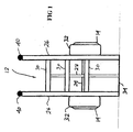
- Fig. 1 is a front view of a trolley according to the present invention;
- Fig. 2 is a side view of the trolley of Fig 1; and
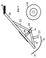
- Fig 3 is a side view similar to Fig 2 but with some parts removed to show more clearly the construction of the trolley.
-
- Referring now to the drawings, a trolley according to the present invention has a
platform 12 for supporting a load and a pair ofwheels 14, one at each side of theplatform 12, mounted beneath the platform on anaxle 16 carried by a support at each side, each support comprising afront member 18, amiddle member 20 and arear member 22. Afoot plate 24 extends between the axle supports behind the axle. - The
platform 12 is defined by metal bars, there being twoside bars 26, to which the support members are secured, a central bar 28 parallel to the side bars, and threetransverse bars 30 secured, in this embodiment by welding, to the side bars and the central bar. At the sides of the platform, above the wheels are providedwheel guards 32. - At the front of the platform is provided a
lifting toe 34 in the form of a metal plate which extends across and upwardly from theplatform 12. Beneath theplatform 12 the lifting toe is extended in a smooth curve back towards the wheels by amember 36. The rear of the 36 is supported bymembers 37 secured to themembers 18. Theside bars 26 extend back beyond the rear of theplatform 12 and are terminated byhandles 40. - In use, the trolley is moved to a load and the
lifting toe 34 is inserted beneath the load, thewheels 14 at this time being off the ground as shown in Fig 1. From this position, the operator, standing on thefoot plate 24 if necessary, can pull back on the load, or on thehandles 40 to cause the trolley to rotate on thecurved member 36 until thewheels 14 come into contact with the ground so that the user can then move the trolley and the load. It should be noted that the force required to rotate the trolley on themember 36 is less than that required with known trolleys which rotate about the contact points of their wheels with the ground, i.e. some distance below the platform. - The embodiment described may be modified, for example by having a single wheel or a single handle extending across between the ends of the side bars. If a short trolley is desired then the handles could be dispensed with altogether, the loaded trolley then being manoeuvred by pushing or pulling the load itself.
- In another modification, the
curved member 36 may be integral with thelifting toe 34 or these may be separate components. Also, the sheet forming thetoe 34 and/or themember 36 could be perforated, and indeed themember 36 could be replaced by two or more transversely spaced curved bars. - The
transverse bars 30 may be curved to provide a concave platform rather than a plane one, or may be shaped to match the outline of a specific load. Also, means such as straps or clamps, may be provided to secure loads on the platform. - The side bars can be made adjustable in length, e.g. by being telescopic, to suit particular loads and/or operators, and stabilising wheels or legs may be provided.
Claims (7)
- A trolley having a load carrying platform, a lifting toe extending upwardly from the platform at one end, the front end, of the platform, at least one wheel adjacent the front end of the platform, and a curved member extending back from the bottom of the lifting toe towards the wheel or wheels.
- A trolley as claimed in claim 1, in which there are two wheels, one at each side of the trolley.
- A trolley as claimed in claim 1 or claim 2, in which a transversely extending foot plate is provided beneath the platform at the rear of the or each wheel.
- A trolley as claimed in any preceding claim, in which the curved member is a metal plate.
- A trolley as claimed in any of claims 1 to 3, in which more than one curved member is provided.
- A trolley as claimed in claim 5, in which the curved members are bars.
- A trolley as claimed in any preceding claim, in which at least one handle is provided at the rear end of the trolley.
Applications Claiming Priority (2)
| Application Number | Priority Date | Filing Date | Title |
|---|---|---|---|
| GB0311497 | 2003-05-19 | ||
| GB0311497A GB2401836B (en) | 2003-05-19 | 2003-05-19 | Trolley |
Publications (1)
| Publication Number | Publication Date |
|---|---|
| EP1479589A2 true EP1479589A2 (en) | 2004-11-24 |
Family
ID=9958363
Family Applications (1)
| Application Number | Title | Priority Date | Filing Date |
|---|---|---|---|
| EP20040252835 Withdrawn EP1479589A2 (en) | 2003-05-19 | 2004-05-15 | Trolley |
Country Status (2)
| Country | Link |
|---|---|
| EP (1) | EP1479589A2 (en) |
| GB (1) | GB2401836B (en) |
Family Cites Families (11)
| Publication number | Priority date | Publication date | Assignee | Title |
|---|---|---|---|---|
| GB289701A (en) * | 1927-09-26 | 1928-05-03 | Arthur Stookes | An improved hand truck or barrow |
| BE467968A (en) * | 1944-02-12 | |||
| FR1019409A (en) * | 1950-06-02 | 1953-01-21 | Device for transporting and loading drums | |
| DE1279481B (en) * | 1959-03-23 | 1968-10-03 | Manss Fa August | Two-wheeled handcart with movable wheels |
| FR1489808A (en) * | 1966-06-13 | 1967-07-28 | Handling device | |
| DE3138542A1 (en) * | 1981-09-28 | 1983-04-07 | HANEU Transportgeräte GmbH, 5650 Solingen | Mobile barrel-tilting device |
| GB2274088A (en) * | 1992-12-09 | 1994-07-13 | Brian Birks | Barrel handling trolley |
| EP0779198A1 (en) * | 1995-12-14 | 1997-06-18 | Ytong Nederland B.V. | Method for moving an object and device adapted for performing such method |
| DE29705961U1 (en) * | 1997-04-04 | 1997-05-15 | P & D Systemtechnik Gmbh, 32549 Bad Oeynhausen | Cart for transporting barrels |
| US6086310A (en) * | 1998-12-16 | 2000-07-11 | Lujan, Iii; Jesus | Wheeled multipurpose keg handler |
| DE20011002U1 (en) * | 2000-06-28 | 2000-11-16 | PRO-BAU-TEC Profi-Bau-Technik GmbH, 06766 Wolfen | Cart, especially sack, piercing or stacking cart |
-
2003
- 2003-05-19 GB GB0311497A patent/GB2401836B/en not_active Expired - Fee Related
-
2004
- 2004-05-15 EP EP20040252835 patent/EP1479589A2/en not_active Withdrawn
Also Published As
| Publication number | Publication date |
|---|---|
| GB2401836A (en) | 2004-11-24 |
| GB2401836B (en) | 2005-12-07 |
| GB0311497D0 (en) | 2003-06-25 |
Similar Documents
| Publication | Publication Date | Title |
|---|---|---|
| US6880852B2 (en) | Three wheeled wheelbarrow with handle adaptor | |
| CN107253488B (en) | Trolley and method of operating a trolley | |
| US4981412A (en) | All terrain, variable fulcrum hand truck | |
| US9758184B1 (en) | Three wheel cargo cart with lifting drawbar | |
| US8651500B2 (en) | Dolly transport systems | |
| US5356163A (en) | Tire truck | |
| US5716183A (en) | Hand truck | |
| US20160332649A1 (en) | Utility cart for transport of payloads | |
| US4893824A (en) | Hand truck for file cabinets | |
| US3305243A (en) | Foldable luggage cart | |
| US8136822B2 (en) | Hand truck loading accessories | |
| US1681944A (en) | Truck for storage batteries | |
| KR20090125732A (en) | Wheelbarrow with center of gravity adjustment | |
| US2398584A (en) | Heavy-duty hand truck | |
| US1709737A (en) | Hand-truck attachment | |
| EP1479589A2 (en) | Trolley | |
| US20080084038A1 (en) | Dumping cart | |
| US979053A (en) | Hand-truck. | |
| US483006A (en) | Truck | |
| US2201224A (en) | Concrete cart | |
| US3499659A (en) | Material handling means | |
| KR20170039848A (en) | Cart with leverage handle | |
| US20070216077A1 (en) | Hand-guided dolly for transporting heavy power tools | |
| JP5849355B1 (en) | Auxiliary wheel mounting structure for unicycle carrier | |
| US423227A (en) | Combined truck and barrel hoister |
Legal Events
| Date | Code | Title | Description |
|---|---|---|---|
| PUAI | Public reference made under article 153(3) epc to a published international application that has entered the european phase |
Free format text: ORIGINAL CODE: 0009012 |
|
| AK | Designated contracting states |
Kind code of ref document: A2 Designated state(s): AT BE BG CH CY CZ DE DK EE ES FI FR GB GR HU IE IT LI LU MC NL PL PT RO SE SI SK TR |
|
| AX | Request for extension of the european patent |
Extension state: AL HR LT LV MK |
|
| STAA | Information on the status of an ep patent application or granted ep patent |
Free format text: STATUS: THE APPLICATION IS DEEMED TO BE WITHDRAWN |
|
| 18D | Application deemed to be withdrawn |
Effective date: 20061201 |