Technical Field
The present invention relates to an image printing
apparatus and, more particularly, to an image printing
apparatus such as a printer, facsimile, or copying
machine which increases the print width using a
plurality of printheads.
Background Art
Image processing apparatuses such as a printer and
copying machine adopt image printing apparatuses of
thermal printing type, heat transfer printing type,
inkjet printing type, and the like. These printing
methods use a printhead in which many printing elements
for forming print dots are linearly arranged at equal
intervals. Methods of forming an image with such
printhead include two-valued printing in which each
print dot takes only two, printed and unprinted states
and halftone is expressed by the density of print dots,
and multi-valued printing in which each print dot can
take a plurality of (generally three or more) density
levels and more smooth halftone expression can be
realized.
Upon manufacturing a printhead, as it becomes
longer, the manufacturing yield of non-defectives
becomes lower in the manufacture to raise the cost.
To prevent this problem, there is proposed a method of
increasing the print width using many printheads whose
print width is short at low manufacturing cost.
For example, Jpn. Pat. Appln. KOKAI Publication
No. 6-255175 discloses a method which makes a joint
inconspicuous. According to this method, a plurality
of printheads which print image data are arranged
(linked) on a substantially straight line so that
their ends overlap each other. In supplying image
signals to the printheads, the switching positions
of the printheads at joints are irregularly changed
for each scanning line.
In the prior art, the density of a printed image
may become higher or lower than a predetermined one
depending on the installation position of the printhead
at the joint between printheads. This degrades the
image quality.
In multi-valued printing capable of expressing
a plurality of density levels by one print dot, a
higher-quality image is formed in comparison with
two-valued printing. A joint stands out when an image
is formed only by dividing the print range of each
printhead into a random shape at the joint between two
printheads.
Disclosure of Invention
It is an object of the present invention to
provide an image printing apparatus which reduces
density nonuniformity at the joint between printheads
and increases the image quality.
According to the first aspect of the present
invention, there is provided an image printing
apparatus which prints image data using a plurality
of printheads each having a plurality of printing
elements and arranged side by side in a substantially
array direction of the printing elements, comprising:
According to the second aspect of the present
invention, there is provided an image printing
apparatus according to claim 1, further comprising
a division boundary data generation unit which
generates division boundary data for changing the
switching position for each print line.
According to the third aspect of the present
invention, there is provided an image printing
apparatus according to claim 1, further comprising a
quantized density correction signal correction unit
which corrects the quantized density correction signal
in accordance with magnitude of a quantization error
generated by quantization of the quantization unit.
According to the fourth aspect of the present
invention, there is provided an image printing
apparatus according to claim 1, further comprising
a print dot interval detection unit which detects
a print dot interval at the switching position as
an amount representing the positional relationship
between the plurality of printheads.
According to the fifth aspect of the present
invention, there is provided an image printing
apparatus according to claim 1, wherein the density
correction signal calculation unit calculates the
density correction signal on the basis of a product
of the correction parameter and the signal value of the
at least one pixel adjacent to the switching position.
According to the sixth aspect of the present
invention, there is provided an image printing
apparatus according to claim 1, wherein the signal
printing unit adds a print dot to a position adjacent
to the switching position on the basis of the quantized
density correction signal when correction to increase
a print density is performed, and prints a print dot
adjacent to the switching position on the basis of the
quantized density correction signal when correction to
decrease the print density is performed.
According to the seventh aspect of the present
invention, there is provided an image printing apparatus
according to claim 3, wherein the quantized
density correction signal correction unit comprises
a random number generation unit, and a comparison
unit which compares the quantization error and a
random number from the random number generation unit.
According to the eighth aspect of the present
invention, there is provided an image printing
apparatus according to claim 3, wherein, in accordance
with the quantization error generated by
quantization of the quantization unit, the quantized
density correction signal correction unit corrects
the quantized density correction signal on a print
line processed after a print line suffering the
quantization error.
Brief Description of Drawings
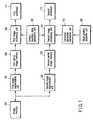
FIG. 1 is a block diagram showing the arrangement
of an image printing apparatus according to the first
embodiment of the present invention;
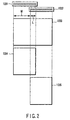
FIG. 2 is a view for explaining a partial image
segmentation method;
FIG. 3 is a view showing the positional relationship
between a printhead and a print medium;
FIGS. 4A and 4B are schematic views for explaining
a method of dividing an image signal for the first
printhead and second printhead and supplying the image
signals;
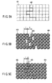
FIGS. 5A to 5C are views showing the state of a
joint before density nonuniformity correction;
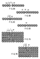
FIGS. 6A to 6D are views showing the state of
one line at the joint before and after density nonuniformity
correction;
FIGS. 7A and 7B are views showing the state of the
joint after density nonuniformity correction;
FIG. 8 is a block diagram for explaining details
of the second image processing unit;
FIGS. 9A to 9D are views showing concrete examples
of one line at the joint before and after density
nonuniformity correction;
FIG. 10 is a block diagram for explaining details
of the first image processing unit; and
FIG. 11 is a block diagram for explaining a quantization
error elimination method.
Best Mode for Carrying Out the Invention
A preferred embodiment of the present invention
will be described in detail below with reference to the
several views of the accompanying drawing.
(First Embodiment)
FIG. 1 is a block diagram for explaining the
first embodiment of the present invention. In FIG. 1,
an image memory 101 holds image data input to an
image printing apparatus. A first image segmentation
unit 102 and second image segmentation unit 103 are
respectively arranged for first and second printheads
111 and 112 each of which is formed from a plurality
of printing elements and prints an image in accordance
with an input signal. The first and second image
segmentation units 102 and 103 segment image data to
be printed by the printheads 111 and 112 from input
image data. A first partial image memory 104 and
second partial image memory 105 hold segmented partial
images.
A first image processing unit 106 and second
image processing unit 107 perform an image process for
improving the image quality at the joint between the
first and second printheads 111 and 112. Details of
this process will be described later. A division
boundary data generation unit 108 outputs information
on the switching positions of image data supplied to
the printheads 111 and 112. A head position detection
unit 109 detects the positional relationship (relative
positions) between the first and second printheads
111 and 112. A correction parameter calculation unit
110 calculates a correction parameter corresponding to
the detected positional relationship between the first
and second printheads 111 and 112.
An image input to the image printing apparatus is
first stored in the image memory 101. The first image
segmentation unit 102 and second image segmentation
unit 103 read out image data from the image memory 101,
and segment partial image data for forming images by
the first printhead 111 and second printhead 112. The
segmented image data are respectively stored in the
first partial image memory 104 and second partial image
memory 105.
The above-mentioned image segmentation process
will be explained in detail with reference to FIG. 2.
FIG. 2 shows the positional relationship between a
first printhead 1001 and a second printhead 1002. The
first printhead 1001 and second printhead 1002 partially
overlap each other.
Reference numeral 1003 denotes image data input
to the image printing apparatus. Reference numeral
1004 denotes first partial image data which is
segmented from the image data 1003 by the first image
segmentation unit (102 in FIG. 1) and stored in the
first partial image memory (104 in FIG. 1). Reference
numeral 1005 denotes second partial image data which is
segmented from the image data 1003 by the second image
segmentation unit (103 in FIG. 1) and stored in the
second partial image memory (105 in FIG. 1). The first
partial image data 1004 and second partial image data
1005 have a common portion (overlapping portion) by a
width L. The range within which the first printhead
(111 in FIG. 1) forms an image and the range within
which the second printhead (112 in FIG. 1) forms an
image are changed within the range of the width L for
each line.
Referring back to FIG. 1, the first image
processing unit 106 performs an image process for
improving the image quality at the joint between
printheads, for partial image data stored in the first
partial image memory 104. At this time, position
information output from the division boundary data
generation unit 108 is referred to as the shape of the
joint. The first partial image data having undergone
the image process is supplied to the first printhead
111 to form an image.
The second image processing unit 107 performs an
image process for improving the image quality at the
joint between printheads, for partial image data stored
in the second partial image memory 105. At this
time, position information output from the division
boundary data generation unit 108 is referred to as
the shape of the joint. In addition, a correction
parameter supplied from the correction parameter
calculation unit 110 is also referred to.
The head position detection unit 109 detects and
outputs a print dot interval δ at the joint as an
amount representing the positional relationship between
the first printhead 111 and the second printhead 112.
The correction parameter calculation unit 110 converts
the print dot interval δ at the joint, that is output
as a phase difference parameter from the head position
detection unit 109, into a correction parameter in
accordance with a conversion characteristic set in
advance on the basis of experiment or the like. The
correction parameter calculation unit 110 outputs the
correction parameter to the second image processing
unit 107.
The conversion characteristic held by the
correction parameter calculation unit 110 can be
obtained as follows. A printer in which the print
dot interval δ is set to a known value is prepared,
density nonuniformity correction (to be described
later) is performed for various correction parameter
values, and many print samples are formed. A print
sample whose density nonuniformity is improved most
is selected from these print samples. Such print
sample can be selected by density measurement of a
print sample or organoleptic test determined by the
subject. A correction parameter used to form the
selected print sample serves as the optimal value of
the correction parameter that corresponds to the set
print interval δ. In the same manner, the optimal
values of correction parameters are obtained for
various print dot intervals δ. As a result, a characteristic
curve representing the relationship between
the print dot interval δ and the optimal value of the
correction parameter is obtained. This curve is the
conversion characteristic.
FIG. 3 is a conceptual view showing the positional
relationship between the printhead and a print medium.
In FIG. 3, a first image processing unit 201 and second
image processing unit 202 perform an image process for
improving the image quality at the joint between
printheads, and supply image data to the printheads.
The first image processing unit 201 and second image
processing unit 202 correspond to 106 and 107 in
FIG. 1. Printheads 203 and 204 correspond to 111 and
112 in FIG. 1. The printheads 203 and 204 are formed
by linearly arranging many printing elements 205. For
example, in an inkjet printer, ink droplets are
discharged from the printing elements to form print
dots on a print medium 206.
When print dots are to be formed on the print
medium 206 by the printheads 203 and 204, the print
medium 206 moves from up to down relatively to the
printheads 203 and 204, as indicated by an arrow 214
in FIG. 3. As a result, the printheads 203 and 204
form images 207 and 208. The printheads 203 and 204
are arranged so that their printable regions partially
overlap each other. A joint 209 between the formed
images is made inconspicuous by an image process (to
be described later).
In multi-color printing, new printheads 212 and
213 can be added by a necessary number of colors. A
third image processing unit 210 and fourth image
processing unit 211 supply image data to the printheads
212 and 213, respectively.
A method of forming images at a joint by
printheads whose positions are not adjusted will be
described with reference to FIGS. 4A and 4B. In
FIGS. 4A and 4B, a first printhead 301 represents
the right end part of the printhead 203 in FIG. 3.
A second printhead 302 represents the left end part
of the printhead 204 in FIG. 3.
When the first printhead 301 and second printhead
302 are set with the positional relationship shown in
FIG. 4A, image data is supplied from the first image
processing unit 201 to the hatched printing elements up
to the printing element 303 of the first printhead 301.
Subsequent image data is supplied from the second image
processing unit 202 to the hatched printing elements
starting from the printing element 304 of the second
printhead 302. In this case, the print dot density
decreases at the joint unless density nonuniformity
correction is done. Stripe-like density nonuniformity
appears with low density at the joint.
When the first printhead 301 and second printhead
302 are set with the positional relationship shown in
FIG. 4B, image data is supplied from the first image
processing unit 201 to the hatched printing elements up
to the printing element 305 of the first printhead 301.
Subsequent image data is supplied from the second image
processing unit 202 to the hatched printing elements
starting from the printing element 306 of the second
printhead 302. In this case, the print dot density
increases at the joint unless density nonuniformity
correction is done. Stripe-like density nonuniformity
appears with high density at the joint.
Density nonuniformity correction will be described
in detail. As shown in FIGS. 4A and 4B, the interval
between printing elements is defined as one length
unit. In FIGS. 4A and 4B, the print dot interval δ
represents the phase difference along the line between
the printing elements of printheads (in FIG. 4A, the
printing element 303 of the first printhead 301 and
the printing element 304 of the second printhead 302,
and in FIG. 4B, the printing element 305 of the first
printhead 301 and the printing element 306 of the
second printhead 302).
It is effective to change the joint position not
uniformly but at random for each print line in order to
make the joint between printheads inconspicuous. This
method will be explained.
FIG. 5A is a conceptual view showing part of image
data at the joint between printheads. Each square
401 represents one pixel data. Reference numeral 402
denotes division boundary data representing a division
position used to divide image data for the first
printhead and second printhead and form images. The
division position changes along the printing element
array direction (line direction) for each print line,
as shown in FIG. 5A.
The division boundary data 402 is supplied from,
e.g., the division boundary data generation unit 108
in FIG. 1. The division boundary data 402 may be
stored in a ROM or the like in advance, or generated
by a program or the like. An input image is divided by
the first printhead and second printhead on the basis
of the division boundary data 402, and then formed.
FIGS. 5B and 5C show examples of an image formed
in correspondence with the division position of image
data shown in FIG. 5A. FIGS. 5B and 5C show examples
in which all pixels are printed. In practice, the
number of print dots and the density change in
accordance with image data.
FIG. 5B illustrates an example in which the print
dot interval δ at the joint is larger than 1 (1 < δ),
as shown in FIG. 4A. Horizontal hatch print dots 403
and the like are formed by the first printhead, and
tilt hatch print dots 404 and the like are formed by
the second printhead. Since the print dot interval δ
is larger than 1, portions 405 with large print dot
intervals exist on respective lines, and are recognized
as striped density nonuniformity with low density.
FIG. 5C illustrates an example in which the print
dot interval δ at the joint is smaller than 1 (δ < 1),
as shown in FIG. 4B. Similar to FIG. 5B, horizontal
hatch print dots 403 and the like are formed by the
first printhead, and tilt hatch print dots 404 and the
like are formed by the second printhead. Since the
print dot interval δ is smaller than 1, portions 406
with small print dot intervals exist on respective
lines, and are recognized as striped density nonuniformity
with high density.
FIG. 6A shows the uppermost line in FIG. 5B.
FIG. 6A shows a state before density nonuniformity
correction (to be described later) is performed.
Reference numeral 501 denotes a print dot formed by
the first printhead; and 502, a print dot formed by
the second printhead. FIG. 6B shows a state after the
image shown in FIG. 6A undergoes density nonuniformity
correction (to be described later). In FIG. 6B, the
print dots 501 and 502 are formed by the same printing
elements as those of the print dots 501 and 502 in
FIG. 6A. This correction adds a print dot 503 to
cancel density nonuniformity.
FIG. 6C shows the uppermost line in FIG. 5C.
FIG. 6C shows a state before density nonuniformity
correction (to be described later) is performed. A
print dot 504 is formed by the second printhead.
FIG. 6D shows a state after the image shown in FIG. 6C
undergoes density nonuniformity correction (to be
described later). In FIG. 6D, the print dot 504 is
formed by the same printing element as that of the
print dot 504 in FIG. 6C. This correction decreases
the density (density effect as the area ratio) of the
print dot 504 to cancel density nonuniformity.
As a result of density nonuniformity correction,
the image shown in FIG. 5B is corrected into one as
shown in FIG. 7A, and the image shown in FIG. 5C is
corrected into one as shown in FIG. 7B. In FIG. 7A,
density nonuniformity is canceled by adding small
print dots 601. In FIG. 7B, density nonuniformity is
canceled by decreasing the density of print dots 602.
Details of the second image processing unit
107 shown in FIG. 1 will be explained with reference
to FIG. 8. A range surrounded by a broken line 714
in FIG. 8 corresponds to the second image processing
unit 107.
A second partial image memory 701 in FIG. 8
corresponds to 105 in FIG. 1; a division boundary data
generation unit 703 in FIG. 8, to 108 in FIG. 1; a
correction parameter calculation unit 707 in FIG. 8, to
110 in FIG. 1; and a second printhead 712 in FIG. 8, to
112 in FIG. 1.
A branch unit 702 in FIG. 8 switches the image
process method for each pixel which forms image data.
A selection unit 704 selects output data in accordance
with the process in the branch unit 702. A data clear
unit 705 sets pixel data to 0 (unprinted). A multiplication
unit 706 multiplies a pixel signal branched from
the branch unit 702 by a correction parameter output
from the correction parameter calculation unit 707.
An integral part/decimal part separation unit
708 serving as a quantization unit separates a value
output from the multiplication unit 706 into an
integral part (a) and decimal part (b). A comparison
unit 709 compares the decimal part (b) and a uniform
random number r of 0 (inclusive) to 1 (exclusive) that
is generated by a random number generation unit 710,
and outputs 0 or 1 in accordance with the comparison
result. An addition unit 711 outputs the sum of the
integral part a and the comparison result of the
comparison unit 709. The random number generation unit
710 and comparison unit 709 form a quantized density
correction signal correction unit.
In this arrangement, pixel data which form image
data read out from the second partial image memory 701
are branched to three different processes by the branch
unit 702 in accordance with the coordinates in the
line direction. At this time, the division boundary
data generation unit 703 supplies division position
data Xn (n represents the number of lines) which
changes depending on the line number of a pixel to be
processed. Xn is the x-coordinate of a pixel left
adjacent to the division boundary when correction to
decrease the density in accordance with a correction
parameter output from the correction parameter calculation
unit 707 is performed, and the x-coordinate of a
pixel right adjacent to the division boundary in other
cases.
As for pixels left to Xn, data are sent to
the data clear unit 705, and after their values are
corrected to 0, sent to the selection unit 704.
As for pixels right to Xn, data are sent to the
selection unit 704 via a path 713 without changing
their values.
As for a pixel at Xn, data is sent to the
multiplication unit 706. The multiplication unit 706
multiplies the pixel data by a correction parameter
output from the correction parameter calculation unit
707, and sends the product to the integral part/decimal
part separation unit 708. The integral part/decimal
part separation unit 708 separates the input value
into an integral part a and decimal part b, and sends
the integral part a to the addition unit 711 and the
decimal part b to the comparison unit 709.
The comparison unit 709 compares the input decimal
part b and the random number r of 0 (inclusive) to 1.
(exclusive) output from the random number generation
unit 710. The comparison unit 709 outputs 1 when the
random number r is smaller than the decimal fraction b;
otherwise, 0. An output (0 or 1) from the comparison
unit 709 is sent to the addition unit 711. The addition
unit 711 adds the output and the integer a, and
sends the sum to the selection unit 704.
The selection unit 704 selects one output from
three image data branched and output by the branch
unit 702, and outputs the output value to the second
printhead 712.
The image processes will be explained in more
detail with reference to FIGS. 9A to 9D by exemplifying
a printer capable of expressing the density at eight
levels 0 to 7 for each print dot.
FIGS. 9A to 9D show the first line of image
data stored in the second partial image memory.
In FIGS. 9A to 9D, reference numeral 801 denotes a
division boundary between a pixel at which an image
is formed by the first printhead and a pixel at which
an image is formed by the second printhead. The
division boundary 801 corresponds to 402 in FIG. 5A.
A case in which the print dot interval δ at the
joint is larger than 1, i.e., density nonuniformity
with low density occurs, as shown in FIG. 5B, will be
explained with reference to FIGS. 9A and 9B.
When correction to increase the density of image
data shown in FIG. 9A is performed, X1 is so set as to
express a pixel left adjacent to the division boundary
801. Data of pixels having x-coordinates of 0 to X1-1
are sent to the data clear unit (705 in FIG. 8) via
the branch unit (702 in FIG. 8) where they are set to
0, and then sent to the selection unit (704 in FIG. 8).
As for a pixel having an x-coordinate of X1, data
is sent to the multiplication unit (706 in FIG. 8)
via the branch unit (702 in FIG. 8). In the example
of FIG. 9A, this pixel value is 4. Assuming that
the correction parameter output from the correction
parameter calculation unit (707 in FIG. 8) is 0.3
(correction amount representing addition of a print dot
having 30% of the density of the original pixel value),
an output from the multiplication unit (706 in FIG. 8)
is 4 × 0.3 = 1.2.
The value "1.2" is separated into an integral
part "1" and a decimal part "0.2" by the integral part/decimal
part separation unit (708 in FIG. 8). The
integral part "1" is sent to the addition unit (711
in FIG. 8), and the decimal part "0.2" is sent to the
comparison unit (709 in FIG. 8). Since the random
number generation unit (710 in FIG. 8) generates a
uniform random number of 0 (inclusive) to 1
(exclusive), the comparison unit (709 in FIG. 8)
compares the input decimal part "0.2" and the random
number and outputs 1 at a probability of 20% or 0 at
a probability of 80%.
The addition unit (711 in FIG. 8) adds 1 or 0
as an output from the comparison unit (709 in FIG. 8)
to the integral part "1". The addition unit (711 in
FIG. 8) outputs 2 at a probability of 20% or 1 at
a probability of 80% to the selection unit (704 in
FIG. 8). Signal values which can be input to the
printhead are only integer values of 0 to 7, and a
signal value of 0.2 as the decimal part cannot be
directly input. However, an image is formed from
many print dots, and thus even a probabilistic signal
process using a random number can reflect the signal
value of the decimal part in a formed image. An image
having a density more faithful to input image data can
be formed.
As for pixels having x-coordinates larger than X1,
data are sent from the branch unit (702 in FIG. 8) to
the selection unit (704 in FIG. 8) via the path (713 in
FIG. 8) without changing their values.
As a result of correction, image data shown in
FIG. 9A is corrected into one as shown in FIG. 9B.
In this case, N becomes 2 at a probability of 20% and
1 at a probability of 80%.
A case in which δ is smaller than 1, i.e.,
density nonuniformity with high density occurs, as
shown in FIG. 5C, will be explained with reference
to FIGS. 9C and 9D.
When correction to decrease the density of
image data shown in FIG. 9C is performed, X1 is so set
as to express a pixel right adjacent to the division
boundary 801.
Data of pixels having x-coordinates of 0 to X1-1
are sent to the data clear unit (705 in FIG. 8) via
the branch unit (702 in FIG. 8) where they are set to
0, and then sent to the selection unit (704 in FIG. 8).
Data of a pixel having an x-coordinate of X1
is sent to the multiplication unit (706 in FIG. 8)
via the branch unit (702 in FIG. 8). In the example
of FIG. 9C, this pixel value is 3. Assuming that
the correction parameter output from the correction
parameter calculation unit (707 in FIG. 8) is 0.7
(correction amount representing setting of a density
lower by 30% from the original pixel value), an
output from the multiplication unit (706 in FIG. 8)
is 3 × 0.7 = 2.1.
The value "2.1" is separated into an integral
part "2" and a decimal part "0.1" by the integral
part/decimal part separation unit (708 in FIG. 8).
The integral part "2" is sent to the addition unit (711
in FIG. 8), and the decimal part "0.1" is sent to the
comparison unit (709 in FIG. 8). Since the random
number generation unit (710 in FIG. 8) generates a
uniform random number of 0 (inclusive) to 1 (exclusive),
the comparison unit (709 in FIG. 8) compares
the input decimal part "0.1" and the random number
and outputs 1 at a probability of 10% or 0 at a
probability of 90%. The addition unit (711 in FIG. 8)
adds 1 or 0 as an output from the comparison unit (709
in FIG. 8) to the integral part "2". The addition unit
(711 in FIG. 8) outputs 3 at a probability of 10% or
2 at a probability of 90% to the selection unit (704
in FIG. 8).
As for pixels having x-coordinates larger than X1,
data are sent from the branch unit (702 in FIG. 8) to
the selection unit (704 in FIG. 8) via the path (713 in
FIG. 8) without changing their values.
As a result of correction, image data shown in
FIG. 9C is corrected into one as shown in FIG. 9D.
In this case, N becomes 3 at a probability of 10% and
2 at a probability of 90%.
The process method for the first line has been
described by exemplifying cases in which the correction
parameter is equal to or larger than 1 and smaller
than 1. This also applies to the second and subsequent
lines. Note that the Xn value is changed for each line
in accordance with the division boundary shape as shown
in FIG. 5A.
Details of the first image processing unit 106
shown in FIG. 1 will be explained with reference to
FIG. 10. A range surrounded by a broken line 908 in
FIG. 10 corresponds to the first image processing
unit 106 in FIG. 1. A first partial image memory 901
in FIG. 10 corresponds to 104 in FIG. 1; a division
boundary data generation unit 903 in FIG. 10, to 108 in
FIG. 1; and a first printhead 906 in FIG. 10, to 111 in
FIG. 1. A branch unit 902 has a function of switching
the image process method for each pixel which forms
image data. A selection unit 905 has a function of
selecting output data in accordance with the process
in the branch unit 902. A data clear unit 904 has a
function of setting pixel data to 0.
In this arrangement, pixel data which form image
data read out from the first partial image memory 901
undergo two different processes by the branch unit
902 in accordance with the coordinates in the line
direction. At this time, the division boundary data
generation unit 903 supplies, to the branch unit 902,
division position data Xn which changes depending on
the line number of a pixel to be processed.
Xn used in the first image processing unit 908 is
obtained by adding the number of pixels corresponding
to a width M shown in FIG. 2 to Xn used in the
second image processing unit (714 in FIG. 8). In the
first image processing unit 908, Xn is always the
x-coordinate of a pixel right adjacent to the division
boundary. As for pixels left to Xn, data are sent to
the selection unit 905 via a path 907 without changing
their values. As for a pixel at the Xn position and
pixels right to Xn, data are sent to the data clear
unit 904 where their values are corrected to 0, and
then sent to the selection unit 905. Consequently,
the values of pixels left to the division boundary do
not change, and those of pixels right to the division
boundary are changed to 0.
As described above, the present invention can
provide an image printing apparatus which reduces
density nonuniformity at the joint between printheads
and increases the image quality.
(Modification to First Embodiment)
In the above description, addition of a print
dot for density correction and level correction are
performed by only the second image processing unit.
However, these processes may be performed by both the
first image processing unit and second image processing
unit or by the first image processing unit and second
image processing unit alternately for each line. This
can effectively make the joint inconspicuous.
In the above description, the joint is made
inconspicuous by changing the joint position at random
for each line. However, the joint position may be
fixed or changed by another method when the joint
is originally inconspicuous because of the printing
characteristic or the like.
In the above description, a print dot for density
nonuniformity correction with a signal level which is
determined from a correction parameter corresponding
to the phase difference and a pixel adjacent to the
division boundary of a given line is formed at a position
adjacent to the division boundary of the same
line. However, a print dot may be formed at a position
adjacent to the division boundary of a peripheral line
such as the next line. Also in this case, almost the
same density correction effect can be attained.
In the above description, an integral part for
the same line is corrected in accordance with the value
of a decimal part output from the integral part/decimal
part separation unit. Alternatively, as shown in
FIG. 11, a decimal part output from the integral part/decimal
part separation unit 708 may be delayed via a
delay unit 715 and added by an addition unit 716 to the
result of the next process line from the multiplication
unit 706. Hence, a quantization error generated in the
current line is eliminated during the process of the
next line, and an image more faithful to the original
image is formed. In this manner, the quantized density
correction signal may be corrected not only by the
method (FIG. 8) of performing a process of correcting
a density correction signal after quantization but
also by the method (FIG. 11) of performing a process of
correcting a density correction signal before
quantization. The remaining arrangement in FIG. 11 is
the same as that in FIG. 8.
The above embodiment has been described on the
basis of an arrangement using hardware. However,
the same operation effects can be achieved even by
replacing the arrangement with an arrangement using
software which operates similarly to each hardware
arrangement.
The present invention can be effectively applied
especially to a full-line type printhead having a
length corresponding to the maximum width of a print
medium which is printable by the image printing
apparatus using a combination of printheads.
The present invention can also be effectively
applied to a print band boundary in a serial scan type
image printing apparatus which executes main scanning
of the printhead and sub-scanning of the print sheet.
A printhead discharge recovery unit, preliminary
auxiliary unit, or the like may be preferably added
to the arrangement of the image printing apparatus
according to the present invention in terms of further
stabilization of the effects of the present invention.
Examples of such unit are a printhead capping unit, a
cleaning unit, a pressure/suction unit, a preliminary
heating unit which performs heating using an electrothermal
transducer, a heating element, or a combination
of them, and a preliminary discharge unit which
performs discharge different from that for printing.
As for the type and number of mounted printheads,
plural printheads may be mounted in correspondence with
an ink of a single color, or plural printheads may be
mounted respectively in correspondence with inks of
different print colors or densities. In other words,
the present invention can also be effectively applied
to an apparatus not only having, as the print mode of
the image printing apparatus, a print mode using only a
main color such as black, but also having at least one
of a multicolor print mode using different colors or a
full-color print mode using a color mixture by an
integral printhead structure or a combination of
printheads.
In addition to liquid ink, the image printing
apparatus may employ ink which solidifies at room
temperature or lower temperatures and softens or
liquefies at room temperature or by heating. The
ink temperature may be adjusted in use. In order
to prevent ink evaporation, the image printing apparatus
may use ink which is solid in a normal state
and liquefies by heating. In any case, the present
invention can be effectively applied to an image
printing apparatus which discharges liquid ink in
accordance with a print signal or uses ink of a nature
that has already started solidifying when it reaches
a print medium.
The form of the image printing apparatus according
to the present invention may be the form of an image
output terminal for an information processing device
such as a computer, the form of a copying machine
combined with a scanner or the like, or the form of a
facsimile apparatus having a transmission/reception
function.
Industrial Applicability
The present invention can provide an image
printing apparatus which can reduce density
nonuniformity at the joint between printheads and
thereby increase the image quality.