EP1479431A2 - An exhaust gas purifying apparatus and method of using the same - Google Patents
An exhaust gas purifying apparatus and method of using the same Download PDFInfo
- Publication number
- EP1479431A2 EP1479431A2 EP04011990A EP04011990A EP1479431A2 EP 1479431 A2 EP1479431 A2 EP 1479431A2 EP 04011990 A EP04011990 A EP 04011990A EP 04011990 A EP04011990 A EP 04011990A EP 1479431 A2 EP1479431 A2 EP 1479431A2
- Authority
- EP
- European Patent Office
- Prior art keywords
- adsorbent
- exhaust gas
- plasma
- plasma reactor
- gas purifying
- Prior art date
- Legal status (The legal status is an assumption and is not a legal conclusion. Google has not performed a legal analysis and makes no representation as to the accuracy of the status listed.)
- Withdrawn
Links
Images

Classifications
-
- F—MECHANICAL ENGINEERING; LIGHTING; HEATING; WEAPONS; BLASTING
- F01—MACHINES OR ENGINES IN GENERAL; ENGINE PLANTS IN GENERAL; STEAM ENGINES
- F01N—GAS-FLOW SILENCERS OR EXHAUST APPARATUS FOR MACHINES OR ENGINES IN GENERAL; GAS-FLOW SILENCERS OR EXHAUST APPARATUS FOR INTERNAL-COMBUSTION ENGINES
- F01N3/00—Exhaust or silencing apparatus having means for purifying, rendering innocuous, or otherwise treating exhaust
- F01N3/08—Exhaust or silencing apparatus having means for purifying, rendering innocuous, or otherwise treating exhaust for rendering innocuous
- F01N3/0807—Exhaust or silencing apparatus having means for purifying, rendering innocuous, or otherwise treating exhaust for rendering innocuous by using absorbents or adsorbents
- F01N3/0828—Exhaust or silencing apparatus having means for purifying, rendering innocuous, or otherwise treating exhaust for rendering innocuous by using absorbents or adsorbents characterised by the absorbed or adsorbed substances
- F01N3/0835—Hydrocarbons
-
- B—PERFORMING OPERATIONS; TRANSPORTING
- B01—PHYSICAL OR CHEMICAL PROCESSES OR APPARATUS IN GENERAL
- B01D—SEPARATION
- B01D53/00—Separation of gases or vapours; Recovering vapours of volatile solvents from gases; Chemical or biological purification of waste gases, e.g. engine exhaust gases, smoke, fumes, flue gases, aerosols
- B01D53/34—Chemical or biological purification of waste gases
- B01D53/92—Chemical or biological purification of waste gases of engine exhaust gases
-
- B—PERFORMING OPERATIONS; TRANSPORTING
- B01—PHYSICAL OR CHEMICAL PROCESSES OR APPARATUS IN GENERAL
- B01D—SEPARATION
- B01D53/00—Separation of gases or vapours; Recovering vapours of volatile solvents from gases; Chemical or biological purification of waste gases, e.g. engine exhaust gases, smoke, fumes, flue gases, aerosols
- B01D53/34—Chemical or biological purification of waste gases
- B01D53/92—Chemical or biological purification of waste gases of engine exhaust gases
- B01D53/94—Chemical or biological purification of waste gases of engine exhaust gases by catalytic processes
- B01D53/9404—Removing only nitrogen compounds
- B01D53/9409—Nitrogen oxides
- B01D53/9431—Processes characterised by a specific device
-
- F—MECHANICAL ENGINEERING; LIGHTING; HEATING; WEAPONS; BLASTING
- F01—MACHINES OR ENGINES IN GENERAL; ENGINE PLANTS IN GENERAL; STEAM ENGINES
- F01N—GAS-FLOW SILENCERS OR EXHAUST APPARATUS FOR MACHINES OR ENGINES IN GENERAL; GAS-FLOW SILENCERS OR EXHAUST APPARATUS FOR INTERNAL-COMBUSTION ENGINES
- F01N13/00—Exhaust or silencing apparatus characterised by constructional features
- F01N13/009—Exhaust or silencing apparatus characterised by constructional features having two or more separate purifying devices arranged in series
-
- F—MECHANICAL ENGINEERING; LIGHTING; HEATING; WEAPONS; BLASTING
- F01—MACHINES OR ENGINES IN GENERAL; ENGINE PLANTS IN GENERAL; STEAM ENGINES
- F01N—GAS-FLOW SILENCERS OR EXHAUST APPARATUS FOR MACHINES OR ENGINES IN GENERAL; GAS-FLOW SILENCERS OR EXHAUST APPARATUS FOR INTERNAL-COMBUSTION ENGINES
- F01N13/00—Exhaust or silencing apparatus characterised by constructional features
- F01N13/009—Exhaust or silencing apparatus characterised by constructional features having two or more separate purifying devices arranged in series
- F01N13/0097—Exhaust or silencing apparatus characterised by constructional features having two or more separate purifying devices arranged in series the purifying devices are arranged in a single housing
-
- F—MECHANICAL ENGINEERING; LIGHTING; HEATING; WEAPONS; BLASTING
- F01—MACHINES OR ENGINES IN GENERAL; ENGINE PLANTS IN GENERAL; STEAM ENGINES
- F01N—GAS-FLOW SILENCERS OR EXHAUST APPARATUS FOR MACHINES OR ENGINES IN GENERAL; GAS-FLOW SILENCERS OR EXHAUST APPARATUS FOR INTERNAL-COMBUSTION ENGINES
- F01N3/00—Exhaust or silencing apparatus having means for purifying, rendering innocuous, or otherwise treating exhaust
- F01N3/08—Exhaust or silencing apparatus having means for purifying, rendering innocuous, or otherwise treating exhaust for rendering innocuous
- F01N3/0807—Exhaust or silencing apparatus having means for purifying, rendering innocuous, or otherwise treating exhaust for rendering innocuous by using absorbents or adsorbents
- F01N3/0814—Exhaust or silencing apparatus having means for purifying, rendering innocuous, or otherwise treating exhaust for rendering innocuous by using absorbents or adsorbents combined with catalytic converters, e.g. NOx absorption/storage reduction catalysts
-
- F—MECHANICAL ENGINEERING; LIGHTING; HEATING; WEAPONS; BLASTING
- F01—MACHINES OR ENGINES IN GENERAL; ENGINE PLANTS IN GENERAL; STEAM ENGINES
- F01N—GAS-FLOW SILENCERS OR EXHAUST APPARATUS FOR MACHINES OR ENGINES IN GENERAL; GAS-FLOW SILENCERS OR EXHAUST APPARATUS FOR INTERNAL-COMBUSTION ENGINES
- F01N3/00—Exhaust or silencing apparatus having means for purifying, rendering innocuous, or otherwise treating exhaust
- F01N3/08—Exhaust or silencing apparatus having means for purifying, rendering innocuous, or otherwise treating exhaust for rendering innocuous
- F01N3/0807—Exhaust or silencing apparatus having means for purifying, rendering innocuous, or otherwise treating exhaust for rendering innocuous by using absorbents or adsorbents
- F01N3/0828—Exhaust or silencing apparatus having means for purifying, rendering innocuous, or otherwise treating exhaust for rendering innocuous by using absorbents or adsorbents characterised by the absorbed or adsorbed substances
- F01N3/0842—Nitrogen oxides
-
- B—PERFORMING OPERATIONS; TRANSPORTING
- B01—PHYSICAL OR CHEMICAL PROCESSES OR APPARATUS IN GENERAL
- B01D—SEPARATION
- B01D2259/00—Type of treatment
- B01D2259/80—Employing electric, magnetic, electromagnetic or wave energy, or particle radiation
- B01D2259/818—Employing electrical discharges or the generation of a plasma
-
- F—MECHANICAL ENGINEERING; LIGHTING; HEATING; WEAPONS; BLASTING
- F01—MACHINES OR ENGINES IN GENERAL; ENGINE PLANTS IN GENERAL; STEAM ENGINES
- F01N—GAS-FLOW SILENCERS OR EXHAUST APPARATUS FOR MACHINES OR ENGINES IN GENERAL; GAS-FLOW SILENCERS OR EXHAUST APPARATUS FOR INTERNAL-COMBUSTION ENGINES
- F01N2240/00—Combination or association of two or more different exhaust treating devices, or of at least one such device with an auxiliary device, not covered by indexing codes F01N2230/00 or F01N2250/00, one of the devices being
- F01N2240/22—Combination or association of two or more different exhaust treating devices, or of at least one such device with an auxiliary device, not covered by indexing codes F01N2230/00 or F01N2250/00, one of the devices being a condensation chamber
-
- F—MECHANICAL ENGINEERING; LIGHTING; HEATING; WEAPONS; BLASTING
- F01—MACHINES OR ENGINES IN GENERAL; ENGINE PLANTS IN GENERAL; STEAM ENGINES
- F01N—GAS-FLOW SILENCERS OR EXHAUST APPARATUS FOR MACHINES OR ENGINES IN GENERAL; GAS-FLOW SILENCERS OR EXHAUST APPARATUS FOR INTERNAL-COMBUSTION ENGINES
- F01N2240/00—Combination or association of two or more different exhaust treating devices, or of at least one such device with an auxiliary device, not covered by indexing codes F01N2230/00 or F01N2250/00, one of the devices being
- F01N2240/28—Combination or association of two or more different exhaust treating devices, or of at least one such device with an auxiliary device, not covered by indexing codes F01N2230/00 or F01N2250/00, one of the devices being a plasma reactor
-
- F—MECHANICAL ENGINEERING; LIGHTING; HEATING; WEAPONS; BLASTING
- F01—MACHINES OR ENGINES IN GENERAL; ENGINE PLANTS IN GENERAL; STEAM ENGINES
- F01N—GAS-FLOW SILENCERS OR EXHAUST APPARATUS FOR MACHINES OR ENGINES IN GENERAL; GAS-FLOW SILENCERS OR EXHAUST APPARATUS FOR INTERNAL-COMBUSTION ENGINES
- F01N2570/00—Exhaust treating apparatus eliminating, absorbing or adsorbing specific elements or compounds
- F01N2570/22—Water or humidity
Definitions
- the present invention relates to an apparatus for purifying exhaust gas emitted from internal combustion engine and, in particular, to an apparatus for purifying NO x (nitrogen oxide) emitted from a motor vehicle.
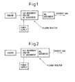
- An exhaust gas purifying apparatus comprises a plasma reactor containing at least one of a H 2 O adsorbent and a HC (hydrocarbon) adsorbent; and a NO x adsorbent located downstream of said plasma reactor.
- the plasma reactor used for the exhaust gas purifying apparatus of the present invention may be any kind of plasma reactor which allows the exhaust gas therethrough, e.g. the plasma reactor shown in Figs. 3a and 3b.
- Fig. 3a shows a perspective view
- Fig. 3b shows a side sectional view of the plasma reactor.
Landscapes
- Engineering & Computer Science (AREA)
- Chemical & Material Sciences (AREA)
- Combustion & Propulsion (AREA)
- General Engineering & Computer Science (AREA)
- Mechanical Engineering (AREA)
- Chemical Kinetics & Catalysis (AREA)
- Health & Medical Sciences (AREA)
- General Chemical & Material Sciences (AREA)
- Oil, Petroleum & Natural Gas (AREA)
- Analytical Chemistry (AREA)
- Environmental & Geological Engineering (AREA)
- Biomedical Technology (AREA)
- Exhaust Gas After Treatment (AREA)
- Treating Waste Gases (AREA)
- Exhaust Gas Treatment By Means Of Catalyst (AREA)
Abstract
Description
| NO → NO2 conversion ratio | ||
| no plasma | plasma | |
| no H2O adsorbent | 0 | 18 |
| H2O adsorbent | 1 | 40 |
| NO → NO2 conversion ratio | ||
| no plasma | plasma | |
| no HC adsorbent | 0 | 29 |
| | 10 | 71 |
Claims (12)
- An exhaust gas purifying apparatus comprising;
a plasma reactor containing at least one of a H2O adsorbent and a HC adsorbent, and
a NOx adsorbent located downstream of said plasma reactor. - The exhaust gas purifying apparatus according to claim 1 wherein said NOx adsorbent has NOx purifying catalyst.
- The exhaust gas purifying apparatus according to claim 1 comprising a NOx purifying catalyst located downstream of the said NOx adsorbent.
- The exhaust gas purifying apparatus according to claim 1 wherein said at least one of a H2O adsorbent and a HC adsorbent is selected from the group consisting of alumina, silica, zeolite, zirconia and meso-porous silica, and combinations thereof.
- The exhaust gas purifying apparatus according to claim 1 wherein said NOx adsorbent is selected from the group consisting of zirconia and ceria, and a combination thereof.
- A method for using the exhaust gas purifying apparatus according to claim 2 wherein a plasma is generated in the plasma reactor only when the temperature of said NOx purifying catalyst is lower than a predetermined temperature.
- A method for using the exhaust gas purifying apparatus according to claim 3 wherein a plasma is generated in the plasma reactor only when the temperature of said NOx purifying catalyst is lower than a predetermined temperature.
- An exhaust gas purifying apparatus comprising;
a plasma reactor containing at least one of a H2O adsorbent and a HC adsorbent, and a NOx adsorbent, and
a NOx adsorbent located downstream of said plasma reactor. - The exhaust gas purifying apparatus according to claim 8 wherein said NOx adsorbent has NOx purifying catalyst.
- The exhaust gas purifying apparatus according to claim 8 comprising a NOx purifying catalyst located downstream of the said NOx adsorbent.
- A method for using the exhaust gas purifying apparatus according to claim 9 wherein a plasma is generated in the plasma reactor only when the temperature of said NOx purifying catalyst is lower than a predetermined temperature.
- A method for using the exhaust gas purifying apparatus according to claim 10 wherein a plasma is generated in the plasma reactor only when the temperature of said NOx purifying catalyst is lower than a predetermined temperature.
Applications Claiming Priority (2)
| Application Number | Priority Date | Filing Date | Title |
|---|---|---|---|
| JP2003142332A JP2004346772A (en) | 2003-05-20 | 2003-05-20 | Exhaust gas purification apparatus and method |
| JP2003142332 | 2003-05-20 |
Publications (2)
| Publication Number | Publication Date |
|---|---|
| EP1479431A2 true EP1479431A2 (en) | 2004-11-24 |
| EP1479431A3 EP1479431A3 (en) | 2005-11-09 |
Family
ID=33095416
Family Applications (1)
| Application Number | Title | Priority Date | Filing Date |
|---|---|---|---|
| EP04011990A Withdrawn EP1479431A3 (en) | 2003-05-20 | 2004-05-19 | An exhaust gas purifying apparatus and method of using the same |
Country Status (3)
| Country | Link |
|---|---|
| US (1) | US7181903B2 (en) |
| EP (1) | EP1479431A3 (en) |
| JP (1) | JP2004346772A (en) |
Families Citing this family (9)
| Publication number | Priority date | Publication date | Assignee | Title |
|---|---|---|---|---|
| US7412872B2 (en) * | 2005-03-31 | 2008-08-19 | Intel Corporation | Process for screening outgas emissions in semiconductor processing |
| JP2009156063A (en) * | 2007-12-25 | 2009-07-16 | Toyota Industries Corp | Exhaust gas treatment system of internal combustion engine |
| JP4941284B2 (en) * | 2007-12-28 | 2012-05-30 | 株式会社豊田自動織機 | Exhaust gas treatment system for internal combustion engine |
| DE102009041092A1 (en) * | 2009-09-14 | 2011-03-24 | Emitec Gesellschaft Für Emissionstechnologie Mbh | Exhaust treatment device with two honeycomb bodies for generating an electrical potential |
| US8984870B2 (en) * | 2011-02-22 | 2015-03-24 | GM Global Technology Operations LLC | Low temperature NOx storage system for lean exhaust aftertreatment |
| US8491860B2 (en) | 2011-08-17 | 2013-07-23 | Ford Global Technologies, Llc | Methods and systems for an engine emission control system |
| US8920756B2 (en) * | 2012-05-07 | 2014-12-30 | GM Global Technology Operations LLC | Silver promoted close-coupled NOx absorber |
| RU2689020C1 (en) | 2018-10-30 | 2019-05-23 | Радченко Виталий Анатольевич | Device for the internal combustion engines emissions cleaning of the nitrogen oxides using the non-equilibrium low-temperature plasma and the absorber |
| JP7224876B2 (en) * | 2018-11-29 | 2023-02-20 | ダイハツ工業株式会社 | exhaust system |
Family Cites Families (15)
| Publication number | Priority date | Publication date | Assignee | Title |
|---|---|---|---|---|
| JP3277698B2 (en) | 1994-06-29 | 2002-04-22 | 日産自動車株式会社 | Exhaust gas purification device for internal combustion engine |
| US5746984A (en) * | 1996-06-28 | 1998-05-05 | Low Emissions Technologies Research And Development Partnership | Exhaust system with emissions storage device and plasma reactor |
| US5711147A (en) * | 1996-08-19 | 1998-01-27 | The Regents Of The University Of California | Plasma-assisted catalytic reduction system |
| US6038854A (en) * | 1996-08-19 | 2000-03-21 | The Regents Of The University Of California | Plasma regenerated particulate trap and NOx reduction system |
| GB9726713D0 (en) * | 1997-12-19 | 1998-02-18 | Aea Technology Plc | Gas purification |
| DE19819372C2 (en) * | 1998-04-30 | 2000-03-02 | Degussa | Process for reducing the nitrogen oxide content of the exhaust gases of an internal combustion engine |
| US6560958B1 (en) * | 1998-10-29 | 2003-05-13 | Massachusetts Institute Of Technology | Emission abatement system |
| US6176078B1 (en) * | 1998-11-13 | 2001-01-23 | Engelhard Corporation | Plasma fuel processing for NOx control of lean burn engines |
| DE19903533A1 (en) * | 1999-01-29 | 2000-08-10 | Degussa | Process for the selective catalytic reduction of nitrogen oxides in oxygen-containing exhaust gases |
| GB9924999D0 (en) * | 1999-10-22 | 1999-12-22 | Aea Technology Plc | Reactor for the plasma treatment of gases |
| JP2001182525A (en) | 1999-12-22 | 2001-07-06 | Toyota Central Res & Dev Lab Inc | NOx purification method and apparatus under plasma |
| DE10021693C2 (en) * | 2000-05-04 | 2003-08-07 | Siemens Ag | Process and device for exhaust gas purification |
| JP2002155731A (en) | 2000-11-21 | 2002-05-31 | Toyota Motor Corp | Exhaust gas purification device for internal combustion engine |
| US6887438B2 (en) * | 2000-12-21 | 2005-05-03 | Delphi Technologies, Inc. | NOx control |
| JP2002221027A (en) | 2001-01-25 | 2002-08-09 | Denso Corp | Exhaust gas purification device for internal combustion engine |
-
2003
- 2003-05-20 JP JP2003142332A patent/JP2004346772A/en active Pending
-
2004
- 2004-05-14 US US10/845,161 patent/US7181903B2/en not_active Expired - Fee Related
- 2004-05-19 EP EP04011990A patent/EP1479431A3/en not_active Withdrawn
Also Published As
| Publication number | Publication date |
|---|---|
| JP2004346772A (en) | 2004-12-09 |
| US7181903B2 (en) | 2007-02-27 |
| EP1479431A3 (en) | 2005-11-09 |
| US20040231321A1 (en) | 2004-11-25 |
Similar Documents
| Publication | Publication Date | Title |
|---|---|---|
| KR101114167B1 (en) | Apparatus and method for regenerating catalyst for purifying exhaust gas | |
| US7521031B2 (en) | Method and apparatus for treating exhaust gas | |
| US5746984A (en) | Exhaust system with emissions storage device and plasma reactor | |
| US6374595B1 (en) | Plasma-assisted catalytic storage reduction system | |
| US6852200B2 (en) | Non-thermal plasma reactor gas treatment system | |
| US6887438B2 (en) | NOx control | |
| JP4112740B2 (en) | Method for reducing the nitrogen oxide content of exhaust gas from internal combustion engines | |
| US7181903B2 (en) | Exhaust gas purifying apparatus and method of using the same | |
| US20040234430A1 (en) | Exhaust gas purifying apparatus and method of using the same | |
| JP4114581B2 (en) | Exhaust purification device | |
| EP1236497B1 (en) | Exhaust gas processing system and its use | |
| Rajanikanth et al. | Pulsed electrical discharges assisted by dielectric pellets/catalysts for diesel engine exhaust treatment | |
| JP4591164B2 (en) | Exhaust gas purification method and exhaust gas purification device | |
| JP2001162134A (en) | Exhaust gas purification method and exhaust gas purification device | |
| JP2004181418A (en) | NOx purifying plasma assisted catalytic converter and exhaust gas purifying method | |
| CN105715336A (en) | Exhaust gas pose-processing system and method for internal combustion engine | |
| JP4635693B2 (en) | Exhaust gas purification method and exhaust gas purification device | |
| JP2004058029A (en) | Energy-saving electrochemical reaction system and activation method thereof | |
| JP2004041965A (en) | Nitrogen oxide removal system | |
| JP2002210366A (en) | Plasma assisted catalyst for NOx purification | |
| Rajanikanth et al. | Non-conventional plasma assisted catalysts for diesel exhaust treatment: a case study | |
| Matsui et al. | Simultaneous removal of NOx and particles from diesel engine exhaust using plasma and oxidative catalyst | |
| JP2005061247A (en) | Exhaust purification equipment | |
| JP2004068797A (en) | Removing equipment for nitrogen oxides | |
| JPH09253444A (en) | Noxious gas removing device and method for removing the gas |
Legal Events
| Date | Code | Title | Description |
|---|---|---|---|
| PUAI | Public reference made under article 153(3) epc to a published international application that has entered the european phase |
Free format text: ORIGINAL CODE: 0009012 |
|
| 17P | Request for examination filed |
Effective date: 20040519 |
|
| AK | Designated contracting states |
Kind code of ref document: A2 Designated state(s): AT BE BG CH CY CZ DE DK EE ES FI FR GB GR HU IE IT LI LU MC NL PL PT RO SE SI SK TR |
|
| AX | Request for extension of the european patent |
Extension state: AL HR LT LV MK |
|
| PUAL | Search report despatched |
Free format text: ORIGINAL CODE: 0009013 |
|
| AK | Designated contracting states |
Kind code of ref document: A3 Designated state(s): AT BE BG CH CY CZ DE DK EE ES FI FR GB GR HU IE IT LI LU MC NL PL PT RO SE SI SK TR |
|
| AX | Request for extension of the european patent |
Extension state: AL HR LT LV MK |
|
| AKX | Designation fees paid |
Designated state(s): DE FR GB |
|
| STAA | Information on the status of an ep patent application or granted ep patent |
Free format text: STATUS: THE APPLICATION HAS BEEN WITHDRAWN |
|
| 18W | Application withdrawn |
Effective date: 20070704 |