EP1479228B1 - Agc detector and method for agc detecting - Google Patents
Agc detector and method for agc detecting Download PDFInfo
- Publication number
- EP1479228B1 EP1479228B1 EP03702843A EP03702843A EP1479228B1 EP 1479228 B1 EP1479228 B1 EP 1479228B1 EP 03702843 A EP03702843 A EP 03702843A EP 03702843 A EP03702843 A EP 03702843A EP 1479228 B1 EP1479228 B1 EP 1479228B1
- Authority
- EP
- European Patent Office
- Prior art keywords
- pulses
- region
- period
- gating
- porch region
- Prior art date
- Legal status (The legal status is an assumption and is not a legal conclusion. Google has not performed a legal analysis and makes no representation as to the accuracy of the status listed.)
- Expired - Lifetime
Links
Images


Classifications
-
- H—ELECTRICITY
- H04—ELECTRIC COMMUNICATION TECHNIQUE
- H04N—PICTORIAL COMMUNICATION, e.g. TELEVISION
- H04N5/00—Details of television systems
- H04N5/44—Receiver circuitry for the reception of television signals according to analogue transmission standards
- H04N5/52—Automatic gain control
- H04N5/53—Keyed automatic gain control
Definitions
- the present invention relates to an AGC (automatic gain control) detector device for television receivers displaying video pictures consisting of a plurality of horizontal lines to be built up successively, comprising
- the present invention relates to a method for AGC detecting for television receivers displaying video pictures consisting of a plurality of horizontal lines to be built up successively, comprising the steps of
- a so-called digital black level (back porch) automatic gain control for television receivers is already known, wherein the horizontal line frequency is used to determine the level at the back porch region of a video output signal. This is compared to a reference level for black, and the difference is the resulting loop gain error. The resulting loop gain error is integrated, digital/analog-converted and finally applied to an analog AGC amplifier via an analog non-critical first-order post filter in order to keep the video output voltage constant.
- the video output voltage is affected by a negative effect called "airplane flutter" which results from changing multi-path reception.
- airplane flutter a negative effect which results from changing multi-path reception.
- the video output voltage is not kept on a constant level any time, but varying, and sometimes the video output voltage is completely distorted. This negative effect leads to a considerable reduction of picture and sound quality.
- an AGC detector device for television receivers displaying video pictures consisting of a plurality of horizontal lines to be built up successively using gating pulses for AGC, comprising
- a method for AGC detecting for television receivers displaying video pictures consisting of a plurality of horizontal lines to be built up successively using gating pulses for AGC comprising the steps of
- the present invention provides a new AGC detector device and a new method for AGC detecting which are fast enough to follow airplane flutter reception conditions with still good picture and sound impression.
- This is achieved by gating the serration pulse region with multiple (in particular three) time shifted horizontal sync pulses and by taking the error signal from the front porch measurement.
- the gating is changed from back porch to front porch during the serration pulse region of the vertical sync period which lasts 19 to 25 line periods depending on the television standard.
- an advantage of the present invention is that television receivers create good picture and sound impression even under high velocity e.g. in cars. So, the present invention is in particular convenient for mobile television.
- first means for detecting the occurrence of the back porch region of the horizontal sync pulses and second means for detecting the occurrence of the front porch region of the horizontal sync pulses, wherein said first and second detecting means are coupled to said shifting means and at least said first detecting means is coupled to said adjusting means.
- the device is a digital AGC detector device. Namely, the change of the gating from back porch to front porch during the serration pulse region can be done easily because it can happen in the digital domain.
- the present invention can be provided for analog television receivers.
- the gating pulses generating means comprises a PLL circuit which can be a horizontal PLL circuit, and the gating pulses generating means can further comprise a vertical integrator.
- the gating pulses generating means can further comprise a vertical integrator.
- the gating pulses can be also derived from a conventional sync slicer.
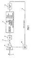
- FIG. 1 A schematic block diagram of a preferred embodiment of a gated digital AGC (automatic gain control) circuit for analog television receivers is shown in Figure 1 .
- the shown circuit comprises an input terminal 2 for inputting an IF (intermediate frequency) signal.
- the input terminal 2 is connected to an input of a controllable analog AGC amplifier 4 whose output is coupled to an output terminal 6 for outputting the gained IF signal.
- the output of the analog AGC amplifier 4 is further connected to an input of an analog/digital-converter 8 whose output is coupled to an input of a digital signal processing device 10.
- An output of the digital signal processing device 10 is connected to an input of a bit stream digital/analog-converter 12 whose output is coupled via a feed back loop 14 to an input of an analog non-critical first-order post filter 16.
- the output signal of the post filter 16 is a control signal for controlling the AGC amplifier 4.
- a CVBS color video blanking sync
- the horizontal line frequency is derived from the CVBS signal and is used to determine the level at the back porch region of the CVBS signal. This level is compared to a reference level for black.
- a H-PLL circuit is provided in the digital signal processing device 10. The difference between the level at the back porch region of the CVBS signal and the reference level for black is the resulting loop gain error which is integrated in the digital signal processing device 10. So, gating pulses are produced by being supplied from a H-PLL and V-INTEGRATOR.
- VCR video cassette recorder
- STB set top box
- some gating pulses are derived from a conventional sync slicer which is also included in the digital signal processing device 10.
- a copy protection e.g. MACROVISION
- some gating pulses are blanked.
- a corresponding flag is set in the digital signal processing device 10.
- a multi-bit AGC error signal is outputted from the digital signal processing device 10, converted into an analog signal by the digital/analog-converter 12 and applied as an AGC error signal to the AGC amplifier 4 via the feed back loop 14 and the post filter 16 in order to keep the output signal of the AGC amplifier 4 constant.
- the occurrence of the gating pulses is synchronized with the back porch region of the horizontal sync pulses.
- a critical time period is the serration pulse region forming part of the vertical sync period wherein serration pulses occur which have no back porch region.
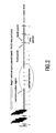
- Figure 2 it is shown the waveform of the CVBS signal without influence of airplane flutter and in particular the waveform of the CVBS signal during the beginning of the vertical sync period including the serration pulse region.
- the digital signal processing device 10 changes the gating from back porch to front porch during the serration pulse region. So, the serration pulse region is gated with three time-shifted horizontal sync pulses by taking the error signal from the front porch measurement. In the digital domain this can be done with high accuracy. So, the AGC loop stays closed all the time and can thus function with good performance.
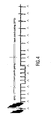
- Figure 4 shows the waveform of the CVBS signal under the occurrence of airplane flutter (80% AM, 80 Hz) and further showing the gaiting pulses indicated as upright arrows below the CVBS waveform, wherein front porch gating is carried out during the serration pulse region.
- Figure 5 shows more details of the timing instants for the sync and gating pulses with reference to Figure 4 .
- Figure 5 shows in more detail that during back porch gating the gating pulses occur a time distance ⁇ T1 after the occurrence of the sync pulses, whereas during the serration pulse region when front porch gating is carried out the gating pulses occur a time distance ⁇ T2 before the occurrence of the sync pulses. So, according to Figure 5 the gating pulses occur earlier by a time interval corresponding to the total time distance ⁇ T1 + ⁇ T2 to hit the front porch regions during the serration pulse region.
- Figure 6 shows an alternative method of changing from back porch gating to front porch gating wherein the gating pulses are delayed by a time interval ⁇ T3 behind the occurrence of the sync pulses to hit the next front porch region and the subsequent front porch regions during the serration pulse region. So, in the situation of Figure 6 , the gating pulses occur later by a time interval corresponding to the time distance ⁇ T3 - ⁇ T1 between the first back porch region and the next front porch region within the serration pulse region so as to change from back porch gating to front porch gating. With respect thereto, it should be added that apart from the different kind of changing from back porch gating to front porch gating, the situation of Figure 6 is the same as that of Figures 4 and 5 .
- the digital signal processing device 10 ( Figure 1 ) includes inter alia the function of an AGC detector.
Landscapes
- Engineering & Computer Science (AREA)
- Multimedia (AREA)
- Signal Processing (AREA)
- Television Receiver Circuits (AREA)
- Burglar Alarm Systems (AREA)
- Glass Compositions (AREA)
Abstract
Description
- The present invention relates to an AGC (automatic gain control) detector device for television receivers displaying video pictures consisting of a plurality of horizontal lines to be built up successively, comprising
- means for inputting a CVBS (color video blanking sync) signal which includes horizontal sync pulses having a front porch region and a back porch region and occurring once a horizontal line during a horizontal sync period when generating a current video picture, and further includes vertical sync pulses occurring during a vertical sync period before the generation of a new video picture and including serration pulses which occur during a serration pulse region being part of the vertical sync period,
- means for generating gating pulses having a period which is equal to the line period of the horizontal sync pulses, and
- means for adjusting said gating pulses such that they occur at the back porch region of the horizontal sync pulses.
- Further, the present invention relates to a method for AGC detecting for television receivers displaying video pictures consisting of a plurality of horizontal lines to be built up successively, comprising the steps of
- inputting a CVBS signal which includes horizontal sync pulses having a front porch region and a back porch region and occurring once a horizontal line during a horizontal sync period when generating a current video picture, and further includes vertical sync pulses occurring during a vertical sync period before the generation of a new video picture and including serration pulses which occur during a serration pulse region being part of the vertical sync period,
- generating gating pulses having a period which is equal to the line period of the horizontal sync pulses, and
- adjusting said gating pulses such that they occur at the back porch region of the horizontal sync pulses.
- A so-called digital black level (back porch) automatic gain control for television receivers is already known, wherein the horizontal line frequency is used to determine the level at the back porch region of a video output signal. This is compared to a reference level for black, and the difference is the resulting loop gain error. The resulting loop gain error is integrated, digital/analog-converted and finally applied to an analog AGC amplifier via an analog non-critical first-order post filter in order to keep the video output voltage constant.
- However, in some particular conditions the video output voltage is affected by a negative effect called "airplane flutter" which results from changing multi-path reception. In particular, due to this negative effect the video output voltage is not kept on a constant level any time, but varying, and sometimes the video output voltage is completely distorted. This negative effect leads to a considerable reduction of picture and sound quality.
- The serration pulse region which is part of the vertical sync period (= 19 to 25 line periods depending on the television standard) is a particularly critical period, because the serration pulses have no back porch region, rather the sync peak, but the gating pulses are synchronized in accordance with the back porch region of the horizontal sync pulses.
- Therefore, in the conventional AGC detectors the horizontal gating procedure is kept or freezed during the above critical period. However, this produces visible interferences in the picture under the above-mentioned field conditions.
- Also known is the disabling of the gating during the serration pulse region. However, the result is a wrong AGC action in an annoying way in case of a fast AGC response requirement. Namely, when the gating is interrupted during the serration pulse region, which lasts 2.5 to 3 line periods for all television standards, the automatic gain control cannot react to the airplane flutter effect during that time period. As a consequence the video output level will vary accordingly resulting in a changing picture contrast or even loss of synchronization.
- It is an object of the present application to provide an automatic gain control detector device and a method for automatic gain control detecting which are fast enough to follow airplane flutter reception conditions with still good picture and sound impression.
- In order to achieve the above and further objects, in accordance with a first aspect of the present invention, there is provided an AGC detector device for television receivers displaying video pictures consisting of a plurality of horizontal lines to be built up successively using gating pulses for AGC, comprising
- means for inputting a CVBS signal which includes horizontal sync pulses having a front porch region and a back porch region and occurring once a horizontal line during a horizontal sync period when generating a current video picture, and further includes vertical sync pulses occurring during a vertical sync period before the generation of a new video picture and including serration pulses which occur during a serration pulse region being part of the vertical sync period,
- means for generating gating pulses having a period which is equal to the line period of the horizontal sync pulses, and
- means for adjusting said gating pulses such that they occur at the back porch region of the horizontal sync pulses,
characterized by - means for shifting the occurrence of said gating pulses during the serration pulse region of the vertical sync period so that the gating pulses occur earlier by a time interval corresponding to the time distance between a front porch region and the next back porch region or later by a time interval corresponding to the time distance between a back porch region and the next front porch region.
- In accordance with a second aspect of the present invention, there is provided a method for AGC detecting for television receivers displaying video pictures consisting of a plurality of horizontal lines to be built up successively using gating pulses for AGC, comprising the steps of
- inputting a CVBS signal which includes horizontal sync pulses having a front porch region and a back porch region and occurring once a horizontal line during a horizontal sync period when generating a current video picture, and further includes vertical sync pulses occurring during a vertical sync period before the generation of a new video picture and including serration pulses which occur during a serration pulse region being part of the vertical sync period,
- generating gating pulses having a period which is equal to the line period of the horizontal sync pulses, and
- adjusting said gating pulses such that they occur at the back porch region of the horizontal sync pulses,
characterized by the further step of - shifting the occurrence of said gating pulses during the serration pulse region of the vertical sync period so that the gating pulses occur earlier by a time interval corresponding to the time distance between a front porch region and the next back porch region or later by a time interval corresponding to the time distance between a back porch region and the next front porch region.
- So, the present invention provides a new AGC detector device and a new method for AGC detecting which are fast enough to follow airplane flutter reception conditions with still good picture and sound impression. This is achieved by gating the serration pulse region with multiple (in particular three) time shifted horizontal sync pulses and by taking the error signal from the front porch measurement. In other words, the gating is changed from back porch to front porch during the serration pulse region of the vertical sync period which lasts 19 to 25 line periods depending on the television standard. As a result, obtained is a high speed response which is necessary to control the video output signal during airplane flutter and, thus, to keep it on a constant level anytime. So, it is assured by the present invention that the AGC loop stays closed all the time and can, thus, function with good performance.
- After all, an advantage of the present invention is that television receivers create good picture and sound impression even under high velocity e.g. in cars. So, the present invention is in particular convenient for mobile television.
- Further advantageous embodiments of the present invention are defined in the dependent claims.
- Preferably, provided are first means for detecting the occurrence of the back porch region of the horizontal sync pulses, and second means for detecting the occurrence of the front porch region of the horizontal sync pulses, wherein said first and second detecting means are coupled to said shifting means and at least said first detecting means is coupled to said adjusting means.
- In a still further preferred embodiment, the device is a digital AGC detector device. Namely, the change of the gating from back porch to front porch during the serration pulse region can be done easily because it can happen in the digital domain.
- In particular, the present invention can be provided for analog television receivers.
- Preferably, the gating pulses generating means comprises a PLL circuit which can be a horizontal PLL circuit, and the gating pulses generating means can further comprise a vertical integrator. Namely, it is advantageous to supply the gating pulses from a H-PLL and a V-INTEGRATOR for terrestrial noisy conditions.
- For good terrestrial picture conditions and in a VCR (video cassette recorder)/STB (set top box) mode via an RF modulator, the gating pulses can be also derived from a conventional sync slicer.
- When copy protection (e.g. MACROVISION) in the VCR/STB mode is set, some gating pulses are blanked.
- In the following, the present invention will be described in greater detail based on a preferred embodiment with reference to the accompanying drawings in which
-
Figure 1 shows a schematic block diagram of a preferred embodiment of the a gated digital AGC circuit; -
Figure 2 is a graph showing the waveform of a CVBS signal without airplane flutter; -
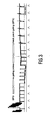
Figure 3 is a graph showing the waveform of a CVBS signal with no gating pulses during the serration pulse region under the influence of airplane flutter (prior art); -
Figure 4 is a graph showing the waveform of a CVBS signal with front porchgating pulses during the serration pulse region under the occurrence of airplane flutter; -
Figure 5 is a graph showing the waveform of the CVBS signal ofFigure 4 with additional details of timing instants for sync and gating pulses according to a first alternative of a method for changing the gating from back porch to front porch; and -
Figure 6 is a graph showing the wave form of the CVBS signal ofFigure 4 , but with additional details of timing instants for sync and gating pulses according to a second alternative of a method for changing the gating from back porch to front porch. - A schematic block diagram of a preferred embodiment of a gated digital AGC (automatic gain control) circuit for analog television receivers is shown in
Figure 1 . The shown circuit comprises aninput terminal 2 for inputting an IF (intermediate frequency) signal. Theinput terminal 2 is connected to an input of a controllableanalog AGC amplifier 4 whose output is coupled to anoutput terminal 6 for outputting the gained IF signal. The output of theanalog AGC amplifier 4 is further connected to an input of an analog/digital-converter 8 whose output is coupled to an input of a digitalsignal processing device 10. An output of the digitalsignal processing device 10 is connected to an input of a bit stream digital/analog-converter 12 whose output is coupled via afeed back loop 14 to an input of an analog non-critical first-order post filter 16. The output signal of thepost filter 16 is a control signal for controlling theAGC amplifier 4. - In the digital
signal processing device 10, a CVBS (color video blanking sync) signal is generated by demodulation of the inputted IF signal which has been digitized by the analog-digital-converter 8. Further, in the digitalsignal processing device 10, the horizontal line frequency is derived from the CVBS signal and is used to determine the level at the back porch region of the CVBS signal. This level is compared to a reference level for black. For this purpose, a H-PLL circuit is provided in the digitalsignal processing device 10. The difference between the level at the back porch region of the CVBS signal and the reference level for black is the resulting loop gain error which is integrated in the digitalsignal processing device 10. So, gating pulses are produced by being supplied from a H-PLL and V-INTEGRATOR. However, this is mainly for terrestrial noisy conditions. For good terrestrial picture conditions and in VCR (video cassette recorder)/STB (set top box) mode via an RF modulator, some gating pulses are derived from a conventional sync slicer which is also included in the digitalsignal processing device 10. When a copy protection (e.g. MACROVISION) from VCR or STB is set, some gating pulses are blanked. For this purpose, a corresponding flag is set in the digitalsignal processing device 10. - A multi-bit AGC error signal is outputted from the digital
signal processing device 10, converted into an analog signal by the digital/analog-converter 12 and applied as an AGC error signal to theAGC amplifier 4 via the feed backloop 14 and thepost filter 16 in order to keep the output signal of theAGC amplifier 4 constant. - The occurrence of the gating pulses is synchronized with the back porch region of the horizontal sync pulses. However, a critical time period is the serration pulse region forming part of the vertical sync period wherein serration pulses occur which have no back porch region. In
Figure 2 , it is shown the waveform of the CVBS signal without influence of airplane flutter and in particular the waveform of the CVBS signal during the beginning of the vertical sync period including the serration pulse region. - State of the art is either keeping the horizontal gating procedure or freezing it during the serration pulse region. Also known is the disabling of the gating during the serration pulse region. The result is a wrong AGC action in an annoying way in case a fast AGC response is required. Namely, a high speed response is necessary to control the outputted CVBS signal during airplane flutter (changing multi-path reception) and keep it on a constant level anytime. However, when the gating is interrupted during the serration pulse region, which lasts 2.5 to 3 line periods for all television standards, the AGC cannot react to airplane flutter during that critical time. As a consequence, the level of the outputted CVBS signal will vary accordingly, resulting in a changing picture contrast or even loss of synchronization. This situation is depicted in
Figure 3 showing the waveform of the CVBS signal under the influence of airplane flutter (80% AM, 80 Hz) and further showing the gating pulses indicated as upright arrows below the CVBS waveform. - To overcome this unwanted effect, the digital
signal processing device 10 changes the gating from back porch to front porch during the serration pulse region. So, the serration pulse region is gated with three time-shifted horizontal sync pulses by taking the error signal from the front porch measurement. In the digital domain this can be done with high accuracy. So, the AGC loop stays closed all the time and can thus function with good performance. This situation is depicted inFigure 4 showing the waveform of the CVBS signal under the occurrence of airplane flutter (80% AM, 80 Hz) and further showing the gaiting pulses indicated as upright arrows below the CVBS waveform, wherein front porch gating is carried out during the serration pulse region. -
Figure 5 shows more details of the timing instants for the sync and gating pulses with reference toFigure 4 . In particular,Figure 5 shows in more detail that during back porch gating the gating pulses occur a time distance ΔT1 after the occurrence of the sync pulses, whereas during the serration pulse region when front porch gating is carried out the gating pulses occur a time distance ΔT2 before the occurrence of the sync pulses. So, according toFigure 5 the gating pulses occur earlier by a time interval corresponding to the total time distance ΔT1 + ΔT2 to hit the front porch regions during the serration pulse region. -
Figure 6 shows an alternative method of changing from back porch gating to front porch gating wherein the gating pulses are delayed by a time interval ΔT3 behind the occurrence of the sync pulses to hit the next front porch region and the subsequent front porch regions during the serration pulse region. So, in the situation ofFigure 6 , the gating pulses occur later by a time interval corresponding to the time distance ΔT3 - ΔT1 between the first back porch region and the next front porch region within the serration pulse region so as to change from back porch gating to front porch gating. With respect thereto, it should be added that apart from the different kind of changing from back porch gating to front porch gating, the situation ofFigure 6 is the same as that ofFigures 4 and5 . - After all,
Figures 4 to 6 clearly show that the airplane flutter does not have any negative influence on the waveform of the CVBS signal. - As it becomes clear from the above description, the digital signal processing device 10 (
Figure 1 ) includes inter alia the function of an AGC detector. - Finally, three general cases be distinguished:
- 1) Noisy terrestrial reception mode:
- The gating pulses are derived from a H-PLL and V-INTEGRATOR which are included in the digital signal processing device 10 (
Figure 1 ). Moreover, the AGC loop bandwidth is made small (reduced AGC speed) to cope with noise spikes. The airplane flutter is masked by noise in that case.
- The gating pulses are derived from a H-PLL and V-INTEGRATOR which are included in the digital signal processing device 10 (
- 2) Good terrestrial reception and VCR/STB mode:
- A threshold detector senses the AGC voltage in the digital domain to monitor the IF (intermediate frequency) level. A flag is set, when the IF level is so high as to expect a good, nearly noise-free picture quality. During most of the active lines, carrying video information, the H-PLL supplies the gating pulses. However due to the VCR head switching, even the fast H-PLL looses tracking for some lines because of timing jitter. Therefore, an ordinary sync slicer must be employed in the digital signal processing device 10 (
Figure 1 ). The VCR head switching happens before the vertical sync period. So, the sync slicer provides gating pulses for 20 line periods (as an example) plus the vertical sync period which results in 39 to 45 line periods in total.
- A threshold detector senses the AGC voltage in the digital domain to monitor the IF (intermediate frequency) level. A flag is set, when the IF level is so high as to expect a good, nearly noise-free picture quality. During most of the active lines, carrying video information, the H-PLL supplies the gating pulses. However due to the VCR head switching, even the fast H-PLL looses tracking for some lines because of timing jitter. Therefore, an ordinary sync slicer must be employed in the digital signal processing device 10 (
- 3) Mode like in 2), but with MACROVISION copy protection:
- This situation is detected in a special circuit that finds out whether any copy protection pulses occur. In that case, the H-PLL gating pulses are interrupted during the vertical sync period (this is the period during which MACROVISION copy protection signals can occur). This can be done, because no airplane flutter is expected in case of a MACROVISION protected signal.
- Although, the invention is described above with reference to an example shown in the attached drawings, it is apparent that the invention is not restricted to it, but can vary in many ways within the scope disclosed in the attached claims.
Claims (10)
- An AGC, automatic gain control, detector device for television receivers displaying video pictures consisting of a plurality of horizontal lines to be built up successively using gating pulses for AGC, comprising- means (2) for inputting a CVBS, color video blanking sync, signal which includes horizontal sync pulses having a front porch region and a back porch region and occurring once a horizontal line during a horizontal sync period when generating a current video picture, and further includes vertical sync pulses occurring during a vertical sync period before the generation of a new video picture and including serration pulses which occur during a serration pulse region being part of the vertical sync period,- means (10) for generating gating pulses having a period which is equal to the line period of the horizontal sync pulses, and- means (10) for adjusting said gating pulses such that they occur at the back porch region (ΔT1) relative to the horizontal sync pulses,
characterized by- means (10) for shifting the occurrence of said gating pulses during the serration pulse region of the vertical sync period so that the gating pulses occur earlier by a time interval corresponding to the time distance (ΔT1 + ΔT2) between a front porch region and the next back porch region or later by a time interval corresponding to the time distance (ΔT3 - ΔT1) between a back porch region and the next front porch region. - The device according to claim 1,further characterized by- first means (10) for detecting the occurrence of the back porch region of the horizontal sync pulses, and- second means (10) for detecting the occurrence of the front porch region of the horizontal sync pulses,- wherein said first and second detecting means (10) are coupled to said shifting means (10), and at least said first detecting means (10) is coupled to said adjusting means (10).
- The device according to claim 1 or 2, characterized in that the device (10) is a digital AGC detector device.
- The device according to at least any one of claims 1 to 3, characterized in that the device (10) is provided for analog television receivers.
- The device according to at least any one of claims 1 to 4, wherein said gating pulses generating means (10) comprises a PLL circuit.
- The device according to claim 5, wherein said PLL circuit is a H-PLL circuit, and said gating pulses generating means (10) further comprises a V-INTEGRATOR.
- The device according to at least any one of claims 1 to 6, wherein said gating pulses generating means (10) comprises a sync slicer.
- A method for AGC (automatic gain control) detecting for television receivers displaying video pictures consisting of a plurality of horizontal lines to be built up successively using gating pulses for AGC, comprising the steps of- inputting a CVBS (color video blank sync) signal which includes horizontal sync pulses having a front porch region and a back porch region and occurring once a horizontal line during a horizontal sync period when generating a current video picture, and further includes vertical sync pulses occurring during a vertical sync period before the generation of a new video picture and including serration pulses which occur during a serration pulse region being part of the vertical sync period,- generating gating pulses having a period which is equal to the line period of the horizontal sync pulses, and- adjusting said gating pulses such that they occur at the back porch region (ΔT1) relative to the horizontal sync pulses,
characterized by the further step of- shifting the occurrence of said gating pulses during the serration pulse region of the vertical sync period so that the gating pulses occur earlier by a time interval corresponding to the time distance (ΔT1 + ΔT2) between a front porch region and the next back porch region or later by a time interval corresponding to the time distance (ΔT3 - ΔT1) between a back porch region and the next front porch region. - The method according to claim 8, characterized in that at least the step of shifting the occurrence of said gating pulses during the serration pulse region is carried out in the digital domain.
- The method according to claim 8 or 9, characterized in that the method is provided for analog television reception.
Priority Applications (1)
| Application Number | Priority Date | Filing Date | Title |
|---|---|---|---|
| EP03702843A EP1479228B1 (en) | 2002-02-09 | 2003-02-03 | Agc detector and method for agc detecting |
Applications Claiming Priority (4)
| Application Number | Priority Date | Filing Date | Title |
|---|---|---|---|
| EP02002917 | 2002-02-09 | ||
| EP02002917 | 2002-02-09 | ||
| EP03702843A EP1479228B1 (en) | 2002-02-09 | 2003-02-03 | Agc detector and method for agc detecting |
| PCT/IB2003/000399 WO2003067877A1 (en) | 2002-02-09 | 2003-02-03 | Agc detector and method for agc detecting |
Publications (2)
| Publication Number | Publication Date |
|---|---|
| EP1479228A1 EP1479228A1 (en) | 2004-11-24 |
| EP1479228B1 true EP1479228B1 (en) | 2009-09-23 |
Family
ID=27675612
Family Applications (1)
| Application Number | Title | Priority Date | Filing Date |
|---|---|---|---|
| EP03702843A Expired - Lifetime EP1479228B1 (en) | 2002-02-09 | 2003-02-03 | Agc detector and method for agc detecting |
Country Status (8)
| Country | Link |
|---|---|
| US (1) | US7259799B2 (en) |
| EP (1) | EP1479228B1 (en) |
| JP (1) | JP2005517360A (en) |
| CN (1) | CN1274142C (en) |
| AT (1) | ATE443968T1 (en) |
| AU (1) | AU2003205960A1 (en) |
| DE (1) | DE60329372D1 (en) |
| WO (1) | WO2003067877A1 (en) |
Families Citing this family (15)
| Publication number | Priority date | Publication date | Assignee | Title |
|---|---|---|---|---|
| US8175562B2 (en) * | 2006-10-27 | 2012-05-08 | Agere Systems Inc. | Automatic gain control for enhanced bit error rate performance |
| TWI354981B (en) * | 2007-01-29 | 2011-12-21 | Qisda Corp | Method and related device of increasing efficiency |
| US8385867B2 (en) | 2009-06-29 | 2013-02-26 | Silicon Laboratories Inc. | Tracking filter for a television tuner |
| US8576343B2 (en) | 2009-06-29 | 2013-11-05 | Silicon Laboratories Inc. | Digital signal processor (DSP) architecture for a hybrid television tuner |
| US8228431B2 (en) | 2009-08-31 | 2012-07-24 | Silicon Laboratories Inc. | Digital phase lock loop configurable as a frequency estimator |
| US8433970B2 (en) | 2010-03-31 | 2013-04-30 | Silicon Laboratories Inc. | Techniques to control power consumption in an iterative decoder by control of node configurations |
| US8555131B2 (en) | 2010-03-31 | 2013-10-08 | Silicon Laboratories Inc. | Techniques to control power consumption in an iterative decoder by control of node configurations |
| US8237869B2 (en) | 2010-03-31 | 2012-08-07 | Silicon Laboratories Inc. | Multi-standard digital demodulator for TV signals broadcast over cable, satellite and terrestrial networks |
| US8341486B2 (en) | 2010-03-31 | 2012-12-25 | Silicon Laboratories Inc. | Reducing power consumption in an iterative decoder |
| JP5251926B2 (en) * | 2010-06-16 | 2013-07-31 | セイコーエプソン株式会社 | Imaging apparatus and timing control circuit |
| US8346202B2 (en) | 2010-06-28 | 2013-01-01 | Silicon Laboratories Inc. | Digital intensive baseband chain of a receiver |
| US8837611B2 (en) | 2011-02-09 | 2014-09-16 | Silicon Laboratories Inc. | Memory-aided synchronization in a receiver |
| US8644370B2 (en) | 2012-01-25 | 2014-02-04 | Silicon Laboratories | Providing slope values for a demapper |
| US8451376B1 (en) * | 2012-04-24 | 2013-05-28 | Silicon Laboratories Inc. | Automatic gain control (AGC) for analog TV signals using feed-forward signal path delay |
| US8959274B2 (en) | 2012-09-06 | 2015-02-17 | Silicon Laboratories Inc. | Providing a serial download path to devices |
Family Cites Families (10)
| Publication number | Priority date | Publication date | Assignee | Title |
|---|---|---|---|---|
| US2796462A (en) * | 1952-03-19 | 1957-06-18 | Rca Corp | Automatic gain control circuits with hum compensation |
| US2938950A (en) * | 1954-01-08 | 1960-05-31 | Ferguson Radio Corp | Automatic gain control circuits for television signal amplifiers |
| US3531590A (en) * | 1966-12-05 | 1970-09-29 | Motorola Inc | Automatic gain control circuit |
| US3560648A (en) * | 1968-08-29 | 1971-02-02 | Bell Telephone Labor Inc | Sampled data automatic gain control circuit |
| NL169811C (en) * | 1975-10-03 | 1982-08-16 | Philips Nv | IMAGE CONTROL SYNCHRONIZATION CIRCUIT AND TV RECEIVER. |
| US4212032A (en) * | 1978-08-18 | 1980-07-08 | Rca Corporation | Synchronization and gain control circuit |
| US4216502A (en) * | 1978-08-18 | 1980-08-05 | Rca Corporation | Peak detector circuit |
| JPS5815377A (en) * | 1981-07-21 | 1983-01-28 | Clarion Co Ltd | Agc system for television signal receiver |
| JPS622783A (en) * | 1985-06-28 | 1987-01-08 | Toshiba Corp | Agc wave detecting circuit |
| US6188832B1 (en) * | 1997-05-07 | 2001-02-13 | Microvision Corp | Method and apparatus for modifications made to a video signal to inhibit the making of acceptable videotape recordings |
-
2003
- 2003-02-03 JP JP2003567088A patent/JP2005517360A/en not_active Ceased
- 2003-02-03 DE DE60329372T patent/DE60329372D1/en not_active Expired - Lifetime
- 2003-02-03 CN CN03803520.0A patent/CN1274142C/en not_active Expired - Fee Related
- 2003-02-03 US US10/503,686 patent/US7259799B2/en not_active Expired - Fee Related
- 2003-02-03 AU AU2003205960A patent/AU2003205960A1/en not_active Abandoned
- 2003-02-03 EP EP03702843A patent/EP1479228B1/en not_active Expired - Lifetime
- 2003-02-03 AT AT03702843T patent/ATE443968T1/en not_active IP Right Cessation
- 2003-02-03 WO PCT/IB2003/000399 patent/WO2003067877A1/en active Application Filing
Also Published As
| Publication number | Publication date |
|---|---|
| CN1274142C (en) | 2006-09-06 |
| WO2003067877A1 (en) | 2003-08-14 |
| US20050088367A1 (en) | 2005-04-28 |
| AU2003205960A1 (en) | 2003-09-02 |
| ATE443968T1 (en) | 2009-10-15 |
| DE60329372D1 (en) | 2009-11-05 |
| US7259799B2 (en) | 2007-08-21 |
| CN1631036A (en) | 2005-06-22 |
| EP1479228A1 (en) | 2004-11-24 |
| JP2005517360A (en) | 2005-06-09 |
Similar Documents
| Publication | Publication Date | Title |
|---|---|---|
| EP1479228B1 (en) | Agc detector and method for agc detecting | |
| US4819098A (en) | Method and apparatus for clustering modifications made to a video signal to inhibit the making of acceptable videotape recordings | |
| US5251041A (en) | Method and apparatus for modifying a video signal to inhibit unauthorized videotape recording and subsequent reproduction thereof | |
| US20110002663A1 (en) | Method and apparatus for attenuating or eliminating at least a portion of color burst modifications to a video signal | |
| US20070242930A1 (en) | Method and apparatus for modifying a video signal or for providing a copy protection signal by adding selected negative going and positive going pulses | |
| US4963969A (en) | Automatic gain control device | |
| JP3662544B2 (en) | Television system | |
| US6188832B1 (en) | Method and apparatus for modifications made to a video signal to inhibit the making of acceptable videotape recordings | |
| EP0899945B1 (en) | Method for obtaining line synchronization information items from a video signal, and apparatus for carrying out the method | |
| US7173668B2 (en) | Equilibrium based horizontal sync detector for video decoder | |
| KR100316675B1 (en) | Clock Signal Generator | |
| JPS5945276B2 (en) | Dropout compensation circuit | |
| GB2396767A (en) | Inserting positive-going pulses to back porch of a video signal for copy protection | |
| EP0479610B1 (en) | Television receiver | |
| US5309226A (en) | Means for cancelling ghost signals in response to the reception of a non-standard television video signal | |
| KR100447004B1 (en) | Method and apparatus for modification made to a video signal to inhibit the making of acceptable vidoetape recordings | |
| US5103477A (en) | Method and apparatus for descrambling a television signal | |
| KR20100045518A (en) | Method and apparatus for synthesizing a copy protection or content signal with improved playability of a tv set | |
| JPS6161310B2 (en) | ||
| JP2993676B2 (en) | Television receiver | |
| JPH0766990A (en) | Analog signal processing circuit | |
| JPH05336458A (en) | Television receiver and television receiving tuner | |
| KR890004227B1 (en) | Devices for processing colour signals | |
| KR19990021154A (en) | VTR regeneration method capable of controlling channel boundary correction and suitable circuit for performing this | |
| JPH0546186U (en) | Teletext playback device |
Legal Events
| Date | Code | Title | Description |
|---|---|---|---|
| PUAI | Public reference made under article 153(3) epc to a published international application that has entered the european phase |
Free format text: ORIGINAL CODE: 0009012 |
|
| 17P | Request for examination filed |
Effective date: 20040909 |
|
| AK | Designated contracting states |
Kind code of ref document: A1 Designated state(s): AT BE BG CH CY CZ DE DK EE ES FI FR GB GR HU IE IT LI LU MC NL PT SE SI SK TR |
|
| AX | Request for extension of the european patent |
Extension state: AL LT LV MK RO |
|
| RAP1 | Party data changed (applicant data changed or rights of an application transferred) |
Owner name: PHILIPS INTELLECTUAL PROPERTY & STANDARDS GMBH Owner name: KONINKLIJKE PHILIPS ELECTRONICS N.V. |
|
| RAP1 | Party data changed (applicant data changed or rights of an application transferred) |
Owner name: NXP B.V. |
|
| GRAP | Despatch of communication of intention to grant a patent |
Free format text: ORIGINAL CODE: EPIDOSNIGR1 |
|
| GRAS | Grant fee paid |
Free format text: ORIGINAL CODE: EPIDOSNIGR3 |
|
| GRAA | (expected) grant |
Free format text: ORIGINAL CODE: 0009210 |
|
| AK | Designated contracting states |
Kind code of ref document: B1 Designated state(s): AT BE BG CH CY CZ DE DK EE ES FI FR GB GR HU IE IT LI LU MC NL PT SE SI SK TR |
|
| REG | Reference to a national code |
Ref country code: GB Ref legal event code: FG4D |
|
| REG | Reference to a national code |
Ref country code: CH Ref legal event code: EP |
|
| REG | Reference to a national code |
Ref country code: IE Ref legal event code: FG4D |
|
| REF | Corresponds to: |
Ref document number: 60329372 Country of ref document: DE Date of ref document: 20091105 Kind code of ref document: P |
|
| PG25 | Lapsed in a contracting state [announced via postgrant information from national office to epo] |
Ref country code: SE Free format text: LAPSE BECAUSE OF FAILURE TO SUBMIT A TRANSLATION OF THE DESCRIPTION OR TO PAY THE FEE WITHIN THE PRESCRIBED TIME-LIMIT Effective date: 20090923 Ref country code: FI Free format text: LAPSE BECAUSE OF FAILURE TO SUBMIT A TRANSLATION OF THE DESCRIPTION OR TO PAY THE FEE WITHIN THE PRESCRIBED TIME-LIMIT Effective date: 20090923 |
|
| PG25 | Lapsed in a contracting state [announced via postgrant information from national office to epo] |
Ref country code: SI Free format text: LAPSE BECAUSE OF FAILURE TO SUBMIT A TRANSLATION OF THE DESCRIPTION OR TO PAY THE FEE WITHIN THE PRESCRIBED TIME-LIMIT Effective date: 20090923 |
|
| NLV1 | Nl: lapsed or annulled due to failure to fulfill the requirements of art. 29p and 29m of the patents act | ||
| PG25 | Lapsed in a contracting state [announced via postgrant information from national office to epo] |
Ref country code: CY Free format text: LAPSE BECAUSE OF FAILURE TO SUBMIT A TRANSLATION OF THE DESCRIPTION OR TO PAY THE FEE WITHIN THE PRESCRIBED TIME-LIMIT Effective date: 20090923 |
|
| PG25 | Lapsed in a contracting state [announced via postgrant information from national office to epo] |
Ref country code: ES Free format text: LAPSE BECAUSE OF FAILURE TO SUBMIT A TRANSLATION OF THE DESCRIPTION OR TO PAY THE FEE WITHIN THE PRESCRIBED TIME-LIMIT Effective date: 20100103 Ref country code: PT Free format text: LAPSE BECAUSE OF FAILURE TO SUBMIT A TRANSLATION OF THE DESCRIPTION OR TO PAY THE FEE WITHIN THE PRESCRIBED TIME-LIMIT Effective date: 20100125 Ref country code: EE Free format text: LAPSE BECAUSE OF FAILURE TO SUBMIT A TRANSLATION OF THE DESCRIPTION OR TO PAY THE FEE WITHIN THE PRESCRIBED TIME-LIMIT Effective date: 20090923 Ref country code: CZ Free format text: LAPSE BECAUSE OF FAILURE TO SUBMIT A TRANSLATION OF THE DESCRIPTION OR TO PAY THE FEE WITHIN THE PRESCRIBED TIME-LIMIT Effective date: 20090923 |
|
| PG25 | Lapsed in a contracting state [announced via postgrant information from national office to epo] |
Ref country code: SK Free format text: LAPSE BECAUSE OF FAILURE TO SUBMIT A TRANSLATION OF THE DESCRIPTION OR TO PAY THE FEE WITHIN THE PRESCRIBED TIME-LIMIT Effective date: 20090923 |
|
| PG25 | Lapsed in a contracting state [announced via postgrant information from national office to epo] |
Ref country code: AT Free format text: LAPSE BECAUSE OF FAILURE TO SUBMIT A TRANSLATION OF THE DESCRIPTION OR TO PAY THE FEE WITHIN THE PRESCRIBED TIME-LIMIT Effective date: 20090923 Ref country code: BE Free format text: LAPSE BECAUSE OF FAILURE TO SUBMIT A TRANSLATION OF THE DESCRIPTION OR TO PAY THE FEE WITHIN THE PRESCRIBED TIME-LIMIT Effective date: 20090923 |
|
| PG25 | Lapsed in a contracting state [announced via postgrant information from national office to epo] |
Ref country code: DK Free format text: LAPSE BECAUSE OF FAILURE TO SUBMIT A TRANSLATION OF THE DESCRIPTION OR TO PAY THE FEE WITHIN THE PRESCRIBED TIME-LIMIT Effective date: 20090923 Ref country code: NL Free format text: LAPSE BECAUSE OF FAILURE TO SUBMIT A TRANSLATION OF THE DESCRIPTION OR TO PAY THE FEE WITHIN THE PRESCRIBED TIME-LIMIT Effective date: 20090923 |
|
| PLBE | No opposition filed within time limit |
Free format text: ORIGINAL CODE: 0009261 |
|
| STAA | Information on the status of an ep patent application or granted ep patent |
Free format text: STATUS: NO OPPOSITION FILED WITHIN TIME LIMIT |
|
| 26N | No opposition filed |
Effective date: 20100624 |
|
| REG | Reference to a national code |
Ref country code: CH Ref legal event code: PL |
|
| PG25 | Lapsed in a contracting state [announced via postgrant information from national office to epo] |
Ref country code: MC Free format text: LAPSE BECAUSE OF NON-PAYMENT OF DUE FEES Effective date: 20100301 Ref country code: LI Free format text: LAPSE BECAUSE OF NON-PAYMENT OF DUE FEES Effective date: 20100228 Ref country code: CH Free format text: LAPSE BECAUSE OF NON-PAYMENT OF DUE FEES Effective date: 20100228 Ref country code: GR Free format text: LAPSE BECAUSE OF FAILURE TO SUBMIT A TRANSLATION OF THE DESCRIPTION OR TO PAY THE FEE WITHIN THE PRESCRIBED TIME-LIMIT Effective date: 20091224 |
|
| PG25 | Lapsed in a contracting state [announced via postgrant information from national office to epo] |
Ref country code: IE Free format text: LAPSE BECAUSE OF NON-PAYMENT OF DUE FEES Effective date: 20100203 |
|
| PG25 | Lapsed in a contracting state [announced via postgrant information from national office to epo] |
Ref country code: IT Free format text: LAPSE BECAUSE OF FAILURE TO SUBMIT A TRANSLATION OF THE DESCRIPTION OR TO PAY THE FEE WITHIN THE PRESCRIBED TIME-LIMIT Effective date: 20090923 |
|
| PG25 | Lapsed in a contracting state [announced via postgrant information from national office to epo] |
Ref country code: LU Free format text: LAPSE BECAUSE OF NON-PAYMENT OF DUE FEES Effective date: 20100203 Ref country code: HU Free format text: LAPSE BECAUSE OF FAILURE TO SUBMIT A TRANSLATION OF THE DESCRIPTION OR TO PAY THE FEE WITHIN THE PRESCRIBED TIME-LIMIT Effective date: 20100324 Ref country code: BG Free format text: LAPSE BECAUSE OF FAILURE TO SUBMIT A TRANSLATION OF THE DESCRIPTION OR TO PAY THE FEE WITHIN THE PRESCRIBED TIME-LIMIT Effective date: 20090923 |
|
| PG25 | Lapsed in a contracting state [announced via postgrant information from national office to epo] |
Ref country code: TR Free format text: LAPSE BECAUSE OF FAILURE TO SUBMIT A TRANSLATION OF THE DESCRIPTION OR TO PAY THE FEE WITHIN THE PRESCRIBED TIME-LIMIT Effective date: 20090923 |
|
| REG | Reference to a national code |
Ref country code: GB Ref legal event code: 732E Free format text: REGISTERED BETWEEN 20130606 AND 20130612 |
|
| REG | Reference to a national code |
Ref country code: FR Ref legal event code: PLFP Year of fee payment: 13 |
|
| REG | Reference to a national code |
Ref country code: FR Ref legal event code: PLFP Year of fee payment: 14 |
|
| REG | Reference to a national code |
Ref country code: FR Ref legal event code: PLFP Year of fee payment: 15 |
|
| REG | Reference to a national code |
Ref country code: FR Ref legal event code: PLFP Year of fee payment: 16 |
|
| PGFP | Annual fee paid to national office [announced via postgrant information from national office to epo] |
Ref country code: GB Payment date: 20200123 Year of fee payment: 18 Ref country code: DE Payment date: 20200121 Year of fee payment: 18 |
|
| PGFP | Annual fee paid to national office [announced via postgrant information from national office to epo] |
Ref country code: FR Payment date: 20200122 Year of fee payment: 18 |
|
| REG | Reference to a national code |
Ref country code: DE Ref legal event code: R119 Ref document number: 60329372 Country of ref document: DE |
|
| GBPC | Gb: european patent ceased through non-payment of renewal fee |
Effective date: 20210203 |
|
| PG25 | Lapsed in a contracting state [announced via postgrant information from national office to epo] |
Ref country code: DE Free format text: LAPSE BECAUSE OF NON-PAYMENT OF DUE FEES Effective date: 20210901 Ref country code: FR Free format text: LAPSE BECAUSE OF NON-PAYMENT OF DUE FEES Effective date: 20210228 Ref country code: GB Free format text: LAPSE BECAUSE OF NON-PAYMENT OF DUE FEES Effective date: 20210203 |