EP1479119B1 - Positive electrode films for alkali metal polymer batteries and method for making same - Google Patents
Positive electrode films for alkali metal polymer batteries and method for making same Download PDFInfo
- Publication number
- EP1479119B1 EP1479119B1 EP03704148A EP03704148A EP1479119B1 EP 1479119 B1 EP1479119 B1 EP 1479119B1 EP 03704148 A EP03704148 A EP 03704148A EP 03704148 A EP03704148 A EP 03704148A EP 1479119 B1 EP1479119 B1 EP 1479119B1
- Authority
- EP
- European Patent Office
- Prior art keywords
- positive electrode
- sheet
- micrometers
- thickness
- substrate
- Prior art date
- Legal status (The legal status is an assumption and is not a legal conclusion. Google has not performed a legal analysis and makes no representation as to the accuracy of the status listed.)
- Expired - Lifetime
Links
- 238000000034 method Methods 0.000 title claims abstract description 48
- 229920000642 polymer Polymers 0.000 title claims abstract description 25
- 229910052783 alkali metal Inorganic materials 0.000 title description 9
- 150000001340 alkali metals Chemical class 0.000 title description 9
- 230000008569 process Effects 0.000 claims abstract description 42
- 239000007787 solid Substances 0.000 claims abstract description 34
- 239000000203 mixture Substances 0.000 claims abstract description 33
- 238000002156 mixing Methods 0.000 claims abstract description 32
- 239000000758 substrate Substances 0.000 claims abstract description 28
- 239000000463 material Substances 0.000 claims abstract description 22
- 229910003002 lithium salt Inorganic materials 0.000 claims abstract description 11
- 159000000002 lithium salts Chemical class 0.000 claims abstract description 11
- 230000002687 intercalation Effects 0.000 claims abstract description 9
- 238000009830 intercalation Methods 0.000 claims abstract description 9
- 239000004020 conductor Substances 0.000 claims abstract description 7
- 229910052744 lithium Inorganic materials 0.000 claims abstract description 7
- 229920000570 polyether Polymers 0.000 claims abstract description 6
- 239000004721 Polyphenylene oxide Substances 0.000 claims abstract description 5
- WHXSMMKQMYFTQS-UHFFFAOYSA-N Lithium Chemical compound [Li] WHXSMMKQMYFTQS-UHFFFAOYSA-N 0.000 claims abstract description 4
- OKTJSMMVPCPJKN-UHFFFAOYSA-N Carbon Chemical compound [C] OKTJSMMVPCPJKN-UHFFFAOYSA-N 0.000 claims description 31
- 239000007774 positive electrode material Substances 0.000 claims description 24
- 229920003171 Poly (ethylene oxide) Polymers 0.000 claims description 19
- 229910052799 carbon Inorganic materials 0.000 claims description 18
- 239000002245 particle Substances 0.000 claims description 16
- 229910002804 graphite Inorganic materials 0.000 claims description 14
- 239000010439 graphite Substances 0.000 claims description 14
- VYPSYNLAJGMNEJ-UHFFFAOYSA-N Silicium dioxide Chemical compound O=[Si]=O VYPSYNLAJGMNEJ-UHFFFAOYSA-N 0.000 claims description 11
- 239000005518 polymer electrolyte Substances 0.000 claims description 11
- XHCLAFWTIXFWPH-UHFFFAOYSA-N [O-2].[O-2].[O-2].[O-2].[O-2].[V+5].[V+5] Chemical compound [O-2].[O-2].[O-2].[O-2].[O-2].[V+5].[V+5] XHCLAFWTIXFWPH-UHFFFAOYSA-N 0.000 claims description 9
- 229920002981 polyvinylidene fluoride Polymers 0.000 claims description 9
- 229910001935 vanadium oxide Inorganic materials 0.000 claims description 9
- 229910052782 aluminium Inorganic materials 0.000 claims description 8
- XAGFODPZIPBFFR-UHFFFAOYSA-N aluminium Chemical group [Al] XAGFODPZIPBFFR-UHFFFAOYSA-N 0.000 claims description 8
- -1 polypropylene Polymers 0.000 claims description 8
- 238000000151 deposition Methods 0.000 claims description 6
- 239000000314 lubricant Substances 0.000 claims description 6
- 239000004014 plasticizer Substances 0.000 claims description 6
- 239000000843 powder Substances 0.000 claims description 6
- 239000002033 PVDF binder Substances 0.000 claims description 5
- 239000000654 additive Substances 0.000 claims description 5
- 230000000996 additive effect Effects 0.000 claims description 5
- 229910044991 metal oxide Inorganic materials 0.000 claims description 5
- 150000004706 metal oxides Chemical class 0.000 claims description 5
- 229920002620 polyvinyl fluoride Polymers 0.000 claims description 5
- 238000005096 rolling process Methods 0.000 claims description 5
- XLYOFNOQVPJJNP-UHFFFAOYSA-N water Substances O XLYOFNOQVPJJNP-UHFFFAOYSA-N 0.000 claims description 5
- 239000004743 Polypropylene Substances 0.000 claims description 4
- 229910052751 metal Inorganic materials 0.000 claims description 4
- 239000002184 metal Substances 0.000 claims description 4
- 229920001155 polypropylene Polymers 0.000 claims description 4
- 239000000377 silicon dioxide Substances 0.000 claims description 4
- XTHFKEDIFFGKHM-UHFFFAOYSA-N Dimethoxyethane Chemical compound COCCOC XTHFKEDIFFGKHM-UHFFFAOYSA-N 0.000 claims description 3
- 239000004698 Polyethylene Substances 0.000 claims description 3
- 239000002202 Polyethylene glycol Substances 0.000 claims description 3
- GWEVSGVZZGPLCZ-UHFFFAOYSA-N Titan oxide Chemical compound O=[Ti]=O GWEVSGVZZGPLCZ-UHFFFAOYSA-N 0.000 claims description 3
- 229920000573 polyethylene Polymers 0.000 claims description 3
- 229920001223 polyethylene glycol Polymers 0.000 claims description 3
- OGIDPMRJRNCKJF-UHFFFAOYSA-N titanium oxide Inorganic materials [Ti]=O OGIDPMRJRNCKJF-UHFFFAOYSA-N 0.000 claims description 3
- 238000012546 transfer Methods 0.000 claims description 3
- KMTRUDSVKNLOMY-UHFFFAOYSA-N Ethylene carbonate Chemical compound O=C1OCCO1 KMTRUDSVKNLOMY-UHFFFAOYSA-N 0.000 claims description 2
- 229910000733 Li alloy Inorganic materials 0.000 claims description 2
- 229910012954 LiV308 Inorganic materials 0.000 claims description 2
- 239000006182 cathode active material Substances 0.000 claims description 2
- 229920001577 copolymer Polymers 0.000 claims description 2
- MTHSVFCYNBDYFN-UHFFFAOYSA-N diethylene glycol Chemical compound OCCOCCO MTHSVFCYNBDYFN-UHFFFAOYSA-N 0.000 claims description 2
- 239000002001 electrolyte material Substances 0.000 claims description 2
- 239000001989 lithium alloy Substances 0.000 claims description 2
- 229920005596 polymer binder Polymers 0.000 claims description 2
- 239000002491 polymer binding agent Substances 0.000 claims description 2
- RUOJZAUFBMNUDX-UHFFFAOYSA-N propylene carbonate Chemical compound CC1COC(=O)O1 RUOJZAUFBMNUDX-UHFFFAOYSA-N 0.000 claims description 2
- 238000010030 laminating Methods 0.000 claims 2
- BYEAHWXPCBROCE-UHFFFAOYSA-N 1,1,1,3,3,3-hexafluoropropan-2-ol Chemical compound FC(F)(F)C(O)C(F)(F)F BYEAHWXPCBROCE-UHFFFAOYSA-N 0.000 claims 1
- 229920003002 synthetic resin Polymers 0.000 claims 1
- 239000000057 synthetic resin Substances 0.000 claims 1
- KEROTHRUZYBWCY-UHFFFAOYSA-N tridecyl 2-methylprop-2-enoate Chemical compound CCCCCCCCCCCCCOC(=O)C(C)=C KEROTHRUZYBWCY-UHFFFAOYSA-N 0.000 claims 1
- 238000001125 extrusion Methods 0.000 abstract description 28
- 239000010408 film Substances 0.000 description 61
- 239000010406 cathode material Substances 0.000 description 39
- 239000011230 binding agent Substances 0.000 description 8
- 239000002131 composite material Substances 0.000 description 8
- 239000010409 thin film Substances 0.000 description 7
- 239000011149 active material Substances 0.000 description 6
- 238000004519 manufacturing process Methods 0.000 description 6
- 239000002002 slurry Substances 0.000 description 5
- 239000002904 solvent Substances 0.000 description 5
- 239000006229 carbon black Substances 0.000 description 4
- 239000011231 conductive filler Substances 0.000 description 4
- 239000007788 liquid Substances 0.000 description 4
- 239000006257 cathode slurry Substances 0.000 description 3
- 230000003247 decreasing effect Effects 0.000 description 3
- 230000000694 effects Effects 0.000 description 3
- 239000003792 electrolyte Substances 0.000 description 3
- 229910021485 fumed silica Inorganic materials 0.000 description 3
- 238000012545 processing Methods 0.000 description 3
- RYGMFSIKBFXOCR-UHFFFAOYSA-N Copper Chemical compound [Cu] RYGMFSIKBFXOCR-UHFFFAOYSA-N 0.000 description 2
- 230000009471 action Effects 0.000 description 2
- 230000000181 anti-adherent effect Effects 0.000 description 2
- 229920001940 conductive polymer Polymers 0.000 description 2
- 239000011889 copper foil Substances 0.000 description 2
- 230000006837 decompression Effects 0.000 description 2
- 238000013461 design Methods 0.000 description 2
- 239000007772 electrode material Substances 0.000 description 2
- 239000011888 foil Substances 0.000 description 2
- 238000010309 melting process Methods 0.000 description 2
- 229920002239 polyacrylonitrile Polymers 0.000 description 2
- 229920000036 polyvinylpyrrolidone Polymers 0.000 description 2
- 239000001267 polyvinylpyrrolidone Substances 0.000 description 2
- 235000013855 polyvinylpyrrolidone Nutrition 0.000 description 2
- 238000003860 storage Methods 0.000 description 2
- 241000251468 Actinopterygii Species 0.000 description 1
- 229910000838 Al alloy Inorganic materials 0.000 description 1
- KRHYYFGTRYWZRS-UHFFFAOYSA-M Fluoride anion Chemical compound [F-] KRHYYFGTRYWZRS-UHFFFAOYSA-M 0.000 description 1
- ATJFFYVFTNAWJD-UHFFFAOYSA-N Tin Chemical compound [Sn] ATJFFYVFTNAWJD-UHFFFAOYSA-N 0.000 description 1
- JFBZPFYRPYOZCQ-UHFFFAOYSA-N [Li].[Al] Chemical compound [Li].[Al] JFBZPFYRPYOZCQ-UHFFFAOYSA-N 0.000 description 1
- 239000000853 adhesive Substances 0.000 description 1
- 230000001070 adhesive effect Effects 0.000 description 1
- 238000005054 agglomeration Methods 0.000 description 1
- 230000002776 aggregation Effects 0.000 description 1
- 229910045601 alloy Inorganic materials 0.000 description 1
- 239000000956 alloy Substances 0.000 description 1
- 239000003963 antioxidant agent Substances 0.000 description 1
- 230000003078 antioxidant effect Effects 0.000 description 1
- 230000015572 biosynthetic process Effects 0.000 description 1
- 238000003490 calendering Methods 0.000 description 1
- 230000015556 catabolic process Effects 0.000 description 1
- 239000011248 coating agent Substances 0.000 description 1
- 238000000576 coating method Methods 0.000 description 1
- 150000001875 compounds Chemical class 0.000 description 1
- 230000007423 decrease Effects 0.000 description 1
- 238000006731 degradation reaction Methods 0.000 description 1
- 230000000593 degrading effect Effects 0.000 description 1
- 230000001627 detrimental effect Effects 0.000 description 1
- 238000001704 evaporation Methods 0.000 description 1
- 239000012530 fluid Substances 0.000 description 1
- 238000010438 heat treatment Methods 0.000 description 1
- 238000002347 injection Methods 0.000 description 1
- 239000007924 injection Substances 0.000 description 1
- 239000011810 insulating material Substances 0.000 description 1
- 238000003475 lamination Methods 0.000 description 1
- 239000011244 liquid electrolyte Substances 0.000 description 1
- FUJCRWPEOMXPAD-UHFFFAOYSA-N lithium oxide Chemical compound [Li+].[Li+].[O-2] FUJCRWPEOMXPAD-UHFFFAOYSA-N 0.000 description 1
- 229910001947 lithium oxide Inorganic materials 0.000 description 1
- 238000002844 melting Methods 0.000 description 1
- 230000008018 melting Effects 0.000 description 1
- 150000002739 metals Chemical class 0.000 description 1
- 238000012986 modification Methods 0.000 description 1
- 230000004048 modification Effects 0.000 description 1
- 230000001737 promoting effect Effects 0.000 description 1
- 150000003839 salts Chemical class 0.000 description 1
- 239000000243 solution Substances 0.000 description 1
- ZUHZGEOKBKGPSW-UHFFFAOYSA-N tetraglyme Chemical compound COCCOCCOCCOCCOC ZUHZGEOKBKGPSW-UHFFFAOYSA-N 0.000 description 1
- 231100000331 toxic Toxicity 0.000 description 1
- 230000002588 toxic effect Effects 0.000 description 1
- YFNKIDBQEZZDLK-UHFFFAOYSA-N triglyme Chemical compound COCCOCCOCCOC YFNKIDBQEZZDLK-UHFFFAOYSA-N 0.000 description 1
Images



Classifications
-
- B—PERFORMING OPERATIONS; TRANSPORTING
- B32—LAYERED PRODUCTS
- B32B—LAYERED PRODUCTS, i.e. PRODUCTS BUILT-UP OF STRATA OF FLAT OR NON-FLAT, e.g. CELLULAR OR HONEYCOMB, FORM
- B32B37/00—Methods or apparatus for laminating, e.g. by curing or by ultrasonic bonding
- B32B37/14—Methods or apparatus for laminating, e.g. by curing or by ultrasonic bonding characterised by the properties of the layers
- B32B37/15—Methods or apparatus for laminating, e.g. by curing or by ultrasonic bonding characterised by the properties of the layers with at least one layer being manufactured and immediately laminated before reaching its stable state, e.g. in which a layer is extruded and laminated while in semi-molten state
- B32B37/153—Methods or apparatus for laminating, e.g. by curing or by ultrasonic bonding characterised by the properties of the layers with at least one layer being manufactured and immediately laminated before reaching its stable state, e.g. in which a layer is extruded and laminated while in semi-molten state at least one layer is extruded and immediately laminated while in semi-molten state
-
- B—PERFORMING OPERATIONS; TRANSPORTING
- B29—WORKING OF PLASTICS; WORKING OF SUBSTANCES IN A PLASTIC STATE IN GENERAL
- B29C—SHAPING OR JOINING OF PLASTICS; SHAPING OF MATERIAL IN A PLASTIC STATE, NOT OTHERWISE PROVIDED FOR; AFTER-TREATMENT OF THE SHAPED PRODUCTS, e.g. REPAIRING
- B29C48/00—Extrusion moulding, i.e. expressing the moulding material through a die or nozzle which imparts the desired form; Apparatus therefor
- B29C48/022—Extrusion moulding, i.e. expressing the moulding material through a die or nozzle which imparts the desired form; Apparatus therefor characterised by the choice of material
-
- B—PERFORMING OPERATIONS; TRANSPORTING
- B29—WORKING OF PLASTICS; WORKING OF SUBSTANCES IN A PLASTIC STATE IN GENERAL
- B29C—SHAPING OR JOINING OF PLASTICS; SHAPING OF MATERIAL IN A PLASTIC STATE, NOT OTHERWISE PROVIDED FOR; AFTER-TREATMENT OF THE SHAPED PRODUCTS, e.g. REPAIRING
- B29C48/00—Extrusion moulding, i.e. expressing the moulding material through a die or nozzle which imparts the desired form; Apparatus therefor
- B29C48/03—Extrusion moulding, i.e. expressing the moulding material through a die or nozzle which imparts the desired form; Apparatus therefor characterised by the shape of the extruded material at extrusion
- B29C48/07—Flat, e.g. panels
- B29C48/08—Flat, e.g. panels flexible, e.g. films
-
- B—PERFORMING OPERATIONS; TRANSPORTING
- B29—WORKING OF PLASTICS; WORKING OF SUBSTANCES IN A PLASTIC STATE IN GENERAL
- B29C—SHAPING OR JOINING OF PLASTICS; SHAPING OF MATERIAL IN A PLASTIC STATE, NOT OTHERWISE PROVIDED FOR; AFTER-TREATMENT OF THE SHAPED PRODUCTS, e.g. REPAIRING
- B29C48/00—Extrusion moulding, i.e. expressing the moulding material through a die or nozzle which imparts the desired form; Apparatus therefor
- B29C48/25—Component parts, details or accessories; Auxiliary operations
- B29C48/30—Extrusion nozzles or dies
- B29C48/305—Extrusion nozzles or dies having a wide opening, e.g. for forming sheets
-
- B—PERFORMING OPERATIONS; TRANSPORTING
- B29—WORKING OF PLASTICS; WORKING OF SUBSTANCES IN A PLASTIC STATE IN GENERAL
- B29C—SHAPING OR JOINING OF PLASTICS; SHAPING OF MATERIAL IN A PLASTIC STATE, NOT OTHERWISE PROVIDED FOR; AFTER-TREATMENT OF THE SHAPED PRODUCTS, e.g. REPAIRING
- B29C48/00—Extrusion moulding, i.e. expressing the moulding material through a die or nozzle which imparts the desired form; Apparatus therefor
- B29C48/25—Component parts, details or accessories; Auxiliary operations
- B29C48/36—Means for plasticising or homogenising the moulding material or forcing it through the nozzle or die
- B29C48/365—Means for plasticising or homogenising the moulding material or forcing it through the nozzle or die using pumps, e.g. piston pumps
- B29C48/37—Gear pumps
-
- B—PERFORMING OPERATIONS; TRANSPORTING
- B29—WORKING OF PLASTICS; WORKING OF SUBSTANCES IN A PLASTIC STATE IN GENERAL
- B29C—SHAPING OR JOINING OF PLASTICS; SHAPING OF MATERIAL IN A PLASTIC STATE, NOT OTHERWISE PROVIDED FOR; AFTER-TREATMENT OF THE SHAPED PRODUCTS, e.g. REPAIRING
- B29C48/00—Extrusion moulding, i.e. expressing the moulding material through a die or nozzle which imparts the desired form; Apparatus therefor
- B29C48/25—Component parts, details or accessories; Auxiliary operations
- B29C48/36—Means for plasticising or homogenising the moulding material or forcing it through the nozzle or die
- B29C48/395—Means for plasticising or homogenising the moulding material or forcing it through the nozzle or die using screws surrounded by a cooperating barrel, e.g. single screw extruders
- B29C48/40—Means for plasticising or homogenising the moulding material or forcing it through the nozzle or die using screws surrounded by a cooperating barrel, e.g. single screw extruders using two or more parallel screws or at least two parallel non-intermeshing screws, e.g. twin screw extruders
-
- B—PERFORMING OPERATIONS; TRANSPORTING
- B29—WORKING OF PLASTICS; WORKING OF SUBSTANCES IN A PLASTIC STATE IN GENERAL
- B29C—SHAPING OR JOINING OF PLASTICS; SHAPING OF MATERIAL IN A PLASTIC STATE, NOT OTHERWISE PROVIDED FOR; AFTER-TREATMENT OF THE SHAPED PRODUCTS, e.g. REPAIRING
- B29C48/00—Extrusion moulding, i.e. expressing the moulding material through a die or nozzle which imparts the desired form; Apparatus therefor
- B29C48/25—Component parts, details or accessories; Auxiliary operations
- B29C48/36—Means for plasticising or homogenising the moulding material or forcing it through the nozzle or die
- B29C48/395—Means for plasticising or homogenising the moulding material or forcing it through the nozzle or die using screws surrounded by a cooperating barrel, e.g. single screw extruders
- B29C48/40—Means for plasticising or homogenising the moulding material or forcing it through the nozzle or die using screws surrounded by a cooperating barrel, e.g. single screw extruders using two or more parallel screws or at least two parallel non-intermeshing screws, e.g. twin screw extruders
- B29C48/405—Intermeshing co-rotating screws
-
- B—PERFORMING OPERATIONS; TRANSPORTING
- B32—LAYERED PRODUCTS
- B32B—LAYERED PRODUCTS, i.e. PRODUCTS BUILT-UP OF STRATA OF FLAT OR NON-FLAT, e.g. CELLULAR OR HONEYCOMB, FORM
- B32B37/00—Methods or apparatus for laminating, e.g. by curing or by ultrasonic bonding
- B32B37/0046—Methods or apparatus for laminating, e.g. by curing or by ultrasonic bonding characterised by constructional aspects of the apparatus
- B32B37/0053—Constructional details of laminating machines comprising rollers; Constructional features of the rollers
-
- B—PERFORMING OPERATIONS; TRANSPORTING
- B32—LAYERED PRODUCTS
- B32B—LAYERED PRODUCTS, i.e. PRODUCTS BUILT-UP OF STRATA OF FLAT OR NON-FLAT, e.g. CELLULAR OR HONEYCOMB, FORM
- B32B37/00—Methods or apparatus for laminating, e.g. by curing or by ultrasonic bonding
- B32B37/10—Methods or apparatus for laminating, e.g. by curing or by ultrasonic bonding characterised by the pressing technique, e.g. using action of vacuum or fluid pressure
- B32B37/1054—Regulating the dimensions of the laminate, e.g. by adjusting the nip or platen gap
-
- H—ELECTRICITY
- H01—ELECTRIC ELEMENTS
- H01M—PROCESSES OR MEANS, e.g. BATTERIES, FOR THE DIRECT CONVERSION OF CHEMICAL ENERGY INTO ELECTRICAL ENERGY
- H01M4/00—Electrodes
- H01M4/02—Electrodes composed of, or comprising, active material
- H01M4/04—Processes of manufacture in general
- H01M4/0402—Methods of deposition of the material
- H01M4/0404—Methods of deposition of the material by coating on electrode collectors
-
- H—ELECTRICITY
- H01—ELECTRIC ELEMENTS
- H01M—PROCESSES OR MEANS, e.g. BATTERIES, FOR THE DIRECT CONVERSION OF CHEMICAL ENERGY INTO ELECTRICAL ENERGY
- H01M4/00—Electrodes
- H01M4/02—Electrodes composed of, or comprising, active material
- H01M4/04—Processes of manufacture in general
- H01M4/0402—Methods of deposition of the material
- H01M4/0411—Methods of deposition of the material by extrusion
-
- H—ELECTRICITY
- H01—ELECTRIC ELEMENTS
- H01M—PROCESSES OR MEANS, e.g. BATTERIES, FOR THE DIRECT CONVERSION OF CHEMICAL ENERGY INTO ELECTRICAL ENERGY
- H01M4/00—Electrodes
- H01M4/02—Electrodes composed of, or comprising, active material
- H01M4/13—Electrodes for accumulators with non-aqueous electrolyte, e.g. for lithium-accumulators; Processes of manufacture thereof
- H01M4/139—Processes of manufacture
- H01M4/1397—Processes of manufacture of electrodes based on inorganic compounds other than oxides or hydroxides, e.g. sulfides, selenides, tellurides, halogenides or LiCoFy
-
- H—ELECTRICITY
- H01—ELECTRIC ELEMENTS
- H01M—PROCESSES OR MEANS, e.g. BATTERIES, FOR THE DIRECT CONVERSION OF CHEMICAL ENERGY INTO ELECTRICAL ENERGY
- H01M4/00—Electrodes
- H01M4/02—Electrodes composed of, or comprising, active material
- H01M4/36—Selection of substances as active materials, active masses, active liquids
- H01M4/48—Selection of substances as active materials, active masses, active liquids of inorganic oxides or hydroxides
- H01M4/485—Selection of substances as active materials, active masses, active liquids of inorganic oxides or hydroxides of mixed oxides or hydroxides for inserting or intercalating light metals, e.g. LiTi2O4 or LiTi2OxFy
-
- H—ELECTRICITY
- H01—ELECTRIC ELEMENTS
- H01M—PROCESSES OR MEANS, e.g. BATTERIES, FOR THE DIRECT CONVERSION OF CHEMICAL ENERGY INTO ELECTRICAL ENERGY
- H01M4/00—Electrodes
- H01M4/02—Electrodes composed of, or comprising, active material
- H01M4/36—Selection of substances as active materials, active masses, active liquids
- H01M4/58—Selection of substances as active materials, active masses, active liquids of inorganic compounds other than oxides or hydroxides, e.g. sulfides, selenides, tellurides, halogenides or LiCoFy; of polyanionic structures, e.g. phosphates, silicates or borates
- H01M4/5825—Oxygenated metallic salts or polyanionic structures, e.g. borates, phosphates, silicates, olivines
-
- H—ELECTRICITY
- H01—ELECTRIC ELEMENTS
- H01M—PROCESSES OR MEANS, e.g. BATTERIES, FOR THE DIRECT CONVERSION OF CHEMICAL ENERGY INTO ELECTRICAL ENERGY
- H01M4/00—Electrodes
- H01M4/02—Electrodes composed of, or comprising, active material
- H01M4/62—Selection of inactive substances as ingredients for active masses, e.g. binders, fillers
-
- H—ELECTRICITY
- H01—ELECTRIC ELEMENTS
- H01M—PROCESSES OR MEANS, e.g. BATTERIES, FOR THE DIRECT CONVERSION OF CHEMICAL ENERGY INTO ELECTRICAL ENERGY
- H01M4/00—Electrodes
- H01M4/02—Electrodes composed of, or comprising, active material
- H01M4/62—Selection of inactive substances as ingredients for active masses, e.g. binders, fillers
- H01M4/624—Electric conductive fillers
- H01M4/625—Carbon or graphite
-
- H—ELECTRICITY
- H01—ELECTRIC ELEMENTS
- H01M—PROCESSES OR MEANS, e.g. BATTERIES, FOR THE DIRECT CONVERSION OF CHEMICAL ENERGY INTO ELECTRICAL ENERGY
- H01M4/00—Electrodes
- H01M4/02—Electrodes composed of, or comprising, active material
- H01M4/64—Carriers or collectors
- H01M4/66—Selection of materials
- H01M4/661—Metal or alloys, e.g. alloy coatings
-
- B—PERFORMING OPERATIONS; TRANSPORTING
- B29—WORKING OF PLASTICS; WORKING OF SUBSTANCES IN A PLASTIC STATE IN GENERAL
- B29K—INDEXING SCHEME ASSOCIATED WITH SUBCLASSES B29B, B29C OR B29D, RELATING TO MOULDING MATERIALS OR TO MATERIALS FOR MOULDS, REINFORCEMENTS, FILLERS OR PREFORMED PARTS, e.g. INSERTS
- B29K2023/00—Use of polyalkenes or derivatives thereof as moulding material
- B29K2023/04—Polymers of ethylene
- B29K2023/06—PE, i.e. polyethylene
-
- B—PERFORMING OPERATIONS; TRANSPORTING
- B29—WORKING OF PLASTICS; WORKING OF SUBSTANCES IN A PLASTIC STATE IN GENERAL
- B29K—INDEXING SCHEME ASSOCIATED WITH SUBCLASSES B29B, B29C OR B29D, RELATING TO MOULDING MATERIALS OR TO MATERIALS FOR MOULDS, REINFORCEMENTS, FILLERS OR PREFORMED PARTS, e.g. INSERTS
- B29K2023/00—Use of polyalkenes or derivatives thereof as moulding material
- B29K2023/10—Polymers of propylene
- B29K2023/12—PP, i.e. polypropylene
-
- B—PERFORMING OPERATIONS; TRANSPORTING
- B29—WORKING OF PLASTICS; WORKING OF SUBSTANCES IN A PLASTIC STATE IN GENERAL
- B29K—INDEXING SCHEME ASSOCIATED WITH SUBCLASSES B29B, B29C OR B29D, RELATING TO MOULDING MATERIALS OR TO MATERIALS FOR MOULDS, REINFORCEMENTS, FILLERS OR PREFORMED PARTS, e.g. INSERTS
- B29K2027/00—Use of polyvinylhalogenides or derivatives thereof as moulding material
- B29K2027/12—Use of polyvinylhalogenides or derivatives thereof as moulding material containing fluorine
- B29K2027/14—PVF, i.e. polyvinyl fluoride
-
- B—PERFORMING OPERATIONS; TRANSPORTING
- B29—WORKING OF PLASTICS; WORKING OF SUBSTANCES IN A PLASTIC STATE IN GENERAL
- B29K—INDEXING SCHEME ASSOCIATED WITH SUBCLASSES B29B, B29C OR B29D, RELATING TO MOULDING MATERIALS OR TO MATERIALS FOR MOULDS, REINFORCEMENTS, FILLERS OR PREFORMED PARTS, e.g. INSERTS
- B29K2027/00—Use of polyvinylhalogenides or derivatives thereof as moulding material
- B29K2027/12—Use of polyvinylhalogenides or derivatives thereof as moulding material containing fluorine
- B29K2027/16—PVDF, i.e. polyvinylidene fluoride
-
- B—PERFORMING OPERATIONS; TRANSPORTING
- B29—WORKING OF PLASTICS; WORKING OF SUBSTANCES IN A PLASTIC STATE IN GENERAL
- B29L—INDEXING SCHEME ASSOCIATED WITH SUBCLASS B29C, RELATING TO PARTICULAR ARTICLES
- B29L2031/00—Other particular articles
- B29L2031/34—Electrical apparatus, e.g. sparking plugs or parts thereof
- B29L2031/3468—Batteries, accumulators or fuel cells
-
- B—PERFORMING OPERATIONS; TRANSPORTING
- B32—LAYERED PRODUCTS
- B32B—LAYERED PRODUCTS, i.e. PRODUCTS BUILT-UP OF STRATA OF FLAT OR NON-FLAT, e.g. CELLULAR OR HONEYCOMB, FORM
- B32B38/00—Ancillary operations in connection with laminating processes
- B32B38/0012—Mechanical treatment, e.g. roughening, deforming, stretching
- B32B2038/0028—Stretching, elongating
-
- B—PERFORMING OPERATIONS; TRANSPORTING
- B32—LAYERED PRODUCTS
- B32B—LAYERED PRODUCTS, i.e. PRODUCTS BUILT-UP OF STRATA OF FLAT OR NON-FLAT, e.g. CELLULAR OR HONEYCOMB, FORM
- B32B2457/00—Electrical equipment
- B32B2457/10—Batteries
-
- H—ELECTRICITY
- H01—ELECTRIC ELEMENTS
- H01M—PROCESSES OR MEANS, e.g. BATTERIES, FOR THE DIRECT CONVERSION OF CHEMICAL ENERGY INTO ELECTRICAL ENERGY
- H01M10/00—Secondary cells; Manufacture thereof
- H01M10/05—Accumulators with non-aqueous electrolyte
- H01M10/052—Li-accumulators
-
- H—ELECTRICITY
- H01—ELECTRIC ELEMENTS
- H01M—PROCESSES OR MEANS, e.g. BATTERIES, FOR THE DIRECT CONVERSION OF CHEMICAL ENERGY INTO ELECTRICAL ENERGY
- H01M4/00—Electrodes
- H01M4/02—Electrodes composed of, or comprising, active material
- H01M2004/026—Electrodes composed of, or comprising, active material characterised by the polarity
- H01M2004/028—Positive electrodes
-
- Y—GENERAL TAGGING OF NEW TECHNOLOGICAL DEVELOPMENTS; GENERAL TAGGING OF CROSS-SECTIONAL TECHNOLOGIES SPANNING OVER SEVERAL SECTIONS OF THE IPC; TECHNICAL SUBJECTS COVERED BY FORMER USPC CROSS-REFERENCE ART COLLECTIONS [XRACs] AND DIGESTS
- Y02—TECHNOLOGIES OR APPLICATIONS FOR MITIGATION OR ADAPTATION AGAINST CLIMATE CHANGE
- Y02E—REDUCTION OF GREENHOUSE GAS [GHG] EMISSIONS, RELATED TO ENERGY GENERATION, TRANSMISSION OR DISTRIBUTION
- Y02E60/00—Enabling technologies; Technologies with a potential or indirect contribution to GHG emissions mitigation
- Y02E60/10—Energy storage using batteries
-
- Y—GENERAL TAGGING OF NEW TECHNOLOGICAL DEVELOPMENTS; GENERAL TAGGING OF CROSS-SECTIONAL TECHNOLOGIES SPANNING OVER SEVERAL SECTIONS OF THE IPC; TECHNICAL SUBJECTS COVERED BY FORMER USPC CROSS-REFERENCE ART COLLECTIONS [XRACs] AND DIGESTS
- Y02—TECHNOLOGIES OR APPLICATIONS FOR MITIGATION OR ADAPTATION AGAINST CLIMATE CHANGE
- Y02P—CLIMATE CHANGE MITIGATION TECHNOLOGIES IN THE PRODUCTION OR PROCESSING OF GOODS
- Y02P70/00—Climate change mitigation technologies in the production process for final industrial or consumer products
- Y02P70/50—Manufacturing or production processes characterised by the final manufactured product
Definitions
- the present invention generally relates to alkali metal polymer batteries and, more specifically, to positive electrode sheets for alkali metal polymer batteries that are made by a continuous extrusion process for forming solid polymer electrolyte-cathode sheets.
- Rechargeable batteries manufactured from laminates of solid polymer electrolytes and sheet-like electrodes display many advantages over conventional liquid electrolytes batteries. These advantages include: lower overall battery weight, high power density, high specific energy, and longer service life. In addition, they are more environmentally friendly since the danger of spilling toxic liquid into the environment is eliminated.
- Solid polymer battery components generally include: positive electrodes (also referred to as cathodes), negative electrodes (also referred to as anodes), and an insulating material capable of permitting ionic conductivity, such as a solid polymer electrolyte, sandwiched therebetween.
- the anodes are usually made of light-weight metals foils, such as alkali metals and alloys thereof typically lithium metal, lithium oxide, lithium-aluminum alloys and the like.
- the composite cathodes are usually formed of a mixture of active material such as a transitional metal oxide, an electrically conductive filler, usually carbon particles, an ionically conductive polymer electrolyte material and a current collector usually a thin sheet of aluminum.
- Composite cathode films are usually obtained by coating onto a current collector a mixture of a solvent and cathode materials with a doctor blade, for instance, and evaporating the solvent. This process is inefficient for the mass production of cathode films and results in cathode films having a relatively high porosity, and therefore decreased density.
- solid polymer electrolytes are usually less conductive than liquid polymer electrolytes
- solid or dray electrochemical cells must be prepared from very thin films (total thickness of approximately 35 to 250 micrometers to compensate for the lower conductivity, with a high film contact surfaces and provide electrochemical cells with high power density. Solid cathode films must therefore be produced into very thin films of generally ranging from about 35 to 125 micrometers.
- US Pat. No. 5,725,822 to Keller et al. discloses a method for extruding electrode material by liquid injection.
- the solid particulate of active electrode materials are partially mixed with a minor portion of the components of the polymer electrolyte and fed into a first feed throat of the extruder while the remaining polymer electrolyte composite, preferably rich in liquid components including at least one solvent, is fed downstream through a second feed throat.
- the process has been found to provide a composite having a high ratio of solid active material electrode/electrolyte and by separately mixing the components, the electrode composition may be adjusted to provide optimal proportions of all materials for a. given application.
- this process is limited to polymer electrolyte binders capable of withstanding the extrusion processing conditions, in particular the temperature, pressure and shear conditions such as polyacrylonitrile (PAN), polyvinylidene difluoride (PVDF), polyvinylpyrrolidone (PVP) and the like mixed with a solvent.
- PAN polyacrylonitrile
- PVDF polyvinylidene difluoride
- PVP polyvinylpyrrolidone
- solvents in the extruded mixture results in a thicker composite cathode sheet that displays a high porosity and a rough surface finish. The latter characteristics are generally detrimental to the efficiency of the electrochemical cell produced.
- US Pat. No. 5,316,556 to Morris also discloses an apparatus and method for extruding a cathode in which the cathode material is mixed to an homogenous state, and then transported under constant or increasing shear stress to a point of extrusion such that it is extruded at constant rate.
- the cathode material disclosed is referred to as a shear thinning material as it exhibits non-Newtonian fluid characteristics; that is its viscosity decreases as the material is subjected to increasing shear stress.
- the solution proposed to transport the melted 'shear thinning' cathode material smoothly to the extruder exit nozzle is simply to maintain a minimum pressure and therefore a minimum amount of shear stress on the 'shear thinning' cathode material to ensure' that the viscosity or flow resistance of the cathode material remains below a certain value to prevent blockage of the cathode material in the extruder.
- Cathode materials having a high solid content of active cathodic material and conductive filler (above 30%) like polymers of the polyether family such as polyethylene oxide having a high percentage of solid particles of vanadium oxide and carbon cannot withstand normal extrusion conditions and, more particularly, high temperatures and high shear conditions.
- Polyethers have a low melting point (around 50°C) and are chemically unstable under extrusion conditions thereby making them extremely difficult to process through an extruder to form a thin positive electrode composite sheet.
- Neither Keller et al. nor Morris provide a viable process for extruding cathode thin films made of a polyether binder having a high percentage of solids.
- the invention seeks to provide a process for extruding a positive electrode sheet having between 40 % /wt and 80 % /wt of solid content for a lithium metal polymer battery through a single or twin screw extruder.
- the process comprises:
- the invention further seeks to provide an electrochemical cell comprising a lithium or lithium alloy based negative electrode, a solid polymer electrolyte separator and a positive electrode film.
- the positive electrode film comprises an ionically conductive polyether electrolyte material, an active cathodic intercalation material, a lithium salt; and carbon and graphite particles as electronically conductive materials in a ratio of carbon/graphite ranging from 0.1:1 to 4:1.
- the positive electrode film comprises between 40 % /wt and 80 % /wt of active cathodic intercalation material, lithium salt; and Carbon and Graphite, said positive electrode film has a thickness of between 25 micrometers and 125 micrometers.
- the positive electrode thin film comprises more than 50 % /wt of active cathodic intercalation material; lithium salt; and Carbon and Graphite particles; the thickness of the positive electrode thin film is between about 35 micrometers and about 125 micrometers and the ratio of Carbon/Graphite ranges from 0.5:1 to 2:1 .
- the positive electrode tin film further comprises an additive consisting of an ultra fine powder of metal oxide such as fumed silica, aluminum, or titanium oxide with a particle size between 7 and 40 nm.
- the invention seeks to provide a process for extruding a positive electrode sheet having between 40 % /wt and 80 % /wt of solid content through a single or twin screw extruder.
- the process comprises: mixing a polymer binder, an active cathode material, and an electronic conductive material into a single or twin screw section of the extruder; extruding a positive electrode material through a die opening in the form of a sheet of between 40 and 200 micrometers; feeding said positive electrode material directly between a pair of rollers and without a substrate; and depositing the positive electrode material onto a substrate traveling near said rollers.
- Extruding machine 10 having a pair of screws 12 and 14 powered by standard electric motors 16. Screws 12 and 14 feature threads 20 and a central shaft 18 having an increasing diameter such that the material being mixed into the mixing chamber 15 is intimately mixed and under varying pressure as it is transported in the direction X. Extruding machine 10 further comprises a first feed throat 24 at a first end of the mixing chamber 15 and a second feed throat 26 located approximately near the middle of mixing chamber 15. The forward end 17 of mixing chamber 15 is of conical shape to direct the melted material being transported into a gear pump 22 provided to control the flow rate of the melted material exiting mixing chamber 15.
- gear pump 22 On the exit side of gear pump 22 is an elbow-shaped conduit 28 leading to a die 30 through which the melted material is discharged at constant rate onto a substrate sheet or film 32 traveling at constant speed.
- extruding machines featuring single or twin screw design may be used for the mixing and melting process however it has been found that twin screw designed extruding machine provides a. superior mixing of the components of the cathode material.
- vents 23 and 25 are featured along the upper wall of mixing chamber 15 to eliminate volatile matter still remaining in the polymer during the heating and mixing process.
- Two vents are depicted in this particular embodiment, however any number of vents may be provided depending on the amount of volatile matter still remaining in the polymer.
- Vents 23 and 25 are located approximately between the central axis of twin screws 12 and 14 such that melted material will not be push out through vents 23 and 25 by the respective action of screws 12 and 14.
- the configuration of the screws provides for two decompression zones substantially aligned with vents 23 and 25 and two mixing zones located before each vent 23 and 25.
- the thread pitch of the screws or screw is greater than in the mixing zones thereby reducing the pressure of the melted material and preventing spillage of the melted material through the vents.
- the configurations of screws 12 and 14 provides for an homogeneous cathode material without degrading its polymer component.
- the cathode or positive electrode material according to the invention preferably includes a mixture of ionically conductive polymer electrolyte material such as polyethylene oxide, active cathodic material such as vanadium oxide, an electrically conductive filler such as carbon and graphite particles, and lithium salt.
- the positive electrode material includes between 25%/wt and 30%/wt of polyethylene oxide; between 57%/wt and 67%/wt of vanadium oxide; between 1.5%/wt and 5%/wt of carbon and graphite particles; and between 4%/wt and 10%/wt of lithium salt.
- a small portion of fumed silica and some antioxidant in minute proportion may also be added to the mixture in some instances.
- Plasticizers or lubricants in small quantity may also be included in the polymer to enhance mixing of the polymer with the solid content outlined above and/or to reduce the viscosity of the mixture to facilitate the extrusion of the composite cathode material.
- Plasticizers or lubricants such as polyvinylidene fluoride (PVDF), co-polymer polyvinylidene fluoride/hexafluordisopropanol (PVDF-HFP), polyvinyl fluoride (PVF), polyethylene glycol dimethyl ether, tetraglyme, triglyme, ethylene carbonate, propylene carbonate, EO/PO diglycol and EO/PO monoglycol or distearates may be used to that effect.
- PVDF polyvinylidene fluoride
- PVDF-HFP co-polymer polyvinylidene fluoride/hexafluordisopropanol
- PVDF-HFP polyvinyl fluoride
- PVDF polyvinyl fluoride
- PVDF co-polymer polyvinylidene fluoride/hexafluordisopropanol
- PVDF-HFP co-polymer polyvinylidene fluor
- fluoride polymers such as PVDF, PVDF-HFP, and PVF or polyethylene glycol dimethyl ether are added to the polymer in small quantity; these polymers do not significantly reduce the ionic conductivity or the solid character of the cathode material being extruded.
- Water may also be used as a plasticizer to reduce the viscosity of the compound and ease of mixing of the solid content with the polyethylene oxide in proportion ranging from 0,005% up to 5% and preferably between 0,1% and 0,8%. The water is dissipated in vapor during the mixing and melting process in the mixing chamber 15.
- the vanadium oxide particle size is selected such as to enable an adequate mixture of the vanadium oxide with the polyethylene oxide in mixing chamber 15.
- Preferred particle sizes of vanadium oxide range from 0.3 micrometer to 20 micrometers.
- polyethylene oxide is introduced into mixing chamber 15 through the first feed throat 24 where it begins to melt.
- Vanadium oxide LiV308, carbon and graphite particles in a ratio ranging from 0:1:1 to 4:1 and preferably of 1:1, and optionally an ultra fine powder of fumed silica are pro-mixed into reservoir 34 and then introduced into mixing chamber 15 through the second feed throat 26.
- Salt based on lithium can be introduce into mixing chamber 15 through the second feed throat 26, or may alternatively be introduced through a third feed throat (not shown) located between first feed throat 24 and second feed throat 26:
- plasticizers or lubricants as described above may be mixed with the polyethylene oxide prior to introduction into the mixing chamber 15 or may be introduced into mixing chamber 15 through second feed throat 26 with a view of modifying the rheological properties of the slurry such as reducing the viscosity of the cathode slurry and/or promoting the mixing of the solid content with the polyethylene oxide.
- mixing chamber 15 the pre-mixed components outlined above are further mixed with the polyethylene oxide through the actions of the twin screws and blended into an homogeneous slurry which is transported under pressure in direction X to the forward end 17 of mixing chamber 15.
- the slurry is pushed into gear pump 22 which regulates or controls the flow rate of the slurry through conduit 28 and ultimately though die 30.
- gear pump 22 which regulates or controls the flow rate of the slurry through conduit 28 and ultimately though die 30.
- the cathode slurry enters die 30 its flow path is reshaped such that the cathode material slurry exits die 30 shaped as a thin film of between 40 and 200 micrometers and is deposited onto a thin sheet substrate 32 of polypropylene or polyethylene or a thin metal foil such as an aluminum or copper foil.
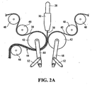
- the cathode or positive electrode film 36 exiting die 30 is deposited between a pair of traveling substrate sheets 38 and 40 supported and driven at constant speed by a pair of flat cylinder rollers 42.
- cathode film 36 is deposited between a current collector sheet 40 and a polypropylene sheet 38.
- Cathode film 36 is deposited directly onto the current collector of the electrochemical cell being produced.
- die 30 is oriented vertically and is positioned as close as possible to the pair of flat cylinder rollers 42.
- the three-layer film 44 is then carried away and rolled up for storage or transported to further processing stations to complete the assembly of the alkali metal polymer electrochemical cell.
- Various cylinders 46 are provided along the path of the substrate films 38 and 40 and the three-layer film 44 to provide the required tension such that the .films remain flat.
- the flat cylinder rollers 42 are maintained at temperatures below the ambient temperature and preferably at a temperature generally ranging from -5 °C to-30 °C.
- Flat cylinder rollers 42 may also be provided with an anti-adhesive liner to prevent such adhesion.
- Flat cylinder rollers 42 are moulted on pivotal support structures 48 and 50, each having an hydraulic cylinder 52 adapted to adjust the position of the cylinder rollers 42 and to also to adjust the pressure applied onto the three-layer film 44 as it passes in between the cylinder rollers 42. It should be expressly understood that other means for adjusting the position of the cylinder rollers 42 and the pressure applied on the three-layer film 44 by the cylinder rollers 42 are contemplated and within the reach of a person skilled in the art, and as such are within the scope of the present invention. Although the cathode film 36 already feature smooth surfaces, the pressure applied by cylinder rollers 42 equalizes the surface finish of both surfaces to provides a smooth and even surface.
- the surface finish or roughness ratio of the extruded cathode material is important to the efficiency of ionic exchange between the electrolyte separator and the cathode of the electrochemical cell to be assembled.
- the ionic exchange efficiency diminishes with the coarseness of the cathode surface.
- the pressure applied on the positive electrode film 36 may also be used to further reduce its thickness.
- the final thickness of the cathode film 36 should be between 25 and 100 micrometers and preferably between 35 and 70
- Cathode film 36 may be extruded at a thickness of up to 250 micrometers, and then reduced by lamination, calendaring, or rolling as is well known in the art to the desired thickness.
- the cathode film 36 is extruded, at at thickness or between 35. and 70 micrometers directly onto substrate 32 of polypropylene or polyethylene or the current collector in the form of aluminum or copper foil.
- the extruded cathode film 36 may also be stretched onto the substrate 32 in order to reduce its final thickness.
- the stretching of the extruded cathode material is achieved by selecting the speed at which the substrate 32 travels at the contact point between the extruded cathode material and the substrate 32 near exit of die 30 such that the speed of substrate 32 exceeds the rate of discharge of the cathode material at the die opening.
- the speed differential between the substrate 32 and the cathode material exiting die 30 will stretch the cathode film 36 thereby reducing its thickness.
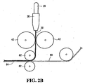
- FIG. 2B illustrates another embodiment of the, continuous manufacturing process of a positive electrode film or cathode film for alkali metal polymer electrochemical cells.
- the cathode film 36 exiting die 30 is deposited directly between flat cylinder rollers 42 that are maintained at cool temperatures. This particular method eliminates any problems that may occur if the substrate films 38 or 40 of the previous embodiment rip or break under the pulling tension exerted by flat cylinder roller 42.
- cathode film 36 exits die 30 in the form of a relatively thin sheet; the sheet 36 is taken up directly by the pair of flat cylinder rollers 42 which equalizers the thickness and surface finish of film 36 to provide a smooth and even surface.
- Flat cylinder rollers 42 may also reduce the thickness of the film 36 to its final thickness of between 35 and 70 micrometers, if the film 36 exits die 30 with a thickness exceeding the target thickness of 35 to 70 micrometers.
- flat cylinder rollers 42 are maintained at temperatures below the ambient temperature and preferably at a temperature ranging from -5 °C to -30 °C to prevent adhesion of the film 36 to the flat cylinder rollers 42.
- Flat cylinder rollers 42 may also be provided with an anti-adhesive liner.
- the film 36 is then laminated onto a substrate 80, preferably a current collector substrate, traveling below flat cylinder rollers 42. The laminate.
- the duration of contact between the extruded cathode film 36 and one of the cooled flat cylinder rollers 42 may be controlled by routing the cathode film 36 around an idle cylinder 46 in order to increase heat transfer efficiency.
- cathode film. 36 remains in contact with one of the cooled cylinder rollers 42 through nearly 180 of rotation of the cooled cylinder rollers 42 thereby increasing the total heat transfer between the cathode film 36 and one of the cooled flat cylinder rollers 42.
- the cathode film 36 obtained via the embodiment illustrated in Figure 2B may also be stretched to reduce its final thickness.
- the stretching of the extruded cathode material is achieved by selecting a rotating speed of the flat cylinder rollers 42 that exceeds the rate of discharge of the cathode material at the die opening.
- the speed differential between the rotating speed of the flat cylinder rollers 42 and the cathode material exiting die 30 will stretch the cathode film 36 thereby further reducing its thickness.
- cathode film 36 is deposited between the current collector and one of the flat cylinder rollers 42 , wherein the cathode film 36 is pressed directly between the surface of the roller 42 on one side and the current collector on the other side.
- the positive electrode material or cathode material as described above is a very difficult material to extrude because of its high solid content, yet the content of active material in solid form in the cathode is relatively important.
- the more active material in the cathode the better the performance of the finished product.
- the polyethylene oxide electrolyte is a binder and does not contribute to the energy content of the electrochemical cell being produced therefrom.
- a high solid content into the polyethylene oxide binder increases the extrusion temperature, the shear stress to which the mixture of cathode material is subjected to, and therefore increases the degradation of the polyethylene oxide binder making it difficult to extrude a positive electrode that will perform tao specification.
- the lithium salt (TFSI) included in the positive electrode material increases ionic conductivity of the cathode but reduces the viscosity of the positive electrode material thereby increasing the difficulty of transporting the positive electrode/cathode slurry through mixing chamber 15, conduit 28 and die 30.
- Typical cathode material for an alkali metal polymer electrochemical cell comprises carbon black as the only electrically conductive filler.
- carbon black has extremely small particles (sub microns).
- the high surface area of these small particles are coated with a substantial portion of the polyethylene oxide binder which has the negative effect of decreasing the solid content of active material which can be absorbed by the polyethylene oxide binder.
- Carbon black particles also create agglomeration of the mixture, thereby increasing the likelihood of blockage in an extruder and generally increasing the viscosity of the mixture.
- Graphite displays an acceptable electronic conductivity and comprises: larger particles having therefore less surface area to be coated by the polyethylene oxide binder with the effect of decreasing the viscosity of the mixture.
- an additive consisting of an ultra fine powder of metal oxide such as silica, aluminum, or titanium oxide with a particle size between 7 and 40 nm as disclosed in US pat No. 5,486,435 and US pat No. 5,622,792 .
- the role of the additive is to prevent or diminish the formation of adhesive solid blocks in the powder mixture in reservoir 34 and to allow its introduction into the second feed throat of the extruder.
- Preferred compositions of ultra fine powders of metal oxide include pyrogenated silica having a BET surface between 50 and 400 m2/g containing more than 99.9% silica in a concentration of less than 10% by weight with respect to the mixture of cathode material.
- plasticizers or lubricants in small quantity may also be included in the polymer to optimize the mixing ability of the components of the cathode mixture and the viscosity of the mixture to facilitate the extrusion of the composite cathode material.
- the extrusion process and the mixture of cathode material described above enables the extrusion of a positive electrode film having a total solid content by weight of between 40 and 80 percent using a commercially available extrusion machine.
- Extruding the cathode material according to the invention provides a cathode having a porosity of less than 10%.
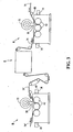
- FIG 3 illustrates another variant of the manufacturing process, in which a single current collector is coated on both sides with a positive electrode or cathode film.
- the current collector thin sheet 70 preferably comprising aluminum, is brought into a first extrusion station "A" comprising an extrusion machine 72 similar to the one depicted in Figures 2A or 2B where a positive electrode film is deposited by die 30 onto a first side of current collector 70.
- the two layer film 74 passes through a pair of rollers 42 which are controlled by either hydraulic or electric actuators 76, and then exits extrusion station "A” .
- the two layer film 74 enters into a station “C” where it is turned upside down such that it exits station "C” with its layer of positive electrode film facing down.
- the face down two layer film 74' is transported into a second extrusion station "B" comprising an extrusion machine 72 where another positive electrode film is deposited by a die 30 onto the second side of the current collector such that both sides of the current collector are coated with a positive electrode film 36.
- the resulting three layer film 74" of current collector / twin positive electrodes then exits the second extrusion station "B” and is either rolled up for storage or transported to further processing stations to complete the assembly of the alkali metal polymer electrochemical cell.
- the cathode material may be extruded through any classical sheet dies, such as those illustrated in Figures 4A to 4D , into a cathode sheet or films.
- the shape of typical sheet dies may come in a variety of designs such as with a fish tail inner configuration or a coat hanger inner configuration.
- a sheet die spreads the flow path of the cathode material over a wide surface and enable to extrude into thin sheets.
- channels may be carved into the die to direct an increased flow of cathode material toward the sides of the die exit to ensure that the cathode sheet being extruded has an even thickness throughout its width.
Landscapes
- Chemical & Material Sciences (AREA)
- Engineering & Computer Science (AREA)
- Chemical Kinetics & Catalysis (AREA)
- Electrochemistry (AREA)
- General Chemical & Material Sciences (AREA)
- Mechanical Engineering (AREA)
- Manufacturing & Machinery (AREA)
- Inorganic Chemistry (AREA)
- Materials Engineering (AREA)
- Crystallography & Structural Chemistry (AREA)
- Fluid Mechanics (AREA)
- Physics & Mathematics (AREA)
- Battery Electrode And Active Subsutance (AREA)
- Secondary Cells (AREA)
- Cell Electrode Carriers And Collectors (AREA)
Abstract
Description
- The present invention generally relates to alkali metal polymer batteries and, more specifically, to positive electrode sheets for alkali metal polymer batteries that are made by a continuous extrusion process for forming solid polymer electrolyte-cathode sheets.
- Rechargeable batteries manufactured from laminates of solid polymer electrolytes and sheet-like electrodes display many advantages over conventional liquid electrolytes batteries. These advantages include: lower overall battery weight, high power density, high specific energy, and longer service life. In addition, they are more environmentally friendly since the danger of spilling toxic liquid into the environment is eliminated.
- Solid polymer battery components generally include: positive electrodes (also referred to as cathodes), negative electrodes (also referred to as anodes), and an insulating material capable of permitting ionic conductivity, such as a solid polymer electrolyte, sandwiched therebetween. The anodes are usually made of light-weight metals foils, such as alkali metals and alloys thereof typically lithium metal, lithium oxide, lithium-aluminum alloys and the like. The composite cathodes are usually formed of a mixture of active material such as a transitional metal oxide, an electrically conductive filler, usually carbon particles, an ionically conductive polymer electrolyte material and a current collector usually a thin sheet of aluminum.
- Composite cathode films are usually obtained by coating onto a current collector a mixture of a solvent and cathode materials with a doctor blade, for instance, and evaporating the solvent. This process is inefficient for the mass production of cathode films and results in cathode films having a relatively high porosity, and therefore decreased density.
- Since solid polymer electrolytes are usually less conductive than liquid polymer electrolytes, solid or dray electrochemical cells must be prepared from very thin films (total thickness of approximately 35 to 250 micrometers to compensate for the lower conductivity, with a high film contact surfaces and provide electrochemical cells with high power density. Solid cathode films must therefore be produced into very thin films of generally ranging from about 35 to 125 micrometers.
- One of the most efficient manufacturing processes for obtaining thin sheets is the process of continuous extrusion.
US Pat. No. 5,725,822 to Keller et al. discloses a method for extruding electrode material by liquid injection. The solid particulate of active electrode materials are partially mixed with a minor portion of the components of the polymer electrolyte and fed into a first feed throat of the extruder while the remaining polymer electrolyte composite, preferably rich in liquid components including at least one solvent, is fed downstream through a second feed throat. The process has been found to provide a composite having a high ratio of solid active material electrode/electrolyte and by separately mixing the components, the electrode composition may be adjusted to provide optimal proportions of all materials for a. given application. However, this process is limited to polymer electrolyte binders capable of withstanding the extrusion processing conditions, in particular the temperature, pressure and shear conditions such as polyacrylonitrile (PAN), polyvinylidene difluoride (PVDF), polyvinylpyrrolidone (PVP) and the like mixed with a solvent. The use of solvents in the extruded mixture results in a thicker composite cathode sheet that displays a high porosity and a rough surface finish. The latter characteristics are generally detrimental to the efficiency of the electrochemical cell produced. -
US Pat. No. 5,316,556 to Morris also discloses an apparatus and method for extruding a cathode in which the cathode material is mixed to an homogenous state, and then transported under constant or increasing shear stress to a point of extrusion such that it is extruded at constant rate. The cathode material disclosed is referred to as a shear thinning material as it exhibits non-Newtonian fluid characteristics; that is its viscosity decreases as the material is subjected to increasing shear stress. The solution proposed to transport the melted 'shear thinning' cathode material smoothly to the extruder exit nozzle is simply to maintain a minimum pressure and therefore a minimum amount of shear stress on the 'shear thinning' cathode material to ensure' that the viscosity or flow resistance of the cathode material remains below a certain value to prevent blockage of the cathode material in the extruder. Experience has shown however that such a simple technique is inadequate for a wide variety of cathode materials, especially when the solid content of the cathode material is above 30% by weight. - Cathode materials having a high solid content of active cathodic material and conductive filler (above 30%) like polymers of the polyether family such as polyethylene oxide having a high percentage of solid particles of vanadium oxide and carbon cannot withstand normal extrusion conditions and, more particularly, high temperatures and high shear conditions. Polyethers have a low melting point (around 50°C) and are chemically unstable under extrusion conditions thereby making them extremely difficult to process through an extruder to form a thin positive electrode composite sheet. Neither Keller et al. nor Morris provide a viable process for extruding cathode thin films made of a polyether binder having a high percentage of solids.
- Thus there is a need for a solid polymer electrolyte-cathode sheet having a high solid content which can be extruded and a method for extruding a cathode sheet having a high solid content.
- Under a first broad aspect, the invention seeks to provide a process for extruding a positive electrode sheet having between 40 % /wt and 80 % /wt of solid content for a lithium metal polymer battery through a single or twin screw extruder. The process comprises:
- a) introducing a polyethylene oxide in a first feed throat of the extruder;
- b) introducing downstream from said first feed throat, a mixture of active cathodic intercalation material, lithium salt, and carbon and graphit as electronic conductive materials, said mixture being introduced in a quantity sufficient to be between 40 % /wt and 80 % /wt of the positive electrode sheet to be produced;
- c) mixing said polyethylene oxide with said mixture introduced in b) into a single or twin screw section of said extruder;
- d) extruding a positive electrode material obtained in c) through a die opening in the form of a thin sheet of between 40 and 200 micrometers, and
- e) calandering or rolling the positive electrode thin sheet to reduce a thickness of said positive electrode sheet thereby reducing the thickness of the positive electrode sheet between 25 micrometers and 125 micrometers and more preferably between about 35 micrometers and about 70 micrometers.
- Under a second broad aspect, the invention further seeks to provide an electrochemical cell comprising a lithium or lithium alloy based negative electrode, a solid polymer electrolyte separator and a positive electrode film. The positive electrode film comprises an ionically conductive polyether electrolyte material, an active cathodic intercalation material, a lithium salt; and carbon and graphite particles as electronically conductive materials in a ratio of carbon/graphite ranging from 0.1:1 to 4:1. The positive electrode film comprises between 40 % /wt and 80 % /wt of active cathodic intercalation material, lithium salt; and Carbon and Graphite, said positive electrode film has a thickness of between 25 micrometers and 125 micrometers.
- Preferably, the positive electrode thin film comprises more than 50 % /wt of active cathodic intercalation material; lithium salt; and Carbon and Graphite particles; the thickness of the positive electrode thin film is between about 35 micrometers and about 125 micrometers and the ratio of Carbon/Graphite ranges from 0.5:1 to 2:1 . Advantageously, the positive electrode tin film further comprises an additive consisting of an ultra fine powder of metal oxide such as fumed silica, aluminum, or titanium oxide with a particle size between 7 and 40 nm.
- Under a third broad aspect, the invention seeks to provide a process for extruding a positive electrode sheet having between 40 % /wt and 80 % /wt of solid content through a single or twin screw extruder. The process comprises: mixing a polymer binder, an active cathode material, and an electronic conductive material into a single or twin screw section of the extruder; extruding a positive electrode material through a die opening in the form of a sheet of between 40 and 200 micrometers; feeding said positive electrode material directly between a pair of rollers and without a substrate; and depositing the positive electrode material onto a substrate traveling near said rollers.
- A detailed description of preferred embodiments of the present invention is provided herein below with reference to the following drawings, in which:
-
Figure 1A is a schematic cross-sectional side view of a typical thin screw extrusion machine illustrating the inner parts and channels of the extrusion machine; -
Figure 1B is a schematic top plan cross-sectional view of a typical twin screw extrusion machine illustrating the inner parts and channels of the extrusion machine; -
Figure 2A is a schematic front view of the extrusion die showing the positive electrode film being extruded onto a substrate; -
Figure 2B is a schematic front view of the extrusion die showing the positive electrode film being extruded directly onto rollers; -
Figure 2C is a schematic front view of the extrusion die showing the positive electrode film being extruded directly onto rollers and routed around one of the rollers. -
Figure 3 is a schematic front view of two extrusion stations; and -
Figure 4A to 4D are schematic top plan views of the inner configuration of typical sheet dies. - In the drawings, preferred embodiments of the invention are illustrated by way of examples. It is to be expressly understood that the description and the drawings are only for the purpose of illustration and as an aid to understanding. They are not intended to be a definition of the limits of the invention.
- With reference to
Figures 1A and 1B , there is shown a typical twinscrew extruding machine 10 having a pair ofscrews electric motors 16. Screws 12 and 14feature threads 20 and acentral shaft 18 having an increasing diameter such that the material being mixed into themixing chamber 15 is intimately mixed and under varying pressure as it is transported in the direction X. Extrudingmachine 10 further comprises afirst feed throat 24 at a first end of themixing chamber 15 and asecond feed throat 26 located approximately near the middle ofmixing chamber 15. Theforward end 17 ofmixing chamber 15 is of conical shape to direct the melted material being transported into agear pump 22 provided to control the flow rate of the melted material exitingmixing chamber 15. On the exit side ofgear pump 22 is an elbow-shaped conduit 28 leading to a die 30 through which the melted material is discharged at constant rate onto a substrate sheet orfilm 32 traveling at constant speed. Commercially available extruding machines featuring single or twin screw design may be used for the mixing and melting process however it has been found that twin screw designed extruding machine provides a. superior mixing of the components of the cathode material. - As shown more specifically in Figure la, vents 23 and 25 are featured along the upper wall of mixing
chamber 15 to eliminate volatile matter still remaining in the polymer during the heating and mixing process. Two vents are depicted in this particular embodiment, however any number of vents may be provided depending on the amount of volatile matter still remaining in the polymer.Vents twin screws vents screws vents vent screws - The cathode or positive electrode material according to the invention preferably includes a mixture of ionically conductive polymer electrolyte material such as polyethylene oxide, active cathodic material such as vanadium oxide, an electrically conductive filler such as carbon and graphite particles, and lithium salt. In a preferred embodiment, the positive electrode material includes between 25%/wt and 30%/wt of polyethylene oxide; between 57%/wt and 67%/wt of vanadium oxide; between 1.5%/wt and 5%/wt of carbon and graphite particles; and between 4%/wt and 10%/wt of lithium salt. A small portion of fumed silica and some antioxidant in minute proportion may also be added to the mixture in some instances.
- Plasticizers or lubricants in small quantity (less than 10%/wt) may also be included in the polymer to enhance mixing of the polymer with the solid content outlined above and/or to reduce the viscosity of the mixture to facilitate the extrusion of the composite cathode material. Plasticizers or lubricants such as polyvinylidene fluoride (PVDF), co-polymer polyvinylidene fluoride/hexafluordisopropanol (PVDF-HFP), polyvinyl fluoride (PVF), polyethylene glycol dimethyl ether, tetraglyme, triglyme, ethylene carbonate, propylene carbonate, EO/PO diglycol and EO/PO monoglycol or distearates may be used to that effect. Preferably, fluoride polymers such as PVDF, PVDF-HFP, and PVF or polyethylene glycol dimethyl ether are added to the polymer in small quantity; these polymers do not significantly reduce the ionic conductivity or the solid character of the cathode material being extruded. Water may also be used as a plasticizer to reduce the viscosity of the compound and ease of mixing of the solid content with the polyethylene oxide in proportion ranging from 0,005% up to 5% and preferably between 0,1% and 0,8%. The water is dissipated in vapor during the mixing and melting process in the mixing
chamber 15. - The vanadium oxide particle size is selected such as to enable an adequate mixture of the vanadium oxide with the polyethylene oxide in mixing
chamber 15. Preferred particle sizes of vanadium oxide range from 0.3 micrometer to 20 micrometers. - As an example, polyethylene oxide is introduced into mixing
chamber 15 through thefirst feed throat 24 where it begins to melt. Vanadium oxide LiV308, carbon and graphite particles in a ratio ranging from 0:1:1 to 4:1 and preferably of 1:1, and optionally an ultra fine powder of fumed silica are pro-mixed intoreservoir 34 and then introduced into mixingchamber 15 through thesecond feed throat 26. Salt based on lithium can be introduce into mixingchamber 15 through thesecond feed throat 26, or may alternatively be introduced through a third feed throat (not shown) located betweenfirst feed throat 24 and second feed throat 26: As well, plasticizers or lubricants as described above may be mixed with the polyethylene oxide prior to introduction into the mixingchamber 15 or may be introduced into mixingchamber 15 throughsecond feed throat 26 with a view of modifying the rheological properties of the slurry such as reducing the viscosity of the cathode slurry and/or promoting the mixing of the solid content with the polyethylene oxide. In mixingchamber 15, the pre-mixed components outlined above are further mixed with the polyethylene oxide through the actions of the twin screws and blended into an homogeneous slurry which is transported under pressure in direction X to theforward end 17 of mixingchamber 15. The slurry is pushed intogear pump 22 which regulates or controls the flow rate of the slurry throughconduit 28 and ultimately though die 30. As the cathode slurry enters die 30, its flow path is reshaped such that the cathode material slurry exits die 30 shaped as a thin film of between 40 and 200 micrometers and is deposited onto athin sheet substrate 32 of polypropylene or polyethylene or a thin metal foil such as an aluminum or copper foil. - As shown in
Figure 2A , in an embodiment of the continuous manufacturing process of a thin film positive electrode for an alkali metal polymer electrochemical cell, the cathode orpositive electrode film 36 exitingdie 30 is deposited between a pair of travelingsubstrate sheets flat cylinder rollers 42. In a preferred embodiment,cathode film 36 is deposited between acurrent collector sheet 40 and apolypropylene sheet 38.Cathode film 36 is deposited directly onto the current collector of the electrochemical cell being produced. Preferably, die 30 is oriented vertically and is positioned as close as possible to the pair offlat cylinder rollers 42. The three-layer film 44 is then carried away and rolled up for storage or transported to further processing stations to complete the assembly of the alkali metal polymer electrochemical cell.Various cylinders 46 are provided along the path of thesubstrate films layer film 44 to provide the required tension such that the .films remain flat. To prevent adhesion of the films or sheets to theflat cylinder rollers 42, the latter are maintained at temperatures below the ambient temperature and preferably at a temperature generally ranging from -5 °C to-30 °C.Flat cylinder rollers 42 may also be provided with an anti-adhesive liner to prevent such adhesion. -
Flat cylinder rollers 42 are moulted onpivotal support structures hydraulic cylinder 52 adapted to adjust the position of thecylinder rollers 42 and to also to adjust the pressure applied onto the three-layer film 44 as it passes in between thecylinder rollers 42. It should be expressly understood that other means for adjusting the position of thecylinder rollers 42 and the pressure applied on the three-layer film 44 by thecylinder rollers 42 are contemplated and within the reach of a person skilled in the art, and as such are within the scope of the present invention. Although thecathode film 36 already feature smooth surfaces, the pressure applied bycylinder rollers 42 equalizes the surface finish of both surfaces to provides a smooth and even surface. The surface finish or roughness ratio of the extruded cathode material is important to the efficiency of ionic exchange between the electrolyte separator and the cathode of the electrochemical cell to be assembled. The ionic exchange efficiency diminishes with the coarseness of the cathode surface. - The pressure applied on the
positive electrode film 36 may also be used to further reduce its thickness. The final thickness of thecathode film 36 should be between 25 and 100 micrometers and preferably between 35 and 70Cathode film 36 may be extruded at a thickness of up to 250 micrometers, and then reduced by lamination, calendaring, or rolling as is well known in the art to the desired thickness. However in a preferred embodiment of the Invention, thecathode film 36 is extruded, at at thickness or between 35. and 70 micrometers directly ontosubstrate 32 of polypropylene or polyethylene or the current collector in the form of aluminum or copper foil. - As a variant of the manufacturing process, the extruded
cathode film 36 may also be stretched onto thesubstrate 32 in order to reduce its final thickness. The stretching of the extruded cathode material is achieved by selecting the speed at which thesubstrate 32 travels at the contact point between the extruded cathode material and thesubstrate 32 near exit of die 30 such that the speed ofsubstrate 32 exceeds the rate of discharge of the cathode material at the die opening. The speed differential between thesubstrate 32 and the cathodematerial exiting die 30 will stretch thecathode film 36 thereby reducing its thickness. -
Figure 2B illustrates another embodiment of the, continuous manufacturing process of a positive electrode film or cathode film for alkali metal polymer electrochemical cells. In this embodiment, thecathode film 36 exitingdie 30 is deposited directly betweenflat cylinder rollers 42 that are maintained at cool temperatures. This particular method eliminates any problems that may occur if thesubstrate films flat cylinder roller 42. As shown inFigure 2B ,cathode film 36 exits die 30 in the form of a relatively thin sheet; thesheet 36 is taken up directly by the pair offlat cylinder rollers 42 which equalizers the thickness and surface finish offilm 36 to provide a smooth and even surface.Flat cylinder rollers 42 may also reduce the thickness of thefilm 36 to its final thickness of between 35 and 70 micrometers, if thefilm 36 exits die 30 with a thickness exceeding the target thickness of 35 to 70 micrometers As previously mentioned,flat cylinder rollers 42 are maintained at temperatures below the ambient temperature and preferably at a temperature ranging from -5 °C to -30 °C to prevent adhesion of thefilm 36 to theflat cylinder rollers 42.Flat cylinder rollers 42 may also be provided with an anti-adhesive liner. Thefilm 36 is then laminated onto asubstrate 80, preferably a current collector substrate, traveling belowflat cylinder rollers 42. The laminate. 84 may then pass between a second pair offlat cylinder rollers 82 to promote adhesion of thecathode film 36 onto thesubstrate 80. As shown inFigure 2C , the duration of contact between the extrudedcathode film 36 and one of the cooledflat cylinder rollers 42 may be controlled by routing thecathode film 36 around anidle cylinder 46 in order to increase heat transfer efficiency. As illustrated inFigure 2C , cathode film. 36 remains in contact with one of the cooledcylinder rollers 42 through nearly 180 of rotation of the cooledcylinder rollers 42 thereby increasing the total heat transfer between thecathode film 36 and one of the cooledflat cylinder rollers 42. - As previously described, the
cathode film 36 obtained via the embodiment illustrated inFigure 2B may also be stretched to reduce its final thickness. The stretching of the extruded cathode material is achieved by selecting a rotating speed of theflat cylinder rollers 42 that exceeds the rate of discharge of the cathode material at the die opening. The speed differential between the rotating speed of theflat cylinder rollers 42 and the cathodematerial exiting die 30 will stretch thecathode film 36 thereby further reducing its thickness. - Another embodiment in which the
cathode film 36 is deposited between the current collector and one of theflat cylinder rollers 42 is also contemplated, wherein thecathode film 36 is pressed directly between the surface of theroller 42 on one side and the current collector on the other side. - The positive electrode material or cathode material as described above is a very difficult material to extrude because of its high solid content, yet the content of active material in solid form in the cathode is relatively important. The more active material in the cathode, the better the performance of the finished product. The polyethylene oxide electrolyte is a binder and does not contribute to the energy content of the electrochemical cell being produced therefrom. However, a high solid content into the polyethylene oxide binder increases the extrusion temperature, the shear stress to which the mixture of cathode material is subjected to, and therefore increases the degradation of the polyethylene oxide binder making it difficult to extrude a positive electrode that will perform tao specification. Furthermore, the lithium salt (TFSI) included in the positive electrode material increases ionic conductivity of the cathode but reduces the viscosity of the positive electrode material thereby increasing the difficulty of transporting the positive electrode/cathode slurry through mixing
chamber 15,conduit 28 and die 30. - Typical cathode material for an alkali metal polymer electrochemical cell comprises carbon black as the only electrically conductive filler. However, carbon black has extremely small particles (sub microns). When mixed into the cathode material, the high surface area of these small particles are coated with a substantial portion of the polyethylene oxide binder which has the negative effect of decreasing the solid content of active material which can be absorbed by the polyethylene oxide binder. Carbon black particles also create agglomeration of the mixture, thereby increasing the likelihood of blockage in an extruder and generally increasing the viscosity of the mixture. Graphite however displays an acceptable electronic conductivity and comprises: larger particles having therefore less surface area to be coated by the polyethylene oxide binder with the effect of decreasing the viscosity of the mixture. Utilising a blend of carbon black/graphite in the cathode material as opposed to only carbon permits a higher solid active material content in the cathode mixture and reduces the overall viscosity and potential blockage of the cathode mixture in the extruder without significantly reducing the electronic conductivity of the cathode.
- Into the mix of cathode material in
reservoir 34, an additive consisting of an ultra fine powder of metal oxide such as silica, aluminum, or titanium oxide with a particle size between 7 and 40 nm as disclosed inUS pat No. 5,486,435 andUS pat No. 5,622,792 , may also be introduced. The role of the additive is to prevent or diminish the formation of adhesive solid blocks in the powder mixture inreservoir 34 and to allow its introduction into the second feed throat of the extruder. Preferred compositions of ultra fine powders of metal oxide include pyrogenated silica having a BET surface between 50 and 400 m2/g containing more than 99.9% silica in a concentration of less than 10% by weight with respect to the mixture of cathode material. - As previously mentioned, plasticizers or lubricants in small quantity (less than 5%/wt) may also be included in the polymer to optimize the mixing ability of the components of the cathode mixture and the viscosity of the mixture to facilitate the extrusion of the composite cathode material.
- The extrusion process and the mixture of cathode material described above enables the extrusion of a positive electrode film having a total solid content by weight of between 40 and 80 percent using a commercially available extrusion machine. Extruding the cathode material according to the invention provides a cathode having a porosity of less than 10%.
-
Figure 3 illustrates another variant of the manufacturing process, in which a single current collector is coated on both sides with a positive electrode or cathode film. The current collectorthin sheet 70, preferably comprising aluminum, is brought into a first extrusion station "A" comprising anextrusion machine 72 similar to the one depicted inFigures 2A or 2B where a positive electrode film is deposited by die 30 onto a first side ofcurrent collector 70. The twolayer film 74 passes through a pair ofrollers 42 which are controlled by either hydraulic orelectric actuators 76, and then exits extrusion station "A" . The twolayer film 74 enters into a station "C" where it is turned upside down such that it exits station "C" with its layer of positive electrode film facing down. The face down two layer film 74' is transported into a second extrusion station "B" comprising anextrusion machine 72 where another positive electrode film is deposited by a die 30 onto the second side of the current collector such that both sides of the current collector are coated with apositive electrode film 36. The resulting threelayer film 74" of current collector / twin positive electrodes then exits the second extrusion station "B" and is either rolled up for storage or transported to further processing stations to complete the assembly of the alkali metal polymer electrochemical cell. - The cathode material may be extruded through any classical sheet dies, such as those illustrated in
Figures 4A to 4D , into a cathode sheet or films. The shape of typical sheet dies may come in a variety of designs such as with a fish tail inner configuration or a coat hanger inner configuration. A sheet die spreads the flow path of the cathode material over a wide surface and enable to extrude into thin sheets. For the extrusion of very thin sheets as described herein, channels may be carved into the die to direct an increased flow of cathode material toward the sides of the die exit to ensure that the cathode sheet being extruded has an even thickness throughout its width. - Although the present invention has been described in relation to particular variations thereof, other variation and modifications are contemplated and are within the scope of the present invention. Therefore the present invention is not to be limited by the above description but is defined by the appended claims.
Claims (27)
- A process for extruding a positive electrode sheet having between 40 % /wt and 80 % /wt of solid content for a lithium metal polymer battery through a single or twin screw extruder, said process comprising:a) introducing a polyethylene oxide in a first feed throat of the extruder;b) introducing downstream from said first feed throat, a mixture of active cathodic intercalation material, lithium salt, and carbon and graphit as electronic conductive materials, said mixture being introduced in a quantity sufficient to be between 40 % /wt and 80 % /wt of the positive electrode sheet to be produced;c) mixing said polyethylene oxide with said mixture introduced in b) into a single or twin screw section of said extruder;d) extruding a positive electrode material obtained in c) through a die opening in the form of a thin sheet of between 40 and 200 micrometers, ande) calandering or rolling said positive electrode thin sheet to reduce a thickness of said positive electrode thin sheet to a thickness of between 25 micrometers and 125 micrometers.
- A process as defined in claim 1, wherein a ratio of said carbon to said graphit ranges from 0.1:1 to 4:1.
- A process as defined in claim 2, wherein the ratio of said carbon to said graphite ranges from 0.5:1 to 2:1.
- A process as defined in any one of claims 1 to 3, further comprising adding a plasticizer or lubricant to said mixture.
- A process as defined in claim 4, wherein said plastisizer or lubricant is selected from the group consisting of: Polyvinylidene fluoride (PVDF), polyvinyl fluoride (PVF), co-polymer polyvinylidene fluoride/hexafluoroisopropanol (PVDF-HFP), polyethylene glycol dimethyl ether, Tridecyl methacrylate, Ethylene Carbonate, Propylene Carbonate, EO/PO diglycol and EO/PO monoglycol, distearates and water.
- A process as defined in any one of claims 1 to 5, wherein said active cathodic intercalation material is a vanadium oxide.
- A process as defined in claim 6, wherein said vanadium oxide is selected from the group consisting of: V205, LiV308, and V6O13
- A process as defined in any one of claims 1 to 7, further comprising the step of depositing said positive electrode material onto a substrate.
- A process as defined in claim 8, wherein said substrate is a sheet of synthetic resin based on a polypropylene film or a polyethylene film.
- A process as defined in claim 8, wherein said substrate is a metal sheet.
- A process as defined in claim 10, wherein said metal sheet is an aluminum sheet.
- A process as defined in any one of claims 1 to 11. wherein said mixture further comprises an additive comprising an ultra fine powder of metal oxide selected from the group consisting of silica. aluminum/or titanium oxide.
- A process as defined in claim 12, wherein said additive comprises particles having a size between 7 and 40 nanometers.
- A process as defined in any one of claims 8 to 13, wherein the thickness of said positive electrode sheet is reduced after depositing said positive electrode material onto said substrate.
- A process as defined in any one of claims 8 to 13, wherein the thickness of said positive electrode sheet is reduced before depositing said positive electrode material onto said substrate.
- A process as defined in any one of claims 8 to 13, wherein said substrate travels at a speed higher than a rate of discharge of said positive electrode material through said die opening such that said positive electrode sheet is stretched onto said substrate.
- A process as defined in claim 16, wherein the thickness of said positive electrode sheet is reduced after depositing said positive electrode material onto said substrate.
- An electrochemical cell comprising a lithium or lithium alloy based negative electrode, a solid polymer electrolyte separator and a positive electrode film, said positive electrode film comprising:- a polyether electrolyte material;- an active cathodic intercalation material;- a lithium salt; and- carbon and graphite as electronically conductive materials in a ratio of carbon/graphite ranging from 0.1:1 to 4:1;wherein said positive electrode film comprises between 40 % /wt and 80 % /wt of said active cathodic intercalation material; lithium salt; and carbon and graphite, and said positive electrode film has a thickness of between 25 micrometers and 125 micrometers.
- A process for extruding a positive electrode sheet having between 40 % /wt and 80 % /wt of solid content through a single of twin screw extruder, said process comprising:a) mixing a polymer binder, an active cathode material, and an electronic conductive material into a single or twin screw section of said extruder;b) extruding a positive electrode material through a die opening in the form of a sheet of between 40 and 200 micrometers;c) feeding said positive electrode material directly between a pair of rollers and without a substrate; andd) depositing said positive electrode material onto a substrate traveling near said rollers.
- A process as defined in claim 19, wherein said rollers are maintained at a temperature below the ambient temperature.
- A process as defined in any one of claims 1 to 17, wherein water is added to the mixture in proportion ranging from 0.005 % up to 5 %.
- A process as defined in claim 21, wherein water is added to the mixture in proportion ranging from 0.1 % to 0.8 %.
- A process as defined in claim 19 or 20, wherein said pair of rollers rotate at a speed higher than a feeding rate of discharge of said positive electrode material through said die opening such that said positive electrode material in the form of a sheet is stretched thereby reducing the thickness of the sheet.
- A process as defined in claim 23, wherein said pair of rollers further reduce the thickness of said positive electrode material in the form of a sheet to a thickness of between 25 micrometers and 100 micrometers by calandering, laminating or rolling the sheet.
- A process as defined in claim 19 or 20, wherein said pair of rollers reduce the thickness of said positive electrode material in the form of a sheet to a thickness of between 25 micrometers and 100 micrometers by calandering, laminating or rolling the sheet.
- A process as defined in any one of claims 20 and 23 to 25, wherein said rollers are maintained at a temperature ranging from -5°C to -30°C.
- A process as defined in any one of claims 20 and 23 to 26, wherein said positive electrode material in the form of a sheet remains in contact with a particular one of said pair of rollers through nearly 180 degrees of the rotation of the particular roller, thereby increasing the total heat transfer between the positive electrode material in the form of a sheet and the particular roller.
Applications Claiming Priority (3)
| Application Number | Priority Date | Filing Date | Title |
|---|---|---|---|
| US36207902P | 2002-03-07 | 2002-03-07 | |
| US362079P | 2002-03-07 | ||
| PCT/CA2003/000319 WO2003075375A2 (en) | 2002-03-07 | 2003-03-07 | Positive electrode films for alkali metal polymer batteries and method for making same |
Publications (2)
| Publication Number | Publication Date |
|---|---|
| EP1479119A2 EP1479119A2 (en) | 2004-11-24 |
| EP1479119B1 true EP1479119B1 (en) | 2012-08-01 |
Family
ID=27789145
Family Applications (1)
| Application Number | Title | Priority Date | Filing Date |
|---|---|---|---|
| EP03704148A Expired - Lifetime EP1479119B1 (en) | 2002-03-07 | 2003-03-07 | Positive electrode films for alkali metal polymer batteries and method for making same |
Country Status (6)
| Country | Link |
|---|---|
| US (2) | US7700018B2 (en) |
| EP (1) | EP1479119B1 (en) |
| JP (1) | JP4593114B2 (en) |
| AU (1) | AU2003206599A1 (en) |
| CA (1) | CA2477318C (en) |
| WO (1) | WO2003075375A2 (en) |
Families Citing this family (45)
| Publication number | Priority date | Publication date | Assignee | Title |
|---|---|---|---|---|
| AU2003206599A1 (en) * | 2002-03-07 | 2003-09-16 | Avestor Limited Partnership | Positive electrode films for alkali metal polymer batteries and method for making same |
| DE60333958D1 (en) * | 2002-04-26 | 2010-10-07 | Zeon Corp | Polyether polymer and process for producing the same |
| JP4470360B2 (en) * | 2002-09-30 | 2010-06-02 | 日本ゼオン株式会社 | Molding material for polymer solid electrolyte, polymer solid electrolyte molded body, and method for producing the same |
| US6939383B2 (en) * | 2002-05-03 | 2005-09-06 | 3M Innovative Properties Company | Method for making electrode |
| JPWO2005001963A1 (en) * | 2003-06-27 | 2006-08-10 | 日本ゼオン株式会社 | Active material for cathode film, polyether polymer composition for cathode film, cathode film, and method for producing cathode film |
| KR100570677B1 (en) * | 2003-09-26 | 2006-04-12 | 삼성에스디아이 주식회사 | Lithium secondary battery |
| US20050236732A1 (en) * | 2004-01-13 | 2005-10-27 | Bernd Brosch | Method and apparatus for making positive electrode films for polymer batteries |
| US8784595B2 (en) * | 2004-07-26 | 2014-07-22 | Bathium Canana Inc. | Process for laminating components of an electrochemical cell |
| JP5149505B2 (en) | 2005-12-22 | 2013-02-20 | グレイトバッチ リミテッド | Cathode collector manufacturing apparatus and method for electrochemical cell using lithium / oxyhalide |
| JP2007305546A (en) * | 2006-05-15 | 2007-11-22 | Sony Corp | Lithium ion battery |
| CA2552282A1 (en) * | 2006-07-18 | 2008-01-18 | Hydro Quebec | Multi-layered live lithium-based material, preparation processes and applications in electrochemical generators |
| US8147916B2 (en) * | 2008-03-07 | 2012-04-03 | Bathium Canada Inc. | Process for making electrodes for lithium based electrochemical cells |
| US8420158B2 (en) * | 2008-03-07 | 2013-04-16 | Bathium Canada Inc. | Process for making electrodes for lithium based electrochemical cells |
| FR2949907B1 (en) | 2009-09-09 | 2011-11-25 | Batscap Sa | PROCESS FOR THE PREPARATION OF A COMPOSITE MATERIAL FOR POSITIVE ELECTRODE BY EXTRUSION IN THE PRESENCE OF AQUEOUS SOLVENT, POSITIVE ELECTRODE OBTAINED BY THE PROCESS AND APPLICATIONS |
| US8448386B2 (en) * | 2009-12-11 | 2013-05-28 | 2Fl Enterprises, Llc | Window remediation system and method |
| US20130214456A1 (en) * | 2010-10-19 | 2013-08-22 | I2Ic Corporation | Apparatus and Method of Manufacturing Objects with Varying Concentration of Particles |
| US10745555B2 (en) * | 2011-06-23 | 2020-08-18 | Solvay Specialty Polymer Italy S.P.A. | Process for manufacturing porous membranes |
| US9484569B2 (en) * | 2012-06-13 | 2016-11-01 | 24M Technologies, Inc. | Electrochemical slurry compositions and methods for preparing the same |
| WO2014080544A1 (en) * | 2012-11-21 | 2014-05-30 | 長野オートメーション株式会社 | Device which sandwiches electrode sheets with separators |
| US9590233B2 (en) | 2013-04-05 | 2017-03-07 | Duracell U.S. Operations, Inc. | Method of making a cathode |
| JP6136917B2 (en) * | 2013-12-26 | 2017-05-31 | トヨタ自動車株式会社 | Continuous extrusion kneader for mixture for electrode active material layer |
| US20160087271A1 (en) * | 2014-09-24 | 2016-03-24 | Schlumberger Technology Corporation | Rechargeable Lithium Polymer Electrolyte Battery for Oilfield Use |
| CN106159318A (en) * | 2015-04-07 | 2016-11-23 | 中国科学院上海硅酸盐研究所 | Novel slice type solid-state serondary lithium battery that garnet-type solid electrolyte supports and preparation method thereof |
| WO2017124098A1 (en) | 2016-01-15 | 2017-07-20 | 24M Technologies, Inc. | Systems and methods for infusion mixing a slurry-based electrode |
| KR102227802B1 (en) * | 2016-10-07 | 2021-03-15 | 주식회사 엘지화학 | Electrode active material slurry composition and secondary battery comprising electrode using the same |
| CN110997750B (en) * | 2017-04-07 | 2022-08-23 | 罗伯特·博世有限公司 | Diester-based polymer electrolyte for high voltage lithium ion batteries |
| US10367228B2 (en) | 2017-04-07 | 2019-07-30 | Seeo, Inc. | Diester-based polymer electrolytes for high voltage lithium ion batteries |
| CN107565090A (en) * | 2017-08-30 | 2018-01-09 | 清陶(昆山)能源发展有限公司 | A kind of positive plate of lithium battery and preparation method thereof |
| CN107591536B (en) * | 2017-09-02 | 2020-08-11 | 清陶(昆山)能源发展有限公司 | Gel composite positive plate, preparation method thereof and method for preparing all-solid-state lithium battery |
| KR102536633B1 (en) | 2018-03-14 | 2023-05-25 | 주식회사 엘지에너지솔루션 | Method for manufacturing positive electrode |
| JP7525984B2 (en) * | 2018-05-30 | 2024-07-31 | 三洋化成工業株式会社 | Manufacturing method for electrode active material layer, manufacturing method for lithium ion battery electrode, and manufacturing method for lithium ion battery |
| CN109605787A (en) * | 2018-10-27 | 2019-04-12 | 上海骋润高分子材料有限公司 | The processing method of PTFE membrane |
| WO2020203883A1 (en) | 2019-03-29 | 2020-10-08 | 日本ゼオン株式会社 | Method for producing electrode for electrochemical devices, method for producing electrochemical device, and molding material for electrodes |
| US12444745B2 (en) | 2019-03-29 | 2025-10-14 | Zeon Corporation | Shaping material for electrode, electrode and methods of producing and recycling same, and electrochemical device |
| US11996540B2 (en) * | 2019-12-20 | 2024-05-28 | Intecells, Inc. | Method and apparatus for making lithium ion battery electrodes |
| US11621411B2 (en) | 2019-12-23 | 2023-04-04 | Intecells, Inc. | Method of insulating lithium ion electrochemical cell components with metal oxide coatings |
| CN112428554A (en) * | 2020-10-29 | 2021-03-02 | 青海百能汇通新能源科技有限公司 | Carbon felt composite battery pole plate and production method thereof, carbon felt composite calendering equipment and flow battery |
| JP7213275B2 (en) * | 2021-01-08 | 2023-01-26 | 日本碍子株式会社 | Extrusion dies and extruders |
| WO2022164120A1 (en) * | 2021-01-27 | 2022-08-04 | 주식회사 엘지에너지솔루션 | Free-standing film for dry electrode, manufacturing apparatus thereof, dry electrode including same, and secondary battery |
| CN113102188B (en) * | 2021-04-26 | 2025-05-27 | 般若涅利(北京)装备技术有限公司 | Slurry double-sided coating device |
| JP7155360B1 (en) | 2021-08-02 | 2022-10-18 | 株式会社日本製鋼所 | Reactor, reaction system, material manufacturing system, battery material manufacturing system, battery manufacturing system, reaction product manufacturing method, battery material manufacturing method, and battery manufacturing method |
| JP2023148643A (en) * | 2022-03-30 | 2023-10-13 | Apb株式会社 | Electrode manufacturing apparatus for battery and electrode manufacturing method for battery |
| CN115101721B (en) * | 2022-07-29 | 2023-06-02 | 广东利元亨智能装备股份有限公司 | A method and device for forming an electrode film, and a method and device for manufacturing a pole piece |
| DE112024002895A5 (en) * | 2023-07-10 | 2026-04-23 | Troester Gmbh & Co. Kg | Method for producing a solvent-free electrode compound and a method for dispensing a template using a dispensing device |
| KR20250076092A (en) * | 2023-11-22 | 2025-05-29 | 삼성에스디아이 주식회사 | Apparatus and method for manufacturing electrode and the electrode |
Family Cites Families (25)
| Publication number | Priority date | Publication date | Assignee | Title |
|---|---|---|---|---|
| US205835A (en) * | 1878-07-09 | Improvement in wagon-racks | ||
| US4320184A (en) * | 1981-01-19 | 1982-03-16 | Mpd Technology Corporation | Production of a cell electrode system |
| US4502903A (en) * | 1982-01-20 | 1985-03-05 | Polaroid Corporation | Method of making lithium batteries with laminar anodes |
| FR2553937A1 (en) | 1983-10-20 | 1985-04-26 | Schwob Yvan | Electrode made of carbon bonded by a thermoplastic resin. |
| US5143805A (en) | 1986-03-24 | 1992-09-01 | W. R. Grace & Co.-Conn: | Cathodic electrode |
| ES2048727T3 (en) * | 1986-03-24 | 1994-04-01 | Grace W R & Co | CATHODIC ELECTRODE. |
| US5277729A (en) * | 1989-03-08 | 1994-01-11 | Murata Manufacturing Co., Ltd. | Method of manufacturing polarizable electrode for electric double-layer capacitor |
| US4976904A (en) | 1989-04-20 | 1990-12-11 | Energy Research Corporation | Method and apparatus for continuous formation of fibrillated polymer binder electrode component |
| US5240655A (en) * | 1991-12-20 | 1993-08-31 | W. R. Grace & Co.-Conn. | Process of making a battery separator |
| US5346385A (en) * | 1992-10-29 | 1994-09-13 | Valence Technology, Inc. | Chilled roller apparatus for achieving desired surface roughness characteristics of an electrode material on a web |
| US5334334A (en) * | 1993-03-30 | 1994-08-02 | Valence Technology, Inc. | Method of preparing lithium battery electrode compositions |
| US5316556A (en) | 1993-03-30 | 1994-05-31 | Valence Technology, Inc. | Apparatus and method for extruding shear thinning material |
| US5482587A (en) * | 1993-06-16 | 1996-01-09 | Valence Technology, Inc. | Method for forming a laminate having a smooth surface for use in polymer electrolyte batteries |
| DE19642878A1 (en) * | 1995-10-31 | 1997-05-07 | Basf Magnetics Holding Gmbh | Electrode materials suitable for electrochemical cells, comprising a fluorine=free polymeric binder and a solid material capable of reversibly taking up or releasing lithium ions |
| JPH09199113A (en) * | 1996-01-23 | 1997-07-31 | Toshiba Battery Co Ltd | Polymer electrolyte secondary cell |
| US5749927A (en) | 1996-05-24 | 1998-05-12 | W. R. Grace & Co. -Conn. | Continuous process to produce lithium-polymer batteries |
| US5725822A (en) | 1996-05-24 | 1998-03-10 | W. R. Grace & Co.-Conn. | Extrusion of electrode material by liquid injection into extruder barrel |
| JP2002542574A (en) * | 1999-02-19 | 2002-12-10 | アムテック リサーチ インターナショナル エルエルシー | Conductive self-supporting microporous polymer sheet |
| WO2000052085A1 (en) | 1999-03-03 | 2000-09-08 | E.I. Du Pont De Nemours And Company | Continuous melt process for fabricating ionically conductive articles |
| US20030062259A1 (en) * | 1999-05-10 | 2003-04-03 | Naofumi Mushiake | Electrochemical device and process for manufacturing same |
| US6368365B1 (en) * | 2000-03-23 | 2002-04-09 | The Gillette Company | Method of making a battery |
| US6589299B2 (en) * | 2001-02-13 | 2003-07-08 | 3M Innovative Properties Company | Method for making electrode |
| DE10115210B4 (en) | 2001-02-14 | 2007-02-08 | Dilo Trading Ag | Use of special polymers as adhesion promoters for lithium batteries and lithium polymer battery |
| AU2003206599A1 (en) * | 2002-03-07 | 2003-09-16 | Avestor Limited Partnership | Positive electrode films for alkali metal polymer batteries and method for making same |
| EP1665416B1 (en) * | 2003-08-01 | 2014-04-30 | Bathium Canada Inc. | Cathode material for polymer batteries and method of preparing same |
-
2003
- 2003-03-07 AU AU2003206599A patent/AU2003206599A1/en not_active Abandoned
- 2003-03-07 EP EP03704148A patent/EP1479119B1/en not_active Expired - Lifetime
- 2003-03-07 WO PCT/CA2003/000319 patent/WO2003075375A2/en not_active Ceased
- 2003-03-07 JP JP2003573720A patent/JP4593114B2/en not_active Expired - Lifetime
- 2003-03-07 US US10/382,539 patent/US7700018B2/en not_active Expired - Fee Related
- 2003-03-07 CA CA2477318A patent/CA2477318C/en not_active Expired - Lifetime
- 2003-09-23 US US10/668,937 patent/US20040130061A1/en not_active Abandoned
Also Published As
| Publication number | Publication date |
|---|---|
| JP2005519442A (en) | 2005-06-30 |
| JP4593114B2 (en) | 2010-12-08 |
| WO2003075375A2 (en) | 2003-09-12 |
| EP1479119A2 (en) | 2004-11-24 |
| WO2003075375A3 (en) | 2003-12-04 |
| AU2003206599A8 (en) | 2003-09-16 |
| US20040130061A1 (en) | 2004-07-08 |
| CA2477318A1 (en) | 2003-09-12 |
| US7700018B2 (en) | 2010-04-20 |
| AU2003206599A1 (en) | 2003-09-16 |
| US20030215710A1 (en) | 2003-11-20 |
| CA2477318C (en) | 2011-07-19 |
Similar Documents
| Publication | Publication Date | Title |
|---|---|---|
| EP1479119B1 (en) | Positive electrode films for alkali metal polymer batteries and method for making same | |
| US6939383B2 (en) | Method for making electrode | |
| US20050236732A1 (en) | Method and apparatus for making positive electrode films for polymer batteries | |
| US6589299B2 (en) | Method for making electrode | |
| EP1568090B1 (en) | Co-extrusion manufacturing process of thin film electrochemical cell for lithium polymer batteries | |
| US5772934A (en) | Process to produce lithium-polymer batteries | |
| US5725822A (en) | Extrusion of electrode material by liquid injection into extruder barrel | |
| US9450231B2 (en) | Method for preparing a positive electrode material through extrusion in presence of an aqueous solvent, positive electrode obtained through said method, and uses thereof | |
| KR102707066B1 (en) | Free standing film for dry electrode, manufacturing apparatus thereof, dry electrode including the same, and secondary battery | |
| EP2801121B1 (en) | Method of manufacturing multiple fuel cell separator plate assemblies | |
| KR102839462B1 (en) | Free standing film for dry electrode, manufacturing apparatus thereof, dry electrode including the same, and secondary battery | |
| US11515571B2 (en) | Hot melt extruded solid state battery components | |
| EP3849773B1 (en) | Method and device for producing a polymer film | |
| US8784595B2 (en) | Process for laminating components of an electrochemical cell | |
| JP2002124265A (en) | Conductive resin sheet for battery electrode and method for producing the same | |
| WO2022263555A2 (en) | Method for preparing a solvent-free electrode and electrode formulations obtainable by said method |
Legal Events
| Date | Code | Title | Description |
|---|---|---|---|
| PUAI | Public reference made under article 153(3) epc to a published international application that has entered the european phase |
Free format text: ORIGINAL CODE: 0009012 |
|
| 17P | Request for examination filed |
Effective date: 20040907 |
|
| AK | Designated contracting states |
Kind code of ref document: A2 Designated state(s): AT BE BG CH CY CZ DE DK EE ES FI FR GB GR HU IE IT LI LU MC NL PT RO SE SI SK TR |
|
| AX | Request for extension of the european patent |
Extension state: AL LT LV MK RO |
|
| 17Q | First examination report despatched |
Effective date: 20080627 |
|
| RAP1 | Party data changed (applicant data changed or rights of an application transferred) |
Owner name: BATHIUM CANADA INC. |
|
| GRAP | Despatch of communication of intention to grant a patent |
Free format text: ORIGINAL CODE: EPIDOSNIGR1 |
|
| RIC1 | Information provided on ipc code assigned before grant |
Ipc: B32B 37/15 20060101ALI20120109BHEP Ipc: H01M 4/66 20060101ALI20120109BHEP Ipc: H01M 4/04 20060101ALI20120109BHEP Ipc: B32B 37/00 20060101ALI20120109BHEP Ipc: B32B 37/10 20060101ALI20120109BHEP Ipc: H01M 4/62 20060101AFI20120109BHEP Ipc: B29C 47/14 20060101ALI20120109BHEP Ipc: H01M 4/58 20100101ALI20120109BHEP Ipc: H01M 4/485 20100101ALI20120109BHEP |
|
| GRAS | Grant fee paid |
Free format text: ORIGINAL CODE: EPIDOSNIGR3 |
|
| GRAA | (expected) grant |
Free format text: ORIGINAL CODE: 0009210 |
|
| AK | Designated contracting states |
Kind code of ref document: B1 Designated state(s): AT BE BG CH CY CZ DE DK EE ES FI FR GB GR HU IE IT LI LU MC NL PT RO SE SI SK TR |
|
| REG | Reference to a national code |
Ref country code: GB Ref legal event code: FG4D |
|
| REG | Reference to a national code |
Ref country code: CH Ref legal event code: EP Ref country code: AT Ref legal event code: REF Ref document number: 569072 Country of ref document: AT Kind code of ref document: T Effective date: 20120815 |
|
| REG | Reference to a national code |
Ref country code: IE Ref legal event code: FG4D |
|
| REG | Reference to a national code |
Ref country code: DE Ref legal event code: R096 Ref document number: 60341651 Country of ref document: DE Effective date: 20120920 |
|
| REG | Reference to a national code |
Ref country code: NL Ref legal event code: VDEP Effective date: 20120801 |
|
| REG | Reference to a national code |
Ref country code: AT Ref legal event code: MK05 Ref document number: 569072 Country of ref document: AT Kind code of ref document: T Effective date: 20120801 |
|
| PG25 | Lapsed in a contracting state [announced via postgrant information from national office to epo] |
Ref country code: CY Free format text: LAPSE BECAUSE OF FAILURE TO SUBMIT A TRANSLATION OF THE DESCRIPTION OR TO PAY THE FEE WITHIN THE PRESCRIBED TIME-LIMIT Effective date: 20120801 Ref country code: AT Free format text: LAPSE BECAUSE OF FAILURE TO SUBMIT A TRANSLATION OF THE DESCRIPTION OR TO PAY THE FEE WITHIN THE PRESCRIBED TIME-LIMIT Effective date: 20120801 Ref country code: FI Free format text: LAPSE BECAUSE OF FAILURE TO SUBMIT A TRANSLATION OF THE DESCRIPTION OR TO PAY THE FEE WITHIN THE PRESCRIBED TIME-LIMIT Effective date: 20120801 |
|
| PG25 | Lapsed in a contracting state [announced via postgrant information from national office to epo] |
Ref country code: SI Free format text: LAPSE BECAUSE OF FAILURE TO SUBMIT A TRANSLATION OF THE DESCRIPTION OR TO PAY THE FEE WITHIN THE PRESCRIBED TIME-LIMIT Effective date: 20120801 Ref country code: SE Free format text: LAPSE BECAUSE OF FAILURE TO SUBMIT A TRANSLATION OF THE DESCRIPTION OR TO PAY THE FEE WITHIN THE PRESCRIBED TIME-LIMIT Effective date: 20120801 Ref country code: BE Free format text: LAPSE BECAUSE OF FAILURE TO SUBMIT A TRANSLATION OF THE DESCRIPTION OR TO PAY THE FEE WITHIN THE PRESCRIBED TIME-LIMIT Effective date: 20120801 Ref country code: PT Free format text: LAPSE BECAUSE OF FAILURE TO SUBMIT A TRANSLATION OF THE DESCRIPTION OR TO PAY THE FEE WITHIN THE PRESCRIBED TIME-LIMIT Effective date: 20121203 Ref country code: GR Free format text: LAPSE BECAUSE OF FAILURE TO SUBMIT A TRANSLATION OF THE DESCRIPTION OR TO PAY THE FEE WITHIN THE PRESCRIBED TIME-LIMIT Effective date: 20121102 |
|
| PG25 | Lapsed in a contracting state [announced via postgrant information from national office to epo] |
Ref country code: NL Free format text: LAPSE BECAUSE OF FAILURE TO SUBMIT A TRANSLATION OF THE DESCRIPTION OR TO PAY THE FEE WITHIN THE PRESCRIBED TIME-LIMIT Effective date: 20120801 |
|
| PG25 | Lapsed in a contracting state [announced via postgrant information from national office to epo] |
Ref country code: EE Free format text: LAPSE BECAUSE OF FAILURE TO SUBMIT A TRANSLATION OF THE DESCRIPTION OR TO PAY THE FEE WITHIN THE PRESCRIBED TIME-LIMIT Effective date: 20120801 Ref country code: ES Free format text: LAPSE BECAUSE OF FAILURE TO SUBMIT A TRANSLATION OF THE DESCRIPTION OR TO PAY THE FEE WITHIN THE PRESCRIBED TIME-LIMIT Effective date: 20121112 Ref country code: CZ Free format text: LAPSE BECAUSE OF FAILURE TO SUBMIT A TRANSLATION OF THE DESCRIPTION OR TO PAY THE FEE WITHIN THE PRESCRIBED TIME-LIMIT Effective date: 20120801 Ref country code: RO Free format text: LAPSE BECAUSE OF FAILURE TO SUBMIT A TRANSLATION OF THE DESCRIPTION OR TO PAY THE FEE WITHIN THE PRESCRIBED TIME-LIMIT Effective date: 20120801 Ref country code: DK Free format text: LAPSE BECAUSE OF FAILURE TO SUBMIT A TRANSLATION OF THE DESCRIPTION OR TO PAY THE FEE WITHIN THE PRESCRIBED TIME-LIMIT Effective date: 20120801 |
|
| PG25 | Lapsed in a contracting state [announced via postgrant information from national office to epo] |
Ref country code: SK Free format text: LAPSE BECAUSE OF FAILURE TO SUBMIT A TRANSLATION OF THE DESCRIPTION OR TO PAY THE FEE WITHIN THE PRESCRIBED TIME-LIMIT Effective date: 20120801 |
|
| PLBE | No opposition filed within time limit |
Free format text: ORIGINAL CODE: 0009261 |
|
| STAA | Information on the status of an ep patent application or granted ep patent |
Free format text: STATUS: NO OPPOSITION FILED WITHIN TIME LIMIT |
|
| 26N | No opposition filed |
Effective date: 20130503 |
|
| PG25 | Lapsed in a contracting state [announced via postgrant information from national office to epo] |
Ref country code: BG Free format text: LAPSE BECAUSE OF FAILURE TO SUBMIT A TRANSLATION OF THE DESCRIPTION OR TO PAY THE FEE WITHIN THE PRESCRIBED TIME-LIMIT Effective date: 20121101 |
|
| REG | Reference to a national code |
Ref country code: DE Ref legal event code: R097 Ref document number: 60341651 Country of ref document: DE Effective date: 20130503 |
|
| PG25 | Lapsed in a contracting state [announced via postgrant information from national office to epo] |
Ref country code: MC Free format text: LAPSE BECAUSE OF NON-PAYMENT OF DUE FEES Effective date: 20130331 |
|
| REG | Reference to a national code |
Ref country code: CH Ref legal event code: PL |
|
| REG | Reference to a national code |
Ref country code: IE Ref legal event code: MM4A |
|
| PG25 | Lapsed in a contracting state [announced via postgrant information from national office to epo] |
Ref country code: LI Free format text: LAPSE BECAUSE OF NON-PAYMENT OF DUE FEES Effective date: 20130331 Ref country code: IE Free format text: LAPSE BECAUSE OF NON-PAYMENT OF DUE FEES Effective date: 20130307 Ref country code: CH Free format text: LAPSE BECAUSE OF NON-PAYMENT OF DUE FEES Effective date: 20130331 |
|
| PG25 | Lapsed in a contracting state [announced via postgrant information from national office to epo] |
Ref country code: TR Free format text: LAPSE BECAUSE OF FAILURE TO SUBMIT A TRANSLATION OF THE DESCRIPTION OR TO PAY THE FEE WITHIN THE PRESCRIBED TIME-LIMIT Effective date: 20120801 |
|
| PG25 | Lapsed in a contracting state [announced via postgrant information from national office to epo] |
Ref country code: LU Free format text: LAPSE BECAUSE OF NON-PAYMENT OF DUE FEES Effective date: 20130307 Ref country code: HU Free format text: LAPSE BECAUSE OF FAILURE TO SUBMIT A TRANSLATION OF THE DESCRIPTION OR TO PAY THE FEE WITHIN THE PRESCRIBED TIME-LIMIT; INVALID AB INITIO Effective date: 20030307 |
|
| REG | Reference to a national code |
Ref country code: FR Ref legal event code: PLFP Year of fee payment: 14 |
|
| REG | Reference to a national code |
Ref country code: FR Ref legal event code: PLFP Year of fee payment: 15 |
|
| REG | Reference to a national code |
Ref country code: FR Ref legal event code: PLFP Year of fee payment: 16 |
|
| PGFP | Annual fee paid to national office [announced via postgrant information from national office to epo] |
Ref country code: GB Payment date: 20220225 Year of fee payment: 20 Ref country code: DE Payment date: 20220217 Year of fee payment: 20 |
|
| PGFP | Annual fee paid to national office [announced via postgrant information from national office to epo] |
Ref country code: IT Payment date: 20220217 Year of fee payment: 20 Ref country code: FR Payment date: 20220221 Year of fee payment: 20 |
|
| REG | Reference to a national code |
Ref country code: DE Ref legal event code: R071 Ref document number: 60341651 Country of ref document: DE |
|
| REG | Reference to a national code |
Ref country code: GB Ref legal event code: PE20 Expiry date: 20230306 |
|
| PG25 | Lapsed in a contracting state [announced via postgrant information from national office to epo] |
Ref country code: GB Free format text: LAPSE BECAUSE OF EXPIRATION OF PROTECTION Effective date: 20230306 |