EP1477876A1 - Electronic equipment - Google Patents
Electronic equipment Download PDFInfo
- Publication number
- EP1477876A1 EP1477876A1 EP04002162A EP04002162A EP1477876A1 EP 1477876 A1 EP1477876 A1 EP 1477876A1 EP 04002162 A EP04002162 A EP 04002162A EP 04002162 A EP04002162 A EP 04002162A EP 1477876 A1 EP1477876 A1 EP 1477876A1
- Authority
- EP
- European Patent Office
- Prior art keywords
- mounting
- crashable
- operation tool
- electronic equipment
- knob
- Prior art date
- Legal status (The legal status is an assumption and is not a legal conclusion. Google has not performed a legal analysis and makes no representation as to the accuracy of the status listed.)
- Granted
Links
Images


Classifications
-
- H—ELECTRICITY
- H01—ELECTRIC ELEMENTS
- H01H—ELECTRIC SWITCHES; RELAYS; SELECTORS; EMERGENCY PROTECTIVE DEVICES
- H01H3/00—Mechanisms for operating contacts
- H01H3/02—Operating parts, i.e. for operating driving mechanism by a mechanical force external to the switch
- H01H3/08—Turn knobs
- H01H3/10—Means for securing to shaft of driving mechanism
-
- B—PERFORMING OPERATIONS; TRANSPORTING
- B60—VEHICLES IN GENERAL
- B60R—VEHICLES, VEHICLE FITTINGS, OR VEHICLE PARTS, NOT OTHERWISE PROVIDED FOR
- B60R21/00—Arrangements or fittings on vehicles for protecting or preventing injuries to occupants or pedestrians in case of accidents or other traffic risks
- B60R21/02—Occupant safety arrangements or fittings, e.g. crash pads
- B60R21/055—Padded or energy-absorbing fittings, e.g. seat belt anchors
-
- H—ELECTRICITY
- H01—ELECTRIC ELEMENTS
- H01H—ELECTRIC SWITCHES; RELAYS; SELECTORS; EMERGENCY PROTECTIVE DEVICES
- H01H3/00—Mechanisms for operating contacts
- H01H3/02—Operating parts, i.e. for operating driving mechanism by a mechanical force external to the switch
- H01H2003/026—Operating parts, i.e. for operating driving mechanism by a mechanical force external to the switch specially adapted to avoid injury to occupants of a car during an accident
-
- H—ELECTRICITY
- H01—ELECTRIC ELEMENTS
- H01H—ELECTRIC SWITCHES; RELAYS; SELECTORS; EMERGENCY PROTECTIVE DEVICES
- H01H3/00—Mechanisms for operating contacts
- H01H3/02—Operating parts, i.e. for operating driving mechanism by a mechanical force external to the switch
- H01H2003/0286—Operating parts, i.e. for operating driving mechanism by a mechanical force external to the switch having a weak point breaking or uncoupling on abnormal external force
-
- Y—GENERAL TAGGING OF NEW TECHNOLOGICAL DEVELOPMENTS; GENERAL TAGGING OF CROSS-SECTIONAL TECHNOLOGIES SPANNING OVER SEVERAL SECTIONS OF THE IPC; TECHNICAL SUBJECTS COVERED BY FORMER USPC CROSS-REFERENCE ART COLLECTIONS [XRACs] AND DIGESTS
- Y10—TECHNICAL SUBJECTS COVERED BY FORMER USPC
- Y10T—TECHNICAL SUBJECTS COVERED BY FORMER US CLASSIFICATION
- Y10T74/00—Machine element or mechanism
- Y10T74/20—Control lever and linkage systems
- Y10T74/20576—Elements
- Y10T74/20732—Handles
- Y10T74/20834—Hand wheels
- Y10T74/2084—Knob or dial
Definitions
- the invention relates to an electronic equipment such as a car audio and, in particular, to an electronic equipment including an operation tool structured such that it can be crashed against an impact.
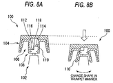
- FIGs. 8A and 8B show an example of an operation tool in a related art.
- An operation tool 100 is a volume knob of a car audio and is supported by an encoder 102 which is used to detect the angle of the knob.
- Fig. 8A shows the operation tool 100 in its normal state and Fig. 8B shows the operation tool 100 when it is crashed.
- the operation tool 100 is composed of an outer knob 104 and an inner knob 106 which are both made of resin.
- the outer knob 104 has a cylindrical shape, while it can be picked up and rotated by an operator.
- the inner knob 106 is fitted with the inside of the outer knob 104.
- the inner knob 106 includes a mounting portion 108 to be mounted on the encoder 102.
- the mounting portion 108 has a tube portion 110 which can be fitted with the outside of the encoder 102.
- the tube portion 110 has an engaging projection 112 for prevention of removal, while the engaging projection 112 can be engaged with the encoder 102.
- the tube portion 110 includes, on its inner surface, two crashable projections 112, 114.
- the crashable projections 112, 114 are disposed at positions which correspond to the stepped end faces 116, 118 of the encoder 102, while they can be contacted with these end faces 116, 118.
- the crashing function means a function by which, in a collision, the operation tool can be crashed and the projection of the operation tool can be thereby reduced as required.
- the mounting function means a function by which the operation tool can be supported positively, that is, the shaking motion of the operation tool can be controlled within the required range.
- the crashable projections 112, 114 are broken in the mounting portion 108 to thereby remove the mounting of the mounting portion 108 with respect to the encoder 102, so that the mounting portion 108 moves toward the encoder 102 and the whole of the operation tool 100 also moves toward the encoder 102. That is, to secure the crashing function, removal of the mounting of the mounting portion 108 due to the crash of the crashable projections 112, 114 is necessary, which limits the strength of this mounting portion 108. Accordingly, there is a limit on the reinforcement of the mounting portion 108 from the viewpoint of prevention of the shaking motion of the operation tool.
- the tube portion 110 advances while spreading in a trumpet manner.
- the tube portion 110 does not cause such trumpet-like spreading deformation, the tube portion 110 will be butted against the encoder 102. Therefore, to secure the crashing function, the tube portion 110 must be weak to such a degree that the above-mentioned spreading deformation is possible. Specifically, the thickness of the tube portion 110 is limited. Therefore, there is a limit on the enhancement in the rigidity of the tube portion 110 from the viewpoint of prevention of the shaking motion.
- the mounting and crashing portions are formed integral with each other, whereas the requirements for the mounting and crashing functions do not agree with each other. And, there exists a trade-off relationship that, in case where one of the two functions is enhanced, the other function is degraded. This means that, in some cases, the two functions are difficult to be compatible. Also, in case where much importance is attached to the crashing function for enhancement in the occupant safety, it is difficult to enhance the mounting function, so that it is sometimes not easy to.reduce the shaking feeling of the operation tool.
- the present invention aims at eliminating the drawbacks found in the above-mentioned electronic equipment of the related art. Accordingly, it is an object of the invention to provide an electronic equipment which not only can secure the sufficient crashing function of the operation tool but also can enhance the mounting function thereof.
- an electronic equipment including an operation tool to be mounted on a support member, wherein the operation tool has an operation portion to be operated by an operator; a mounting portion formed spaced apart from the operation portion in a direction where an impact is applied to the operation tool, the mounting portion being arranged to be mounted on the support member; and a crashable connecting portion for connecting together the operation portion and the mounting portion and also for allowing the operation portion to move with respect to the mounting portion by that said crashable connecting portion is crashed due to an impact given to the operation portion.
- the portion..of the operation tool for fulfilling the crashing function is separated from the mounting portion thereof.
- the operation portion is allowed to move with respect to the mounting portion, thereby allowing the operation portion to be dented.
- the mounting portion is positively mounted on the support member, the above-mentioned denting operation can be carried out properly. Thanks to this, while securing the crashing function, the mounting function can be enhanced.
- the crashable connecting portion is formed so as to extend radially from the mounting portion mounted on a shaft and is connected to the operation portion.
- the crashable connecting portion can be structured such that it is strong in a direction perpendicular to the shaft and is weak in the axial direction, that is, in the crashing direction.
- the radially extending crashable connecting portion may be perpendicular or oblique to the shaft.
- the crashable connecting portion includes two or more bridge portions which are formed radially in a clearance existing between the mounting portion and operation portion so as to connect together these two portions.
- the crashable connecting portion can be structured such that it is properly weak in the axial direction, that is, in the crashing direction.
- each of the bridge portions has a section shape the thickness of which in a direction along the shaft is smaller than the width thereof in a direction perpendicular to the shaft.
- the crashable connecting portion has a bent portion between the mounting portion and operation portion.
- the bent portion may also be formed in the bridge portion.
- the crashable connecting portion has a cut-away portion between the mounting portion and operation portion.
- a typical example of the cut-away portion is a groove.
- the groove may be formed when the operation tool is molded of resin.
- the cut-away portion may be composed of a slit.
- an electronic equipment comprises an outside piece including an outer tube portion constituting the operation portion and an inside piece including an inner tube portion to be fitted with the outer tube portion, and the inside piece has a structure that the inner tube portion and mounting portion situated on the inner peripheral side thereof are connected together by the crashable connecting portion.
- a reference numeral 1 refers to an electronic equipment; 3 to an. operation tool; 5 to an encoder; 7 to a rotation axis; 9 to an Outer knob; 11 to an inner knob; 13 to an outside cylindrical portion; 15 to a front plate portion; 17 to an inside cylindrical portion; 19 to a mounting cylindrical portion; 21 to a crashable connecting portion; 23 to a knob mounting shaft; 25 to an engaging projection; 27 to engaging groove; 29 to a ring-shaped plate portion; 31 to a bridge portion; 33 to a clearance; and 35 to a bent portion.
- Figs. 1 to 3C show an operation tool according to an embodiment of the invention
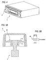
- Fig. 4 shows an electronic equipment into which the present operation tool is incorporated.
- an electronic equipment 1 is a car audio
- an operation tool 3 is a volume knob of the car audio.
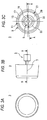
- Figs. 3A to 3C are external views of the operation tool 3.
- Figs. 1 and 2 are respectively sectional views taken along the line A-A and line B-B shown in Figs. 3B and 3C.
- the operation tool 3 is supported on an encoder 5 which is a support member for detecting the rotation angle of the operation tool 3, and can be rotated about the rotation axis 7 of the encoder 5.
- the operation tool 3 has a two-piece structure which is composed of an outer knob 9 made of resin serving as an operation portion and an inner knob 11 serving as a mounting portion.
- the outer knob 9 corresponds to the outside makeup portion of the operation tool 3 and has a cap-like shape composed of an outside cylindrical portion 13 and a front plate portion 15. And, the front plate portion 15 of the outer knob 9 is situated on the front surface of the operation tool and faces an operator.
- the inner knob 11 is composed of an inside cylindrical portion 17, a mounting cylindrical portion 19 and a crashable connecting portion 21 for connecting together the two portions 17 and 19.
- the inside cylindrical portion 17 has a shape which can be fitted with the inside of the outside cylindrical portion 13 of the outer knob 9 and, as shown in the above figures, the outside cylindrical portion 13 and inside cylindrical portion 17 are set substantially equal to each other in the rotation-axis-direction length thereof.
- the inside cylindrical portion 17 is pressure inserted into the outside cylindrical portion 13, whereby the inner knob 11 and outer knob 8 can be fixed to each other.
- the mounting cylindrical portion 19 is situated inside the inside cylindrical portion 17, the mounting cylindrical portion 19 and inside cylindrical portion 17 are concentric with each other, and the centers of these two cylindrical portions are coincident with the rotation axis 7.
- the mounting cylindrical portion 19 has a shape that can be fitted with the outside of a knob mounting shaft 23 corresponding to the rotation shaft 7.
- the mounting cylindrical portion 19 is mounted on the knob mounting shaft 23 by a rotation preventive structure in such a manner that it cannot be rotated with respect to the knob mounting shaft 23. Due to such unrotatable mounting of the mounting cylindrical portion 19, according to the present embodiment, part of the cylinder of the knob mounting shaft 23 is scraped to thereby provide a flat portion (not shown). In the inner peripheral surface of the mounting cylindrical portion 19 as well, there is provided a flat portion having a complementary shape and, in case where these two flat portions are engaged with each other, the rotation of the mounting cylindrical portion 19 with respect to the knob mounting shaft 23 can be prevented.
- the mounting cylindrical portion 19 is also prevented from moving in a direction along the rotation axis 7 with respect to the knob mounting shaft 23. That can be realized by a flat portion which can be formed by scraping the knob mounting shaft 23. That is, in the end portion of this flat portion, there is formed a step and, in this step portion, the mounting cylindrical portion 19 and knob mounting shaft 23 are contacted with each other in a direction along the rotation axis 7, thereby being able to prevent the mounting cylindrical portion 19 from moving in a direction along the rotation axis 7.
- the inside diameter of the mounting cylindrical portion 19 is slightly smaller than the outside diameter of the knob mounting shaft 23 of the encoder 5 and, therefore, the knob mounting shaft 23 can be pressure inserted into the mounting cylindrical portion 19.
- the mounting cylindrical portion 19 has an engaging projection 25 projecting from the inner peripheral surface thereof and the engaging projection 25 is engaged with the engaging groove 27 of the knob mounting shaft 23 of the encoder 5, thereby being able to prevent the operation tool 3 against removal.
- the thickness of the mounting cylindrical portion 19 is set so as to be able to obtain sufficient rigidity. According to the present embodiment, since there is not necessary the trumpet-shaped spreading deformation of the mounting cylindrical portion 19 when it is crashed, the thickness of the mounting cylindrical portion 19 can be set large. Thanks to the above structure, the mounting cylindrical portion 19 can be mounted onto the encoder so strongly that the operation tool 3 can be prevented from shaking.
- the crashable connecting portion 21 connects the inside cylindrical portion 17 of the inner knob 11 with the mounting cylindrical portion 19 situated on the inner peripheral side of the inner knob 11, while the crashable connecting portion 21 is composed of a ring-shaped plate portion 29 and a bridge portion 31.
- the ring-shaped plate portion 29 is projected from the inner peripheral surface of the inside cylindrical portion 17 toward the center of the inner knob 11 and extends at right angles to the rotation axis 7.
- the ring-shaped plate portion 29 does not reach the mounting cylindrical portion 19 but there is a clearance 33 between the ring-shaped plate portion 29 and mounting cylindrical portion 19.
- the bridge portion 31 is disposed in this clearance 33, and the bridge portion 31 connects together the ring-shaped plate portion 29 and mounting cylindrical portion 19.
- the bridge portion 31, as shown in the above figures, has a shape like a relatively short rod. And, there are disposed four bridge portions 31 at regular intervals along the circumferential direction of the inner knob 11.
- the crashable connecting portion 21 has a bent portion 35 in the end portion of the bridge portion 31.
- the bridge portion 31 and ring-shaped plate portion 29 are disposed in such a manner that they are shifted from each other in the direction of the rotation axis 7 and, specifically, the bridge portion 31 is situated nearer to the front plate portion 15 of the outer knob 9 than the ring-shaped plate portion 29. Therefore, the crashable connecting portion 21 is structured such that, when it is viewed from the outside toward the inside, in the terminal end of the ring-shaped plate portion 29, that is, in the start end of the bridge portion 31, it is bent toward the front plate portion 15, is then bent again toward the rotation axis 7, and leads to the mounting cylindrical portion 19.
- the mounting cylindrical portion 19 of the inner knob 11, as shown in Figs. 1 and 2 has substantially the same length as the knob mounting shaft 23 of the encoder 5 in the direction of the rotation axis 7 and, therefore, the end faces of the mounting cylindrical portion 19 and knob mounting shaft 23 are substantially coincident with each other. And, as shown in Figs. 1 and 2, between the end face of the mounting cylindrical portion 19 and the front plate portion 15 of the outer knob 9, there is formed a clearance S.
- the present operation tool 3 can be manufactured in the following manner. Firstly, the outer knob 9 and inner knob 11 are formed using molds respectively. The respective parts can be easily manufactured even in case where a slide mold is not used.
- the inner knob 11 is assembled to the outer knob 9 to thereby provide the operation tool 3.
- the inside cylindrical portion 17 of the inner knob 11 is pressure inserted into the outside cylindrical portion 13 of the outer knob 9.
- the operation tool 3 is pressed against the knob mounting shaft 23 of the encoder 5 to thereby pressure insert the knob mounting shaft 23 of the encoder 5 into the mounting cylindrical portion 19.
- the engaging projection 25 of the mounting cylindrical portion 19 is engaged into the engaging groove 27 of the knob mounting shaft 23. In this manner, the operation tool 3 is supported on the encoder 5.
- the portions of the operation tool that are situated on the outside of the bridge portion 31, that is, the outer knob 9 and the like move toward the encoder 5.
- the clearance S As shown in Fig. 1, between the front plate portion 15 of the outer knob 9 and the end face of the mounting cylindrical portion 19, there is present the clearance S. Until this clearance S disappears, that is, until the front plate portion 15 is contacted with the mounting cylindrical portion 19, the outer knob 9 and the like move toward the encoder 5.
- the clearance S corresponds to a variation in the projection quantity of the operation tool 3 caused by the crash and thus it can be referred to as a crash margin.
- the movement of the outer knob 9 causes the operation tool 3 to become dented, thereby being able to satisfy the requirements for enhancement in the safety of the occupant.
- the crashable connecting portion 21 is crashed but the mounting cylindrical portion 19 has no connection with the crashing operation. Therefore, even in case where the mounting cylindrical portion 19 is strongly mounted on the knob mounting shaft 23 of the encoder 5, the above-mentioned crash-connected operation can be carried out positively.
- the encoder 5 corresponds to the support member for supporting the operation tool 3
- the outer knob 9 corresponds to the operation portion of the operation tool 3
- the mounting cylindrical portion 19 of the inner knob 11 corresponds to the mounting portion to be mounted onto the support member.
- the mounting portion is disposed in such a manner that it is spaced apart from the operation portion by the clearance S in a direction where the impact acts on the operation tool. And, the crashable connecting portion is crashed due to the impact to thereby move the operation portion with respect to the mounting portion.
- the above crashable connecting portion there is disposed the above crashable connecting portion and, therefore, the portion of the operation tool that bears the crashing function is separated from the mounting portion.
- the operation portion is moved with respect to the mounting portion, thereby allowing the operation portion to be dented.
- the mounting portion is mounted on the support member positively, the above-mentioned denting operation can be executed properly. Thanks to this, while securing the crashing function, the mounting function can be enhanced.
- the crashing function is formed integrally with the mounting portion. That is, the crash structure is disposed in the portion to be mounted onto the support member. In this case, when a crash occurs, the mounting of the operation tool is removed. To secure the crashing function, there is required a mounting removal function for the impact acting time and, therefore, the reinforcement, of the mounting portion is limited.
- the mounting portion and crashing function are separated from each other.
- a crash occurs in the connecting portion between the mounting portion and operation portion but no crash occurs in the portion for mounting the mounting portion onto the support member.
- the denting operation of the operation tool can be realized. This can eliminate the need to remove the mounting of the mounting portion on the support member through the crash of the mounting portion as in the conventional structure.. That is, since the removal. of the mounting of the mounting operation is not necessary, even in case where the mounting portion is strong, a crashing function can be secured. Therefore, the crashing function and mounting function are easy to be compatible.
- the mounting portion in the conventional structure, as shown in Fig. 8, to dent the operation tool, the mounting portion must be spread and deformed in a trumpet manner. According to the present embodiment, however, since the mounting portion need not move, it need not be spread and deformed either. From this viewpoint as well, the mounting portion can be reinforced.
- the crashable connecting portion is extended radially from the mounting portion mounted on the shaft and is connected to the operation portion. Due to the radial structure of the crashable connecting portion, the crashable connecting portion can be structured such that it is strong in a direction perpendicular to the shaft, that is, in the present embodiment, it is strong in the rotation direction and in the radial direction and, at the same time, it is weak in the axial direction, that is, in the crashing direction.
- the crashable connecting portion includes two or more bridge portions formed radially in a clearance existing between the.mounting portion and operation.portion so as to connect together these two portions.
- the number of bridge portions is four. Thanks to provision of the bridge portions, the crashable connecting portion can be structured such that it is properly weak in the axial direction thereof, that is, in the crashing direction thereof.
- the crashable connecting portion includes the bent portions between the mounting portion and operation portion.
- the crashable connecting portion in the end portions of the crashable connecting portion that are present outside the bridge portions thereof, that is, in the connecting portions between the bridge portions and ring-shaped plate portion, the crashable connecting portion is bent.
- Such bent structure can reduce the crashing-direction strength of the bridge portions to thereby be able to properly set the impact force to be provided when a crash occurs.
- the operation tool is composed of the outer knob serving as the outside piece and inner knob serving as the inside piece.
- the inner tube portion of the inner piece is fitted with the outer tube portion of the outer piece, while the present inner tube portion and the mounting portion situated on the inner peripheral side of the inner tube portion are connected by the crashable connecting portion.
- Figs. 5A and 5B show a first modification, in which the section shape of the bridge portion is changed. That is, in the embodiment shown in Fig. 1, the section shape of the bridge portion 31 is substantially square; however, in the modification shown in Fig. 5A, the section shape of a bridge portion 40 is rectangular. Thus, as shown in Fig. 5A and 5B, the axial-direction thickness of the bridge portion 40 is set smaller than the width thereof in a direction perpendicular to the shaft (in the present embodiment, the width in the rotation direction). Due to this structure, the crashing-direction strength of the operation tool can be lowered, thereby being able to properly set the impact force to be generated when the crash occurs.
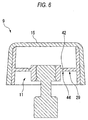
- Fig. 6 shows a second modification, in which a cut-away portion 42 is formed in the crashable connecting portion.
- the cut-away portion 42 in the present embodiment, is formed as a groove and can be formed at the time when the inner knob 11 is formed of resin.
- the cut-away portion 42 is formed in the end portion of a bridge portion 44.
- the cut-away portion 42 is formed in one of the surfaces of the bridge portion 44 that faces the front plate portion 15 of the outer knob 9 and, therefore, the cut-away portion 42 has a depth in the direction of the rotation axis 7.
- Such formation of the cut-away portion 42 eliminates the bent portion of the crashable connecting portion.
- the cut-away portion 42 thanks to provision of the cut-away portion 42, the crashing-direction strength of the bridge portion is lowered, which makes it possible to properly set the impact force to be generated when the crash occurs.
- the cut-away portion is not limited to the groove but a slit may also be used.
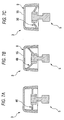
- Figs. 7A to 7C are typical views of a still further modification.
- a crashable connecting portion 46 so as to extend perpendicularly to the rotation axis.
- a crashable connecting portion 48 is disposed so as to be inclined to the rotation axis.
- the crashable connecting portion 48 is disposed in such a manner that it approaches the front plate portion 15 of the outer knob 9 as it goes outwardly.
- a crashable connecting portion 50 is disposed so as to be inclined to the rotation axis.
- the crashable connecting portion 50 is disposed in such a manner that it parts away from the front plate portion 15 of the outer knob 9 as it goes outwardly. In this manner, the crashable connecting portion may also be formed inclined with respect to the rotation axis.
- the bridge portion may be longer; and, the number of bridge portions may not be four but the number may be larger or smaller, or may be two.
- the two or more bridge portions may not be disposed at regular intervals.
- the embodiment shown in Fig. 1 and the modifications shown in Figs. 5A to 7C may also be combined together. What is necessary is to structure the crashable connecting portion in such a manner that it can be crashed with a proper impact force in order to be able to meet the requirements for the collision occupant safety within the scope of the invention.
- the invention is not limited to a volume knob or the operation tool of a car audio; and, the operation tool may be formed so as to be unrotatable, for example, it may be a button. In this manner, the invention can be applied to an arbitrary operation tool of an electronic equipment.
- the operation portion and mounting portion of the operation tool are connected together by the crashable connecting portion, even in case where the mounting portion is positively mounted on the support member, the denting operation of the operation tool can be carried out properly due to the crash of the crashable connecting portion in a collision, so that, while securing the crashing function, the mounting function can be enhanced. Therefore, it is possible to provide an electronic equipment having an effect that the two functions can be properly compatible.
Landscapes
- Rotary Switch, Piano Key Switch, And Lever Switch (AREA)
- Vibration Dampers (AREA)
- Fittings On The Vehicle Exterior For Carrying Loads, And Devices For Holding Or Mounting Articles (AREA)
- Mechanical Control Devices (AREA)
Abstract
Description
- The invention relates to an electronic equipment such as a car audio and, in particular, to an electronic equipment including an operation tool structured such that it can be crashed against an impact.
- In order to enhance the safety of an occupant in a vehicle collision, there is a requirement for safety in an apparatus such as an audio to be incorporated into an instrument panel within a vehicle room. For example, in Europe, assuming that an occupant can collide with an operation tool such as a knob in a vehicle collision, there is established a standard that the operation tool such as a knob must be dented when a certain impact load is applied thereto. In order to be able to meet such standard, conventionally, the operation tool is structured such that it can be crashed against an impact to thereby reduce the degree of the projection of the operation tool from the front surface of the electronic equipment in which the operation tool is incorporated (For example, the patent reference 1: JP-A-2001-266704 (
Page 3, Figs. 1, 2)). - Here, Figs. 8A and 8B show an example of an operation tool in a related art. An
operation tool 100 is a volume knob of a car audio and is supported by anencoder 102 which is used to detect the angle of the knob. Fig. 8A shows theoperation tool 100 in its normal state and Fig. 8B shows theoperation tool 100 when it is crashed. - The
operation tool 100 is composed of anouter knob 104 and aninner knob 106 which are both made of resin. Theouter knob 104 has a cylindrical shape, while it can be picked up and rotated by an operator. Theinner knob 106 is fitted with the inside of theouter knob 104. And, theinner knob 106 includes amounting portion 108 to be mounted on theencoder 102. - The
mounting portion 108 has atube portion 110 which can be fitted with the outside of theencoder 102. Thetube portion 110 has anengaging projection 112 for prevention of removal, while theengaging projection 112 can be engaged with theencoder 102. - Also, the
tube portion 110 includes, on its inner surface, twocrashable projections crashable projections stepped end faces encoder 102, while they can be contacted with these end faces 116, 118. - As shown in Fig. 8B, when the body of the occupant collides with the
operation tool 100 in a vehicle collision, an impact force acts in the arrow mark (in Fig. 8B) direction and, due to the impact force, thecrashable projections mounting portion 108 toward theencoder 102. Accordingly, theoperation tool 100 is allowed to move toward theencoder 102 and thus theoperation tool 100 is dented, thereby satisfying the requirement for the collision safety of the occupant. - However, in the case of the
conventional operation tool 100 shown in Fig. 8, since the twocrashable projections mounting portion 108 and thus there are provided the mounting function and the crashing function in the same portion, there is a possibility that the two functions are not easy to coexist with each other. The crashing function means a function by which, in a collision, the operation tool can be crashed and the projection of the operation tool can be thereby reduced as required. On the other hand, the mounting function means a function by which the operation tool can be supported positively, that is, the shaking motion of the operation tool can be controlled within the required range. - Here, describing the above problem further with reference to Figs. 8A and 8B further, in a vehicle collision, the
crashable projections mounting portion 108 to thereby remove the mounting of themounting portion 108 with respect to theencoder 102, so that themounting portion 108 moves toward theencoder 102 and the whole of theoperation tool 100 also moves toward theencoder 102. That is, to secure the crashing function, removal of the mounting of themounting portion 108 due to the crash of thecrashable projections mounting portion 108. Accordingly, there is a limit on the reinforcement of themounting portion 108 from the viewpoint of prevention of the shaking motion of the operation tool. - Also, according to the structure shown in Figs. 8A and 8B, when the
mounting portion 108 advances toward theencoder 102, thetube portion 110 advances while spreading in a trumpet manner. In case where thetube portion 110 does not cause such trumpet-like spreading deformation, thetube portion 110 will be butted against theencoder 102. Therefore, to secure the crashing function, thetube portion 110 must be weak to such a degree that the above-mentioned spreading deformation is possible. Specifically, the thickness of thetube portion 110 is limited. Therefore, there is a limit on the enhancement in the rigidity of thetube portion 110 from the viewpoint of prevention of the shaking motion. - In this manner, in the conventional structure, the mounting and crashing portions are formed integral with each other, whereas the requirements for the mounting and crashing functions do not agree with each other. And, there exists a trade-off relationship that, in case where one of the two functions is enhanced, the other function is degraded. This means that, in some cases, the two functions are difficult to be compatible. Also, in case where much importance is attached to the crashing function for enhancement in the occupant safety, it is difficult to enhance the mounting function, so that it is sometimes not easy to.reduce the shaking feeling of the operation tool.
- The present invention aims at eliminating the drawbacks found in the above-mentioned electronic equipment of the related art. Accordingly, it is an object of the invention to provide an electronic equipment which not only can secure the sufficient crashing function of the operation tool but also can enhance the mounting function thereof.
- In attaining the above object, according to the invention, there is provided an electronic equipment including an operation tool to be mounted on a support member, wherein the operation tool has an operation portion to be operated by an operator; a mounting portion formed spaced apart from the operation portion in a direction where an impact is applied to the operation tool, the mounting portion being arranged to be mounted on the support member; and a crashable connecting portion for connecting together the operation portion and the mounting portion and also for allowing the operation portion to move with respect to the mounting portion by that said crashable connecting portion is crashed due to an impact given to the operation portion.
- According to this structure, since there is disposed the crashable connecting portion, the portion..of the operation tool for fulfilling the crashing function is separated from the mounting portion thereof. When an impact is given to the operation tool, due to the crash of the crashable connecting portion, the operation portion is allowed to move with respect to the mounting portion, thereby allowing the operation portion to be dented. Even in case where the mounting portion is positively mounted on the support member, the above-mentioned denting operation can be carried out properly. Thanks to this, while securing the crashing function, the mounting function can be enhanced.
- Also, in an electronic equipment according to the invention, the crashable connecting portion is formed so as to extend radially from the mounting portion mounted on a shaft and is connected to the operation portion.
- According to this structure, the crashable connecting portion can be structured such that it is strong in a direction perpendicular to the shaft and is weak in the axial direction, that is, in the crashing direction. The radially extending crashable connecting portion may be perpendicular or oblique to the shaft.
- Also, according to the invention, the crashable connecting portion includes two or more bridge portions which are formed radially in a clearance existing between the mounting portion and operation portion so as to connect together these two portions.
- In this structure, since there are formed the two or more bridge portions in the crashable connecting portion, the crashable connecting portion can be structured such that it is properly weak in the axial direction, that is, in the crashing direction.
- According to the invention, each of the bridge portions has a section shape the thickness of which in a direction along the shaft is smaller than the width thereof in a direction perpendicular to the shaft.
- In this structure, since the section shape of the bridge portion is set in the above-mentioned manner, the crashing-direction strength of the bridge portion is lowered, thereby being able to properly set the impact force that is generated when the crash occurs.
- According to the invention, the crashable connecting portion has a bent portion between the mounting portion and operation portion. Alternatively, the bent portion may also be formed in the bridge portion.
- In this structure as well, since the bent portion is formed, the crashing-direction strength of the bridge portion is lowered, thereby being able to properly set the impact force that is generated when the crash occurs.
- According to the invention, the crashable connecting portion has a cut-away portion between the mounting portion and operation portion.
- In this structure as well, since the cut-away portion is formed, the crashing-direction strength of the bridge portion is lowered, thereby being able to properly set the impact force that is generated when the crash occurs. By the way, a typical example of the cut-away portion is a groove. For example, in case where the operation tool is made of resin, the groove may be formed when the operation tool is molded of resin. Also, the cut-away portion may be composed of a slit.
- Also, an electronic equipment according to the invention comprises an outside piece including an outer tube portion constituting the operation portion and an inside piece including an inner tube portion to be fitted with the outer tube portion, and the inside piece has a structure that the inner tube portion and mounting portion situated on the inner peripheral side thereof are connected together by the crashable connecting portion.
- According to this structure, when obtaining a structure in which there is secured a clearance allowing the operation portion and mounting portion to move with respect to each other, it is not necessary to use a slide mold or the like, which can facilitate the manufacture of the operation tool.
-
- Fig. 1 is a sectional view of an operation tool in an electronic equipment according to an embodiment of the invention;
- Fig. 2 is a sectional view of an operation tool in an electronic equipment according to the embodiment of the invention;
- Figs. 3A to 3C are external views of an operation tool in an electronic equipment according to the embodiment of the invention;
- Fig. 4 is a perspective view of an electronic equipment according to the embodiment of the invention, showing a state in which an operation tool is mounted thereon;
- Figs. 5A and 5B are sectional views of a modification of an operation tool in an electronic equipment according to the embodiment of the invention;
- Fig. 6 is a sectional view of a second modification of an operation tool in an electronic equipment according to the embodiment of the invention;
- Figs. 7A to 7C are sectional views of a third modification of an operation tool in an electronic equipment according to the embodiment of the invention; and
- Figs. 8A and 8B are sectional views of an operation tool in a conventional electronic equipment.
-
- In the drawings, a
reference numeral 1 refers to an electronic equipment; 3 to an. operation tool; 5 to an encoder; 7 to a rotation axis; 9 to an Outer knob; 11 to an inner knob; 13 to an outside cylindrical portion; 15 to a front plate portion; 17 to an inside cylindrical portion; 19 to a mounting cylindrical portion; 21 to a crashable connecting portion; 23 to a knob mounting shaft; 25 to an engaging projection; 27 to engaging groove; 29 to a ring-shaped plate portion; 31 to a bridge portion; 33 to a clearance; and 35 to a bent portion. - Now, description will be given below of an embodiment of an electronic equipment according to the invention with reference the accompanying drawings.
- Figs. 1 to 3C show an operation tool according to an embodiment of the invention, while Fig. 4 shows an electronic equipment into which the present operation tool is incorporated. As shown in Fig. 4, according to the present embodiment, an
electronic equipment 1 is a car audio, and anoperation tool 3 is a volume knob of the car audio. - Figs. 3A to 3C are external views of the
operation tool 3. Figs. 1 and 2 are respectively sectional views taken along the line A-A and line B-B shown in Figs. 3B and 3C. - As shown in these figures, the
operation tool 3 is supported on anencoder 5 which is a support member for detecting the rotation angle of theoperation tool 3, and can be rotated about therotation axis 7 of theencoder 5. And, theoperation tool 3 has a two-piece structure which is composed of anouter knob 9 made of resin serving as an operation portion and aninner knob 11 serving as a mounting portion. - The
outer knob 9 corresponds to the outside makeup portion of theoperation tool 3 and has a cap-like shape composed of an outsidecylindrical portion 13 and afront plate portion 15. And, thefront plate portion 15 of theouter knob 9 is situated on the front surface of the operation tool and faces an operator. - On the other hand, the
inner knob 11 is composed of an insidecylindrical portion 17, a mountingcylindrical portion 19 and acrashable connecting portion 21 for connecting together the twoportions cylindrical portion 17 has a shape which can be fitted with the inside of the outsidecylindrical portion 13 of theouter knob 9 and, as shown in the above figures, the outsidecylindrical portion 13 and insidecylindrical portion 17 are set substantially equal to each other in the rotation-axis-direction length thereof. The insidecylindrical portion 17 is pressure inserted into the outsidecylindrical portion 13, whereby theinner knob 11 and outer knob 8 can be fixed to each other. - The mounting
cylindrical portion 19 is situated inside the insidecylindrical portion 17, the mountingcylindrical portion 19 and insidecylindrical portion 17 are concentric with each other, and the centers of these two cylindrical portions are coincident with therotation axis 7. The mountingcylindrical portion 19 has a shape that can be fitted with the outside of aknob mounting shaft 23 corresponding to therotation shaft 7. - The mounting
cylindrical portion 19 is mounted on theknob mounting shaft 23 by a rotation preventive structure in such a manner that it cannot be rotated with respect to theknob mounting shaft 23. Due to such unrotatable mounting of the mountingcylindrical portion 19, according to the present embodiment, part of the cylinder of theknob mounting shaft 23 is scraped to thereby provide a flat portion (not shown). In the inner peripheral surface of the mountingcylindrical portion 19 as well, there is provided a flat portion having a complementary shape and, in case where these two flat portions are engaged with each other, the rotation of the mountingcylindrical portion 19 with respect to theknob mounting shaft 23 can be prevented. - Further, the mounting
cylindrical portion 19 is also prevented from moving in a direction along therotation axis 7 with respect to theknob mounting shaft 23. That can be realized by a flat portion which can be formed by scraping theknob mounting shaft 23. That is, in the end portion of this flat portion, there is formed a step and, in this step portion, the mountingcylindrical portion 19 andknob mounting shaft 23 are contacted with each other in a direction along therotation axis 7, thereby being able to prevent the mountingcylindrical portion 19 from moving in a direction along therotation axis 7. - Also, the inside diameter of the mounting
cylindrical portion 19 is slightly smaller than the outside diameter of theknob mounting shaft 23 of theencoder 5 and, therefore, theknob mounting shaft 23 can be pressure inserted into the mountingcylindrical portion 19. And, as shown in the above figures, the mountingcylindrical portion 19 has an engagingprojection 25 projecting from the inner peripheral surface thereof and the engagingprojection 25 is engaged with the engaginggroove 27 of theknob mounting shaft 23 of theencoder 5, thereby being able to prevent theoperation tool 3 against removal. Further, the thickness of the mountingcylindrical portion 19 is set so as to be able to obtain sufficient rigidity. According to the present embodiment, since there is not necessary the trumpet-shaped spreading deformation of the mountingcylindrical portion 19 when it is crashed, the thickness of the mountingcylindrical portion 19 can be set large. Thanks to the above structure, the mountingcylindrical portion 19 can be mounted onto the encoder so strongly that theoperation tool 3 can be prevented from shaking. - Next, description will be given below of the structure of the
crashable connecting portion 21. As shown in Fig. 1 and Fig. 3C, thecrashable connecting portion 21 connects the insidecylindrical portion 17 of theinner knob 11 with the mountingcylindrical portion 19 situated on the inner peripheral side of theinner knob 11, while thecrashable connecting portion 21 is composed of a ring-shapedplate portion 29 and abridge portion 31. The ring-shapedplate portion 29 is projected from the inner peripheral surface of the insidecylindrical portion 17 toward the center of theinner knob 11 and extends at right angles to therotation axis 7. - The ring-shaped
plate portion 29 does not reach the mountingcylindrical portion 19 but there is aclearance 33 between the ring-shapedplate portion 29 and mountingcylindrical portion 19. Thebridge portion 31 is disposed in thisclearance 33, and thebridge portion 31 connects together the ring-shapedplate portion 29 and mountingcylindrical portion 19. Thebridge portion 31, as shown in the above figures, has a shape like a relatively short rod. And, there are disposed fourbridge portions 31 at regular intervals along the circumferential direction of theinner knob 11. - Also, the
crashable connecting portion 21 has abent portion 35 in the end portion of thebridge portion 31. In more detail, as shown in Fig. 1, thebridge portion 31 and ring-shapedplate portion 29 are disposed in such a manner that they are shifted from each other in the direction of therotation axis 7 and, specifically, thebridge portion 31 is situated nearer to thefront plate portion 15 of theouter knob 9 than the ring-shapedplate portion 29. Therefore, thecrashable connecting portion 21 is structured such that, when it is viewed from the outside toward the inside, in the terminal end of the ring-shapedplate portion 29, that is, in the start end of thebridge portion 31, it is bent toward thefront plate portion 15, is then bent again toward therotation axis 7, and leads to the mountingcylindrical portion 19. - Also, in the above-mentioned structure, the mounting
cylindrical portion 19 of theinner knob 11, as shown in Figs. 1 and 2, has substantially the same length as theknob mounting shaft 23 of theencoder 5 in the direction of therotation axis 7 and, therefore, the end faces of the mountingcylindrical portion 19 andknob mounting shaft 23 are substantially coincident with each other. And, as shown in Figs. 1 and 2, between the end face of the mountingcylindrical portion 19 and thefront plate portion 15 of theouter knob 9, there is formed a clearance S. - While the structure of the
operation tool 3 according to the.. present embodiment has been.described heretofore, thepresent operation tool 3 can be manufactured in the following manner. Firstly, theouter knob 9 andinner knob 11 are formed using molds respectively. The respective parts can be easily manufactured even in case where a slide mold is not used. - Next, the
inner knob 11 is assembled to theouter knob 9 to thereby provide theoperation tool 3. At the then time, the insidecylindrical portion 17 of theinner knob 11 is pressure inserted into the outsidecylindrical portion 13 of theouter knob 9. Further, theoperation tool 3 is pressed against theknob mounting shaft 23 of theencoder 5 to thereby pressure insert theknob mounting shaft 23 of theencoder 5 into the mountingcylindrical portion 19. At the then time, the engagingprojection 25 of the mountingcylindrical portion 19 is engaged into the engaginggroove 27 of theknob mounting shaft 23. In this manner, theoperation tool 3 is supported on theencoder 5. - Next, description will be given below of the operation of the
operation tool 3 when a vehicle collision occurs. It is assumed now that a vehicle collision occurs and an occupant collides heavily with theoperation tool 3. An impact force given to theoperation tool 3 acts in a direction along therotation axis 7. Due to the impact force, thebridge portion 31 of thecrashable connecting portion 21 is broken and torn off. That is, thebridge portion 31 that is. the weakest in thecrashable connecting portion 21, especially, the bent portion or inner-peripheral-side end portion is crashed. - When the
bridge portion 31 is crashed, the portions of the operation tool that are situated on the outside of thebridge portion 31, that is, theouter knob 9 and the like move toward theencoder 5. As shown in Fig. 1, between thefront plate portion 15 of theouter knob 9 and the end face of the mountingcylindrical portion 19, there is present the clearance S. Until this clearance S disappears, that is, until thefront plate portion 15 is contacted with the mountingcylindrical portion 19, theouter knob 9 and the like move toward theencoder 5. The clearance S corresponds to a variation in the projection quantity of theoperation tool 3 caused by the crash and thus it can be referred to as a crash margin. The movement of theouter knob 9 causes theoperation tool 3 to become dented, thereby being able to satisfy the requirements for enhancement in the safety of the occupant. - In the above operation of the
operation tool 3 in a vehicle collision, thecrashable connecting portion 21 is crashed but the mountingcylindrical portion 19 has no connection with the crashing operation. Therefore, even in case where the mountingcylindrical portion 19 is strongly mounted on theknob mounting shaft 23 of theencoder 5, the above-mentioned crash-connected operation can be carried out positively. - While the
operation tool 3 according to the present embodiment has been described heretofore, in the present embodiment, theencoder 5 corresponds to the support member for supporting theoperation tool 3, theouter knob 9 corresponds to the operation portion of theoperation tool 3, and the mountingcylindrical portion 19 of theinner knob 11 corresponds to the mounting portion to be mounted onto the support member. According to the present embodiment, the mounting portion is disposed in such a manner that it is spaced apart from the operation portion by the clearance S in a direction where the impact acts on the operation tool. And, the crashable connecting portion is crashed due to the impact to thereby move the operation portion with respect to the mounting portion. - As described above, in the present embodiment, there is disposed the above crashable connecting portion and, therefore, the portion of the operation tool that bears the crashing function is separated from the mounting portion. When the impact acts on the operation tool, due to the crash of the crashable connecting portion, the operation portion is moved with respect to the mounting portion, thereby allowing the operation portion to be dented. Even in case where the mounting portion is mounted on the support member positively, the above-mentioned denting operation can be executed properly. Thanks to this, while securing the crashing function, the mounting function can be enhanced.
- Now, let us compare the present embodiment with the conventional structure. In the conventional structure, as has been described with reference to Fig. 8, the crashing function is formed integrally with the mounting portion. That is, the crash structure is disposed in the portion to be mounted onto the support member. In this case, when a crash occurs, the mounting of the operation tool is removed. To secure the crashing function, there is required a mounting removal function for the impact acting time and, therefore, the reinforcement, of the mounting portion is limited.
- On the other hand, in the case of the present embodiment, the mounting portion and crashing function are separated from each other. A crash occurs in the connecting portion between the mounting portion and operation portion but no crash occurs in the portion for mounting the mounting portion onto the support member. And, due to the relative movement between the operation portion and mounting portion caused by the crashed connecting portion, that is, due to the internal crash and deformation of the operation tool, the denting operation of the operation tool can be realized. This can eliminate the need to remove the mounting of the mounting portion on the support member through the crash of the mounting portion as in the conventional structure.. That is, since the removal. of the mounting of the mounting operation is not necessary, even in case where the mounting portion is strong, a crashing function can be secured. Therefore, the crashing function and mounting function are easy to be compatible.
- Also, in the conventional structure, as shown in Fig. 8, to dent the operation tool, the mounting portion must be spread and deformed in a trumpet manner. According to the present embodiment, however, since the mounting portion need not move, it need not be spread and deformed either. From this viewpoint as well, the mounting portion can be reinforced.
- Also, as described above, in the present embodiment, the crashable connecting portion is extended radially from the mounting portion mounted on the shaft and is connected to the operation portion. Due to the radial structure of the crashable connecting portion, the crashable connecting portion can be structured such that it is strong in a direction perpendicular to the shaft, that is, in the present embodiment, it is strong in the rotation direction and in the radial direction and, at the same time, it is weak in the axial direction, that is, in the crashing direction.
- Also, according to the present embodiment, the crashable connecting portion includes two or more bridge portions formed radially in a clearance existing between the.mounting portion and operation.portion so as to connect together these two portions. In the example shown in Figs. 3A to 3C, the number of bridge portions is four. Thanks to provision of the bridge portions, the crashable connecting portion can be structured such that it is properly weak in the axial direction thereof, that is, in the crashing direction thereof.
- Also, according to the present embodiment, the crashable connecting portion includes the bent portions between the mounting portion and operation portion. In more detail, according to the present embodiment, as shown in Fig. 1, in the end portions of the crashable connecting portion that are present outside the bridge portions thereof, that is, in the connecting portions between the bridge portions and ring-shaped plate portion, the crashable connecting portion is bent. Such bent structure can reduce the crashing-direction strength of the bridge portions to thereby be able to properly set the impact force to be provided when a crash occurs.
- Also, as described above, according to the present embodiment, the operation tool is composed of the outer knob serving as the outside piece and inner knob serving as the inside piece. The inner tube portion of the inner piece is fitted with the outer tube portion of the outer piece, while the present inner tube portion and the mounting portion situated on the inner peripheral side of the inner tube portion are connected by the crashable connecting portion. Thanks to this structure, when obtaining a structure having a clearance to allow the operation portion and mounting portion to move with respect to each other, there can be eliminated the need for use of a slide mold or the like, which can facilitate the manufacture of the operation tool.
- Next, description will be given below of modifications of the above-mentioned embodiment.
- Figs. 5A and 5B show a first modification, in which the section shape of the bridge portion is changed. That is, in the embodiment shown in Fig. 1, the section shape of the
bridge portion 31 is substantially square; however, in the modification shown in Fig. 5A, the section shape of abridge portion 40 is rectangular. Thus, as shown in Fig. 5A and 5B, the axial-direction thickness of thebridge portion 40 is set smaller than the width thereof in a direction perpendicular to the shaft (in the present embodiment, the width in the rotation direction). Due to this structure, the crashing-direction strength of the operation tool can be lowered, thereby being able to properly set the impact force to be generated when the crash occurs. - Fig. 6 shows a second modification, in which a cut-away
portion 42 is formed in the crashable connecting portion. The cut-awayportion 42, in the present embodiment, is formed as a groove and can be formed at the time when theinner knob 11 is formed of resin. The cut-awayportion 42 is formed in the end portion of abridge portion 44. The cut-awayportion 42 is formed in one of the surfaces of thebridge portion 44 that faces thefront plate portion 15 of theouter knob 9 and, therefore, the cut-awayportion 42 has a depth in the direction of therotation axis 7. Such formation of the cut-awayportion 42 eliminates the bent portion of the crashable connecting portion. - According to this structure, thanks to provision of the cut-away
portion 42, the crashing-direction strength of the bridge portion is lowered, which makes it possible to properly set the impact force to be generated when the crash occurs. By the way, without departing from the scope of the invention, the cut-away portion is not limited to the groove but a slit may also be used. - Figs. 7A to 7C are typical views of a still further modification. In Fig. 7A, similarly to the embodiment shown in Fig. 1, there is provided a
crashable connecting portion 46 so as to extend perpendicularly to the rotation axis. On the other hand, in Fig. 7B, acrashable connecting portion 48 is disposed so as to be inclined to the rotation axis. Thecrashable connecting portion 48 is disposed in such a manner that it approaches thefront plate portion 15 of theouter knob 9 as it goes outwardly. Also, in Fig. 7C as well, acrashable connecting portion 50 is disposed so as to be inclined to the rotation axis. However, in Fig. 7C, thecrashable connecting portion 50 is disposed in such a manner that it parts away from thefront plate portion 15 of theouter knob 9 as it goes outwardly. In this manner, the crashable connecting portion may also be formed inclined with respect to the rotation axis. - The invention is not limited to the above-mentioned embodiment. For example, the bridge portion may be longer; and, the number of bridge portions may not be four but the number may be larger or smaller, or may be two. The two or more bridge portions may not be disposed at regular intervals. Also, it is also possible to employ a structure in which no bridge portion is included. Also, the embodiment shown in Fig. 1 and the modifications shown in Figs. 5A to 7C may also be combined together. What is necessary is to structure the crashable connecting portion in such a manner that it can be crashed with a proper impact force in order to be able to meet the requirements for the collision occupant safety within the scope of the invention.
- Further, it goes without saying that the above-mentioned embodiment can be deformed properly by a person skilled in the art within the scope of the invention. For example, the invention is not limited to a volume knob or the operation tool of a car audio; and, the operation tool may be formed so as to be unrotatable, for example, it may be a button. In this manner, the invention can be applied to an arbitrary operation tool of an electronic equipment.
- As has been described heretofore, according to the invention, since there is employed a structure in which the operation portion and mounting portion of the operation tool are connected together by the crashable connecting portion, even in case where the mounting portion is positively mounted on the support member, the denting operation of the operation tool can be carried out properly due to the crash of the crashable connecting portion in a collision, so that, while securing the crashing function, the mounting function can be enhanced. Therefore, it is possible to provide an electronic equipment having an effect that the two functions can be properly compatible.
Claims (7)
- An electronic equipment comprising:wherein said operation tool includes:an operation tool to be mounted on a support member;an operation portion to be operated by an operator;a mounting portion formed spaced apart from the operation portion in a direction where an impact is applied to the operation tool, the mounting portion being arranged to be mounted on the support member; anda crashable connecting portion for connecting together the operation portion and the mounting portion and allowing the operation portion to move with respect to the mounting portion by that said crashable connecting portion is crashed due to an impact given to the operation portion.
- The electronic equipment according to Claim 1,
wherein said crashable connecting portion is disposed so as to extend radially from the mounting portion mounted on a shaft and is connected to the operation portion. - The electronic equipment according to Claim 2,
wherein said crashable connecting portion includes plural bridge portions disposed radially in a clearance existing between the mounting portion and the operation portion so as to connect together said mounting portion and said operation portion. - The electronic equipment according to Claim 3,
wherein each of the bridge portions has a section shape the thickness of which in a direction along the. shaft is smaller than the width thereof in a direction perpendicular to the shaft. - The electronic equipment as set forth in Claim 2,
wherein the crashable connecting portion has a bent portion between the mounting portion and the operation portion. - The electronic equipment according to Claim 2,
wherein the crashable connecting portion has a cut-away portion between the mounting portion and the operation portion. - The electronic equipment according to Claim 1, further comprising:wherein the inside piece has a structure in which the inner tube portion and the mounting portion on the inner peripheral side thereof are connected together by the crashable connecting portion.an outside piece including an outer tube portion constituting the operation portion; andan inside piece including an inner tube portion to be fitted with the outer tube portion;
Applications Claiming Priority (2)
| Application Number | Priority Date | Filing Date | Title |
|---|---|---|---|
| JP2003133928 | 2003-05-13 | ||
| JP2003133928A JP4313608B2 (en) | 2003-05-13 | 2003-05-13 | Electronics |
Publications (2)
| Publication Number | Publication Date |
|---|---|
| EP1477876A1 true EP1477876A1 (en) | 2004-11-17 |
| EP1477876B1 EP1477876B1 (en) | 2006-09-06 |
Family
ID=33028331
Family Applications (1)
| Application Number | Title | Priority Date | Filing Date |
|---|---|---|---|
| EP04002162A Expired - Lifetime EP1477876B1 (en) | 2003-05-13 | 2004-01-30 | Electronic equipment |
Country Status (4)
| Country | Link |
|---|---|
| US (1) | US7251861B2 (en) |
| EP (1) | EP1477876B1 (en) |
| JP (1) | JP4313608B2 (en) |
| DE (1) | DE602004002232T2 (en) |
Cited By (1)
| Publication number | Priority date | Publication date | Assignee | Title |
|---|---|---|---|---|
| EP2040274A4 (en) * | 2006-07-12 | 2011-01-12 | Sumitomo Wiring Systems | Switch for vehicle |
Families Citing this family (23)
| Publication number | Priority date | Publication date | Assignee | Title |
|---|---|---|---|---|
| JP4313608B2 (en) * | 2003-05-13 | 2009-08-12 | パナソニック株式会社 | Electronics |
| JP2006066288A (en) * | 2004-08-27 | 2006-03-09 | Mitsubishi Electric Corp | Operating mechanism |
| DE102005003538A1 (en) * | 2005-01-26 | 2006-08-03 | Liberty Hardware Mfg. Corp. | Knob for furniture has grasp head and grasp base, which are separated components centered to each other enclose grasp interior whereby grasp base has center hole, through which fastening screw extends |
| US7479607B2 (en) * | 2006-07-28 | 2009-01-20 | Bose Corporation | Control knob with safety feature |
| JP4325699B2 (en) * | 2007-04-26 | 2009-09-02 | 株式会社デンソー | Operation knob |
| USD582210S1 (en) * | 2007-09-12 | 2008-12-09 | Wolfdale Engineering Limited | Barbeque control |
| JP5233501B2 (en) * | 2007-12-18 | 2013-07-10 | パナソニック株式会社 | Rotating operation type electronic component and electronic device equipped with the same |
| JP5367399B2 (en) * | 2009-02-10 | 2013-12-11 | カルソニックカンセイ株式会社 | In-vehicle dial type operation device |
| JP6130261B2 (en) * | 2012-08-06 | 2017-05-17 | 株式会社東海理化電機製作所 | Shift device |
| US9268356B2 (en) * | 2013-03-15 | 2016-02-23 | Touchsensor Technologies, Llc | Modular knob system |
| JP6187206B2 (en) * | 2013-12-03 | 2017-08-30 | 株式会社デンソー | Operating device |
| CN106158450B (en) * | 2015-04-22 | 2019-01-29 | 比亚迪股份有限公司 | Vehicle mounted multimedia revolves press-key structure and vehicle |
| USD781126S1 (en) * | 2016-02-10 | 2017-03-14 | Wolf Appliance, Inc. | Cooktop control knob with a reflective ring |
| USD849478S1 (en) | 2016-02-10 | 2019-05-28 | Wolf Appliance, Inc. | Gas cooktop with vertically mounted control knob panel |
| US10401035B2 (en) | 2016-02-10 | 2019-09-03 | Wolf Appliance, Inc. | Vertically mounted gas cooktop control knob |
| USD806512S1 (en) * | 2016-12-22 | 2018-01-02 | Whirlpool Corporation | Knob |
| USD824237S1 (en) * | 2016-12-28 | 2018-07-31 | Whirlpool Corporation | Knob |
| USD848239S1 (en) * | 2017-10-06 | 2019-05-14 | Harman International Industries, Incorporated | Control knob |
| USD924660S1 (en) | 2020-05-12 | 2021-07-13 | Sub-Zero Group, Inc. | Control knob with a digital display |
| USD1024724S1 (en) | 2020-06-02 | 2024-04-30 | Sub-Zero Group, Inc. | Control knob |
| DE102020128465B3 (en) | 2020-10-29 | 2022-03-24 | Dr. Ing. H.C. F. Porsche Aktiengesellschaft | Mounting device for mounting a display device in the interior of a vehicle |
| US11608987B1 (en) | 2021-01-12 | 2023-03-21 | Sub-Zero Group, Inc. | Control knob with display |
| US11255535B1 (en) | 2021-01-12 | 2022-02-22 | Sub-Zero Group, Inc. | Illuminated control knob |
Citations (4)
| Publication number | Priority date | Publication date | Assignee | Title |
|---|---|---|---|---|
| DE1278860B (en) * | 1966-10-18 | 1968-09-26 | Philips Patentverwaltung | Connection between the control button and the drive shaft or axle of an adjustment device, preferably for motor vehicles |
| US3513720A (en) * | 1968-07-26 | 1970-05-26 | Amerace Corp | Breakaway handle |
| DE2941626A1 (en) * | 1979-10-13 | 1981-04-23 | Fa. Leopold Kostal, 5880 Lüdenscheid | Collapsible knob for vehicle instrument panels - has partitioned inverted pyramid sides which fold together into knob top |
| US6512189B1 (en) * | 1999-11-22 | 2003-01-28 | Preh-Werke Gmbh & Co. Kg | Rotary switch |
Family Cites Families (13)
| Publication number | Priority date | Publication date | Assignee | Title |
|---|---|---|---|---|
| US2797592A (en) * | 1952-09-03 | 1957-07-02 | Patent Button Company Of Tenne | Appliance knobs |
| JPS5552499Y2 (en) * | 1976-10-18 | 1980-12-05 | ||
| GB2046192B (en) * | 1979-03-27 | 1983-03-16 | Kigass Eng Ltd | Handle assemblies |
| US5469758A (en) * | 1993-11-03 | 1995-11-28 | The Grigoleit Company | Knob with soft plastic cover |
| US5509174A (en) * | 1994-12-06 | 1996-04-23 | K I Industries, Inc. | Appliance knob and bezel assembly |
| US5752759A (en) * | 1997-03-07 | 1998-05-19 | Illinois Tool Works Inc. | Illuminated knob assembly |
| US6242064B1 (en) * | 1997-06-11 | 2001-06-05 | The Grigoleit Company | Method of attaching a cover to a tubular body such as a knob or a button and a knob or button of said method |
| JP3542288B2 (en) | 1998-10-07 | 2004-07-14 | 森六株式会社 | Instrument panel support structure for automobiles |
| JP2001039250A (en) | 1999-07-30 | 2001-02-13 | Kanto Auto Works Ltd | Interior equipment fitting structure for automobile |
| JP2001266704A (en) | 2000-03-22 | 2001-09-28 | Matsushita Electric Ind Co Ltd | Knob apparatus |
| US6499191B1 (en) * | 2000-06-29 | 2002-12-31 | The Grigoleit Company | Knob with a composite light pipe having a colored face and a light pipe |
| US6826805B2 (en) * | 2002-03-01 | 2004-12-07 | Illinois Tool Works Inc. | Collapsible control knob |
| JP4313608B2 (en) * | 2003-05-13 | 2009-08-12 | パナソニック株式会社 | Electronics |
-
2003
- 2003-05-13 JP JP2003133928A patent/JP4313608B2/en not_active Expired - Fee Related
-
2004
- 2004-01-29 US US10/767,983 patent/US7251861B2/en not_active Expired - Lifetime
- 2004-01-30 DE DE602004002232T patent/DE602004002232T2/en not_active Expired - Lifetime
- 2004-01-30 EP EP04002162A patent/EP1477876B1/en not_active Expired - Lifetime
Patent Citations (4)
| Publication number | Priority date | Publication date | Assignee | Title |
|---|---|---|---|---|
| DE1278860B (en) * | 1966-10-18 | 1968-09-26 | Philips Patentverwaltung | Connection between the control button and the drive shaft or axle of an adjustment device, preferably for motor vehicles |
| US3513720A (en) * | 1968-07-26 | 1970-05-26 | Amerace Corp | Breakaway handle |
| DE2941626A1 (en) * | 1979-10-13 | 1981-04-23 | Fa. Leopold Kostal, 5880 Lüdenscheid | Collapsible knob for vehicle instrument panels - has partitioned inverted pyramid sides which fold together into knob top |
| US6512189B1 (en) * | 1999-11-22 | 2003-01-28 | Preh-Werke Gmbh & Co. Kg | Rotary switch |
Cited By (1)
| Publication number | Priority date | Publication date | Assignee | Title |
|---|---|---|---|---|
| EP2040274A4 (en) * | 2006-07-12 | 2011-01-12 | Sumitomo Wiring Systems | Switch for vehicle |
Also Published As
| Publication number | Publication date |
|---|---|
| US7251861B2 (en) | 2007-08-07 |
| DE602004002232T2 (en) | 2007-09-06 |
| JP2004338427A (en) | 2004-12-02 |
| DE602004002232D1 (en) | 2006-10-19 |
| JP4313608B2 (en) | 2009-08-12 |
| US20040226142A1 (en) | 2004-11-18 |
| EP1477876B1 (en) | 2006-09-06 |
Similar Documents
| Publication | Publication Date | Title |
|---|---|---|
| US7251861B2 (en) | Electronic equipment | |
| JP4485281B2 (en) | Fastener | |
| EP0796780A2 (en) | Interlocking device for opposed racks in an adjustable steering column | |
| JPH08133102A (en) | Stroke end shock absorber for steering mechanism | |
| EP3535750B1 (en) | Ultrasonic transducer | |
| CN104773116A (en) | Clip and pillar garnish mounting structure | |
| JP2002064313A (en) | Automotive rod antenna device | |
| US5951194A (en) | Attachment element for a body in a wall | |
| JP5873408B2 (en) | Airbag module mounting structure | |
| JP2008041654A (en) | Switch for vehicle | |
| EP0818378A2 (en) | Shroud for a vehicle steering column | |
| CN101490775B (en) | vehicle switch | |
| US20060283285A1 (en) | Operation mechanism | |
| JP2005193899A (en) | Device for attaching structural element to steering column jacket | |
| JP4719983B2 (en) | Steering wheel with airbag device | |
| KR101172101B1 (en) | Telescope Steering Apparatus | |
| JP2006210288A (en) | Projection amount displacement structure, knob structure and projection amount displacement method | |
| JP4184519B2 (en) | Device for fixing a rectangular parallelepiped electronic recording device releasably | |
| JPH11283706A (en) | Connector mounting structure | |
| JP2006052806A (en) | Cushion clip | |
| KR100471876B1 (en) | steering shaft rotation preventing device | |
| JPH06298101A (en) | Steering column cover | |
| JP3891742B2 (en) | Parking brake operation device | |
| JP3758137B2 (en) | Bound stopper | |
| JP2008296813A (en) | Shift lever device for vehicle |
Legal Events
| Date | Code | Title | Description |
|---|---|---|---|
| PUAI | Public reference made under article 153(3) epc to a published international application that has entered the european phase |
Free format text: ORIGINAL CODE: 0009012 |
|
| AK | Designated contracting states |
Kind code of ref document: A1 Designated state(s): AT BE BG CH CY CZ DE DK EE ES FI FR GB GR HU IE IT LI LU MC NL PT RO SE SI SK TR |
|
| AX | Request for extension of the european patent |
Extension state: AL LT LV MK |
|
| 17P | Request for examination filed |
Effective date: 20050309 |
|
| AKX | Designation fees paid |
Designated state(s): DE FR IT |
|
| GRAP | Despatch of communication of intention to grant a patent |
Free format text: ORIGINAL CODE: EPIDOSNIGR1 |
|
| RBV | Designated contracting states (corrected) |
Designated state(s): DE FR GB IT |
|
| RBV | Designated contracting states (corrected) |
Designated state(s): DE FR GB |
|
| GRAS | Grant fee paid |
Free format text: ORIGINAL CODE: EPIDOSNIGR3 |
|
| GRAA | (expected) grant |
Free format text: ORIGINAL CODE: 0009210 |
|
| AK | Designated contracting states |
Kind code of ref document: B1 Designated state(s): DE FR GB |
|
| REG | Reference to a national code |
Ref country code: GB Ref legal event code: FG4D |
|
| REF | Corresponds to: |
Ref document number: 602004002232 Country of ref document: DE Date of ref document: 20061019 Kind code of ref document: P |
|
| ET | Fr: translation filed | ||
| PLBE | No opposition filed within time limit |
Free format text: ORIGINAL CODE: 0009261 |
|
| STAA | Information on the status of an ep patent application or granted ep patent |
Free format text: STATUS: NO OPPOSITION FILED WITHIN TIME LIMIT |
|
| 26N | No opposition filed |
Effective date: 20070607 |
|
| REG | Reference to a national code |
Ref country code: GB Ref legal event code: 746 Effective date: 20091221 |
|
| REG | Reference to a national code |
Ref country code: GB Ref legal event code: S117 Free format text: REQUEST FILED; REQUEST FOR CORRECTION UNDER SECTION 117 FILED ON 2 DECEMBER 2009 |
|
| REG | Reference to a national code |
Ref country code: FR Ref legal event code: PLFP Year of fee payment: 13 |
|
| REG | Reference to a national code |
Ref country code: FR Ref legal event code: PLFP Year of fee payment: 14 |
|
| REG | Reference to a national code |
Ref country code: FR Ref legal event code: PLFP Year of fee payment: 15 |
|
| PGFP | Annual fee paid to national office [announced via postgrant information from national office to epo] |
Ref country code: FR Payment date: 20181213 Year of fee payment: 16 |
|
| PGFP | Annual fee paid to national office [announced via postgrant information from national office to epo] |
Ref country code: GB Payment date: 20190130 Year of fee payment: 16 Ref country code: DE Payment date: 20190115 Year of fee payment: 16 |
|
| REG | Reference to a national code |
Ref country code: DE Ref legal event code: R119 Ref document number: 602004002232 Country of ref document: DE |
|
| GBPC | Gb: european patent ceased through non-payment of renewal fee |
Effective date: 20200130 |
|
| PG25 | Lapsed in a contracting state [announced via postgrant information from national office to epo] |
Ref country code: FR Free format text: LAPSE BECAUSE OF NON-PAYMENT OF DUE FEES Effective date: 20200131 Ref country code: GB Free format text: LAPSE BECAUSE OF NON-PAYMENT OF DUE FEES Effective date: 20200130 Ref country code: DE Free format text: LAPSE BECAUSE OF NON-PAYMENT OF DUE FEES Effective date: 20200801 |