BACKGROUND OF THE INVENTION
FIELD OF THE INVENTION
The present invention relates generally to machinery, and more particularly, to
improvement of a damping mechanism of the machinery.
PRIOR ART
Precision instruments such as coordinate measuring machine are provided with
movable bodies. Although these types of precision instruments require high speed and high
precision, vibrations more easily occur with increases in speed and precision. Precision
instruments in particular require improvements in relation to performance irregularities. In
the precision instruments, there are the performance irregularities arising from the vibrations
occurred by the instruments. If these vibrations can be suppressed, the speed and precision
of the precision instruments can be further increased.
In the prior art, in order to increase the speed and precision of precision instruments,
damping vibrations by using elastic rubber or springs had been considered.
Also in the prior art, although there is technology that negates the reaction force
during stage movement, using this to increase the speed and precision of precision
instruments can also be considered (for example, Japanese Patent Application Laid-Open
Publication Nos. 2002-170765, 2002-175963, 2001-230178, 2001-118773, 2000-243811 and
2000-216082). This prior art technology, for example, provides a mass that is equivalent to
that of the stage. This prior art technology, by linearly moving the mass in the direction
opposite to the direction of movement of the stage using reactive force during movement of
the stage, negates the reaction force during stage movement.
However, even if the elastic rubber, etc., or the prior art methods described in the
aforementioned patent documents are used to increase the speed and precision of precision
instruments, a satisfactory damping effect cannot be attained.
In seeking to further increase the speed and precision of precision instruments, there
is a limit to the increase the speed and precision because more vibrations are occurred. In
precision instruments, although there is still room for improvement in performance
irregularities due to vibrations, there has been no suitable technology that can solve this
problem in the prior art.
SUMMARY OF THE INVENTION
The present invention was conceived in light of the above problem of the prior art,
and the object thereof is to provide a machinery that can improve performance irregularities
arising from vibrations.
The machinery of the present invention to achieve the above object is a machinery
having a movable body, comprising an active damper. The active damper comprises a sensor,
an actuator and a controller.
In this case, the movable body moves linearly with respect to the main body.
The active damper controls an inherent vibration of the movable body occurred in a
direction of movement of the movable body.
The sensor is provided with the movable body. The sensor detects the inherent
vibration currently occurred in the direction of movement of the movable body, among one or
a plurality of the inherent vibrations of the movable body.
The actuator is provided with the movable body. The actuator generates a vibration
in the direction of movement of the movable body.
The controller allows the actuator to generate the vibration having a negative phase
relationship with respect to the inherent vibration detected by the sensor.
For the inherent vibration of the movable body of the present invention, the inherent
vibration possessed by the movable body with respect to a reference point within the movable
body, already attained in a state where the movable body is not being moved, is cited as an
example.
The negative phase vibration referred to herein is, with regard to phase, the vibration
that has a negative phase with respect to the phase of the inherent vibration of the movable
body. With regard to frequency, it has the same frequency as that of the inherent vibration
possessed by the movable body. With regard to amplitude, it has a sign that is the opposite
to that of the amplitude of the inherent vibration possessed by the movable body, and a size
(absolute value) that is the same as that of the amplitude of the inherent vibration of the
movable body.
Inherent vibrations of the movable body referred to herein include those that have an
inherent single (resonance) frequency, or a plurality of different (resonance) frequencies.
Measurement precision, repetition precision, and movement precision are cited as
examples of the performance of the machinery of the present invention.
In the present invention, the active damper is continuously operated. The sensor
continuously detects the inherent vibration of the movable body currently occurred in the
direction of movement of the movable body. The actuator continuously generates the
vibration in the direction of movement of the movable body. The controller preferably
allows the actuator to continuously generate the vibration having the negative phase
relationship with respect to the inherent vibration detected by the sensor.
In the present invention, the movable body is provided with at least the sensor and
the actuator of the active damper. In the present invention, the machinery further comprises
a memory. The controller acquires, from the memory, a control information to the actuator
that is optimum for damping the inherent vibration detected by the sensor. The controller
preferably allows the actuator to generate the vibration based on the acquired control
information.
In this case, the memory stores a relationship between information, acquired
beforehand in a state where the movable body is not being moved, relating to one or a
plurality of the inherent vibrations of the movable body, and a control information to the
actuator that is optimum for generating the vibration having the negative phase relationship
with respect to the inherent vibration of the movable body.
In the present invention, the machinery preferably comprises an adapter.
In this case, the adapter is removably provided with the movable body. The adapter
holds at least the sensor and the actuator of the active damper.
In the present invention, the actuator comprises a pair of flywheels and a motor.
The controller preferably allows the motor to perform the speed of rotation control of the
flywheels so that the flywheels generate the vibration in the negative phase relationship with
respect to the inherent vibration detected by the sensor.
In this case, the flywheels are rotatable in opposite directions at an equivalent speed,
for generating the vibration having the negative phase relationship with respect to the inherent
vibration detected by the sensor in the direction of movement of the movable body.
The motor rotates the flywheels at the speed of rotation determined based on a
frequency of the inherent vibration detected by the sensor.
In the present invention, the movable body is a probe of a coordinate measuring
machine. At least the sensor and the actuator of the active damper are provided with the
probe of the coordinate measuring machine.
As used herein, providing the sensor and the actuator in the probe of a coordinate
measuring machine includes providing the sensor and the actuator directly in the probe, and
providing the sensor and the actuator on a spindle for attachment to the probe.
The coordinate measuring machine of the present invention is called a
three-dimensional coordinate measuring machine. The three-dimensional coordinate
measuring machine is provided with mutually perpendicular guides, and a scale and the probe
that obtain the movement amount of the guides. The coordinate measuring machine can
thereby obtain three-dimensional coordinate values for the probe based on the obtained
movement amount.
The probe of the coordinate measuring machine of the present invention is a detector
for detecting the three-dimensional coordinates of points on an object to be measured. Types
of probes available are contact type and non-contact type probes.
BRIEF DESCRIPTION OF THE DRAWINGS
The above and other objects, aspects, features and advantages of the present
invention will become more apparent from the following detailed description when taken in
conjunction with the accompanying drawings, in which:
DESCRIPTION OF THE PREFERRED EMBODIMENT
The preferred embodiment of the present invention will be described hereunder with
reference to the drawings.
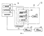
Fig. 1 shows a schematic structure of a machinery according to an embodiment of the
present invention.
In the present embodiment, as a movable body that is to be damped, a Z axis spindle
that moves in an X axis direction in a state where it is provided with a probe of a coordinate
measuring machine will be assumed. An example wherein damping of the inherent vibration
in the X axis direction of the probe is performed will be explained.
The coordinate measuring machine (machinery) 10 shown in the drawing is provided
with coordinate measuring machine main body (main body) 12, a Z axis spindle (movable
body) 14, and an active damper 16.
Here, the Z axis spindle 14 moves linearly in an X axis direction (direction of
movement) with respect to the coordinate measuring machine main body 12.
The active damper 16 is provided with a sensor 18, an actuator 20, and a controller
22. The sensor 18 and the actuator 20 are provided at the tip portion of the Z axis spindle
14.
The active damper 16 controls inherent vibrations possessed by the Z axis spindle 14
that occur in the X axis direction, which is the direction of movement, of the Z axis spindle
14.
The sensor 18 includes a vibration acceleration sensor or the like. The sensor 18 is
provided at the tip portion of the Z axis spindle 14 to which a probe (omitted from the
drawing) is attached. The sensor 18 continuously detects, among single or plural inherent
vibrations possessed by the Z axis spindle 14, an inherent vibration component (vibration
frequency, phase, amplitude, etc.) currently occurring in the X axis direction of the Z axis
spindle 14. Signals from the sensor 18 are sequentially input to the controller 22.
The actuator 20 is provided with the Z axis spindle 14. The actuator 20
continuously generates a vibration in the X axis direction of the Z axis spindle 14, thereby
continuously vibrating the Z axis spindle 14.
The controller 22 is provided with a memory 26 and a CPU 28. The CPU 28
comprises a vibration component acquirer 30, a control information acquirer 32 and an
indicator 34. The controller 22 controls the movement of the actuator 20 via a drive circuit
24. That is, the controller 22 continuously generates, with respect to the actuator 20, a
vibration having a negative phase relationship with respect to the inherent vibration currently
generated in the Z axis spindle 14, acquired by the sensor 18.
Here, the memory 26 stores a relationship between one or a plurality of inherent
vibrations of the Z axis spindle 14, and control information for the actuator 20 suitable for
generating a vibration having a negative phase relationship with respect to the inherent
vibration of the tip portion of the Z axis spindle 14, already acquired in a state where the Z
axis spindle 14 is not being moved.
In the present embodiment, a vibration is generated by the actuator 20 in a state
where the Z axis spindle 14 is not being moved. While changing the frequency of the
vibration generated by the actuator 20, the vibration amplitude thereof is monitored by the
sensor 18. The controller 22, when the peak of the vibration amplitude monitored by the
sensor 18 exceeds a threshold, stores the frequency at that time in the memory 26 as the
inherent frequency of the Z axis spindle 14.
The vibration component acquirer 30 continuously acquires components (frequency,
amplitude and/or phase) of the inherent vibration currently occurred in the Z axis spindle 14
based on a signal from the sensor 18.
The control information acquirer 32 acquires from the memory 26 control
information for the actuator 20 suitable for damping of the inherent vibration currently
occurred in the Z axis spindle 14, acquired from the sensor 18.
The indicator 34 continuously generates a vibration with respect to the actuator 20
according to control information acquired from the control information acquirer 32.
In the present embodiment, a CMM controller 36 and data processor 38 are provided.
The CMM controller 36 comprises, for example, a computer. The CMM controller
36 performs numerical control, by means of the computer, of movement along each axis of
the coordinate measuring machine main body 12, and measurement operations.
The data processor 38 obtains necessary dimensions such as hole diameters, hole
positions and level differences of the object being measured, based on X, Y and Z coordinates
obtained by the measurement operations of the coordinate measuring machine main body 12.
The coordinate measuring machine 10 according to the present embodiment is
constructed roughly as above, and its operation will be explained below.
In the present embodiment, having as its object to improve irregularities in the
measuring precision of the coordinate measuring machine 10, an active damper 16 is provided
at the tip of the Z axis spindle 14. Also, in the present embodiment, a vibration having a
negative phase relationship with respect to the inherent vibration of the coordinate measuring
machine main body 12 is applied to the tip portion of the Z axis spindle 12. Because in the
present embodiment the inherent vibration of the coordinate measuring machine main body
12 can thereby be greatly reduced, increasing the precision of the coordinate measuring
machine 10 can be reliably achieved.
That is, a probe is provided with the tip portion of the Z axis spindle 14 of the
coordinate measuring machine main body 12. The measuring element of the probe tip
acquires X, Y and Z coordinates in the instant that it is in contact with the object being
measured, whereby measurement of coordinates is performed.
In this type of coordinate measuring machine 10, residual vibration after high speed
movement of the Z axis spindle 14 and vibration during low speed movement when
measuring in particular become problems.
In other words, when attempting high speed positioning of the probe in proximity to
measurement sites on the object being measured, an acceleration G is applied when
accelerating at the commencement of high speed positioning. Further, a deceleration G is
applied to the probe when decelerating. These kinds of external forces are the causes of
vibration of the Z axis tip portion at times of high speed movement.
Thereafter, when the measuring element of the probe is placed in contact with the
object being measured at low speed, X, Y and Z coordinates are read at the time of contact,
and relative movement of the probe is immediately stopped. When measuring by this kind
of fine movement, minute vibrations occur, therefore irregular errors often occur in the
measured values.
Thus, in the present embodiment, the sensor 18 and the actuator 20 are provided at
the tip portion of the Z axis spindle 14. In the present embodiment, by imparting a vibration
having a negative phase relationship to the minute vibration occurring at the tip portion of the
Z axis spindle 14 at least when commencing deceleration and during low speed movement of
the Z axis spindle 14, it is preferable to perform active control with respect to the Z axis
spindle 14.
In other words, the controller 22, in order to suppress residual vibration after high
speed movement of the Z axis spindle 14, performs active control of the Z axis spindle 14
when decelerating after high speed movement.
Also, after positioning, because the Z axis spindle 14 approaches the object being
measured at measuring speed, there is a possibility that some vibration will remain at this time.
In order to remove low speed vibration that may occur in the Z axis spindle 14 when
measuring, the controller 22 performs active control of the Z axis spindle 14 even when it
moves at measuring speed.
By thus performing active control of the Z axis spindle 14, the inherent vibration
currently occurred in the tip portion of the Z axis spindle 14 and the vibration applied to the
actuator 20 cancel each other out. The inherent vibration occurred in the Z axis spindle 14 is
thereby, theoretically, zero.
As a result, in the present embodiment, the vibration occurred in the Z axis spindle
14 can be greatly reduced during point measurement when residual vibration after high speed
movement of the Z axis spindle 14 is particularly problematic, and during scanning
measurement when vibration during low speed measurement is particularly problematic.
Consequently, in the present embodiment, because irregularities in the measuring
precision of the coordinate measuring machine 10 occurring due to vibration of the Z axis
spindle 14 can be improved, increasing the precision of the coordinate measuring machine 10
can be achieved.
Continuous Operation
The inventors of the present invention, as a result of examining the timing at which
the active controller is operated, found that although operating the actuator 20 (for example,
immediately performing damping when deceleration of the Z axis spindle 14 commences
and/or during low speed movement) only when oscillation is detected in at least the Z axis
spindle 14 is important, in the present embodiment, continuously operating the active damper
16 is more important. The reason for this is that, in the actuator 20, there are times when it
is difficult to control transient states from a state where damping control is performed (state
where actuator 20 is operating) to a state where damping control is not performed (state where
actuator 20 is not operating).
Thus, what is characteristic about the present embodiment is that the sensor 18 is
continuously operated and vibrations generated by the actuator 20 are continuously controlled.
Also, according to the inventors of the present invention, having confirmed that inherent
vibration is continuously generated in the Z axis spindle 14, it is particularly preferable for the
active damper 16 to be continuously operated.
As a result, in the present embodiment, the sensor 18 continuously detects inherent
vibrations currently generated in the X axis direction of the Z axis spindle 14 of the
coordinate measuring machine 10.
The actuator 20 continuously generates vibrations in the X axis direction.
The controller 22 continuously generates in the actuator 20 a vibration having a
negative phase relationship to the inherent vibration currently occurred in the Z axis spindle
14 and detected by the sensor 18 from moment to moment.
As a result, in the present embodiment, compared to a case where the actuator 20 is
operated only when vibration is detected, active damping by the actuator 20 with respect to
the Z axis spindle 14 can be more reliably and easily performed.
Oscillation
The inventors of the present invention, as a result of conducting examinations of a
more preferred active damper, found that correctly distinguishing whether changes in the
signal waveform from the sensor 18 are due to acceleration G/deceleration G of the Z axis
spindle 14, or due to oscillation, is important. Also, they understood that it is particularly
preferable to perform this distinction before controlling damping. By doing this, in the
present embodiment, more favorable active damping can be performed based on the signal
from the sensor 18.
Hereunder, an example where active damping is performed based on oscillation of
the signal from the sensor 18 will be explained in detail.
That is, if the rigidity of the Z axis spindle 14 is extremely high and vibrations do not
often occur in the Z axis spindle 14, the sensor 18 outputs only the acceleration G or
deceleration G. However, because this is not oscillation, it is preferable that the new
damping control instruction by the controller 22 to the actuator 20 be performed after
detection of oscillation.
For this reason the controller 22 continuously monitors the existence of changes in
the signal waveform from the sensor 18. In the present embodiment, when there is a change
in the signal waveform from the sensor 18, it determines whether that change is due to
vibration or acceleration.
In the present embodiment, the controller 22 determines whether changes in the
signal waveform from the sensor 18 are due to oscillation based on whether a vibration
frequency corresponding to the frequency of the inherent vibration of the Z axis spindle 14 is
stored in the memory 26.
In other words, the controller 22, if there is vibration frequency information within
the memory 26 corresponding to the signal waveform of the signal from the sensor 18,
determines that in this case the change in signal is due to oscillation. On the other hand, if
there is no vibration frequency information within the memory 26 corresponding to the signal
waveform of the signal from the sensor 18, the controller 22 determines that in this case the
change in signal is not due to oscillation.
Then, if oscillation is not detected with respect to the signal waveform from the
sensor 18, the controller 22 continues using the control information from immediately before
as is, without changing the control information to the actuator 20. On the other hand, if an
oscillation different to that immediately before is detected with respect to the signal waveform
from the sensor 18, the controller 22 acquires from the memory 26 the optimum control
information for damping the inherent vibration that differs to that from immediately before.
Then, the controller 22 generates a vibration in the actuator 20 based on the newly acquired
control information.
In this way the controller 22, based on the signal waveform from the sensor 18,
continuously monitors changes in the inherent vibration of the Z axis spindle 14 currently
being occurred. Then, if it detects a different oscillation, the controller 22 immediately
performs optimum operation control of the actuator 20 according to that inherent vibration.
Thereby, in the present embodiment, compared to a machinery that has no device for
determining oscillation, active damping of the Z axis spindle 14 is performed more reliably.
Adapter
The inventors of the present invention, as a result of examining how to mount the
active damper on the coordinate measuring machine main body, found that adapting at least
the sensor and the actuator is particularly preferable. As a result, in the present embodiment,
the flexibility with which the active damper is provided to the coordinate measuring machine
main body has been improved.
Hereunder, adaptation of the sensor and the actuator will be described in detail.
Fig. 2 shows a preferred example of mounting the active damper according to the
present embodiment on the coordinate measuring machine main body 12.
In the drawing, in the active damper, the sensor and the actuator are detachably
provided at the tip portion of the Z axis spindle 14 in a state where they are held within an
adapter 40.
In the present embodiment, the upper portion of the adapter 40 is detachably formed
in the lower portion of the Z axis spindle 14. The lower portion of the adapter 40 is
detachably formed in a probe adapter 44.
In this way, the adapter 40 that holds the active damper is freely detachable with
respect to the Z axis spindle 14. Thereby, the active damper 16 of the present embodiment is
easily attached not only to an exclusive coordinate measuring machine, but to existing
coordinate measuring machines.
As a result, compared to a fixed type active damper 16, in the present embodiment
flexibility with respect to existing coordinate measuring machines has been improved.
Irregularities in measurement precision can thereby be improved in more coordinate
measuring machines.
[Coordinate Measuring Machine Main Body]
The coordinate measuring machine main body 12 is provided with a main body base
46, a measuring table 48, and a column 50 fixed to the main body base 46.
The measuring table 48 is provided so as to be movable in the Y direction with
respect to the man body base 46. The measuring table 48 moves the object being measured
in the Y direction.
The Z axis spindle 14 is provided so as to be movable in the X and/or Z directions
with respect to the column 50. The Z axis spindle 14 moves the probe 42 in the X and/or Z
directions.
Here, in the present embodiment, the probe 42 moves in the X direction and the
inherent vibration of the probe 42 is occurred in the X direction. Therefore in the present
embodiment the inherent vibration in the X direction is damped.
Because the inherent vibration of the probe 42 occurs in the X direction in this way,
the actuator is vibrated in the X direction.
In the present embodiment, in order to at least remove residual vibration after high
speed movement of the Z axis spindle 14 (during high speed movement in the X direction of
the probe 42), active control is performed when decelerating after high speed movement.
Also, in the present embodiment, in order to at least remove low speed vibration
during low speed measurement by the Z axis spindle 14 (during low speed movement in the X
direction of the probe 42), active damping is performed when moving at measuring speed.
Actuator
The inventors of the present invention, as a result of conducting investigations
regarding the actuator, found that using a flywheel is particularly preferred.
Alternatively, in the present embodiment, a pneumatic or hydraulic direct drive
cylinder can also be used.
However, using a rotating body such as a flywheel as the actuator is excellent from
the viewpoint of ease of design and manufacture, therefore this is more preferable.
Also, compared to a direct drive body as the actuator, a rotating body that can use the
rotation of a motor as is can be easily designed and manufactured. In addition, although
using a direct drive body driven by a linear motor as the actuator can also be considered,
because a linear guide is necessary the structure becomes complicated and damping becomes
difficult.
Thus, in the present embodiment, using a flywheel in particular as the actuator is
preferable.
As a result, controlling vibrations in a single direction can be performed with high
efficiency and a simple structure, therefore design and manufacture are easy.
In Fig. 3, an active damper using a flywheel that is preferably used in the present
embodiment is shown.
The adapter 40 shown in the drawing is provided with a base frame 51, an actuator
20 and a sensor 18. In the base frame 51 are held the actuator 20 and the sensor 18.
The sensor 18 detects oscillation with respect to the base frame (a reference point)
51.
The actuator 20 is provided with a motor 52 having its axis of rotation in the Z
direction, a pair of gears 54 and 56 having axes of rotation in the Z direction, and a pair of
flywheels 58 and 60 having their axes of rotation in the Z direction.
In this actuator 20, the gear 54 and flywheel 58 are provided on the axis of rotation
of the motor 52.
The rotation of the motor 52 is transferred to the flywheel 58 and to the flywheel 60
via the gears 54 and 56.
Consequently, the flywheels 58 and 60 rotatably operate in opposite directions at the
same speed. The flywheels 58 and 60 can thereby generate in the X direction a vibration
having a negative phase relationship to the inherent vibration (the inherent vibration currently
occurred in the Z axis spindle) obtained by the sensor 18.
Here, the controller controls the rotation of the flywheels 58 and 60 by means of the
motor 52 so that the flywheels 58 and 60 rotate at a frequency determined based on the
frequency of the inherent vibration (the frequency of the inherent vibration of the Z axis
spindle currently being occurred) detected by the sensor 18.
Limit of the Direction of Vibration
Because the coordinate measuring machine according to the present embodiment
employs a table movement type, the Z axis spindle 14 occurs vibration in mainly the X axis
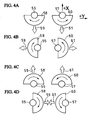
direction. Consequently, in the present embodiment, the arrangement of the flywheels 58
and 60 is as shown in Figs. 4A to 4D. Vibration of the actuator 20 can thereby be aligned to
the X axis direction which is the direction of the vibration of the Z axis spindle.
In other words, the flywheels 58 and 60 are pivoted in the same eccentric state, and
rotatably operate in opposite directions around rotation shafts 55 and 57. Here, when the
flywheels 58 and 60 are in attitude 1 as shown in Fig. 4A, moments 59 and 61 are generated
in the negative direction to the X direction. For this reason double moment in the direction
negative to the X direction is generated in the actuator.
On the other hand, when the flywheels 58 and 60 are in attitude 2 as shown in Fig.
4B, moments 59 and 61 cancel each other out in the Y direction. As a result moment is zero
in Fig. 4B.
Then, when the flywheels 58 and 60 are in attitude 3 as shown in Fig. 4C, moments
59 and 61 are generated in the positive direction to the X direction. For this reason, in Fig.
4C, double moment in the direction positive to the X direction is generated in the actuator.
On the other hand, when the flywheels 58 and 60 are in attitude 4 as shown in Fig.
4D, moments 59 and 61 cancel each other out in the Y direction. As a result moment is zero
in Fig. 4D.
By rotating the flywheels 58 and 60, moment is cyclically generated in the positive
and negative direction of the X direction, and vibration is thereby generated in the actuator.
As a result, in the present embodiment, by employing the arrangement of flywheels 58 and 60
shown in the drawings, the actuator can only generate vibrations in the positive and negative
directions of the X direction.
Therefore, in the present embodiment, using the vibration in only the positive and
negative directions of the X direction of the actuator thus obtained, the following damping is
performed.
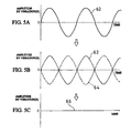
That is, when the inherent vibration signal 62 as shown in Fig. 5A is detected by the
sensor, a vibration signal 64 having a negative phase relationship to the inherent vibration
signal 62 as shown in Fig. 5B is generated in the actuator.
Then, the peak part of one vibration component is positioned at the trough part of the
other vibration component. As a result of this, the inherent vibration currently being
occurred and the vibration of the actuator cancel each other out.
As a result, the vibration currently occurred in the Z axis spindle theoretically has an
amplitude of zero as shown in Fig. 5C and disappears.
[Synchronization]
The controller, in order to perform the aforementioned active damping control, must
synchronize the inherent vibration signal 62 from the sensor and the angular speed of the
motor. The controller can thereby generate in the actuator a signal 64 of a vibration having a
negative phase relationship with respect to the signal 62 of the inherent vibration from the
sensor, as shown in Fig. 5B.
[Speed of Rotation]
The vibration occurred at the tip portion of the Z axis spindle is inherent to that
structure. Therefore in the present embodiment, a vibration that may occur in the tip portion
of the Z axis spindle is detected beforehand by the sensor. Then, the frequency components
and size of the vibration that may occur in the tip portion of the Z axis spindle are calculated.
In the present embodiment, it is preferable to select the size of the flywheels to match the size
of the detected vibration.
The frequencies of the flywheels are preferably adjusted by the rotational speed of
the motor. That is, by adjusting the speed of rotation of the motor based on the inherent
vibration frequency at which the Z axis spindle vibrates, the rotational speed of the flywheels
can be adjusted. Therefore in the present embodiment the mass and amount of imbalance of
the flywheels can be decided based on the moment of inertia in the speed of rotation.
[Shapes of the Flywheels]
In the present embodiment, any type of shape can be used as the flywheel shape.
However, semicircular shapes are preferred as the shapes of the flywheels in the present
embodiment from the viewpoint that they are excellent in terms of ease of processing.
[Continuous Operation]
In particular when flywheels are used, it is difficult to control transient states from a
state where damping control is performed (state where the flywheels are rotating) to the state
where damping control is not performed (state where the flywheels are not rotating).
Therefore, in particular in an actuator using flywheels, operating the sensor
continuously and controlling the rotation of the flywheels continuously is more preferable.
According to the coordinate measuring machine of the present embodiment
described above, at least the sensor and the actuator of the active damper are provided with
the Z axis spindle tip portion. Then, a vibration having a negative phase relationship to the
inherent vibration possessed by the coordinate measuring machine is applied to the Z axis
spindle tip portion.
As a result, the inherent vibrations of machines can be greatly reduced.
Consequently, because irregularities in the measuring precision of coordinate measuring
machines which may occur due to vibration can be improved, increased precision of
coordinate measuring machines can be achieved.
Furthermore, in the present embodiment, by merely attaching the active damper,
irregularities in the measuring precision of coordinate measuring machines can be improved
without increasing the rigidity of the structure. Thereby, the performance of coordinate
measuring machine can be improved at low cost.
Incidentally, the present invention is not limited to the above structure, and various
modifications are possible within the scope of the gist of the invention.
For example, in the above structure, an example was explained wherein an active
damper was provided with respect to a coordinate measuring machine. However, the present
invention is not limited to this and can be applied to anything if it is a machinery that is
provided with a movable body. The present invention can also be favorably applied to
variety of machinery from coordinate measuring machines to, for example, coordinate
measuring machines, machining tools, general processing machines, and positioning devices.
Also, in the present embodiment, an example using control by means of rotating
flywheels as the actuator was explained. However, the actuator of the present embodiment is
not limited to this structure, and any structure that can perform damping with respect to a
weight having a predetermined mass by imparting a vibration having a negative phase
relationship with the inherent vibration of a movable body is permissible. At this time, the
weight is one to which a vibration is applied by a piezoelectric element, a pneumatic or
hydraulic piston or an electromagnetic drive source such as voice coil.
Further, an example in which the inherent vibration of the movable body occurs in
only one axial direction and the vibration for damping it was also generated in the same
direction was explained. However, the present invention is not limited to this, and the
vibration direction can be two axial directions (vibration within a plane) or three axial
directions (solid vibration). In other words, in the present invention, a negative phase
vibration having a negative phase, the same amplitude and the same cycle with respect to the
inherent vibration is generated in the actuator so that the inherent vibration having the
vibration direction, amplitude and cycle detected by the sensor is canceled.
According to the machinery of the present invention as explained above, an active
damper is provided for controlling an inherent vibration possessed by a movable body
currently occurred in the direction of movement of the movable body. As a result, in the
present invention, irregularities in the performance of machinery can be improved.
Also in the present invention, the active damper is continuously operated. Thereby,
irregularities in the performance of machinery can be further improved in the present
invention.
Further, in the present invention, in order to generate a vibration in a negative phase
relationship to the inherent vibration of a movable body detected beforehand, a memory for
storing optimum control information for the actuator is provided. Thereby, in the present
invention improvement of irregularities in the performance of machinery can be more easily
and reliably executed.
Moreover, in the present invention the sensor and the actuator are held in an adapter.
Improvement of irregularities in performance can thereby be carried out in more machinery in
the present invention.
Further still, flywheels are used as actuators in the present invention. Irregularities
in the performance of machinery can thereby be improved more cheaply.
Yet further still, in the present invention the active damper is provided with respect to
a probe of a coordinate measuring machine. Thereby, in the present invention irregularities
in the performance of coordinate measuring machines can be improved.
While illustrative and presently preferred embodiments of the present invention have
been described in detail herein, it is to be understood that the inventive concepts may be
otherwise variously embodied and employed and that the appended claims are intended to be
construed to include such variations except insofar as limited by the prior art.