EP1477760A2 - Compound type heat exchanger - Google Patents
Compound type heat exchanger Download PDFInfo
- Publication number
- EP1477760A2 EP1477760A2 EP04011569A EP04011569A EP1477760A2 EP 1477760 A2 EP1477760 A2 EP 1477760A2 EP 04011569 A EP04011569 A EP 04011569A EP 04011569 A EP04011569 A EP 04011569A EP 1477760 A2 EP1477760 A2 EP 1477760A2
- Authority
- EP
- European Patent Office
- Prior art keywords
- heat exchanging
- passage member
- pseudo
- tubes
- heat
- Prior art date
- Legal status (The legal status is an assumption and is not a legal conclusion. Google has not performed a legal analysis and makes no representation as to the accuracy of the status listed.)
- Withdrawn
Links
- 150000001875 compounds Chemical class 0.000 title claims abstract description 18
- 238000010030 laminating Methods 0.000 claims abstract description 11
- 238000005192 partition Methods 0.000 claims description 19
- 238000005219 brazing Methods 0.000 claims description 7
- 238000005253 cladding Methods 0.000 claims description 6
- 239000000463 material Substances 0.000 claims description 4
- 238000003475 lamination Methods 0.000 abstract 2
- 239000003921 oil Substances 0.000 description 30
- 238000001816 cooling Methods 0.000 description 6
- 230000004048 modification Effects 0.000 description 4
- 238000012986 modification Methods 0.000 description 4
- 238000004378 air conditioning Methods 0.000 description 3
- 230000008030 elimination Effects 0.000 description 3
- 238000003379 elimination reaction Methods 0.000 description 3
- 239000007788 liquid Substances 0.000 description 3
- 230000005540 biological transmission Effects 0.000 description 2
- 229910000838 Al alloy Inorganic materials 0.000 description 1
- 239000010718 automatic transmission oil Substances 0.000 description 1
- 230000015572 biosynthetic process Effects 0.000 description 1
- 239000002826 coolant Substances 0.000 description 1
- 238000010438 heat treatment Methods 0.000 description 1
- 238000009434 installation Methods 0.000 description 1
- 239000010705 motor oil Substances 0.000 description 1
Images




Classifications
-
- F—MECHANICAL ENGINEERING; LIGHTING; HEATING; WEAPONS; BLASTING
- F28—HEAT EXCHANGE IN GENERAL
- F28D—HEAT-EXCHANGE APPARATUS, NOT PROVIDED FOR IN ANOTHER SUBCLASS, IN WHICH THE HEAT-EXCHANGE MEDIA DO NOT COME INTO DIRECT CONTACT
- F28D1/00—Heat-exchange apparatus having stationary conduit assemblies for one heat-exchange medium only, the media being in contact with different sides of the conduit wall, in which the other heat-exchange medium is a large body of fluid, e.g. domestic or motor car radiators
- F28D1/02—Heat-exchange apparatus having stationary conduit assemblies for one heat-exchange medium only, the media being in contact with different sides of the conduit wall, in which the other heat-exchange medium is a large body of fluid, e.g. domestic or motor car radiators with heat-exchange conduits immersed in the body of fluid
- F28D1/04—Heat-exchange apparatus having stationary conduit assemblies for one heat-exchange medium only, the media being in contact with different sides of the conduit wall, in which the other heat-exchange medium is a large body of fluid, e.g. domestic or motor car radiators with heat-exchange conduits immersed in the body of fluid with tubular conduits
- F28D1/0408—Multi-circuit heat exchangers, e.g. integrating different heat exchange sections in the same unit or heat exchangers for more than two fluids
- F28D1/0426—Multi-circuit heat exchangers, e.g. integrating different heat exchange sections in the same unit or heat exchangers for more than two fluids with units having particular arrangement relative to the large body of fluid, e.g. with interleaved units or with adjacent heat exchange units in common air flow or with units extending at an angle to each other or with units arranged around a central element
- F28D1/0443—Combination of units extending one beside or one above the other
-
- F—MECHANICAL ENGINEERING; LIGHTING; HEATING; WEAPONS; BLASTING
- F28—HEAT EXCHANGE IN GENERAL
- F28F—DETAILS OF HEAT-EXCHANGE AND HEAT-TRANSFER APPARATUS, OF GENERAL APPLICATION
- F28F13/00—Arrangements for modifying heat-transfer, e.g. increasing, decreasing
-
- F—MECHANICAL ENGINEERING; LIGHTING; HEATING; WEAPONS; BLASTING
- F28—HEAT EXCHANGE IN GENERAL
- F28F—DETAILS OF HEAT-EXCHANGE AND HEAT-TRANSFER APPARATUS, OF GENERAL APPLICATION
- F28F9/00—Casings; Header boxes; Auxiliary supports for elements; Auxiliary members within casings
- F28F9/02—Header boxes; End plates
- F28F2009/0285—Other particular headers or end plates
- F28F2009/0287—Other particular headers or end plates having passages for different heat exchange media
-
- F—MECHANICAL ENGINEERING; LIGHTING; HEATING; WEAPONS; BLASTING
- F28—HEAT EXCHANGE IN GENERAL
- F28F—DETAILS OF HEAT-EXCHANGE AND HEAT-TRANSFER APPARATUS, OF GENERAL APPLICATION
- F28F2270/00—Thermal insulation; Thermal decoupling
Definitions
- the present invention relates to a compound type heat exchanger having a plurality of independent heat exchanging units, such as condenser and oil cooler, integrated with each other.
- an automobile is equipped with some heat exchanging units, for example, a radiator for cooling an engine, an air conditioning condenser, an oil cooler for cooling automatic transmission oil (i.e. ATF oil cooler), an oil cooler for cooling engine oil and so on.
- a radiator for cooling an engine for example, an air conditioning condenser, an oil cooler for cooling automatic transmission oil (i.e. ATF oil cooler), an oil cooler for cooling engine oil and so on.
- the above radiator and the condenser are individually arranged in the front area of an engine.
- a compound type heat exchanger where a condenser and an oil cooler are integrated in one body has been developed.
- Japanese Patent Application Laid-open No. 2000-18880 discloses a compound type heat exchanger provided, between a condenser and an oil cooler, with a pseudo heat exchanging passage member in which such a heat exchanging medium does not flow.
- a compound type heat exchanger comprising: a core part having a plurality of heat exchanging tubes each formed to allow passage of a heat exchanging medium therein, the heat exchanging tubes being juxtaposed to each other, and a plurality of fins each interposed between the adjoining heat exchanging tubes so that the heat exchanging tubes and the fins are laminated alternately; a pair of header pipes arranged on both ends of the heat exchanging tubes and connected to respective ends of the heat exchanging tubes; a pseudo heat exchanging passage member formed so as not to allow passage of the heat exchanging medium therein and arranged so as to substitute for a specified heat exchanging tube of the heat exchanging tubes and a fin adjoining the specified heat exchanging tube on either left or right side thereof, the pseudo heat exchanging passage member having a substantially L-shaped section; and partition walls each arranged in the header pipes so as to be close to the pseudo heat exchanging passage member thereby to divide spaces inside the header pipes in a direction per
- the pseudo heat exchanging passage member having the substantially L-shaped section since the pseudo heat exchanging passage member having the substantially L-shaped section is arranged in place of the specified heat exchanging tube and the fin adjoining the specified heat exchanging tube, the pseudo heat exchanging passage member comes into line-contact or point-contact with the heat exchanging tube or the fin adjoining the pseudo heat exchanging passage member. Accordingly, the quantity of heat conduction produced between the first heat exchanging unit and the second heat exchanging unit is reduced remarkably, whereby the heat exchanging performance of the heat exchanger as a whole can be maintained highly. Noted, such an elimination of the fin would make the flow of cooling wind passing through the core part smooth thereby reducing the draft resistance too much. Nevertheless, according to the preferred embodiment, the pseudo heat exchanging passage member having the substantially L-shaped section serves to suppress such an excessive reduction of draft resistance.
- the pseudo heat exchanging passage member is provided, on one side thereof in the laminating direction, with projections that abut on the heat exchanging tube adjoining the pseudo heat exchanging passage member.
- a compound type heat exchanger comprising: a core part having a plurality of heat exchanging tubes each formed to allow passage of a heat exchanging medium therein, the heat exchanging tubes being juxtaposed to each other, and a plurality of fins each interposed between the adjoining heat exchanging tubes so that the heat exchanging tubes and the fins are laminated alternately; a pair of header pipes arranged on both ends of the heat exchanging tubes and also connected to respective ends of the heat exchanging tubes; a pseudo heat exchanging passage member formed so as not to allow passage of the heat exchanging medium therein and arranged so as to substitute for a specified heat exchanging tube of the heat exchanging tubes and a fin adjoining the specified heat exchanging tube on either left or right side thereof, the pseudo heat exchanging passage member having a substantially Z-shaped section; and partition walls each arranged in the header pipes so as to be close to the pseudo heat exchanging passage member thereby to divide spaces inside the header pipes in a direction perpendicular to the longitudinal
- the pseudo heat exchanging passage member having the substantially Z-shaped section is arranged in place of the specified heat exchanging tube and the fin adjoining the specified heat exchanging tube, the quantity of heat conduction produced between the first heat exchanging unit and the second heat exchanging unit is reduced remarkably, whereby the heat exchanging performance of the heat exchanger as a whole can be maintained highly.
- such an elimination of the fin would make the flow of cooling wind passing through the core part smooth thereby reducing the draft resistance too much.
- the pseudo heat exchanging passage member having the substantial Z-shaped section serves to suppress such an excessive reduction of draft resistance.
- the pseudo heat exchanging passage member is arranged so that both ends thereof in the laminating direction do not abut on the heat exchanging tubes adjoining the pseudo heat exchanging passage member.
- the pseudo heat exchanging passage member is provided, on one end thereof in the laminating direction, with projections that abut on the heat exchanging tube adjoining the pseudo heat exchanging passage member.
- Each of the heat exchanging tubes may be covered with a cladding layer of brazing material.
- the heat exchanging tube can be joined to the adjoining fins by brazing, improving the strength of the core part.
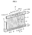
- Fig. 1 is a perspective view of a compound type heat exchanger 10 in accordance with the first embodiment of the present invention.
- the heat exchanger 10 of this embodiment includes an upper header pipe 11 on the upper side, a lower header pipe 12 on the lower side, a core part 13 connecting the upper header pipe 11 with the lower header pipe 12 in the vertical direction and a liquid tank 14 connected to the lateral side of the lower header pipe 12.
- fins are eliminated in order to exhibit the constitution of the heat exchanger 10 clearly.
- a heat exchanger's part on the left side ("L" side shown in Fig.
- a pseudo heat exchanging passage member 15 constitutes an oil cooler unit 16 (as the first heat exchanging unit), while another heat exchanger's part on the right side ("R" side shown in Fig. 1) of the pseudo heat exchanging passage member 15 constitutes a condenser unit 17 (as the second heat exchanging unit).
- the condenser unit 17 serves to cool a cooling medium for air conditioning cycle, while the oil cooler unit 16 cools a transmission oil for an automatic car.
- the upper header pipe 11 has an upper pipe 18 and a lower pipe 19 both of which are adjacent to each other in the vertical direction.
- the upper pipe 18 is communicated with the lower pipe 19 through joint members 20, 21 having a plurality of through-holes 20a, 21a, respectively.
- the upper pipe 18 is closed up by two disk-shaped partition walls 22, 23 positioned in the way of the pipe 18 in the longitudinal direction. These partition walls 22, 23 are apart from each other.
- the lower pipe 19 is provided, therein, with partition walls 24, 25 at respective positions corresponding to the partition walls 22, 23 of the upper pipe 18.
- the lower pipe 19 further includes one partition wall 26 closer to the liquid tank 14.
- the above joint member 20, 21 are disposed between the partition wall 24 and the partition wall 26. Again, the partition walls 22, 23 and the partition walls 24, 25 are arranged apart from each other at predetermined intervals, respectively.
- the lower header pipe 12 is formed by an upper pipe 27 and a lower pipe 28 both of which are adjacent to each other.
- the upper pipe 27 is communicated with the lower pipe 28 through joint members 29, 30 and 31.
- partition walls 32-37 are arranged in the pipes 27, 28, as shown in the figure.
- Juxtaposed in the core part 13 are a plurality of heat exchanging tubes 38 that extend vertically and allow the heat exchanging medium to flow therein.
- Each of corrugated fins (see Fig. 2) is arranged between the adjoining heat exchanging tubes 38. Noted that not only the partition walls 32, 33 but the partition walls 36, 37 are apart from each other at predetermined intervals, respectively.
- Fig. 2 is an enlarged sectional view of a part A of Fig. 1.
- the upper and lower pipes 18, 19 are provided with the partition walls 22-25.
- the pseudo heat exchanging passage member 15 is arranged below the substantial middle points between the opposing partition walls 22 and 23 and also between the opposing partition walls 24 and 25.
- the pseudo heat exchanging passage member 15 has its upper end 15a formed with a width substantially equal to the width of the heat exchanging tube 38, providing a substantial L-shaped section, as shown in Fig. 3.
- the pseudo heat exchanging passage member 15 has a lateral part 15b extending rearward of the vehicle and a front part 15c extending to the right direction of the vehicle, both of which are formed into one body, providing the substantial L-shaped section.
- the front part 15c is arranged so that its leading end 15d abuts on the adjoining heat exchanging tube 38.
- each of the heat exchanging tubes 38 has a hollow interior and its outer surface coated with a cladding layer 39 made of a brazing material, through which the fins 40 are joined to the tube 38.
- a cladding layer 39 made of a brazing material, through which the fins 40 are joined to the tube 38.
- respective peaks 41 of the fins 40 abut on the cladding layer 39 of the brazing material (e.g. aluminum alloys) on the outer surface of the heat exchanging tube 39.
- the brazing material e.g. aluminum alloys
- FIG. 6 the flows of a medium 42 and oil 43 in the heat exchanger 10 of the embodiment will be described.
- the above-mentioned fins 40 are eliminated in order to clarify such flows of the medium 42 and the oil 43.
- the medium 42 flowing into the upper pipe 18 of the upper header pipe 11 passes through the joint members 20, 21 and the-lower pipe 19 and successively flows in the heat exchanging pipes 38 downwardly. Subsequently, the medium 42 flows from the lower header pipe 12 to the liquid tank 14 and thereafter, the medium 42 flows in the heat exchanging pipes 38 upwardly. After that, the medium 42 is returned to an air-conditioning cycle through the lower pipe 19 of the upper header pipe 11.
- the oil 43 entering from the upper pipe 27 of the lower header pipe 12 flows in the heat exchanging tubes 38 upwardly and turns back at the lower pipe 19 of the upper header pipe 11. Subsequently, after flowing in the heat exchanging pipes 38 downwardly, the oil is returned to a transmission through the lower pipe 28 of the lower header pipe 12.
- the temperature of the medium 42 flowing the condenser unit 17 is about 60°C
- the temperature of the oil flowing the oil cooler unit 16 is about 110°C being a remarkable high temperature.
- the heat exchanger 10 of the first embodiment owing to the provision of the pseudo heat exchanging passage member 15 between the oil cooler unit 16 and the condenser unit 17, there is almost no heat conduction from the oil cooler unit 16 of high temperature to the condenser unit 17 of relatively how temperature, whereby the heat exchanging performance of the heat exchanger 10 as a whole can be maintained.
- the conventional heat exchanger there is a possibility of heat conduction from an oil cooler unit of high temperature to a condenser unit through the intermediary of a pseudo heat exchanging passage member because the pseudo heat exchanging passage member is welded to fins on respective sides of the oil cooler unit 16 and the condenser unit 17.
- the pseudo heat exchanging passage member 15 having a substantial L-shaped section serves to suppress such an excessive reduction of draft resistance.
- the second embodiment differs from the first embodiment in the shape of the pseudo heat exchanging passage member.
- a heat exchanger 45 is also provided with a pseudo heat exchanging passage member 44 whose upper end 44a has a width substantially equal to the width of the heat exchanging tube 38, which is similar to the pseudo heat exchanging passage member 15 of the first embodiment.
- the pseudo heat exchanging passage member 44 further includes a lateral part 44b extending rearward of the vehicle and a front part 44c extending to the right direction of the vehicle, both of which are formed into one body, providing the substantial L-shaped section.
- the front part 44c is provided, at a tip thereof, with a plurality of projections 44d which abut on the adjoining heat exchanging tube 38.
- the heat exchanger 45 constructed above, owing to the formation of the projections 44d, it is possible to reduce a contact area of the pseudo heat exchanging passage member 44 with the adjoining heat exchanging tube 38 in comparison with the contact area of the first embodiment, whereby the quantity of heat conduction from the oil cooler unit 16 to the condenser unit 17 can be reduced furthermore.
- the third embodiment differs from the second embodiment in the shape of the pseudo heat exchanging passage member.
- a heat exchanger 46 is also provided with a pseudo heat exchanging passage member 47 whose upper end 47a has a width substantially equal to the width of the heat exchanging tube 38, which is similar to the pseudo heat exchanging passage members 15, 44 of the first and second embodiments. As shown in Figs.
- the pseudo heat exchanging passage member 47 further includes a rear part 47b arranged on the rear side of the vehicle to extend to the right in the vehicle's traveling direction (left in the figure), a body part 47c extending from the left end (right in the figure) of the part 47b to the forward of the vehicle and a front part 47d extending from the front end of the part 47c to the left in the vehicle's traveling direction (right in the figure), all of which are formed into one body, providing a substantial Z-shaped section.
- the right end (left in the figure) of the rear part 47b and the left end (right in the figure) of the front part 47d are arranged apart from the adjoining heat exchanging tubes 38 at intervals, respectively.
- the right end of the rear part 47b and the left end of the front part 47d may be arranged so as to abut on the adjoining heat exchanging tubes 38.
- the heat exchanger 46 constructed above, there are eliminated left and right fins to be arranged on both sides of the boundary between the oil cooler unit 16 and the condenser unit 17 and one heat exchanging tube to be arranged between these left and right fins, while there is provided the pseudo heat exchanging passage member 47 having a substantial Z-shaped section instead of these fins and the heat exchanging tube therebetween. Again, since both left and right ends of the pseudo heat exchanging passage member 47 do not abut on the adjoining heat exchanging tubes 38, 38, the quantity of heat conduction from the oil cooler unit 16 to the condenser unit 17 is reduced furthermore.
- the pseudo heat exchanging passage member 47 may be provided, at the right end of the rear part 47b and the left end of the front end 47d, with projections abutting on the adjoining heat exchanging tubes 38, 38.
Landscapes
- Engineering & Computer Science (AREA)
- Physics & Mathematics (AREA)
- Thermal Sciences (AREA)
- Mechanical Engineering (AREA)
- General Engineering & Computer Science (AREA)
- Details Of Heat-Exchange And Heat-Transfer (AREA)
- Heat-Exchange Devices With Radiators And Conduit Assemblies (AREA)
- Air-Conditioning For Vehicles (AREA)
Abstract
Description
- The present invention relates to a compound type heat exchanger having a plurality of independent heat exchanging units, such as condenser and oil cooler, integrated with each other.
- Normally, an automobile is equipped with some heat exchanging units, for example, a radiator for cooling an engine, an air conditioning condenser, an oil cooler for cooling automatic transmission oil (i.e. ATF oil cooler), an oil cooler for cooling engine oil and so on. Hitherto, the above radiator and the condenser are individually arranged in the front area of an engine. Recently, in view of reducing the installation space of such units for purpose of the downsizing of an engine and also reducing the number of assembling steps of the units, a compound type heat exchanger where a condenser and an oil cooler are integrated in one body has been developed.
- In the compound type heat exchanger, however, there is a great difference in temperature between a heat exchanging medium flowing the condenser and oil flowing the oil cooler. Therefore, Japanese Patent Application Laid-open No. 2000-18880 discloses a compound type heat exchanger provided, between a condenser and an oil cooler, with a pseudo heat exchanging passage member in which such a heat exchanging medium does not flow.
- In the above-mentioned compound type heat exchanger, however, fins are connected to both sides of the pseudo heat exchanging passage member by means of brazing. Therefore, there is a possibility that heat of oil flowing the oil cooler is transmitted to the heat exchanging medium flowing the condenser to deteriorate the heat exchanging efficiency of the heat exchanger.
- In the above-mentioned situation, it is an object of the present invention to provide a compound type heat exchanger having a plurality of heat exchanging units, which can suppress heat conduction from the heat exchanging unit of high temperature to the heat exchanging unit of low temperature.
- In order to attain the above object, according to the first aspect of the invention, there is provided a compound type heat exchanger, comprising: a core part having a plurality of heat exchanging tubes each formed to allow passage of a heat exchanging medium therein, the heat exchanging tubes being juxtaposed to each other, and a plurality of fins each interposed between the adjoining heat exchanging tubes so that the heat exchanging tubes and the fins are laminated alternately; a pair of header pipes arranged on both ends of the heat exchanging tubes and connected to respective ends of the heat exchanging tubes; a pseudo heat exchanging passage member formed so as not to allow passage of the heat exchanging medium therein and arranged so as to substitute for a specified heat exchanging tube of the heat exchanging tubes and a fin adjoining the specified heat exchanging tube on either left or right side thereof, the pseudo heat exchanging passage member having a substantially L-shaped section; and partition walls each arranged in the header pipes so as to be close to the pseudo heat exchanging passage member thereby to divide spaces inside the header pipes in a direction perpendicular to the longitudinal direction of the header pipes, wherein the core part and the header pipes are divided in a direction perpendicular to the laminating direction of the heat exchanging tubes and the fins at a boundary of the pseudo heat exchanging passage member into a first heat exchange unit and a second heat exchange unit.
- With the above-mentioned constitution, since the pseudo heat exchanging passage member having the substantially L-shaped section is arranged in place of the specified heat exchanging tube and the fin adjoining the specified heat exchanging tube, the pseudo heat exchanging passage member comes into line-contact or point-contact with the heat exchanging tube or the fin adjoining the pseudo heat exchanging passage member. Accordingly, the quantity of heat conduction produced between the first heat exchanging unit and the second heat exchanging unit is reduced remarkably, whereby the heat exchanging performance of the heat exchanger as a whole can be maintained highly. Noted, such an elimination of the fin would make the flow of cooling wind passing through the core part smooth thereby reducing the draft resistance too much. Nevertheless, according to the preferred embodiment, the pseudo heat exchanging passage member having the substantially L-shaped section serves to suppress such an excessive reduction of draft resistance.
- In another preferred embodiment, the pseudo heat exchanging passage member is provided, on one side thereof in the laminating direction, with projections that abut on the heat exchanging tube adjoining the pseudo heat exchanging passage member.
- In this case, since the contact area between the pseudo heat exchanging passage member and the heat exchanging tube or the fin is reduced furthermore, it is possible to reduce the quantity of heat conduction between the first heat exchanging unit and the second heat exchanging unit, whereby the heat exchanging performance of the heat exchanger as a whole can be maintained highly.
- According to the second aspect of the invention, there is also provided a compound type heat exchanger, comprising: a core part having a plurality of heat exchanging tubes each formed to allow passage of a heat exchanging medium therein, the heat exchanging tubes being juxtaposed to each other, and a plurality of fins each interposed between the adjoining heat exchanging tubes so that the heat exchanging tubes and the fins are laminated alternately; a pair of header pipes arranged on both ends of the heat exchanging tubes and also connected to respective ends of the heat exchanging tubes; a pseudo heat exchanging passage member formed so as not to allow passage of the heat exchanging medium therein and arranged so as to substitute for a specified heat exchanging tube of the heat exchanging tubes and a fin adjoining the specified heat exchanging tube on either left or right side thereof, the pseudo heat exchanging passage member having a substantially Z-shaped section; and partition walls each arranged in the header pipes so as to be close to the pseudo heat exchanging passage member thereby to divide spaces inside the header pipes in a direction perpendicular to the longitudinal direction of the header pipes, wherein the core part and the header pipes are divided in a direction perpendicular to the laminating direction of the heat exchanging tubes and the fins at a boundary of the pseudo heat exchanging passage member into a first heat exchanging unit and a second heat exchanging unit.
- With the above-mentioned constitution, since the pseudo heat exchanging passage member having the substantially Z-shaped section is arranged in place of the specified heat exchanging tube and the fin adjoining the specified heat exchanging tube, the quantity of heat conduction produced between the first heat exchanging unit and the second heat exchanging unit is reduced remarkably, whereby the heat exchanging performance of the heat exchanger as a whole can be maintained highly. As similar to the first aspect of the invention, such an elimination of the fin would make the flow of cooling wind passing through the core part smooth thereby reducing the draft resistance too much. Nevertheless, according to the present invention, the pseudo heat exchanging passage member having the substantial Z-shaped section serves to suppress such an excessive reduction of draft resistance.
- In a preferred embodiment, the pseudo heat exchanging passage member is arranged so that both ends thereof in the laminating direction do not abut on the heat exchanging tubes adjoining the pseudo heat exchanging passage member.
- In this case, since no contact area is produced between the pseudo heat exchanging passage member and the heat exchanging tubes on both sides of the pseudo heat exchanging passage member, it is possible to reduce the quantity of heat conduction between the first heat exchanging unit and the second heat exchanging unit, whereby the heat exchanging performance of the heat exchanger as a whole can be maintained highly.
- The pseudo heat exchanging passage member is provided, on one end thereof in the laminating direction, with projections that abut on the heat exchanging tube adjoining the pseudo heat exchanging passage member.
- In this configuration, since the contact area between the pseudo heat exchanging passage member and the heat exchanging tube or the fin is reduced furthermore, it is possible to reduce the quantity of heat conduction between the first heat exchanging unit and the second heat exchanging unit, whereby the heat exchanging performance of the heat exchanger as a whole can be maintained highly.
- Each of the heat exchanging tubes may be covered with a cladding layer of brazing material.
- Then, owing to the interposition of the cladding layer between each heat exchanging tube and the adjoining fin, the heat exchanging tube can be joined to the adjoining fins by brazing, improving the strength of the core part.
- These and other objects and features of the present invention will become more fully apparent from the following description and appended claims taken in conjunction with the accompany drawings.
-
- Fig. 1 is a perspective view of a heat exchanger in accordance with the first embodiment of the present invention;
- Fig. 2 is a sectional view of a part A of Fig. 1 in enlargement;
- Fig. 3 is a sectional view taken along a line 3-3 of Fig. 2;
- Fig. 4 is a sectional view of a part C of Fig. 2 in enlargement;
- Fig. 5 is a sectional view of a part D of Fig. 2 in enlargement;
- Fig. 6 is a schematic view showing the flows of medium and oil in the heat exchanger of the first embodiment;
- Fig. 7 is a sectional view showing the substantial part of the heat exchanger in accordance with the second embodiment of the present invention;
- Fig. 8 is a sectional view taken along a line 8-8 of Fig. 7;
- Fig. 9 is a sectional view showing the substantial part of the heat exchanger in accordance with the third embodiment of the present invention; and
- Fig. 10 is a sectional view taken along a line 10-10 of Fig. 9.
-
- Referring to accompanying drawings, an embodiment of the present invention will be described below.
- Fig. 1 is a perspective view of a compound
type heat exchanger 10 in accordance with the first embodiment of the present invention. As shown in this figure, theheat exchanger 10 of this embodiment includes anupper header pipe 11 on the upper side, alower header pipe 12 on the lower side, acore part 13 connecting theupper header pipe 11 with thelower header pipe 12 in the vertical direction and aliquid tank 14 connected to the lateral side of thelower header pipe 12. In Fig. 1, fins are eliminated in order to exhibit the constitution of theheat exchanger 10 clearly. A heat exchanger's part on the left side ("L" side shown in Fig. 1) of a pseudo heat exchangingpassage member 15 constitutes an oil cooler unit 16 (as the first heat exchanging unit), while another heat exchanger's part on the right side ("R" side shown in Fig. 1) of the pseudo heat exchangingpassage member 15 constitutes a condenser unit 17 (as the second heat exchanging unit). Thecondenser unit 17 serves to cool a cooling medium for air conditioning cycle, while theoil cooler unit 16 cools a transmission oil for an automatic car. - The
upper header pipe 11 has anupper pipe 18 and alower pipe 19 both of which are adjacent to each other in the vertical direction. Theupper pipe 18 is communicated with thelower pipe 19 throughjoint members holes upper pipe 18 is closed up by two disk-shaped partition walls pipe 18 in the longitudinal direction. Thesepartition walls lower pipe 19 is provided, therein, withpartition walls partition walls upper pipe 18. Thelower pipe 19 further includes onepartition wall 26 closer to theliquid tank 14. The abovejoint member partition wall 24 and thepartition wall 26. Again, thepartition walls partition walls - Similarly to the
upper header pipe 11, thelower header pipe 12 is formed by anupper pipe 27 and alower pipe 28 both of which are adjacent to each other. Theupper pipe 27 is communicated with thelower pipe 28 throughjoint members pipes core part 13 are a plurality ofheat exchanging tubes 38 that extend vertically and allow the heat exchanging medium to flow therein. Each of corrugated fins (see Fig. 2) is arranged between the adjoiningheat exchanging tubes 38. Noted that not only thepartition walls partition walls - Fig. 2 is an enlarged sectional view of a part A of Fig. 1. As mentioned above, the upper and
lower pipes passage member 15 is arranged below the substantial middle points between theopposing partition walls opposing partition walls passage member 15 has itsupper end 15a formed with a width substantially equal to the width of theheat exchanging tube 38, providing a substantial L-shaped section, as shown in Fig. 3. In detail, the pseudo heat exchangingpassage member 15 has alateral part 15b extending rearward of the vehicle and afront part 15c extending to the right direction of the vehicle, both of which are formed into one body, providing the substantial L-shaped section. Further, in the pseudo heat exchangingpassage member 15, thefront part 15c is arranged so that its leadingend 15d abuts on the adjoiningheat exchanging tube 38. - As shown in Fig. 4, each of the
heat exchanging tubes 38 has a hollow interior and its outer surface coated with acladding layer 39 made of a brazing material, through which thefins 40 are joined to thetube 38. In assembling,respective peaks 41 of thefins 40 abut on thecladding layer 39 of the brazing material (e.g. aluminum alloys) on the outer surface of theheat exchanging tube 39. In this state, by heating the whole heat exchanger, only thecladding layer 39 is molten, so that thefins 40 are joined to each of thetubes 38 by brazing. - Meanwhile, as shown in Fig. 5 as a result of enlarging a part D of Fig. 2, it is noted that the adjoining
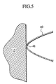
fin 40 on the left side of the pseudo heat exchangingpassage member 15 in the traveling direction of the vehicle (right side in the figure) is not brazed, at apeak 41 of thefin 40, to themember 15 but abutment. - Referring to Fig. 6, the flows of a medium 42 and
oil 43 in theheat exchanger 10 of the embodiment will be described. In Fig. 6, the above-mentionedfins 40 are eliminated in order to clarify such flows of the medium 42 and theoil 43. - As shown in the figure, in the
condenser unit 17 on the "R" side of the figure (i.e. the right side in the traveling direction), the medium 42 flowing into theupper pipe 18 of theupper header pipe 11 passes through thejoint members lower pipe 19 and successively flows in theheat exchanging pipes 38 downwardly. Subsequently, the medium 42 flows from thelower header pipe 12 to theliquid tank 14 and thereafter, the medium 42 flows in theheat exchanging pipes 38 upwardly. After that, the medium 42 is returned to an air-conditioning cycle through thelower pipe 19 of theupper header pipe 11. - On the other hand, in the
oil cooler unit 16 on the "L" side of the figure (i.e. the left side in the traveling direction), theoil 43 entering from theupper pipe 27 of thelower header pipe 12 flows in theheat exchanging tubes 38 upwardly and turns back at thelower pipe 19 of theupper header pipe 11. Subsequently, after flowing in theheat exchanging pipes 38 downwardly, the oil is returned to a transmission through thelower pipe 28 of thelower header pipe 12. Noted that the temperature of the medium 42 flowing thecondenser unit 17 is about 60°C, while the temperature of the oil flowing theoil cooler unit 16 is about 110°C being a remarkable high temperature. - According to the
heat exchanger 10 of the first embodiment, owing to the provision of the pseudo heat exchangingpassage member 15 between theoil cooler unit 16 and thecondenser unit 17, there is almost no heat conduction from theoil cooler unit 16 of high temperature to thecondenser unit 17 of relatively how temperature, whereby the heat exchanging performance of theheat exchanger 10 as a whole can be maintained. Noted that, in the conventional heat exchanger, there is a possibility of heat conduction from an oil cooler unit of high temperature to a condenser unit through the intermediary of a pseudo heat exchanging passage member because the pseudo heat exchanging passage member is welded to fins on respective sides of theoil cooler unit 16 and thecondenser unit 17. While, in accordance with theheat exchanger 10 of this embodiment, by eliminating one fin to be arranged on the right side of the pseudo heat exchanging passage member (closer to the condenser unit 17) and further arranging theabove member 15 having a substantial L-shaped section instead of the fin, the quantity of heat conduction from theoil cooler unit 16 and thecondenser unit 17 can be reduced remarkably. - Generally noted that the elimination of fin(s) would make the flow of cooling wind passing through the
core part 13 smooth thereby reducing the draft resistance too much. Nevertheless, according to this embodiment, the pseudo heat exchangingpassage member 15 having a substantial L-shaped section serves to suppress such an excessive reduction of draft resistance. - The second embodiment of the present invention will be described below. In this embodiment, elements identical to those in the first embodiment will be indicated with the same reference numerals respectively and their overlapping descriptions are eliminated.
- The second embodiment differs from the first embodiment in the shape of the pseudo heat exchanging passage member.
- As shown in Fig. 7, a
heat exchanger 45 is also provided with a pseudo heat exchangingpassage member 44 whose upper end 44a has a width substantially equal to the width of theheat exchanging tube 38, which is similar to the pseudo heat exchangingpassage member 15 of the first embodiment. As shown in Fig. 8, the pseudo heat exchangingpassage member 44 further includes alateral part 44b extending rearward of the vehicle and afront part 44c extending to the right direction of the vehicle, both of which are formed into one body, providing the substantial L-shaped section. Additionally, thefront part 44c is provided, at a tip thereof, with a plurality ofprojections 44d which abut on the adjoiningheat exchanging tube 38. - According to the
heat exchanger 45 constructed above, owing to the formation of theprojections 44d, it is possible to reduce a contact area of the pseudo heat exchangingpassage member 44 with the adjoiningheat exchanging tube 38 in comparison with the contact area of the first embodiment, whereby the quantity of heat conduction from theoil cooler unit 16 to thecondenser unit 17 can be reduced furthermore. - The third embodiment of the present invention will be described below. In this embodiment, elements identical to those in the second embodiment will be indicated with the same reference numerals respectively and their overlapping descriptions are eliminated.
- The third embodiment differs from the second embodiment in the shape of the pseudo heat exchanging passage member.
- As shown in Fig. 9, a heat exchanger 46 is also provided with a pseudo heat exchanging
passage member 47 whose upper end 47a has a width substantially equal to the width of theheat exchanging tube 38, which is similar to the pseudo heat exchangingpassage members passage member 47 further includes arear part 47b arranged on the rear side of the vehicle to extend to the right in the vehicle's traveling direction (left in the figure), abody part 47c extending from the left end (right in the figure) of thepart 47b to the forward of the vehicle and afront part 47d extending from the front end of thepart 47c to the left in the vehicle's traveling direction (right in the figure), all of which are formed into one body, providing a substantial Z-shaped section. Additionally, the right end (left in the figure) of therear part 47b and the left end (right in the figure) of thefront part 47d are arranged apart from the adjoiningheat exchanging tubes 38 at intervals, respectively. As one modification, the right end of therear part 47b and the left end of thefront part 47d may be arranged so as to abut on the adjoiningheat exchanging tubes 38. - According to the heat exchanger 46 constructed above, there are eliminated left and right fins to be arranged on both sides of the boundary between the
oil cooler unit 16 and thecondenser unit 17 and one heat exchanging tube to be arranged between these left and right fins, while there is provided the pseudo heat exchangingpassage member 47 having a substantial Z-shaped section instead of these fins and the heat exchanging tube therebetween. Again, since both left and right ends of the pseudo heat exchangingpassage member 47 do not abut on the adjoiningheat exchanging tubes oil cooler unit 16 to thecondenser unit 17 is reduced furthermore. Even if arranging the right end of therear part 47b and the left end of thefront part 47d so as to abut on the adjoiningheat exchanging tubes 38 in the above modification, it is possible to reduce the quantity of heat conduction from theoil cooler unit 16 to thecondenser unit 17 since the pseudo heat exchangingpassage member 47 is not brazed to the adjoiningheat exchanging tubes passage member 47 having a substantial Z-shaped section allows an excessive reduction in draft resistance to be suppressed. - Finally, it will be understood by those skilled in the art that the foregoing descriptions are nothing but three embodiments of the disclosed heat exchanger and therefore, various changes and modifications may be made within the scope of claims. For example, in the modification of the compound type heat exchanger 46 of the third embodiment, the pseudo heat exchanging
passage member 47 may be provided, at the right end of therear part 47b and the left end of thefront end 47d, with projections abutting on the adjoiningheat exchanging tubes
Claims (6)
- A compound type heat exchanger, comprising:wherein the core part and the header pipes are divided in a direction perpendicular to the laminating direction of the heat exchanging tubes and the fins at a boundary of the pseudo heat exchanging passage member into a first heat exchange unit and a second heat exchange unit.a core part having a plurality of heat exchanging tubes each formed to allow passage of a heat exchanging medium therein, the heat exchanging tubes being juxtaposed to each other, and a plurality of fins each interposed between the adjoining heat exchanging tubes so that the heat exchanging tubes and the fins are laminated alternately;a pair of header pipes arranged on both ends of the heat exchanging tubes and connected to respective ends of the heat exchanging tubes;a pseudo heat exchanging passage member formed so as not to allow passage of the heat exchanging medium therein and arranged so as to substitute for a specified heat exchanging tube of the heat exchanging tubes and a fin adjoining the specified heat exchanging tube on either left or right side thereof, the pseudo heat exchanging passage member having a substantially L-shaped section; andpartition walls each arranged in the header pipes so as to be close to the pseudo heat exchanging passage member thereby to divide spaces inside the header pipes in a direction perpendicular to the longitudinal direction of the header pipes,
- The compound type heat exchanger of claim 1, wherein
the pseudo heat exchanging passage member is provided, on one side thereof in the laminating direction, with projections that abut on the heat exchanging tube adjoining the pseudo heat exchanging passage member. - A compound type heat exchanger, comprising:wherein the core part and the header pipes are divided in a direction perpendicular to the laminating direction of the heat exchanging tubes and the fins at a boundary of the pseudo heat exchanging passage member into a first heat exchanging unit and a second heat exchanging unit.a core part having a plurality of heat exchanging tubes each formed to allow passage of a heat exchanging medium therein, the heat exchanging tubes being juxtaposed to each other, and a plurality of fins each interposed between the adjoining heat exchanging tubes so that the heat exchanging tubes and the fins are laminated alternately;a pair of header pipes arranged on both ends of the heat exchanging tubes and also connected to respective ends of the heat exchanging tubes;a pseudo heat exchanging passage member formed so as not to allow passage of the heat exchanging medium therein and arranged so as to substitute for a specified heat exchanging tube of the heat exchanging tubes and a fin adjoining the specified heat exchanging tube on either left or right side thereof, the pseudo heat exchanging passage member having a substantially Z-shaped section; andpartition walls each arranged in the header pipes so as to be close to the pseudo heat exchanging passage member thereby to divide spaces inside the header pipes in a direction perpendicular to the longitudinal direction of the header pipes,
- The compound type heat exchanger of claim 3, wherein
the pseudo heat exchanging passage member is arranged so that both side thereof in the laminating direction do not abut on the heat exchanging tubes adjoining the pseudo heat exchanging passage member. - The compound type heat exchanger of claim 3, wherein
the pseudo heat exchanging passage member is provided, on one end thereof in the laminating direction, with projections that abut on the heat exchanging tube adjoining the pseudo heat exchanging passage member. - The compound type heat exchanger of claim 1, wherein
each of the heat exchanging tubes is covered with a cladding layer of brazing material.
Applications Claiming Priority (2)
| Application Number | Priority Date | Filing Date | Title |
|---|---|---|---|
| JP2003137645A JP2004340486A (en) | 2003-05-15 | 2003-05-15 | Complex heat exchanger |
| JP2003137645 | 2003-05-15 |
Publications (2)
| Publication Number | Publication Date |
|---|---|
| EP1477760A2 true EP1477760A2 (en) | 2004-11-17 |
| EP1477760A3 EP1477760A3 (en) | 2008-03-12 |
Family
ID=33028401
Family Applications (1)
| Application Number | Title | Priority Date | Filing Date |
|---|---|---|---|
| EP04011569A Withdrawn EP1477760A3 (en) | 2003-05-15 | 2004-05-14 | Compound type heat exchanger |
Country Status (3)
| Country | Link |
|---|---|
| US (1) | US7036571B2 (en) |
| EP (1) | EP1477760A3 (en) |
| JP (1) | JP2004340486A (en) |
Cited By (3)
| Publication number | Priority date | Publication date | Assignee | Title |
|---|---|---|---|---|
| WO2007027354A1 (en) * | 2005-08-31 | 2007-03-08 | Valeo, Inc. | Heat exchanger |
| WO2007014560A3 (en) * | 2005-08-04 | 2007-03-22 | Visteon Global Tech Inc | Multiple flow heat exchanger |
| US7360584B2 (en) | 2004-11-19 | 2008-04-22 | Modine Manufacturing Company | Thermal relief mechanism for combination-type heat exchangers |
Families Citing this family (9)
| Publication number | Priority date | Publication date | Assignee | Title |
|---|---|---|---|---|
| US20080023185A1 (en) * | 2006-07-25 | 2008-01-31 | Henry Earl Beamer | Heat exchanger assembly |
| US7484555B2 (en) * | 2006-07-25 | 2009-02-03 | Delphi Technologies, Inc. | Heat exchanger assembly |
| US8225853B2 (en) * | 2006-10-13 | 2012-07-24 | Carrier Corporation | Multi-pass heat exchangers having return manifolds with distributing inserts |
| WO2015142615A1 (en) | 2014-03-18 | 2015-09-24 | Carrier Corporation | Microchannel heat exchanger evaporator |
| KR101226687B1 (en) * | 2010-08-16 | 2013-01-25 | 이일재 | Heat exchanger with joining-branch tank to join for header pipe |
| KR101919106B1 (en) * | 2012-08-24 | 2018-11-19 | 한온시스템 주식회사 | Outdoor heat exchanger |
| WO2014184916A1 (en) * | 2013-05-15 | 2014-11-20 | 三菱電機株式会社 | Laminated header, heat exchanger, and air conditioner |
| JP6746234B2 (en) * | 2017-01-25 | 2020-08-26 | 日立ジョンソンコントロールズ空調株式会社 | Heat exchanger and air conditioner |
| WO2026088417A1 (en) * | 2024-10-25 | 2026-04-30 | 三菱電機株式会社 | Heat exchanger |
Citations (1)
| Publication number | Priority date | Publication date | Assignee | Title |
|---|---|---|---|---|
| JP2000018880A (en) | 1998-06-23 | 2000-01-18 | Showa Alum Corp | Integrated heat exchanger |
Family Cites Families (12)
| Publication number | Priority date | Publication date | Assignee | Title |
|---|---|---|---|---|
| US2505790A (en) * | 1946-07-24 | 1950-05-02 | Perfex Corp | Combination radiator and oil cooler |
| JPH08327285A (en) * | 1995-05-30 | 1996-12-13 | Sanden Corp | Multi-tube heat exchanger |
| CN1199458A (en) * | 1996-08-29 | 1998-11-18 | 株式会社杰克塞尔 | Heat exchanger |
| DE19729239A1 (en) * | 1997-07-09 | 1999-01-14 | Behr Gmbh & Co | Finned-tube block for heat transfer unit |
| FR2786259B1 (en) * | 1998-11-20 | 2001-02-02 | Valeo Thermique Moteur Sa | COMBINED HEAT EXCHANGER, PARTICULARLY FOR A MOTOR VEHICLE |
| FR2788118B1 (en) * | 1998-12-30 | 2003-04-18 | Valeo Climatisation | HEATING, VENTILATION AND / OR AIR CONDITIONING DEVICE COMPRISING A THERMAL BURNER EQUIPPED WITH AN EVAPORATOR |
| KR20010068204A (en) * | 2000-07-03 | 2001-07-23 | 배길훈 | Head assembly of heat exchange for vehicle |
| US6938675B2 (en) * | 2000-10-11 | 2005-09-06 | Denso Corporation | Heat exchanger |
| JP3903136B2 (en) * | 2001-11-05 | 2007-04-11 | 株式会社小松製作所 | Construction machine cooling system |
| US6793012B2 (en) * | 2002-05-07 | 2004-09-21 | Valeo, Inc | Heat exchanger |
| US6883600B2 (en) * | 2002-05-16 | 2005-04-26 | Denso Corporation | Heat exchanger with dual heat-exchanging portions |
| AU2003241693A1 (en) * | 2002-06-18 | 2003-12-31 | Showa Denko K.K. | Unit-type heat exchanger |
-
2003
- 2003-05-15 JP JP2003137645A patent/JP2004340486A/en active Pending
-
2004
- 2004-05-10 US US10/842,155 patent/US7036571B2/en not_active Expired - Fee Related
- 2004-05-14 EP EP04011569A patent/EP1477760A3/en not_active Withdrawn
Patent Citations (1)
| Publication number | Priority date | Publication date | Assignee | Title |
|---|---|---|---|---|
| JP2000018880A (en) | 1998-06-23 | 2000-01-18 | Showa Alum Corp | Integrated heat exchanger |
Cited By (4)
| Publication number | Priority date | Publication date | Assignee | Title |
|---|---|---|---|---|
| US7360584B2 (en) | 2004-11-19 | 2008-04-22 | Modine Manufacturing Company | Thermal relief mechanism for combination-type heat exchangers |
| WO2007014560A3 (en) * | 2005-08-04 | 2007-03-22 | Visteon Global Tech Inc | Multiple flow heat exchanger |
| US8561681B2 (en) | 2005-08-04 | 2013-10-22 | Visteon Global Technologies, Inc. | Multiple flow heat exchanger |
| WO2007027354A1 (en) * | 2005-08-31 | 2007-03-08 | Valeo, Inc. | Heat exchanger |
Also Published As
| Publication number | Publication date |
|---|---|
| US20050006081A1 (en) | 2005-01-13 |
| US7036571B2 (en) | 2006-05-02 |
| EP1477760A3 (en) | 2008-03-12 |
| JP2004340486A (en) | 2004-12-02 |
Similar Documents
| Publication | Publication Date | Title |
|---|---|---|
| EP0855566B1 (en) | Integrated heat exchanger | |
| JP4280545B2 (en) | Combined heat exchanger | |
| US7036571B2 (en) | Compound type heat exchanger | |
| US6283200B1 (en) | Heat exchanger having header tank increased in volume in the vicinity of pipe connected thereto | |
| US7077193B2 (en) | Compound type heat exchanger | |
| JP2000018880A (en) | Integrated heat exchanger | |
| JP4625687B2 (en) | Heat exchanger | |
| US7328739B2 (en) | Heat exchanger for vehicle | |
| JPH05312492A (en) | Heat exchanger | |
| JPH0345300B2 (en) | ||
| US6302195B1 (en) | Heat exchanger | |
| US7025128B2 (en) | Compound type heat exchanger | |
| JPH11153395A (en) | Integrated heat exchanger for automobiles | |
| JP3683001B2 (en) | Double stacked heat exchanger | |
| JP2007078292A (en) | Heat exchanger and double heat exchanger | |
| JPH11223486A (en) | Side-by-side integrated heat exchanger and method of manufacturing the same | |
| GB2375816A (en) | A heat exchanger for a vehicle | |
| JP2005249332A (en) | Double heat exchanger | |
| JPH0345301B2 (en) | ||
| WO1999028692A1 (en) | Parallel-arranged unitary type heat exchangers and method of manufacturing the same | |
| JP5525805B2 (en) | Heat exchanger | |
| JPH01291098A (en) | Mounting device for outlet pipe and inlet pipe in heat exchanger | |
| JP2006207944A (en) | Heat exchanger | |
| KR100988319B1 (en) | heat transmitter | |
| JP2005188382A (en) | Double heat exchanger |
Legal Events
| Date | Code | Title | Description |
|---|---|---|---|
| PUAI | Public reference made under article 153(3) epc to a published international application that has entered the european phase |
Free format text: ORIGINAL CODE: 0009012 |
|
| AK | Designated contracting states |
Kind code of ref document: A2 Designated state(s): AT BE BG CH CY CZ DE DK EE ES FI FR GB GR HU IE IT LI LU MC NL PL PT RO SE SI SK TR |
|
| AX | Request for extension of the european patent |
Extension state: AL HR LT LV MK |
|
| PUAL | Search report despatched |
Free format text: ORIGINAL CODE: 0009013 |
|
| AK | Designated contracting states |
Kind code of ref document: A3 Designated state(s): AT BE BG CH CY CZ DE DK EE ES FI FR GB GR HU IE IT LI LU MC NL PL PT RO SE SI SK TR |
|
| AX | Request for extension of the european patent |
Extension state: AL HR LT LV MK |
|
| 17P | Request for examination filed |
Effective date: 20080520 |
|
| AKX | Designation fees paid |
Designated state(s): DE FR GB |
|
| STAA | Information on the status of an ep patent application or granted ep patent |
Free format text: STATUS: THE APPLICATION HAS BEEN WITHDRAWN |
|
| 18W | Application withdrawn |
Effective date: 20090429 |