EP1477680A2 - Scroll compressor - Google Patents
Scroll compressor Download PDFInfo
- Publication number
- EP1477680A2 EP1477680A2 EP04018132A EP04018132A EP1477680A2 EP 1477680 A2 EP1477680 A2 EP 1477680A2 EP 04018132 A EP04018132 A EP 04018132A EP 04018132 A EP04018132 A EP 04018132A EP 1477680 A2 EP1477680 A2 EP 1477680A2
- Authority
- EP
- European Patent Office
- Prior art keywords
- lubricant
- oil
- compressor
- sump
- shell
- Prior art date
- Legal status (The legal status is an assumption and is not a legal conclusion. Google has not performed a legal analysis and makes no representation as to the accuracy of the status listed.)
- Withdrawn
Links
Images


Classifications
-
- F—MECHANICAL ENGINEERING; LIGHTING; HEATING; WEAPONS; BLASTING
- F04—POSITIVE - DISPLACEMENT MACHINES FOR LIQUIDS; PUMPS FOR LIQUIDS OR ELASTIC FLUIDS
- F04C—ROTARY-PISTON, OR OSCILLATING-PISTON, POSITIVE-DISPLACEMENT MACHINES FOR LIQUIDS; ROTARY-PISTON, OR OSCILLATING-PISTON, POSITIVE-DISPLACEMENT PUMPS
- F04C28/00—Control of, monitoring of, or safety arrangements for, pumps or pumping installations specially adapted for elastic fluids
- F04C28/24—Control of, monitoring of, or safety arrangements for, pumps or pumping installations specially adapted for elastic fluids characterised by using valves controlling pressure or flow rate, e.g. discharge valves or unloading valves
- F04C28/26—Control of, monitoring of, or safety arrangements for, pumps or pumping installations specially adapted for elastic fluids characterised by using valves controlling pressure or flow rate, e.g. discharge valves or unloading valves using bypass channels
- F04C28/265—Control of, monitoring of, or safety arrangements for, pumps or pumping installations specially adapted for elastic fluids characterised by using valves controlling pressure or flow rate, e.g. discharge valves or unloading valves using bypass channels being obtained by displacing a lateral sealing face
-
- F—MECHANICAL ENGINEERING; LIGHTING; HEATING; WEAPONS; BLASTING
- F04—POSITIVE - DISPLACEMENT MACHINES FOR LIQUIDS; PUMPS FOR LIQUIDS OR ELASTIC FLUIDS
- F04C—ROTARY-PISTON, OR OSCILLATING-PISTON, POSITIVE-DISPLACEMENT MACHINES FOR LIQUIDS; ROTARY-PISTON, OR OSCILLATING-PISTON, POSITIVE-DISPLACEMENT PUMPS
- F04C18/00—Rotary-piston pumps specially adapted for elastic fluids
- F04C18/02—Rotary-piston pumps specially adapted for elastic fluids of arcuate-engagement type, i.e. with circular translatory movement of co-operating members, each member having the same number of teeth or tooth-equivalents
- F04C18/0207—Rotary-piston pumps specially adapted for elastic fluids of arcuate-engagement type, i.e. with circular translatory movement of co-operating members, each member having the same number of teeth or tooth-equivalents both members having co-operating elements in spiral form
- F04C18/0215—Rotary-piston pumps specially adapted for elastic fluids of arcuate-engagement type, i.e. with circular translatory movement of co-operating members, each member having the same number of teeth or tooth-equivalents both members having co-operating elements in spiral form where only one member is moving
-
- F—MECHANICAL ENGINEERING; LIGHTING; HEATING; WEAPONS; BLASTING
- F04—POSITIVE - DISPLACEMENT MACHINES FOR LIQUIDS; PUMPS FOR LIQUIDS OR ELASTIC FLUIDS
- F04C—ROTARY-PISTON, OR OSCILLATING-PISTON, POSITIVE-DISPLACEMENT MACHINES FOR LIQUIDS; ROTARY-PISTON, OR OSCILLATING-PISTON, POSITIVE-DISPLACEMENT PUMPS
- F04C23/00—Combinations of two or more pumps, each being of rotary-piston or oscillating-piston type, specially adapted for elastic fluids; Pumping installations specially adapted for elastic fluids; Multi-stage pumps specially adapted for elastic fluids
- F04C23/008—Hermetic pumps
-
- F—MECHANICAL ENGINEERING; LIGHTING; HEATING; WEAPONS; BLASTING
- F04—POSITIVE - DISPLACEMENT MACHINES FOR LIQUIDS; PUMPS FOR LIQUIDS OR ELASTIC FLUIDS
- F04C—ROTARY-PISTON, OR OSCILLATING-PISTON, POSITIVE-DISPLACEMENT MACHINES FOR LIQUIDS; ROTARY-PISTON, OR OSCILLATING-PISTON, POSITIVE-DISPLACEMENT PUMPS
- F04C28/00—Control of, monitoring of, or safety arrangements for, pumps or pumping installations specially adapted for elastic fluids
- F04C28/28—Safety arrangements; Monitoring
-
- F—MECHANICAL ENGINEERING; LIGHTING; HEATING; WEAPONS; BLASTING
- F04—POSITIVE - DISPLACEMENT MACHINES FOR LIQUIDS; PUMPS FOR LIQUIDS OR ELASTIC FLUIDS
- F04C—ROTARY-PISTON, OR OSCILLATING-PISTON, POSITIVE-DISPLACEMENT MACHINES FOR LIQUIDS; ROTARY-PISTON, OR OSCILLATING-PISTON, POSITIVE-DISPLACEMENT PUMPS
- F04C29/00—Component parts, details or accessories of pumps or pumping installations, not provided for in groups F04C18/00 - F04C28/00
- F04C29/0007—Injection of a fluid in the working chamber for sealing, cooling and lubricating
-
- F—MECHANICAL ENGINEERING; LIGHTING; HEATING; WEAPONS; BLASTING
- F04—POSITIVE - DISPLACEMENT MACHINES FOR LIQUIDS; PUMPS FOR LIQUIDS OR ELASTIC FLUIDS
- F04C—ROTARY-PISTON, OR OSCILLATING-PISTON, POSITIVE-DISPLACEMENT MACHINES FOR LIQUIDS; ROTARY-PISTON, OR OSCILLATING-PISTON, POSITIVE-DISPLACEMENT PUMPS
- F04C29/00—Component parts, details or accessories of pumps or pumping installations, not provided for in groups F04C18/00 - F04C28/00
- F04C29/02—Lubrication; Lubricant separation
- F04C29/023—Lubricant distribution through a hollow driving shaft
-
- F—MECHANICAL ENGINEERING; LIGHTING; HEATING; WEAPONS; BLASTING
- F04—POSITIVE - DISPLACEMENT MACHINES FOR LIQUIDS; PUMPS FOR LIQUIDS OR ELASTIC FLUIDS
- F04C—ROTARY-PISTON, OR OSCILLATING-PISTON, POSITIVE-DISPLACEMENT MACHINES FOR LIQUIDS; ROTARY-PISTON, OR OSCILLATING-PISTON, POSITIVE-DISPLACEMENT PUMPS
- F04C29/00—Component parts, details or accessories of pumps or pumping installations, not provided for in groups F04C18/00 - F04C28/00
- F04C29/02—Lubrication; Lubricant separation
- F04C29/026—Lubricant separation
-
- F—MECHANICAL ENGINEERING; LIGHTING; HEATING; WEAPONS; BLASTING
- F04—POSITIVE - DISPLACEMENT MACHINES FOR LIQUIDS; PUMPS FOR LIQUIDS OR ELASTIC FLUIDS
- F04C—ROTARY-PISTON, OR OSCILLATING-PISTON, POSITIVE-DISPLACEMENT MACHINES FOR LIQUIDS; ROTARY-PISTON, OR OSCILLATING-PISTON, POSITIVE-DISPLACEMENT PUMPS
- F04C2210/00—Fluid
- F04C2210/10—Fluid working
- F04C2210/105—Helium (He)
-
- F—MECHANICAL ENGINEERING; LIGHTING; HEATING; WEAPONS; BLASTING
- F04—POSITIVE - DISPLACEMENT MACHINES FOR LIQUIDS; PUMPS FOR LIQUIDS OR ELASTIC FLUIDS
- F04C—ROTARY-PISTON, OR OSCILLATING-PISTON, POSITIVE-DISPLACEMENT MACHINES FOR LIQUIDS; ROTARY-PISTON, OR OSCILLATING-PISTON, POSITIVE-DISPLACEMENT PUMPS
- F04C2240/00—Components
- F04C2240/60—Shafts
- F04C2240/603—Shafts with internal channels for fluid distribution, e.g. hollow shaft
-
- F—MECHANICAL ENGINEERING; LIGHTING; HEATING; WEAPONS; BLASTING
- F04—POSITIVE - DISPLACEMENT MACHINES FOR LIQUIDS; PUMPS FOR LIQUIDS OR ELASTIC FLUIDS
- F04C—ROTARY-PISTON, OR OSCILLATING-PISTON, POSITIVE-DISPLACEMENT MACHINES FOR LIQUIDS; ROTARY-PISTON, OR OSCILLATING-PISTON, POSITIVE-DISPLACEMENT PUMPS
- F04C2270/00—Control; Monitoring or safety arrangements
- F04C2270/24—Level of liquid, e.g. lubricant or cooling liquid
Definitions
- the present invention relates generally to a scroll-type machine and more specifically to a scroll-type machine specifically adapted for use in either cryogenic applications utilizing helium as the refrigerant or as an air compressor.
- the present invention comprises a scroll compressor, which is specifically adapted for use in the compression of both helium and air which in addition to the conventional low pressure oil sump, also includes a second high pressure oil sump in the discharge chamber.
- the oil from the low pressure oil sump is circulated to the bearings and other moving parts in a manner similar to that of conventional scroll compressors.
- oil from the high pressure oil sump is directed through an external heat exchanger for cooling and then injected into the compression pockets to aid in cooling of the compressor as well as to assist in sealing of the wraps and lubricating same.
- An oil separator is provided in the discharge chamber of the compressor to remove at least a portion of the injected oil from the compressed gas to thereby replenish the high pressure oil sump.
- a unique level control arrangement is also provided to prevent excess accumulation of oil in the high pressure oil sump. Relatively large volumes of oil must be circulated in this manner to prevent overheating of the compressor during operation as well as to aid in lubrication thereof. It should be noted that in such cryogenic applications it is exceedingly important that the refrigerant (i.e. helium) be virtually oil free and hence it is common for such systems to employ multiple external oil separators to ensure complete removal of the oil injected during the compression process. This is also true in many applications in which compressed air is utilized.
- Compressor 10 includes an outer shell 12 within which is disposed a compressor assembly including an orbiting scroll member 14 having an end plate 16 from which a spiral wrap 18 extends, a non-orbiting scroll member 20 having an end plate 22 from which a spiral wrap 24 extends and a main bearing housing 26 supportingly secured to outer shell 12.
- Main bearing housing 26 supports orbiting scroll member 14 and non-orbiting scroll member 20 is axially movably secured thereto with respective wraps 18 and 24 positioned in meshing engagement such that as orbiting scroll member 14 orbits, the wraps will define moving fluid pockets that decrease in size as they move toward the center of the scroll members.
- a driving motor 28 is also provided in the lower portion of shell 12 including a stator 30 supported by shell 12 and a rotor 32 secured to and drivingly connected to drive shaft 34.
- Drive shaft 34 is drivingly connected to orbiting scroll member 14 via eccentric pin 36 and drive bushing 38 and is rotatably supported by upper bearing housing 26 and a lower bearing housing 40 which is also secured to shell 12.
- the lower end of drive shaft 34 extends into an oil sump 42 provided in the bottom of shell 12.
- a reverse rotation prevention and lower counterweight shield assembly 44 is also supported on drive shaft 34 between lower bearing 40 and motor assembly 28 and serves to restrict reverse rotation of the compressor on shut down as well as to restrict flow of oil to the area around the lower end of the rotor.
- an Oldham coupling 45 is provided being supported on main bearing housing 26 and interconnecting with both orbiting scroll member 14 and non-orbiting scroll member 20.
- an oil pump is provided in the lower end of drive shaft 34 which serves to direct oil axially upwardly through an eccentric axially extending passage 43 in drive shaft 34.
- Radial passages may be provided to supply lubricant to the main bearing and/or lower bearing and a portion of the oil will be discharged from the top of eccentric pin 36 to lubricate the interface with drive bushing 38 and the interface between drive bushing 38 and orbiting scroll member 14.
- a partition or muffler plate 46 is also provided extending across the interior of shell 12 and is sealingly secured thereto around its periphery. Muffler plate 46 serves to divide the interior of shell 12 into a lower suction chamber 48 and an upper discharge chamber 50.
- suction gas will be drawn into suction chamber 48 of compressor 10 through suction inlet 52 and into the moving fluid pockets defined by scroll wraps 18 and 24 and end plates 16 and 22.
- the fluid pockets will move inwardly decreasing in size and thereby compressing the fluid.
- the compressed fluid will be discharged into discharge chamber 50 through discharge port 54 and passage 56 provided in non-orbiting scroll member 20 and discharge fitting assembly 58 secured to muffler plate 46.
- the compressed fluid then exits compressor 10 through discharge outlet 59.
- a pressure biasing chamber 60 is provided in the upper surface of non-orbiting scroll member 20.
- a floating seal 62 is positioned within chamber 60 and cooperates with muffler plate 46 to prevent leakage of discharge gas flowing into discharge chamber 50 from discharge port 54.
- Biasing chamber 60 is pressurized by fluid at intermediate pressure supplied from the fluid pockets under compression via passages (not shown) in non-orbiting scroll 20.
- compressor 10 as thus far described is similar to and incorporates features described in greater detail in assignee's patents numbers 4,877,382; 5,156,539; 5,102,316; 5,320,506; and 5,320,507 the disclosures of which are hereby incorporated by reference.
- compressor 10 is specifically adapted for use with helium as a refrigerant. Because of the nature of helium, the compression of same in a refrigeration compressor results in the generation of significantly higher temperatures. In order to prevent these temperatures from becoming excessive, it is necessary to circulate substantially greater quantities of oil to the various components than typically is necessary when other more common refrigerants are utilized and to supply oil to the compression chambers as well. In addition to the need for the circulation of large quantities of oil, it is also very important that substantially all oil be removed from the compressed helium before it is supplied to the refrigeration or cryogenic system.
- the compressor of the present intention incorporates a generally radially extending passage 64 in the end plate of orbiting scroll member 14. Passage 64 at its inner end opens into the chamber defined by hub 66 provided on orbiting scroll member 14 in which bushing 38 and eccentric pin 36 are disposed. The outer end of passage 64 is plugged and an axially extending passage 68 extends upwardly therefrom and opens into the flow of suction gas entering the compression pockets of the compressor. Passages 64 and 68 thus serve to direct a portion of the oil being thrown out of the top of eccentric pin 36 to the suction gas flowing into the compression pockets.
- end plate 22 of non-orbiting scroll member 20 is provided with a pair of generally chordally extending passages 70 and 72 the inner ends of which communicate with respective axial passages 74 and 76 opening into a pair of diametrically opposed fluid pockets which pockets are undergoing compression and hence at a pressure between suction and discharge.
- the outer ends of passages 70 and 72 merge into a single passage 78 which opens outwardly through a sidewall of the end plate 22 of non-orbiting scroll 20.
- a fitting 80 is secured to the sidewall of end plate 22 and defines a passage 82 leading from an oil inlet fitting 84 secured to outer shell 12 to passage 78.
- fitting 80 is formed in two pieces with lower portion 86 being slidably telescopically received within the lower end of upper portion 88. Suitable sealing means such as an O-ring will preferably be provided between upper and lower portions 86 and 88.
- a relatively short tubular member 90 serves to sealingly interconnect oil inlet fitting 84 with lower portion 86 of fitting 80.
- main bearing housing is provided with a plurality of generally radially extending passages 92 which serve to direct oil accumulating in recess 94 outwardly to Oldham coupling 45.
- Discharge fitting 58 includes an upper tubular member 96 having a relatively large diameter threaded bore 98 opening inwardly from the lower end thereof and a depending locating flange portion 100 which is received within an opening 102 provided in muffler plate 46.
- a threaded flanged retainer 104 is received within bore 98 and serves to sealingly secure discharge fitting 58 to muffler plate 46 and to define a flowpath for discharge gas from discharge passage 56 into discharge chamber 50.
- Discharge fitting 58 supports an oil separator plate 106 secured to the upper end thereof in overlying relationship to outlet openings 108.
- Oil separator plate 106 extends radially outwardly from fitting 58 and includes a plurality of radially spaced annular depending flange portions 110 that serve to provide a tortuous flowpath for the discharge gas and thereby aid in separation of entrained oil.
- Oil separated from the discharge gas by separator plate 106 will accumulate in the lower portion of discharge chamber 50.
- an oil outlet fitting 112 is provided being secured to shell 12 so as to open into a lower portion of discharge chamber 50 which defines an upper oil sump. Oil from outlet fitting 112 is supplied to oil inlet fitting 84 as described in greater detail below.
- Oil return assembly 114 In order to prevent excessive accumulation of oil in discharge chamber 50, a lubricant level oil return assembly 114 is provided which operates to return excessive oil to lower sump 42 through muffler plate 46.
- Oil return assembly 114 includes a through fitting 116 sealingly secured to and extending through muffler plate 46 adjacent an outer peripheral edge thereof from which a tube 118 extends to discharge fitting 58.
- Return fitting 116 defines a passage 128 extending therethrough which opens into the lower pressure suction chamber 48 via opening 130. If desired, a suitable filter may be provided within passage 128 to prevent any particles from being returned to the lower sump.
- Discharge fitting 58 includes a passage 120 extending axially downward from the upper end thereof and communicating at its lower end with a radially inwardly extending passage 122 via a restricted portion 124.
- the upper end of passage 120 is sealed off with a suitable plug 123.
- Tube 118 communicates with axially extending passage 120 via a second radially extending passage 126 located above radial passage 122.
- passage 120 in open communication with the compressed gas in discharge chamber 50.
- restrictor 124 be located downstream of passage 120, i.e., in passage 126, tube 118 or through fitting 116.
- passage 120 will preferably be located substantially coaxial with the axial center of compressor 10. This will ensure that opening of restrictor 124 and/or passage 126 into passage 120 is in close proximity to the center axis 129 of the compressor and will greatly reduce the effect of tilting of compressor 10 on the level of oil retained in the discharge chamber 50.
- baffle member 132 is secured to shell 12 in overlying relationship to the inner end of discharge outlet 59.
- baffle member 132 may be in the form of a box having an opening 134 on the top sidewall thereof and an open end 136 which is sealingly secured to the inner surface of shell 12.
- baffle member 132 may be cylindrical in shape with one end closed and opening 134 being oriented so as to face upwardly away from the upper surface of the lubricant in discharge chamber 50.
- compressor 10 is shown incorporated in a refrigeration or cryogenic circuit specifically designed for use of helium as a refrigerant.
- compressed helium flows from compressor 10 via line 138 to a heat exchanger 140 which serves to separate oil therefrom.
- the compressed helium is routed serially through additional oil separators 142 to ensure substantially complete removal of entrained oil therefrom after which it is directed to a condenser 144 and then to additional system components (not shown) such as an evaporator and then returned to compressor 10 via line 141.
- Oil collected in discharge chamber 50 is directed from oil outlet 112 to a heat exchanger 146 via line 148 for cooling.
- Oil from heat exchanger 146 together with separated oil from heat exchanger 140 and oil separators 142 is then supplied to oil inlet fitting 84 via line 143 from which it is directed to the respective fluid pockets under compression. Because this oil is at substantially discharge pressure, oil will easily be caused to flow into the desired fluid pockets under compression which will be at a pressure above suction pressure but below discharge pressure. As shown, suitable check valves 150 are included at both discharge outlet 59 and oil outlet 112 to prevent undesired reverse flow of fluids. Additionally, lubricant separated in heat exchanger 140 as well as lubricant separators 142 will also be supplied to oil inlet fitting 84 via line 145 for injection into the moving fluid pockets.
- compressor 10 is designed to provide a high volume of oil flow to the compressor to both lubricate the various portions thereof as well as to ensure adequate cooling of the compressor. Additionally, compressor 10 includes an integral oil separator to aid in removal of the oil from the compressed refrigerant as well as to ensure an adequate supply of oil for injection into the compressor. Additionally, the provision for oil injection into the suction inlet provides insurance that the level of oil in the discharge chamber will be maintained whereas the overflow arrangement prevents this level from becoming excessively high.
- compressor 152 is substantially identical to compressor 10 including without limitation both the oil injection into the fluid pockets under compression, the injection of oil into the suction gas flowing to the compression pockets and the internal oil separator incorporated in compressor 10 as shown in Figure 1. Accordingly, corresponding portions thereof have been indicated by the same reference numbers primed.
- compressor 152 In place of the suction inlet 52 incorporated in compressor 10, compressor 152 includes an inlet assembly 154 which includes conduit 156 secured to the outer shell 12' which is adapted to receive a threaded connection for suction inlet conduit 158.
- a suction filter assembly 160 which may also include a muffler if desired, is secured to the other end of conduit 158 and serves to filter out particulate matter that could result in excessive wear as well as to muffle possible noise of the air being drawn into compressor 152.
- discharge fitting 162 of compressor 152 includes a restricted opening 164 at its inner end. Restricted opening 164 serves to restrict the flow of compressed air out of discharge chamber 50' which is particuiarly important during periods of compressor operation in which the back pressure loading is at zero or very low as this build up of discharge pressure in chamber 50' acts together with the intermediate pressure in biasing chamber 60' to bias the non-orbiting scroll member 20' axially into sealing engagement with orbiting scroll member 14'.
- a plurality of springs are provided in biasing chamber 60' acting between a lower surface of seal 62' and the bottom surface of biasing chamber 60'.
- restrictor 164 in discharge fitting 162 will not appreciably reduce system efficiency because during normal operation, the density of the compressed air flowing therethrough will be substantially greater than at low pressure operation.
- compressor 152 incorporates a modified arrangement for preventing accumulation of excessive oil in the discharge chamber.
- compressor 152 includes an elongated member 166 extending axially inwardly through a suitable fitting 168 provided on the top portion of outer shell 12' and having a lower end 170 threadedly received in a threaded opening 172 provided in muffler plate 46'.
- elongated member is provided with a shoulder 174 adjacent the upper end against which a suitable O-ring 176 is seated.
- a second shoulder 178 is provided against which O-ring 180 is seated.
- Elongated member 166 comprises an upper member 182 having an axially extending bore 184 provided therein and a plurality of circumferentially spaced radial bores 186 opening into bore 184 adjacent the upper end thereof.
- a lower member 188 is also provided having reduced diameter portion 190 provided at the upper end thereof which is sized to be threadedly received in bore 184 of upper member 182.
- a central bore 192 extends axially from the upper end of lower member 188 forming a continuation of bore 184 and terminates adjacent the lower end where a restricted opening 194 is provided opening outwardly from the bottom of lower member 188.
- a suitable filter 196 is provided fitted in the upper end of lower member 188 and serves to filter any debris from oil being returned to the lower sump.
- Elongated member 166 is designed for easy removal and disassembly so as to enable periodic cleaning and/or replacement of filter 196. It should be noted that the distance from shoulder 178 to passages 186 will determine the oil level within discharge chamber 50'. Further, when the oil level is below passages 186, the restricted opening 194 will operate to limit the leakage of compressed air to the suction chamber.
- Compressor 152 also incorporates a pressure relief valve 198 secured to outer shell 12' which is operative to vent discharge chamber 50' to atmosphere in response to an excessive pressure therein.
- compressor 152 includes a temperature sensor 228 extending into the oil sump provided in the lower portion of the discharge chamber 50'. Temperature sensor 228 is interconnected with the power supply to motor 28' and operates to deenergize same in response to an excessive temperature in the discharge chamber. It should be noted that while temperature sensor 228 is positioned so as to be immersed in the oil and hence will be primarily responsive to excessive oil temperature, it will also respond to excessive discharge gas temperature in the event the oil level drops below sensor 228.
- Discharge outlet 162 of compressor 152 extends via line 200 to an oil separator 202 which operates to remove entrained oil from the compressed air. From oil separator 202, the compressed air is directed to a suitable storage tank (not shown) via line 204.
- a blow down valve 206 and associated silencer 208 is provided along line 204 and before a check valve 210 and serves to release any residual pressure in discharge chamber 50', oil separator 202 and lines 200 and 204 when compressor 152 is shut down. This pressure is vented to ensure that compressor 152 will not be required to start against a heavy pressure load that may exist.
- blow down valve 206 will be a suitable solenoid actuated valve and check valve 210 will ensure that the tank or reservoir pressure is not vented.
- Oil return outlet 112' is connected to a suitable oil cooler 212 via line 214.
- a check valve 216 is provided in line 214 adjacent outlet 112'.
- a suitable bypass line 218 and associated valve 220 is provided which may operate to direct a portion or all of the oil directly to return line 222 thereby bypassing heat exchanger 212.
- Return line 222 extends back to oil injection inlet fitting 84' provided on compressor 152.
- oil separated by oil separator 202 is also supplied to oil injection fitting 84' via line 224.
- filters 226 are provided in both lines 222 and 224.
Landscapes
- Engineering & Computer Science (AREA)
- Mechanical Engineering (AREA)
- General Engineering & Computer Science (AREA)
- Physics & Mathematics (AREA)
- Fluid Mechanics (AREA)
- Rotary Pumps (AREA)
- Applications Or Details Of Rotary Compressors (AREA)
Abstract
Description
- The present invention relates generally to a scroll-type machine and more specifically to a scroll-type machine specifically adapted for use in either cryogenic applications utilizing helium as the refrigerant or as an air compressor.
- The use of helium as a refrigerant is common in very low temperature applications. However, the cyclic compression of helium presents very unique problems with respect to compressor design because of the high temperatures encountered during the compression process; typically more than twice the temperature rise encountered with the use of more conventional refrigerants. In order to prevent possible damage to the compressor from these high temperatures, it is necessary to provide increased cooling thereto such as by circulating large quantities of oil through the compressor.
- Compression of air also results in substantial temperature increases and in addition thereto presents problems of contamination because the air compression system is an open system as opposed to the closed systems generally used in refrigeration applications. Because an air compressor is drawing its suction gas from the atmosphere, various particulate matter as well as potentially corrosive vapor and gaseous contaminants may be cycled through the compressor. Accordingly, in these types of compressors, it is also desirable to circulate substantial quantities of lubricant through the compressor as well.
- The present invention comprises a scroll compressor, which is specifically adapted for use in the compression of both helium and air which in addition to the conventional low pressure oil sump, also includes a second high pressure oil sump in the discharge chamber. The oil from the low pressure oil sump is circulated to the bearings and other moving parts in a manner similar to that of conventional scroll compressors. However, oil from the high pressure oil sump is directed through an external heat exchanger for cooling and then injected into the compression pockets to aid in cooling of the compressor as well as to assist in sealing of the wraps and lubricating same. An oil separator is provided in the discharge chamber of the compressor to remove at least a portion of the injected oil from the compressed gas to thereby replenish the high pressure oil sump. A unique level control arrangement is also provided to prevent excess accumulation of oil in the high pressure oil sump. Relatively large volumes of oil must be circulated in this manner to prevent overheating of the compressor during operation as well as to aid in lubrication thereof. It should be noted that in such cryogenic applications it is exceedingly important that the refrigerant (i.e. helium) be virtually oil free and hence it is common for such systems to employ multiple external oil separators to ensure complete removal of the oil injected during the compression process. This is also true in many applications in which compressed air is utilized.
- Additional advantages and features of the present invention will become apparent from the subsequent description and the appended claims taken in conjunction with the accompanying drawings.
-
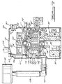
- Figure 1 is a section view of a hermetic scroll-type compressor in accordance with the present invention, the section being taken along an axially extending radial plane;
- Figure 2 is a fragmentary section view of the compressor of Figure 1 showing the oil return and injection arrangement;
- Figure 3 is a section view of the main bearing housing of the compressor shown in Figure I, the section being taken along line 3-3 thereof;
- Figure 4 is a perspective view of the discharge baffle incorporated in the compressor of Figure 1;
- Figure 5 is a section view of the non-orbiting scroll member forming a part of the compressor of Figure 1, the section being taken along line 5-5 of Figure 2;
- Figure 6 is a schematic view illustrating the refrigeration circuit incorporating the compressor of Figure 1;
- Figure 7 is a section view similar to that of Figure 2 but showing a hermetic scroll-type compressor specifically adapted for use as an air compressor all in accordance with the present invention;
- Figure 8 is an enlarged fragmentary view of the removable oil return fitting incorporated in the compressor of Figure 7; and
- Figure 9 is a schematic view similar to that of Figure 6 but showing a fluid circuit incorporating the air compressor of Figure 7.
-
- Referring now to the drawings and more specifically to Figure 1, there is shown a hermetic compressor of the scroll-type indicated generally at 10 in accordance with the present invention.
Compressor 10 includes anouter shell 12 within which is disposed a compressor assembly including an orbitingscroll member 14 having anend plate 16 from which a spiral wrap 18 extends, anon-orbiting scroll member 20 having anend plate 22 from which aspiral wrap 24 extends and a main bearinghousing 26 supportingly secured toouter shell 12. Main bearinghousing 26 supports orbitingscroll member 14 andnon-orbiting scroll member 20 is axially movably secured thereto withrespective wraps 18 and 24 positioned in meshing engagement such that as orbitingscroll member 14 orbits, the wraps will define moving fluid pockets that decrease in size as they move toward the center of the scroll members. - A
driving motor 28 is also provided in the lower portion ofshell 12 including astator 30 supported byshell 12 and arotor 32 secured to and drivingly connected to driveshaft 34.Drive shaft 34 is drivingly connected to orbitingscroll member 14 viaeccentric pin 36 and drive bushing 38 and is rotatably supported by upper bearinghousing 26 and a lower bearinghousing 40 which is also secured toshell 12. The lower end ofdrive shaft 34 extends into an oil sump 42 provided in the bottom ofshell 12. A reverse rotation prevention and lowercounterweight shield assembly 44 is also supported ondrive shaft 34 between lower bearing 40 andmotor assembly 28 and serves to restrict reverse rotation of the compressor on shut down as well as to restrict flow of oil to the area around the lower end of the rotor. In order to prevent orbitingscroll member 14 from rotating relative tonon-orbiting scroll member 20, an Oldhamcoupling 45 is provided being supported on main bearinghousing 26 and interconnecting with both orbitingscroll member 14 and non-orbitingscroll member 20. - In order to supply lubricant from oil sump 42 to the bearings and thrust surfaces, an oil pump is provided in the lower end of
drive shaft 34 which serves to direct oil axially upwardly through an eccentric axially extendingpassage 43 indrive shaft 34. Radial passages may be provided to supply lubricant to the main bearing and/or lower bearing and a portion of the oil will be discharged from the top ofeccentric pin 36 to lubricate the interface with drive bushing 38 and the interface between drive bushing 38 and orbitingscroll member 14. - A partition or
muffler plate 46 is also provided extending across the interior ofshell 12 and is sealingly secured thereto around its periphery. Mufflerplate 46 serves to divide the interior ofshell 12 into alower suction chamber 48 and anupper discharge chamber 50. - In operation, suction gas will be drawn into
suction chamber 48 ofcompressor 10 through suction inlet 52 and into the moving fluid pockets defined byscroll wraps 18 and 24 andend plates scroll member 14 orbits with respect tonon-orbiting scroll member 20, the fluid pockets will move inwardly decreasing in size and thereby compressing the fluid. The compressed fluid will be discharged intodischarge chamber 50 throughdischarge port 54 andpassage 56 provided innon-orbiting scroll member 20 anddischarge fitting assembly 58 secured tomuffler plate 46. The compressed fluid then exitscompressor 10 throughdischarge outlet 59. In order to maintain axially movablenon-orbiting scroll member 20 in axial sealing engagement with orbitingscroll member 14, apressure biasing chamber 60 is provided in the upper surface ofnon-orbiting scroll member 20. A floatingseal 62 is positioned withinchamber 60 and cooperates withmuffler plate 46 to prevent leakage of discharge gas flowing intodischarge chamber 50 fromdischarge port 54.Biasing chamber 60 is pressurized by fluid at intermediate pressure supplied from the fluid pockets under compression via passages (not shown) innon-orbiting scroll 20. - With the exception of discharge fitting 58,
compressor 10 as thus far described is similar to and incorporates features described in greater detail in assignee's patents numbers 4,877,382; 5,156,539; 5,102,316; 5,320,506; and 5,320,507 the disclosures of which are hereby incorporated by reference. - As noted above,
compressor 10 is specifically adapted for use with helium as a refrigerant. Because of the nature of helium, the compression of same in a refrigeration compressor results in the generation of significantly higher temperatures. In order to prevent these temperatures from becoming excessive, it is necessary to circulate substantially greater quantities of oil to the various components than typically is necessary when other more common refrigerants are utilized and to supply oil to the compression chambers as well. In addition to the need for the circulation of large quantities of oil, it is also very important that substantially all oil be removed from the compressed helium before it is supplied to the refrigeration or cryogenic system. - In order to accommodate these special requirements for use of helium as a refrigerant, the compressor of the present intention incorporates a generally radially extending
passage 64 in the end plate of orbitingscroll member 14.Passage 64 at its inner end opens into the chamber defined byhub 66 provided on orbitingscroll member 14 in which bushing 38 andeccentric pin 36 are disposed. The outer end ofpassage 64 is plugged and an axially extending passage 68 extends upwardly therefrom and opens into the flow of suction gas entering the compression pockets of the compressor.Passages 64 and 68 thus serve to direct a portion of the oil being thrown out of the top ofeccentric pin 36 to the suction gas flowing into the compression pockets. - In addition to the supply of oil to the suction
gas entering compressor 10, externally supplied oil is also injected into the fluid pockets during compression thereof. In order to accomplish this and as best seen with reference to Figures 2 and 5,end plate 22 ofnon-orbiting scroll member 20 is provided with a pair of generally chordally extendingpassages axial passages 74 and 76 opening into a pair of diametrically opposed fluid pockets which pockets are undergoing compression and hence at a pressure between suction and discharge. The outer ends ofpassages single passage 78 which opens outwardly through a sidewall of theend plate 22 of non-orbiting scroll 20. Afitting 80 is secured to the sidewall ofend plate 22 and defines a passage 82 leading from an oil inlet fitting 84 secured toouter shell 12 topassage 78. In order to accommodate axial movement ofnon-orbiting scroll member 20, fitting 80 is formed in two pieces withlower portion 86 being slidably telescopically received within the lower end ofupper portion 88. Suitable sealing means such as an O-ring will preferably be provided between upper andlower portions tubular member 90 serves to sealingly interconnect oil inlet fitting 84 withlower portion 86 of fitting 80. - In addition to the above, main bearing housing is provided with a plurality of generally radially extending
passages 92 which serve to direct oil accumulating inrecess 94 outwardly to Oldhamcoupling 45. As best seen with reference to Figure 3, there will preferably be four such radially extendingpassages 92 positioned in substantially 90° spaced relationship to each other. - Discharge fitting 58 includes an
upper tubular member 96 having a relatively large diameter threaded bore 98 opening inwardly from the lower end thereof and a depending locatingflange portion 100 which is received within anopening 102 provided inmuffler plate 46. A threadedflanged retainer 104 is received within bore 98 and serves to sealingly secure discharge fitting 58 tomuffler plate 46 and to define a flowpath for discharge gas fromdischarge passage 56 intodischarge chamber 50. - Discharge fitting 58 supports an
oil separator plate 106 secured to the upper end thereof in overlying relationship tooutlet openings 108.Oil separator plate 106 extends radially outwardly from fitting 58 and includes a plurality of radially spaced annular dependingflange portions 110 that serve to provide a tortuous flowpath for the discharge gas and thereby aid in separation of entrained oil. - Oil separated from the discharge gas by
separator plate 106 will accumulate in the lower portion ofdischarge chamber 50. In order to recirculate this oil, an oil outlet fitting 112 is provided being secured to shell 12 so as to open into a lower portion ofdischarge chamber 50 which defines an upper oil sump. Oil from outlet fitting 112 is supplied to oil inlet fitting 84 as described in greater detail below. - In order to prevent excessive accumulation of oil in
discharge chamber 50, a lubricant leveloil return assembly 114 is provided which operates to return excessive oil to lower sump 42 throughmuffler plate 46.Oil return assembly 114 includes a through fitting 116 sealingly secured to and extending throughmuffler plate 46 adjacent an outer peripheral edge thereof from which atube 118 extends to discharge fitting 58. Return fitting 116 defines apassage 128 extending therethrough which opens into the lowerpressure suction chamber 48 via opening 130. If desired, a suitable filter may be provided withinpassage 128 to prevent any particles from being returned to the lower sump. Discharge fitting 58 includes apassage 120 extending axially downward from the upper end thereof and communicating at its lower end with a radially inwardly extendingpassage 122 via a restrictedportion 124. The upper end ofpassage 120 is sealed off with asuitable plug 123.Tube 118 communicates with axially extendingpassage 120 via a secondradially extending passage 126 located aboveradial passage 122. - As the oil level in discharge chamber rises, oil will flow into
passage 122. Should the oil level rise above the lower edge ofrestrictor 124, oil will begin to flow throughrestrictor 124 intopassage 120 and thence topassage 126,tube 118 through fitting 116 and be returned to the lower sump 42. It should be noted that becausechamber 50 is at a pressure (discharge) greater than that of the pressure inchamber 48, oil will be forced throughpassage 122,restrictor 124, etc and hence returned to lower sump 42 so long as thelevel 127 indischarge chamber 50 remains above the lower edge ofrestrictor 124. However, restrictor 124 will operate to limit the flow of compressed gas intosuction chamber 48 during periods in whichoil level 127 is below the lower edge ofrestrictor 124. It should also be noted that, if desired, plug 123 could be omitted thereby leavingpassage 120 in open communication with the compressed gas indischarge chamber 50. In such case, it is necessary thatrestrictor 124 be located downstream ofpassage 120, i.e., inpassage 126,tube 118 or throughfitting 116. It should be noted thatpassage 120 will preferably be located substantially coaxial with the axial center ofcompressor 10. This will ensure that opening ofrestrictor 124 and/orpassage 126 intopassage 120 is in close proximity to the center axis 129 of the compressor and will greatly reduce the effect of tilting ofcompressor 10 on the level of oil retained in thedischarge chamber 50. - In order to reduce the amount of oil entrained in the discharge gas that is carried over into
discharge outlet 59 and also to resist large quantities of oil being expelled therethrough shouldcompressor 10 be tilted so as to raise the oil level above the lower portion ofdischarge outlet 59, abaffle member 132 is secured to shell 12 in overlying relationship to the inner end ofdischarge outlet 59. As shown in Figure 4,baffle member 132 may be in the form of a box having anopening 134 on the top sidewall thereof and anopen end 136 which is sealingly secured to the inner surface ofshell 12. Alternately,baffle member 132 may be cylindrical in shape with one end closed andopening 134 being oriented so as to face upwardly away from the upper surface of the lubricant indischarge chamber 50. - Referring now to Figure 6,
compressor 10 is shown incorporated in a refrigeration or cryogenic circuit specifically designed for use of helium as a refrigerant. As shown therein, compressed helium flows fromcompressor 10 vialine 138 to aheat exchanger 140 which serves to separate oil therefrom. Fromheat exchanger 140, the compressed helium is routed serially throughadditional oil separators 142 to ensure substantially complete removal of entrained oil therefrom after which it is directed to acondenser 144 and then to additional system components (not shown) such as an evaporator and then returned tocompressor 10 vialine 141. Oil collected indischarge chamber 50 is directed fromoil outlet 112 to aheat exchanger 146 vialine 148 for cooling. Oil fromheat exchanger 146 together with separated oil fromheat exchanger 140 andoil separators 142 is then supplied to oil inlet fitting 84 vialine 143 from which it is directed to the respective fluid pockets under compression. Because this oil is at substantially discharge pressure, oil will easily be caused to flow into the desired fluid pockets under compression which will be at a pressure above suction pressure but below discharge pressure. As shown,suitable check valves 150 are included at bothdischarge outlet 59 andoil outlet 112 to prevent undesired reverse flow of fluids. Additionally, lubricant separated inheat exchanger 140 as well aslubricant separators 142 will also be supplied to oil inlet fitting 84 vialine 145 for injection into the moving fluid pockets. It should be noted that it is desirable that the pressure of the lubricant being returned to oil inlet fitting 84 from the various sources be at substantially the same pressure. Accordingly, suitablysized restrictors 147 are provided at the outlets of each of theoil separators 142 andheat exchangers - As will now be appreciated,
compressor 10 is designed to provide a high volume of oil flow to the compressor to both lubricate the various portions thereof as well as to ensure adequate cooling of the compressor. Additionally,compressor 10 includes an integral oil separator to aid in removal of the oil from the compressed refrigerant as well as to ensure an adequate supply of oil for injection into the compressor. Additionally, the provision for oil injection into the suction inlet provides insurance that the level of oil in the discharge chamber will be maintained whereas the overflow arrangement prevents this level from becoming excessively high. - Referring now to Figure 7, a second embodiment of a compressor in accordance with the subject invention is disclosed which compressor is specifically adapted for use as an air compressor. Except as noted below,
compressor 152 is substantially identical tocompressor 10 including without limitation both the oil injection into the fluid pockets under compression, the injection of oil into the suction gas flowing to the compression pockets and the internal oil separator incorporated incompressor 10 as shown in Figure 1. Accordingly, corresponding portions thereof have been indicated by the same reference numbers primed. - In place of the suction inlet 52 incorporated in
compressor 10,compressor 152 includes aninlet assembly 154 which includesconduit 156 secured to the outer shell 12' which is adapted to receive a threaded connection forsuction inlet conduit 158. Asuction filter assembly 160, which may also include a muffler if desired, is secured to the other end ofconduit 158 and serves to filter out particulate matter that could result in excessive wear as well as to muffle possible noise of the air being drawn intocompressor 152. - Additionally, discharge fitting 162 of
compressor 152 includes a restrictedopening 164 at its inner end.Restricted opening 164 serves to restrict the flow of compressed air out of discharge chamber 50' which is particuiarly important during periods of compressor operation in which the back pressure loading is at zero or very low as this build up of discharge pressure in chamber 50' acts together with the intermediate pressure in biasing chamber 60' to bias the non-orbiting scroll member 20' axially into sealing engagement with orbiting scroll member 14'. Additionally, in order to ensure sufficient biasing force on non-orbiting scroll member 20' to begin compressing air on compressor start up as well as to ensure proper initial sealing between seal 62' and muffler plate 46', a plurality of springs are provided in biasing chamber 60' acting between a lower surface of seal 62' and the bottom surface of biasing chamber 60'. - It should be noted that the inclusion of
restrictor 164 in discharge fitting 162 will not appreciably reduce system efficiency because during normal operation, the density of the compressed air flowing therethrough will be substantially greater than at low pressure operation. - In addition to the above,
compressor 152 incorporates a modified arrangement for preventing accumulation of excessive oil in the discharge chamber. As best seen with reference to Figures 7 and 8,compressor 152 includes anelongated member 166 extending axially inwardly through asuitable fitting 168 provided on the top portion of outer shell 12' and having alower end 170 threadedly received in a threadedopening 172 provided in muffler plate 46'. In order to prevent leakage through fitting 168 from discharge chamber 50', elongated member is provided with ashoulder 174 adjacent the upper end against which a suitable O-ring 176 is seated. Similarly, in order to prevent leakage throughopening 172 in muffler plate 46', asecond shoulder 178 is provided against which O-ring 180 is seated. -
Elongated member 166 comprises anupper member 182 having anaxially extending bore 184 provided therein and a plurality of circumferentially spaced radial bores 186 opening intobore 184 adjacent the upper end thereof. Alower member 188 is also provided having reduceddiameter portion 190 provided at the upper end thereof which is sized to be threadedly received inbore 184 ofupper member 182. Acentral bore 192 extends axially from the upper end oflower member 188 forming a continuation ofbore 184 and terminates adjacent the lower end where arestricted opening 194 is provided opening outwardly from the bottom oflower member 188. Asuitable filter 196 is provided fitted in the upper end oflower member 188 and serves to filter any debris from oil being returned to the lower sump.Elongated member 166 is designed for easy removal and disassembly so as to enable periodic cleaning and/or replacement offilter 196. It should be noted that the distance fromshoulder 178 topassages 186 will determine the oil level within discharge chamber 50'. Further, when the oil level is belowpassages 186, the restrictedopening 194 will operate to limit the leakage of compressed air to the suction chamber. -
Compressor 152 also incorporates apressure relief valve 198 secured to outer shell 12' which is operative to vent discharge chamber 50' to atmosphere in response to an excessive pressure therein. - In addition to the above,
compressor 152 includes atemperature sensor 228 extending into the oil sump provided in the lower portion of the discharge chamber 50'.Temperature sensor 228 is interconnected with the power supply to motor 28' and operates to deenergize same in response to an excessive temperature in the discharge chamber. It should be noted that whiletemperature sensor 228 is positioned so as to be immersed in the oil and hence will be primarily responsive to excessive oil temperature, it will also respond to excessive discharge gas temperature in the event the oil level drops belowsensor 228. - Referring now to Figure 9, a schematic of a compressor air and oil circulation circuit is shown incorporating compressor 152.,
Discharge outlet 162 ofcompressor 152 extends vialine 200 to an oil separator 202 which operates to remove entrained oil from the compressed air. From oil separator 202, the compressed air is directed to a suitable storage tank (not shown) via line 204. A blow downvalve 206 and associatedsilencer 208 is provided along line 204 and before a check valve 210 and serves to release any residual pressure in discharge chamber 50', oil separator 202 andlines 200 and 204 whencompressor 152 is shut down. This pressure is vented to ensure thatcompressor 152 will not be required to start against a heavy pressure load that may exist. Preferably, blow downvalve 206 will be a suitable solenoid actuated valve and check valve 210 will ensure that the tank or reservoir pressure is not vented. - Oil return outlet 112' is connected to a suitable oil cooler 212 via
line 214. Acheck valve 216 is provided inline 214 adjacent outlet 112'. In order to prevent excessive cooling of the oil, asuitable bypass line 218 and associatedvalve 220 is provided which may operate to direct a portion or all of the oil directly to returnline 222 thereby bypassingheat exchanger 212.Return line 222 extends back to oil injection inlet fitting 84' provided oncompressor 152. Additionally, oil separated by oil separator 202 is also supplied to oil injection fitting 84' vialine 224. In order to prevent debris entrained within the oil from being injected into the fluid pockets under compression, filters 226 are provided in bothlines - While it will be apparent that the preferred embodiments of the invention disclosed are well calculated to provide the advantages and features above stated, it will be appreciated that the invention is susceptible to modification, variation and change without departing from the proper scope or fair meaning of the subjoined claims.
Claims (5)
- A scroll-type compressor comprising:an enclosed shell (12);a first scroll member (14) disposed within said shell and including a first end plate (16) having a first spiral wrap (18) thereon;a second scroll member (20) disposed within said shell and including a second end plate (22) having a second spiral wrap (24) thereon;said scroll members being supported for orbital movement relative to one another;said first and second spiral wraps (18,24) being intermeshed so as to define moving fluid pockets which decrease in size in response to said orbital movement to compress a gas in said shell;a lubricant sump (42) disposed in said shell;a suction inlet (52;154) through said shell for supplying suction gas to said scroll-members;a lubricant delivery system for delivering lubricant from said. sump to said fluid pockets;a first lubricant separator (106) disposed within said shell, said lubricant separator being operative to separate lubricant from said compressed gas and return said separated lubricant to said sump; anda second lubricant separator (132) disposed within said shell, said second lubricant separator being downstream from said first lubricant separator and operative to separate lubricant from said compressed gas and return said lubricant to said sump.
- A scroll-type compressor as set forth in claim 1 further comprising a filter (196) within said shell for filtering said lubricant.
- A scroll-type compressor as set forth in claim 1 or 2, wherein said lubricant delivery system further operates to inject lubricant into said suction gas.
- A scroll-type compressor as set forth in claim 3 further comprising a second lubricant sump (50;50'), said lubricant injected into said suction gas being supplied from said second sump to thereby replenish the first mentioned said lubricant sump.
- A scroll-type compressor as set forth in claim 1 further comprising a temperature sensor (228) in said lubricant sump, said temperature sensor being operative to de-energize said compressor in response to an excessive temperature in said lubricant sump.
Applications Claiming Priority (4)
| Application Number | Priority Date | Filing Date | Title |
|---|---|---|---|
| US08/693,594 US6017205A (en) | 1996-08-02 | 1996-08-02 | Scroll compressor |
| US693594 | 1996-08-02 | ||
| EP97305785A EP0822335B1 (en) | 1996-08-02 | 1997-07-31 | Scroll compressor |
| EP03010102A EP1331397B1 (en) | 1996-08-02 | 1997-07-31 | Scroll compressor |
Related Parent Applications (1)
| Application Number | Title | Priority Date | Filing Date |
|---|---|---|---|
| EP03010102A Division EP1331397B1 (en) | 1996-08-02 | 1997-07-31 | Scroll compressor |
Publications (2)
| Publication Number | Publication Date |
|---|---|
| EP1477680A2 true EP1477680A2 (en) | 2004-11-17 |
| EP1477680A3 EP1477680A3 (en) | 2005-12-07 |
Family
ID=24785309
Family Applications (4)
| Application Number | Title | Priority Date | Filing Date |
|---|---|---|---|
| EP04018132A Withdrawn EP1477680A3 (en) | 1996-08-02 | 1997-07-31 | Scroll compressor |
| EP04016535A Withdrawn EP1475541A3 (en) | 1996-08-02 | 1997-07-31 | Scroll compressor |
| EP97305785A Expired - Lifetime EP0822335B1 (en) | 1996-08-02 | 1997-07-31 | Scroll compressor |
| EP03010102A Expired - Lifetime EP1331397B1 (en) | 1996-08-02 | 1997-07-31 | Scroll compressor |
Family Applications After (3)
| Application Number | Title | Priority Date | Filing Date |
|---|---|---|---|
| EP04016535A Withdrawn EP1475541A3 (en) | 1996-08-02 | 1997-07-31 | Scroll compressor |
| EP97305785A Expired - Lifetime EP0822335B1 (en) | 1996-08-02 | 1997-07-31 | Scroll compressor |
| EP03010102A Expired - Lifetime EP1331397B1 (en) | 1996-08-02 | 1997-07-31 | Scroll compressor |
Country Status (4)
| Country | Link |
|---|---|
| US (1) | US6017205A (en) |
| EP (4) | EP1477680A3 (en) |
| JP (1) | JPH1077979A (en) |
| DE (2) | DE69732441T2 (en) |
Cited By (1)
| Publication number | Priority date | Publication date | Assignee | Title |
|---|---|---|---|---|
| CN102678573A (en) * | 2011-03-11 | 2012-09-19 | 上海日立电器有限公司 | Exhausting structure of horizontal rolling rotor compressor |
Families Citing this family (86)
| Publication number | Priority date | Publication date | Assignee | Title |
|---|---|---|---|---|
| JP4153131B2 (en) * | 1999-09-14 | 2008-09-17 | サンデン株式会社 | Electric compressor |
| US6257840B1 (en) * | 1999-11-08 | 2001-07-10 | Copeland Corporation | Scroll compressor for natural gas |
| US6280146B1 (en) * | 2000-02-24 | 2001-08-28 | Scroll Technologies | Sealed compressor using hot oil to actuate protector switch |
| US6217302B1 (en) * | 2000-02-24 | 2001-04-17 | Scroll Technologies | Floating seal bias for reverse fun protection in scroll compressor |
| TWI237682B (en) * | 2000-07-07 | 2005-08-11 | Sanyo Electric Co | Freezing apparatus |
| US6374621B1 (en) | 2000-08-24 | 2002-04-23 | Cincinnati Sub-Zero Products, Inc. | Refrigeration system with a scroll compressor |
| US6848889B2 (en) | 2000-10-17 | 2005-02-01 | Scroll Technologies | Oil utilized as motor protector trip for scroll compressor |
| KR20030070136A (en) * | 2001-01-29 | 2003-08-27 | 마쯔시다덴기산교 가부시키가이샤 | Scroll compressor |
| CN102200356B (en) * | 2001-02-23 | 2014-03-26 | 布鲁克斯自动化公司 | Ultra-low temperature closed-loop recirculating gas chilling system |
| US6464480B2 (en) | 2001-03-16 | 2002-10-15 | Scroll Technologies | Oil spout for scroll compressor |
| AU2002305423A1 (en) * | 2001-05-07 | 2002-11-18 | Battelle Memorial Institute | Heat energy utilization system |
| US6572352B2 (en) * | 2001-10-16 | 2003-06-03 | Copeland Corporation | Two-piece powdered metal suction fitting |
| US6533562B1 (en) * | 2001-10-16 | 2003-03-18 | Scroll Technologies | Two-stage oil injection into scroll compressors |
| KR100924895B1 (en) * | 2002-05-24 | 2009-11-02 | 파나소닉 주식회사 | Scroll compressor |
| AU2003276891A1 (en) * | 2002-09-18 | 2004-04-08 | Igc-Polycold Systems, Inc. | Very low temperature refrigeration system having a scroll compressor with liquid injection |
| JP2004270614A (en) * | 2003-03-11 | 2004-09-30 | Sanden Corp | Electric compressor |
| JP4219262B2 (en) * | 2003-12-10 | 2009-02-04 | サンデン株式会社 | Compressor |
| JP2005171859A (en) * | 2003-12-10 | 2005-06-30 | Sanden Corp | Compressor |
| JP4286175B2 (en) * | 2004-04-13 | 2009-06-24 | サンデン株式会社 | Compressor |
| JP2005337142A (en) * | 2004-05-27 | 2005-12-08 | Sanden Corp | Compressor |
| JP2005351112A (en) * | 2004-06-08 | 2005-12-22 | Sanden Corp | Scroll compressor |
| JP2006097495A (en) * | 2004-09-28 | 2006-04-13 | Sanden Corp | Compressor |
| KR100679886B1 (en) * | 2004-10-06 | 2007-02-08 | 엘지전자 주식회사 | A orbiting vane with lubricating oil supply function using a orbiting vane compressor |
| KR100679883B1 (en) * | 2004-10-06 | 2007-02-08 | 엘지전자 주식회사 | A hermetic type orbiter compressor |
| US7186099B2 (en) * | 2005-01-28 | 2007-03-06 | Emerson Climate Technologies, Inc. | Inclined scroll machine having a special oil sump |
| JP2006207494A (en) * | 2005-01-28 | 2006-08-10 | Sanden Corp | Compressor |
| KR100696127B1 (en) * | 2005-03-30 | 2007-03-22 | 엘지전자 주식회사 | Oil suppling structure of scroll compressor |
| US7862312B2 (en) * | 2005-05-02 | 2011-01-04 | Tecumseh Products Company | Suction baffle for scroll compressors |
| US7815423B2 (en) * | 2005-07-29 | 2010-10-19 | Emerson Climate Technologies, Inc. | Compressor with fluid injection system |
| US7566210B2 (en) * | 2005-10-20 | 2009-07-28 | Emerson Climate Technologies, Inc. | Horizontal scroll compressor |
| US7674099B2 (en) * | 2006-04-28 | 2010-03-09 | Sumitomo Heavy Industries, Ltd. | Compressor with oil bypass |
| US8187370B2 (en) | 2006-07-13 | 2012-05-29 | Shi-Apd Cryogenics, Inc. | Horizontal bulk oil separator |
| JP4939884B2 (en) * | 2006-09-28 | 2012-05-30 | 日立アプライアンス株式会社 | Fluid compressor |
| US9404499B2 (en) * | 2006-12-01 | 2016-08-02 | Emerson Climate Technologies, Inc. | Dual chamber discharge muffler |
| US8057194B2 (en) * | 2006-12-01 | 2011-11-15 | Emerson Climate Technologies, Inc. | Compressor with discharge muffler attachment using a spacer |
| CN101205907B (en) * | 2006-12-20 | 2011-06-08 | 乐金电子(天津)电器有限公司 | Scroll compressor and assembling method thereof |
| US20080184733A1 (en) * | 2007-02-05 | 2008-08-07 | Tecumseh Products Company | Scroll compressor with refrigerant injection system |
| US20090175739A1 (en) * | 2008-01-07 | 2009-07-09 | Kanwal Bhatia | Dual drive compressor |
| CA2747867C (en) * | 2008-06-16 | 2013-09-10 | Tecumseh Products Company | Baffle member for scroll compressors |
| CA2671109C (en) * | 2008-07-08 | 2012-10-23 | Tecumseh Products Company | Scroll compressor utilizing liquid or vapor injection |
| US8037712B2 (en) * | 2008-10-28 | 2011-10-18 | Lg Electronics Inc. | Hermetic compressor and refrigeration cycle having the same |
| CN101769257B (en) * | 2008-12-30 | 2012-06-27 | 上海日立电器有限公司 | Gas-oil separation baffle for air condition compressor |
| US7988433B2 (en) | 2009-04-07 | 2011-08-02 | Emerson Climate Technologies, Inc. | Compressor having capacity modulation assembly |
| US8590324B2 (en) * | 2009-05-15 | 2013-11-26 | Emerson Climate Technologies, Inc. | Compressor and oil-cooling system |
| US8978400B2 (en) * | 2009-11-09 | 2015-03-17 | Sumitomo (Shi) Cryogenics Of America Inc. | Air cooled helium compressor |
| US8517703B2 (en) * | 2010-02-23 | 2013-08-27 | Emerson Climate Technologies, Inc. | Compressor including valve assembly |
| US9157439B2 (en) | 2010-03-30 | 2015-10-13 | Emerson Climate Technologies, Inc. | Universal oil fitting |
| US8944790B2 (en) | 2010-10-20 | 2015-02-03 | Thermo King Corporation | Compressor with cyclone and internal oil reservoir |
| EP2589898B1 (en) * | 2011-11-04 | 2018-01-24 | Emerson Climate Technologies GmbH | Oil management system for a compressor |
| CN103541904B (en) * | 2012-07-11 | 2016-08-24 | 珠海格力节能环保制冷技术研究中心有限公司 | Keep off oil part and there is the compressor of this gear oil part |
| CN104619987B (en) | 2012-09-13 | 2018-01-12 | 艾默生环境优化技术有限公司 | Compressor assembly with guiding sucting |
| US9249802B2 (en) | 2012-11-15 | 2016-02-02 | Emerson Climate Technologies, Inc. | Compressor |
| US9651043B2 (en) | 2012-11-15 | 2017-05-16 | Emerson Climate Technologies, Inc. | Compressor valve system and assembly |
| US9181939B2 (en) | 2012-11-16 | 2015-11-10 | Emerson Climate Technologies, Inc. | Compressor crankcase heating control systems and methods |
| US9435340B2 (en) | 2012-11-30 | 2016-09-06 | Emerson Climate Technologies, Inc. | Scroll compressor with variable volume ratio port in orbiting scroll |
| JP6074620B2 (en) * | 2013-03-22 | 2017-02-08 | パナソニックIpマネジメント株式会社 | Compressor |
| US9989057B2 (en) | 2014-06-03 | 2018-06-05 | Emerson Climate Technologies, Inc. | Variable volume ratio scroll compressor |
| DE102014113949B4 (en) | 2014-09-26 | 2019-09-19 | Technische Universität Dresden | Device for changing the pressure of a working substance |
| FR3031549B1 (en) * | 2015-01-13 | 2017-02-10 | Danfoss Commercial Compressors | SPIRAL COMPRESSOR HAVING TWO OIL PANELS |
| US10302340B2 (en) | 2015-03-11 | 2019-05-28 | Emerson Climate Technologies, Inc. | Compressor having lubricant management system for bearing life |
| US9790940B2 (en) | 2015-03-19 | 2017-10-17 | Emerson Climate Technologies, Inc. | Variable volume ratio compressor |
| US10378540B2 (en) | 2015-07-01 | 2019-08-13 | Emerson Climate Technologies, Inc. | Compressor with thermally-responsive modulation system |
| CN207377799U (en) | 2015-10-29 | 2018-05-18 | 艾默生环境优化技术有限公司 | Compressor |
| US10436201B2 (en) * | 2016-06-21 | 2019-10-08 | Danfoss LLC | Scroll compressor provided with a lubrication system |
| US10890186B2 (en) | 2016-09-08 | 2021-01-12 | Emerson Climate Technologies, Inc. | Compressor |
| US10801495B2 (en) | 2016-09-08 | 2020-10-13 | Emerson Climate Technologies, Inc. | Oil flow through the bearings of a scroll compressor |
| US10753352B2 (en) | 2017-02-07 | 2020-08-25 | Emerson Climate Technologies, Inc. | Compressor discharge valve assembly |
| US11022119B2 (en) | 2017-10-03 | 2021-06-01 | Emerson Climate Technologies, Inc. | Variable volume ratio compressor |
| US10962008B2 (en) | 2017-12-15 | 2021-03-30 | Emerson Climate Technologies, Inc. | Variable volume ratio compressor |
| CN108278206A (en) * | 2018-03-22 | 2018-07-13 | 宁波汇峰聚威科技股份有限公司 | A kind of variable-flow screw compressor |
| US10995753B2 (en) | 2018-05-17 | 2021-05-04 | Emerson Climate Technologies, Inc. | Compressor having capacity modulation assembly |
| CN110552886B (en) * | 2018-05-31 | 2024-06-07 | 谷轮环境科技(苏州)有限公司 | Compressor with a compressor body having a rotor with a rotor shaft |
| DE102018208970A1 (en) * | 2018-06-06 | 2019-12-12 | Fraunhofer-Gesellschaft zur Förderung der angewandten Forschung e.V. | Compressor, heat pump or air conditioning or cold machine and method of compacting |
| CN208651145U (en) * | 2018-06-22 | 2019-03-26 | 艾默生环境优化技术(苏州)有限公司 | Scroll compressor having a plurality of scroll members |
| CN109139460A (en) * | 2018-07-25 | 2019-01-04 | 南京奥特佳新能源科技有限公司 | A kind of screw compressor with gas oil separation structure |
| US11236748B2 (en) | 2019-03-29 | 2022-02-01 | Emerson Climate Technologies, Inc. | Compressor having directed suction |
| WO2020202515A1 (en) * | 2019-04-03 | 2020-10-08 | 日立ジョンソンコントロールズ空調株式会社 | Compressor and air conditioner |
| US11767838B2 (en) | 2019-06-14 | 2023-09-26 | Copeland Lp | Compressor having suction fitting |
| CN110966200B (en) * | 2019-11-25 | 2022-02-25 | 珠海格力节能环保制冷技术研究中心有限公司 | Compressor and air conditioner with same |
| KR102381244B1 (en) * | 2020-06-17 | 2022-03-31 | 엘지전자 주식회사 | Scroll compressor |
| US11248605B1 (en) | 2020-07-28 | 2022-02-15 | Emerson Climate Technologies, Inc. | Compressor having shell fitting |
| US11619228B2 (en) | 2021-01-27 | 2023-04-04 | Emerson Climate Technologies, Inc. | Compressor having directed suction |
| US11655813B2 (en) | 2021-07-29 | 2023-05-23 | Emerson Climate Technologies, Inc. | Compressor modulation system with multi-way valve |
| CN114183348B (en) * | 2021-12-17 | 2022-08-26 | 珠海格力电器股份有限公司 | Quiet dish subassembly reaches scroll compressor including it |
| US11846287B1 (en) | 2022-08-11 | 2023-12-19 | Copeland Lp | Scroll compressor with center hub |
| US11965507B1 (en) | 2022-12-15 | 2024-04-23 | Copeland Lp | Compressor and valve assembly |
Family Cites Families (53)
| Publication number | Priority date | Publication date | Assignee | Title |
|---|---|---|---|---|
| JPS55107093A (en) * | 1979-02-13 | 1980-08-16 | Hitachi Ltd | Enclosed type scroll compressor |
| JPS56165788A (en) * | 1980-05-23 | 1981-12-19 | Hitachi Ltd | Enclosed scroll compressor |
| JPS593182A (en) * | 1982-06-30 | 1984-01-09 | Hitachi Ltd | Closed-type electric motor-driven compressor |
| JPS5932691A (en) * | 1983-06-06 | 1984-02-22 | Mitsubishi Electric Corp | Scroll compressor |
| JPS6073080A (en) * | 1983-09-30 | 1985-04-25 | Toshiba Corp | Scroll type compressor |
| JPS60187789A (en) * | 1984-03-05 | 1985-09-25 | Mitsubishi Electric Corp | Scroll compressor |
| JPS60192894A (en) * | 1984-03-13 | 1985-10-01 | Mitsubishi Electric Corp | Scroll compressor |
| JPS6140483A (en) * | 1984-07-31 | 1986-02-26 | Toshiba Corp | Scroll type compressor |
| JPS61112795A (en) * | 1984-11-05 | 1986-05-30 | Hitachi Ltd | Sealed type scroll compressor |
| JPH0617676B2 (en) * | 1985-02-15 | 1994-03-09 | 株式会社日立製作所 | Helium scroll compressor |
| JPS61268896A (en) * | 1985-05-24 | 1986-11-28 | Toshiba Corp | Scroll type compression device |
| DE3521253A1 (en) * | 1985-06-13 | 1986-12-18 | Bock GmbH & Co Kältemaschinenfabrik, 7440 Nürtingen | Spiral compressor |
| JPS6275091A (en) * | 1985-09-30 | 1987-04-06 | Toshiba Corp | Scroll compressor |
| JPS62182492A (en) * | 1986-02-03 | 1987-08-10 | Matsushita Refrig Co | Scroll compressor |
| US5102316A (en) * | 1986-08-22 | 1992-04-07 | Copeland Corporation | Non-orbiting scroll mounting arrangements for a scroll machine |
| US5219281A (en) * | 1986-08-22 | 1993-06-15 | Copeland Corporation | Fluid compressor with liquid separating baffle overlying the inlet port |
| US4877382A (en) * | 1986-08-22 | 1989-10-31 | Copeland Corporation | Scroll-type machine with axially compliant mounting |
| JPH0633787B2 (en) * | 1987-07-27 | 1994-05-02 | 松下電器産業株式会社 | Scroll gas compressor |
| JPH01285689A (en) * | 1988-05-11 | 1989-11-16 | Daikin Ind Ltd | Oil separating device |
| JPH07111183B2 (en) * | 1988-09-28 | 1995-11-29 | ダイキン工業株式会社 | Scroll compressor |
| US4917582A (en) * | 1989-02-27 | 1990-04-17 | Carrier Corporation | Horizontal scroll compressor with oil pump |
| JP2782858B2 (en) * | 1989-10-31 | 1998-08-06 | 松下電器産業株式会社 | Scroll gas compressor |
| JP2606388B2 (en) * | 1989-11-02 | 1997-04-30 | 松下電器産業株式会社 | Scroll compressor |
| JP2647225B2 (en) * | 1990-03-20 | 1997-08-27 | 株式会社日立製作所 | Scroll compressor and refrigeration system for liquefaction of helium using the same |
| US5076067A (en) * | 1990-07-31 | 1991-12-31 | Copeland Corporation | Compressor with liquid injection |
| DE69103604T2 (en) * | 1990-10-01 | 1994-12-22 | Copeland Corp | Oldham's clutch for scroll compressors. |
| US5156539A (en) * | 1990-10-01 | 1992-10-20 | Copeland Corporation | Scroll machine with floating seal |
| US5141407A (en) * | 1990-10-01 | 1992-08-25 | Copeland Corporation | Scroll machine with overheating protection |
| US5320507A (en) * | 1991-10-17 | 1994-06-14 | Copeland Corporation | Scroll machine with reverse rotation protection |
| KR930008386A (en) * | 1991-10-30 | 1993-05-21 | 가나이 쯔또무 | Shallow compressors and air conditioners using it |
| JPH05133355A (en) * | 1991-11-08 | 1993-05-28 | Hitachi Ltd | Oil supply device for closed type scroll compressor |
| JP3038454B2 (en) * | 1991-11-08 | 2000-05-08 | 株式会社日立製作所 | Hermetic scroll compressor and oil supply device thereof |
| JPH05223074A (en) * | 1992-02-07 | 1993-08-31 | Zexel Corp | Oil circulating mechanism of scroll type compressor |
| US5256042A (en) * | 1992-02-20 | 1993-10-26 | Arthur D. Little, Inc. | Bearing and lubrication system for a scroll fluid device |
| JP3111602B2 (en) * | 1992-03-09 | 2000-11-27 | ダイキン工業株式会社 | Horizontal scroll compressor |
| JPH05340372A (en) * | 1992-06-10 | 1993-12-21 | Tokico Ltd | Oil cooled air compressor |
| JPH062682A (en) * | 1992-06-17 | 1994-01-11 | Zexel Corp | Scroll compressor |
| US5368446A (en) * | 1993-01-22 | 1994-11-29 | Copeland Corporation | Scroll compressor having high temperature control |
| JPH06294388A (en) * | 1993-04-09 | 1994-10-21 | Sanyo Electric Co Ltd | Scroll compressing device |
| JP3173267B2 (en) * | 1993-12-28 | 2001-06-04 | 松下電器産業株式会社 | Scroll compressor |
| US5421708A (en) * | 1994-02-16 | 1995-06-06 | Alliance Compressors Inc. | Oil separation and bearing lubrication in a high side co-rotating scroll compressor |
| JP3073387B2 (en) * | 1994-02-28 | 2000-08-07 | 三菱重工業株式会社 | Oil recovery device for compressor |
| US5452989A (en) * | 1994-04-15 | 1995-09-26 | American Standard Inc. | Reverse phase and high discharge temperature protection in a scroll compressor |
| US5564280A (en) * | 1994-06-06 | 1996-10-15 | Schilling; Ronald W. | Apparatus and method for refrigerant fluid leak prevention |
| JPH0828458A (en) * | 1994-07-12 | 1996-01-30 | Daikin Ind Ltd | Selfrotation preventing device in scroll-type fluid machine |
| JP3147676B2 (en) * | 1994-09-20 | 2001-03-19 | 株式会社日立製作所 | Scroll compressor |
| MY126636A (en) * | 1994-10-24 | 2006-10-31 | Hitachi Ltd | Scroll compressor |
| JPH08135581A (en) * | 1994-11-07 | 1996-05-28 | Hitachi Ltd | Scroll fluid machinery |
| US5593294A (en) * | 1995-03-03 | 1997-01-14 | Copeland Corporation | Scroll machine with reverse rotation protection |
| US5640854A (en) * | 1995-06-07 | 1997-06-24 | Copeland Corporation | Scroll machine having liquid injection controlled by internal valve |
| US5707210A (en) * | 1995-10-13 | 1998-01-13 | Copeland Corporation | Scroll machine with overheating protection |
| US5683236A (en) * | 1996-03-21 | 1997-11-04 | Alliance Compressors | Anti-reverse rotation valve for scroll compressor |
| US5667371A (en) * | 1996-04-08 | 1997-09-16 | Copeland Corporation | Scroll machine with muffler assembly |
-
1996
- 1996-08-02 US US08/693,594 patent/US6017205A/en not_active Expired - Lifetime
-
1997
- 1997-07-31 EP EP04018132A patent/EP1477680A3/en not_active Withdrawn
- 1997-07-31 EP EP04016535A patent/EP1475541A3/en not_active Withdrawn
- 1997-07-31 EP EP97305785A patent/EP0822335B1/en not_active Expired - Lifetime
- 1997-07-31 DE DE69732441T patent/DE69732441T2/en not_active Expired - Fee Related
- 1997-07-31 EP EP03010102A patent/EP1331397B1/en not_active Expired - Lifetime
- 1997-07-31 DE DE69725522T patent/DE69725522T2/en not_active Expired - Fee Related
- 1997-08-01 JP JP9220707A patent/JPH1077979A/en active Pending
Non-Patent Citations (1)
| Title |
|---|
| None * |
Cited By (2)
| Publication number | Priority date | Publication date | Assignee | Title |
|---|---|---|---|---|
| CN102678573A (en) * | 2011-03-11 | 2012-09-19 | 上海日立电器有限公司 | Exhausting structure of horizontal rolling rotor compressor |
| CN102678573B (en) * | 2011-03-11 | 2015-10-28 | 上海日立电器有限公司 | A kind of exhaust structure of horizontal type rolling rotor formula compressor |
Also Published As
| Publication number | Publication date |
|---|---|
| EP1331397A3 (en) | 2003-09-17 |
| US6017205A (en) | 2000-01-25 |
| EP1331397A2 (en) | 2003-07-30 |
| EP1477680A3 (en) | 2005-12-07 |
| EP0822335A2 (en) | 1998-02-04 |
| JPH1077979A (en) | 1998-03-24 |
| EP0822335A3 (en) | 1998-05-06 |
| DE69732441T2 (en) | 2006-01-05 |
| DE69725522D1 (en) | 2003-11-20 |
| DE69732441D1 (en) | 2005-03-10 |
| EP1331397B1 (en) | 2005-02-02 |
| EP0822335B1 (en) | 2003-10-15 |
| EP1475541A2 (en) | 2004-11-10 |
| DE69725522T2 (en) | 2004-08-12 |
| EP1475541A3 (en) | 2005-11-23 |
Similar Documents
| Publication | Publication Date | Title |
|---|---|---|
| EP1331397B1 (en) | Scroll compressor | |
| CN202065179U (en) | Compressor and oil cooling system | |
| AU759564B2 (en) | Scroll compressor for natural gas | |
| EP1496258B1 (en) | Hermetic compressors | |
| US4781542A (en) | Hermetically-sealed compressor with motor | |
| EP1696128B1 (en) | Scroll machine | |
| KR100654122B1 (en) | Scroll compressor | |
| KR970003257B1 (en) | Horizontal rotary compressor | |
| EP1182353A1 (en) | Scroll machine | |
| US6082495A (en) | Scroll compressor bearing lubrication | |
| JPS6139520B2 (en) | ||
| US5466136A (en) | Scroll compressor having a gas liquid separator | |
| EP1358408B1 (en) | Horizontal scroll compressor | |
| CN101900113B (en) | Compressor and oil-cooling system | |
| US6129531A (en) | Open drive scroll machine | |
| JP2002276578A (en) | Rotary type multi-stage compressor | |
| WO2014106233A1 (en) | Compressor control for reverse rotation failure | |
| CN114174680B (en) | Helium compressor system with unmodified scroll compressor | |
| JPH0742952B2 (en) | Lubrication type hermetic scroll compressor |
Legal Events
| Date | Code | Title | Description |
|---|---|---|---|
| PUAI | Public reference made under article 153(3) epc to a published international application that has entered the european phase |
Free format text: ORIGINAL CODE: 0009012 |
|
| AC | Divisional application: reference to earlier application |
Ref document number: 1331397 Country of ref document: EP Kind code of ref document: P Ref document number: 0822335 Country of ref document: EP Kind code of ref document: P |
|
| AK | Designated contracting states |
Kind code of ref document: A2 Designated state(s): DE ES FR GB IT |
|
| RIN1 | Information on inventor provided before grant (corrected) |
Inventor name: FOGT, JAMES F. Inventor name: FEATHERS, KENNETH L. Inventor name: WEATHERSTON, ROGER C. Inventor name: CAILLAT, JEAN-LUC |
|
| PUAL | Search report despatched |
Free format text: ORIGINAL CODE: 0009013 |
|
| AK | Designated contracting states |
Kind code of ref document: A3 Designated state(s): DE ES FR GB IT |
|
| RIC1 | Information provided on ipc code assigned before grant |
Ipc: 7F 04C 23/00 B Ipc: 7F 04C 18/02 A Ipc: 7F 04C 29/10 B Ipc: 7F 04C 29/02 B Ipc: 7F 04C 29/00 B |
|
| 17P | Request for examination filed |
Effective date: 20060202 |
|
| AKX | Designation fees paid |
Designated state(s): DE FR GB |
|
| RAP1 | Party data changed (applicant data changed or rights of an application transferred) |
Owner name: EMERSON CLIMATE TECHNOLOGIES, INC. |
|
| 17Q | First examination report despatched |
Effective date: 20070129 |
|
| STAA | Information on the status of an ep patent application or granted ep patent |
Free format text: STATUS: THE APPLICATION IS DEEMED TO BE WITHDRAWN |
|
| 18D | Application deemed to be withdrawn |
Effective date: 20100202 |