EP1477618A1 - Flush device for a flush tank, in particular a dual-flush tank - Google Patents
Flush device for a flush tank, in particular a dual-flush tank Download PDFInfo
- Publication number
- EP1477618A1 EP1477618A1 EP04101998A EP04101998A EP1477618A1 EP 1477618 A1 EP1477618 A1 EP 1477618A1 EP 04101998 A EP04101998 A EP 04101998A EP 04101998 A EP04101998 A EP 04101998A EP 1477618 A1 EP1477618 A1 EP 1477618A1
- Authority
- EP
- European Patent Office
- Prior art keywords
- slide
- axis
- flush
- cup
- tubular
- Prior art date
- Legal status (The legal status is an assumption and is not a legal conclusion. Google has not performed a legal analysis and makes no representation as to the accuracy of the status listed.)
- Withdrawn
Links
- 230000007246 mechanism Effects 0.000 claims abstract description 15
- 230000003213 activating effect Effects 0.000 claims abstract 2
- 230000005540 biological transmission Effects 0.000 claims description 4
- 238000007789 sealing Methods 0.000 claims description 4
- 230000008878 coupling Effects 0.000 claims description 2
- 238000010168 coupling process Methods 0.000 claims description 2
- 238000005859 coupling reaction Methods 0.000 claims description 2
- 239000011295 pitch Substances 0.000 description 4
- 230000005484 gravity Effects 0.000 description 3
- 230000007547 defect Effects 0.000 description 2
- 238000007599 discharging Methods 0.000 description 2
- 238000011010 flushing procedure Methods 0.000 description 2
- 238000004519 manufacturing process Methods 0.000 description 2
- XLYOFNOQVPJJNP-UHFFFAOYSA-N water Substances O XLYOFNOQVPJJNP-UHFFFAOYSA-N 0.000 description 2
- 230000002706 hydrostatic effect Effects 0.000 description 1
- 230000001771 impaired effect Effects 0.000 description 1
- 230000002093 peripheral effect Effects 0.000 description 1
Images


Classifications
-
- E—FIXED CONSTRUCTIONS
- E03—WATER SUPPLY; SEWERAGE
- E03D—WATER-CLOSETS OR URINALS WITH FLUSHING DEVICES; FLUSHING VALVES THEREFOR
- E03D1/00—Water flushing devices with cisterns ; Setting up a range of flushing devices or water-closets; Combinations of several flushing devices
- E03D1/02—High-level flushing systems
- E03D1/14—Cisterns discharging variable quantities of water also cisterns with bell siphons in combination with flushing valves
- E03D1/142—Cisterns discharging variable quantities of water also cisterns with bell siphons in combination with flushing valves in cisterns with flushing valves
-
- E—FIXED CONSTRUCTIONS
- E03—WATER SUPPLY; SEWERAGE
- E03D—WATER-CLOSETS OR URINALS WITH FLUSHING DEVICES; FLUSHING VALVES THEREFOR
- E03D1/00—Water flushing devices with cisterns ; Setting up a range of flushing devices or water-closets; Combinations of several flushing devices
- E03D1/30—Valves for high or low level cisterns; Their arrangement ; Flushing mechanisms in the cistern, optionally with provisions for a pre-or a post- flushing and for cutting off the flushing mechanism in case of leakage
- E03D1/34—Flushing valves for outlets; Arrangement of outlet valves
Definitions
- the present invention relates to a flush device for a flush tank, in particular a dual-flush tank.
- a flush device in which the valve shutter is raised from its sealing seat by a slide operated by an actuating mechanism; the shutter moves by gravity back into the closed position; and full flushing is achieved by means of a float which acts on the slide to delay return of the shutter into the closed position.
- the accuracy with which the device is adjusted may be impaired by slack and manufacturing tolerances of the various component parts of the adjusting mechanism, in particular the slide supporting the valve shutter.
- a flush device for a flush tank in particular a dual-flush tank, as claimed in the accompanying Claim 1.
- the flush device prevents malfunctioning caused by excessive pressure being exerted by the user, and, in particular, prevents inadvertent performance of undesired flush modes, thus ensuring effective operation in any condition.
- the flush device if fitted with a height adjusting mechanism, provides for recovering slack and manufacturing tolerances of the various component parts, thus ensuring effective, accurate adjustment.
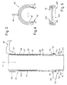
- Number 1 in Figures 1 and 2 indicates as a whole a flush device for a known flush tank not shown.
- Device 1 is a double-acting type for selectively discharging all or part of the water inside the tank.
- Device 1 extends substantially along an axis A, and comprises a supporting structure 2; a valve 3 controlled by a slide 4 movable along axis A inside structure 2; an actuating mechanism 5 for operating slide 4; and a height adjusting mechanism 6 for adjusting the height (measured along axis A) of structure 2.
- Structure 2 comprises a basket 8 having a cylindrical end portion 9 insertable in fluidtight and known manner inside a drain hole in the tank; a cup 10 fixed integrally to basket 8; and a frame 11 extending from and over cup 10 along axis A.
- Portion 9 comprises a drain hole 12 bounded by a peripheral edge defining a sealing seat 13.
- Cup 10 comprises two coaxial cylindrical lateral walls 14, 15 defining an annular chamber 16 closed at the bottom by a bottom wall 17; and the inner lateral wall 14 defines a cylindrical guide 18 through which slide 4 is housed.
- Annular chamber 16 houses a substantially toroidal float 20 mounted to slide freely about guide 18 and terminating with a top end edge 21.
- Float 20 defines an auxiliary member which is connectable selectively to slide 4 to vary the closing speed of valve 3 and selectively achieve full or partial flush.
- a top end of the outer lateral wall 15 has a radially outer thread 22 extending about axis A and having a thread pitch P1.
- Frame 11 comprises two rods 26 parallel to axis A; and a cross member 27 extending crosswise to axis A and integral with the top ends of rods 26.
- Beneath cross member 27, rods 26 have respective tabs 28 facing each other and positioned radially with respect to axis A; tabs 28 support respective aligned pins 29 defining an axis B radially perpendicular to axis A; beneath tabs 28, each rod 26 has a succession of teeth 30 equally spaced with a spacing P1; and teeth 30 project towards axis A and define a threaded coupling with thread 22 of cup 10.
- Frame 11 also comprises a ring 32 fitted to rotate about cup 10 and for securing teeth 30 to thread 22.
- Ring 32 comprises a lateral wall 33 substantially surrounding thread 22; and two seats 34 for housing rods 26.
- the ring supports an annular lever 35 hinged centrally to wall 33; and lever 35 is fitted, in diametrically opposite positions, with a rocking tooth 36 maintained by a spring 37 in an engaged position in which it is superimposed axially on edge 21 of float 20 to prevent upward axial movement of float 20, and with an eye 38 for releasing float 20 and having an elongated slot 39 parallel to axis A.
- Valve 3 comprises a shutter 40 fitted to slide 4 and cooperating with sealing seat 13.
- Slide 4 comprises two tubular members 41, 42 extending along axis A, inserted one inside the other, and slidable with respect to each other along axis A.
- Tubular member 41 is a substantially cylindrical tube which also acts as an overflow pipe; and tubular member 42 is a substantially cylindrical sleeve fitted radially loosely onto the outside of tube 41 so as to slide freely on tube 41 along axis A.
- tube 41 comprises a bottom portion 43 housed inside guide 18; an intermediate portion 44 bounded by opposite facing annular shoulders 45, 46; and a segmented top portion 47 extending outside cup 10.
- Portion 43 is fitted at the bottom end with shutter 40, and has longitudinal tabs 48 parallel to axis A and projecting radially from an outer lateral surface of portion 43 to engage respective grooves 49 formed in an inner lateral surface of guide 18, so that portion 43 (being secured angularly to guide 18) is only movable inside guide 18 along axis A.
- Portion 47 is defined by a succession of rings 50 defined by a number of parallel circumferential slits 51, and has longitudinal ribs 52 parallel to axis A and projecting radially from an outer lateral surface of portion 47 to engage respective grooves 53 formed in an inner lateral surface of sleeve 42, and so define circumferential retaining means preventing tube 41 and sleeve 42 from rotating with respect to each other, and connecting tube 41 and sleeve 42 angularly integral with each other.
- Sleeve 42 comprises an annular seat 54 located at the bottom end of sleeve 42 and defined by two parallel collars 55; and an externally threaded top portion 56 with a thread pitch P2.
- the top end of portion 56 supports an actuating member 57 connected to actuating mechanism 5.
- Actuating member 57 comprises an internally threaded ring 58 screwed to portion 56; and a hook 59 extending radially outwards from ring 58.
- Slide 4 has a connecting member 60 for connecting tube 41 and sleeve 42 axially integral with each other, with a predetermined axial clearance, when slide 4 is raised by actuating mechanism 5, and for limiting axial slide between tube 41 and sleeve 42 along axis A to a predetermined axial travel.
- Connecting member 60 is fitted to sleeve 42, and, as shown in Figures 4 and 5, comprises a radially open annular body 61 having an elastic opening 62 enabling it to click inside annular seat 54.
- Annular body 61 has a bottom edge 63 which cooperates axially with shoulder 46; and a circumferential projection 64 which cooperates axially with a stop member defined by shoulder 45. The distance between shoulders 45 and 46 is greater than the distance between edge 63 and projection 64, and defines the allowed axial travel of tubular members 41 and 42.
- Connecting member 60 also comprises an appendix 65, which projects radially outwards from annular body 61, is located diametrically opposite opening 62, and is inserted inside slot 39 to engage eye 38.
- actuating mechanism 5 comprises two buttons 71, 72 acting on a piston 73; a guide 74 fixed to cross member 27 and inside which piston 73 slides along axis A; and a transmission 75.
- Buttons 71 and 72 activate partial-flush and full-flush mode respectively, and are housed and slide inside respective seats permitting different axial travels of buttons 71, 72. Both buttons 71, 72 act on piston 73 to slide it inside guide 74, but the travel of piston 73 produced pressing partial-flush button 71 is shorter than that produced pressing full-flush button 72.
- Transmission 75 comprises a substantially rectangular lever 76 hinged to pins 29 about axis B and having an eye 77; and a lever 78 hinged to lever 76 about an axis C parallel to axis B, and having a member 79 cooperating with a bottom end of piston 73.
- Member 79 has projections 80 engaging tabs 28 to guide member 79 parallel to axis A when activated by piston 73.
- Eye 77 is engaged by hook 59 of actuating member 57, so that the movements of lever 76 are transmitted to actuating member 57 and vice versa.
- the height of structure 2 is adjusted by rotating cup 10 with respect to frame 11, by virtue of the threaded connection between cup 10 and frame 11. Rotation of cup 10 with respect to frame 11 also produces rotation of threaded portion 56 of slide 4 with respect to actuating member 57, thus altering the position of portion 56 with respect to actuating member 57.
- portion 47 of tube 41 and portion 56 of sleeve 42 projecting with respect to actuating member 57 may be cut off.
- Thread 22 of cup 10 and the thread of portion 56 of slide 4 turn in the same direction, and may have the same or slightly different pitches, any defects caused by differences in pitch being compensated by the axial clearance between tubular members 41, 42.
- the device is activated by button 71 or 72.
- lever 78 When button 71 is pressed, lever 78 is pressed down and lever 76 rotates about axis B to raise hook 59, actuating member 57, and therefore slide 4. More specifically, actuating member 57 pulls up sleeve 42, connecting member 60, and finally tube 41 with shutter 40, thus opening valve 3.
- the travel of sleeve 42 depends on the angle of rotation of lever 76 and the travel of button 71; the travel of button 71 is such that appendix 65 slides inside slot 39 without ever coming into contact with eye 38, so that lever 35 remains unmoved, and float 20 remains axially engaged by tooth 36; and slide 4 moves down by force of gravity to close valve 3, without being connected to float 20, thus obtaining a partial flush.
- button 72 when button 72 is pressed, lever 78 is pushed down and lever 76 rotates about axis B to raise hook 59, actuating member 57, sleeve 42, connecting member 60, and finally tube 41.
- the travel of button 72 is greater than that of button 71, so that appendix 65 slides inside slot 39 into contact with eye 38, thus rotating lever 35; the rotation of lever 35 rotates tooth 36 to release float 20, which is raised by hydrostatic thrust; and, when slide 4 moves down by force of gravity to close valve 3, edge 63 of connecting member 60 comes to rest on edge 21 of float 20, thus connecting slide 4 to float 20 and delaying the downward movement of slide 4 to achieve full flush.
Landscapes
- Health & Medical Sciences (AREA)
- Life Sciences & Earth Sciences (AREA)
- Engineering & Computer Science (AREA)
- Hydrology & Water Resources (AREA)
- Public Health (AREA)
- Water Supply & Treatment (AREA)
- Mechanically-Actuated Valves (AREA)
- Transmission Devices (AREA)
Abstract
Description
Claims (16)
- A flush device (1) for a flush tank, in particular a dual-flush tank, comprising a supporting structure (2), a valve (3) controlled by a slide (4) movable along an axis (A) inside the structure, and an actuating mechanism (5) for activating the slide (4); the device being characterized in that the slide (4) comprises two tubular members (41, 42) inserted one inside the other and connected to slide axially with respect to each other along said axis (A) with a predetermined axial clearance.
- A device as claimed in Claim 1, characterized in that the slide (4) comprises connecting means (60) for connecting said tubular members (41, 42) axially integral with each other, and for limiting axial slide between said tubular members (41, 42) to a predetermined axial travel.
- A device as claimed in Claim 1 or 2, characterized in that a radially outer tubular member (42) is fitted radially loosely about a radially inner tubular member (41), so as to slide freely on the radially inner tubular member (41) along said axis (A).
- A device as claimed in one of the foregoing Claims, characterized by comprising circumferential retaining means (52, 53) for preventing said tubular members (41, 42) from rotating with respect to each other, and for connecting said tubular members angularly integral with each other.
- A device as claimed in one of the foregoing Claims, characterized by comprising a connecting member (60) for connecting said tubular members (41, 42) axially integral with each other when said slide (4) is raised by the actuating mechanism (5).
- A device as claimed in Claim 5, characterized in that the connecting member (60) is carried integrally by a first tubular member (41), and comprises a projection (64) cooperating axially with a stop member (45) carried by a second tubular member (42).
- A device as claimed in Claim 6, characterized in that the connecting member (60) comprises a radially open annular body (61) clicked inside an annular seat (54) formed on an outer lateral wall of said second tubular member (42).
- A device as claimed in Claim 6 or 7, characterized in that said first tubular member (41) supports, at a bottom end, a shutter (40) cooperating with a sealing seat (13); and said second tubular member (42) supports, at a top end, an actuating member (57) connected to the actuating mechanism (5).
- A device as claimed in Claim 8, characterized in that said second tubular member (42) comprises an externally threaded top portion (56); and the actuating member (57) comprises a ring (58) screwed to the top portion (56), and a hook (59) carried by the ring (58).
- A device as claimed in one of Claims 5 to 9, characterized by comprising an auxiliary member (20) selectively connectable to the slide (4) to vary the closing speed of the valve (3) to selectively achieve a full flush and a partial flush.
- A device as claimed in Claim 10, characterized in that said auxiliary member (20) is activated by means of said connecting member (60).
- A device as claimed in Claim 11, characterized in that said auxiliary member is a float (20), and the connecting member (60) has an appendix (65) which engages an eye (38) to release the float (20).
- A device as claimed in any one of the foregoing Claims, characterized in that said structure (2) comprises a cup (10), and a frame (11) located over the cup; the cup (10) and the frame (11) being connected by a threaded coupling to adjust the height of the structure (2) along said axis (A) by rotating the cup (10) about said axis (A) with respect to the frame (11).
- A device as claimed in Claim 13, characterized in that said cup (10) comprises a guide (18) for guiding the slide (4) so that the slide (4) is movable solely along said axis (A); the actuating mechanism (5) comprising at least one button (71, 72) and a transmission (75), which are supported by the frame (11), and an actuating member (57) which is supported by the slide (4) and connected to the transmission (75) so as to be angularly integral with the frame (11) during rotation about said axis (A).
- A device as claimed in Claim 14, characterized in that said slide (4) has an externally threaded top portion (56) formed on one of said tubular members (41, 42); the actuating member (57) comprising a ring (58) screwed to said top portion (56).
- A device as claimed in one of Claims 13 to 15, characterized in that the cup (10) has a radially outer thread (22) extending about said axis (A); and the frame (11) comprises two rods (26) parallel to said axis (A) and having respective successions of teeth (30) which cooperate with said thread (22).
Applications Claiming Priority (2)
| Application Number | Priority Date | Filing Date | Title |
|---|---|---|---|
| IT000937A ITMI20030937A1 (en) | 2003-05-09 | 2003-05-09 | DISCHARGE DEVICE FOR A RINSING CASSETTE |
| ITMI20030937 | 2003-05-09 |
Publications (1)
| Publication Number | Publication Date |
|---|---|
| EP1477618A1 true EP1477618A1 (en) | 2004-11-17 |
Family
ID=33017974
Family Applications (1)
| Application Number | Title | Priority Date | Filing Date |
|---|---|---|---|
| EP04101998A Withdrawn EP1477618A1 (en) | 2003-05-09 | 2004-05-07 | Flush device for a flush tank, in particular a dual-flush tank |
Country Status (5)
| Country | Link |
|---|---|
| EP (1) | EP1477618A1 (en) |
| AU (1) | AU2004201937A1 (en) |
| IL (1) | IL161887A0 (en) |
| IT (1) | ITMI20030937A1 (en) |
| RU (1) | RU2351716C2 (en) |
Cited By (8)
| Publication number | Priority date | Publication date | Assignee | Title |
|---|---|---|---|---|
| WO2007056329A3 (en) * | 2005-11-07 | 2007-07-12 | Kohler Co | Canister flush valve |
| CN101824846A (en) * | 2010-04-28 | 2010-09-08 | 江苏财经职业技术学院 | Double-acting stepless drainage of flush toilet |
| ITMI20100017A1 (en) * | 2010-01-12 | 2011-07-13 | Oliveira & Irmao Sa | DISCHARGE VALVE GROUP WITH ADJUSTABLE HEIGHT FOR A RINSE CASSETTE |
| CN102605844A (en) * | 2012-04-11 | 2012-07-25 | 厦门瑞尔特卫浴工业有限公司 | Drive-by-wire mechanism of double-gear water drainage valve |
| CN102943516A (en) * | 2012-10-31 | 2013-02-27 | 厦门瑞尔特卫浴科技股份有限公司 | Water draining valve with guide structure |
| CN103489683A (en) * | 2013-08-27 | 2014-01-01 | 厦门瑞尔特卫浴科技股份有限公司 | Key structure |
| CN103572816A (en) * | 2013-11-05 | 2014-02-12 | 厦门瑞尔特卫浴科技股份有限公司 | Water replenishing device and application thereof |
| EP2672028A4 (en) * | 2011-01-31 | 2017-12-13 | Fominaya, S.A. | Cistern double-flush device |
Citations (3)
| Publication number | Priority date | Publication date | Assignee | Title |
|---|---|---|---|---|
| EP0801179A2 (en) * | 1996-04-10 | 1997-10-15 | Oliveira & Irmao S.A. | Device for controlling the discharge valve of a lavatory flush tank |
| EP0913532A2 (en) * | 1997-11-03 | 1999-05-06 | Oliveira & Irmao S.A. | Improvements to a device for controlling the water discharge valve of a cistern for sanitary apparatus |
| EP1245744A1 (en) * | 2001-03-29 | 2002-10-02 | VALSIR S.p.A. | Flush device for a lavatory flush tank |
Family Cites Families (2)
| Publication number | Priority date | Publication date | Assignee | Title |
|---|---|---|---|---|
| SU1502732A1 (en) * | 1988-01-13 | 1989-08-23 | Ю.А. Лещенко | Flush tank with variable water output |
| DE20204326U1 (en) * | 2001-04-09 | 2002-06-06 | PROSAN d.o.o., Ruše | Drain fitting for a cistern |
-
2003
- 2003-05-09 IT IT000937A patent/ITMI20030937A1/en unknown
-
2004
- 2004-05-07 EP EP04101998A patent/EP1477618A1/en not_active Withdrawn
- 2004-05-09 IL IL16188704A patent/IL161887A0/en active IP Right Grant
- 2004-05-10 AU AU2004201937A patent/AU2004201937A1/en not_active Abandoned
- 2004-05-11 RU RU2004114340/03A patent/RU2351716C2/en not_active IP Right Cessation
Patent Citations (3)
| Publication number | Priority date | Publication date | Assignee | Title |
|---|---|---|---|---|
| EP0801179A2 (en) * | 1996-04-10 | 1997-10-15 | Oliveira & Irmao S.A. | Device for controlling the discharge valve of a lavatory flush tank |
| EP0913532A2 (en) * | 1997-11-03 | 1999-05-06 | Oliveira & Irmao S.A. | Improvements to a device for controlling the water discharge valve of a cistern for sanitary apparatus |
| EP1245744A1 (en) * | 2001-03-29 | 2002-10-02 | VALSIR S.p.A. | Flush device for a lavatory flush tank |
Cited By (17)
| Publication number | Priority date | Publication date | Assignee | Title |
|---|---|---|---|---|
| WO2007056329A3 (en) * | 2005-11-07 | 2007-07-12 | Kohler Co | Canister flush valve |
| JP2009515069A (en) * | 2005-11-07 | 2009-04-09 | コーラー、カンパニー | Canister flush valve |
| US7634821B2 (en) | 2005-11-07 | 2009-12-22 | Kohler Co. | Canister flush valve |
| US7895684B2 (en) | 2005-11-07 | 2011-03-01 | Kohler Co. | Canister flush valve |
| CN101305138B (en) * | 2005-11-07 | 2011-06-08 | 科勒公司 | tank flush valve |
| RU2556982C2 (en) * | 2010-01-12 | 2015-07-20 | Оливейра Энд Ирмау, С.А. | Group of height-adjustable flushing valves for flushing tank |
| ITMI20100017A1 (en) * | 2010-01-12 | 2011-07-13 | Oliveira & Irmao Sa | DISCHARGE VALVE GROUP WITH ADJUSTABLE HEIGHT FOR A RINSE CASSETTE |
| WO2011086452A1 (en) * | 2010-01-12 | 2011-07-21 | Oliveira & Irmao, S.A. | Height-adjustable flushing valve group for a flushing tank |
| CN101824846B (en) * | 2010-04-28 | 2012-04-04 | 江苏财经职业技术学院 | Double-acting stepless drainage device for flush toilet |
| CN101824846A (en) * | 2010-04-28 | 2010-09-08 | 江苏财经职业技术学院 | Double-acting stepless drainage of flush toilet |
| EP2672028A4 (en) * | 2011-01-31 | 2017-12-13 | Fominaya, S.A. | Cistern double-flush device |
| CN102605844A (en) * | 2012-04-11 | 2012-07-25 | 厦门瑞尔特卫浴工业有限公司 | Drive-by-wire mechanism of double-gear water drainage valve |
| CN102943516A (en) * | 2012-10-31 | 2013-02-27 | 厦门瑞尔特卫浴科技股份有限公司 | Water draining valve with guide structure |
| CN103489683A (en) * | 2013-08-27 | 2014-01-01 | 厦门瑞尔特卫浴科技股份有限公司 | Key structure |
| CN103489683B (en) * | 2013-08-27 | 2015-09-30 | 厦门瑞尔特卫浴科技股份有限公司 | Press-key structure |
| CN103572816A (en) * | 2013-11-05 | 2014-02-12 | 厦门瑞尔特卫浴科技股份有限公司 | Water replenishing device and application thereof |
| CN103572816B (en) * | 2013-11-05 | 2015-05-20 | 厦门瑞尔特卫浴科技股份有限公司 | Water replenishing device and application thereof |
Also Published As
| Publication number | Publication date |
|---|---|
| RU2004114340A (en) | 2005-10-27 |
| ITMI20030937A1 (en) | 2004-11-10 |
| IL161887A0 (en) | 2005-11-20 |
| RU2351716C2 (en) | 2009-04-10 |
| AU2004201937A1 (en) | 2004-11-25 |
Similar Documents
| Publication | Publication Date | Title |
|---|---|---|
| US8584268B2 (en) | Dual flush toilet devices | |
| EP1477618A1 (en) | Flush device for a flush tank, in particular a dual-flush tank | |
| CN110185105B (en) | Flushing mechanism with system for blocking drawbar in position | |
| US20080295238A1 (en) | Dual Flush Toilet Mechanism | |
| EP1811092A2 (en) | Flushing valve mechanism | |
| EP0801179B1 (en) | Device for controlling the discharge valve of a lavatory flush tank | |
| RU2420633C2 (en) | Drain valve of flush tank with system of drained water amount control | |
| EP1353014A2 (en) | Fast-close feed valve for a lavatory flush tank | |
| EP1674623A2 (en) | Flush tank flush valve assembly | |
| US11959263B2 (en) | Drain for sanitary fixtures | |
| US3038491A (en) | Flush valve apparatus | |
| EP2799633B1 (en) | Flush tank drain valve assembly with a water outflow regulating system | |
| ES2585885T3 (en) | Mechanism to clean a toilet by discharging water | |
| EP3388588B1 (en) | Button assembly of a flushing device for a flush tank | |
| EP0943851B1 (en) | Float valve for accumulating water in a lavatory flush tank | |
| EP0874092A2 (en) | Float valve, with adjustable closing force, for feeding water into a lavatory flush tank | |
| RU2761877C2 (en) | Flushing device for toilet tank | |
| EP1795660A2 (en) | Flush tank drain valve assembly | |
| JP2535917Y2 (en) | Drain valve operating device in toilet bowl washing tank | |
| EP3363957B1 (en) | Feeding and flushing assembly of a flush tank | |
| EP1359261B1 (en) | Adaptable flush tank valve assembly, and method of fitting the valve assembly to a flush tank | |
| EP1428946A2 (en) | Valve assembly | |
| US10145095B1 (en) | Toilet bowl overflow prevention | |
| US1251804A (en) | Actuating device for automatic flush-tank valves. | |
| EP3356610A1 (en) | Flushing device for a flush tank |
Legal Events
| Date | Code | Title | Description |
|---|---|---|---|
| PUAI | Public reference made under article 153(3) epc to a published international application that has entered the european phase |
Free format text: ORIGINAL CODE: 0009012 |
|
| AK | Designated contracting states |
Kind code of ref document: A1 Designated state(s): AT BE BG CH CY CZ DE DK EE ES FI FR GB GR HU IE IT LI LU MC NL PL PT RO SE SI SK TR |
|
| AX | Request for extension of the european patent |
Extension state: AL HR LT LV MK |
|
| 17P | Request for examination filed |
Effective date: 20050511 |
|
| AKX | Designation fees paid |
Designated state(s): AT BE BG CH CY CZ DE DK EE ES FI FR GB GR HU IE IT LI LU MC NL PL PT RO SE SI SK TR |
|
| 17Q | First examination report despatched |
Effective date: 20070102 |
|
| STAA | Information on the status of an ep patent application or granted ep patent |
Free format text: STATUS: THE APPLICATION IS DEEMED TO BE WITHDRAWN |
|
| 18D | Application deemed to be withdrawn |
Effective date: 20111201 |