EP1477585A2 - Electrolytic electrode and process of producing the same - Google Patents
Electrolytic electrode and process of producing the same Download PDFInfo
- Publication number
- EP1477585A2 EP1477585A2 EP20040010837 EP04010837A EP1477585A2 EP 1477585 A2 EP1477585 A2 EP 1477585A2 EP 20040010837 EP20040010837 EP 20040010837 EP 04010837 A EP04010837 A EP 04010837A EP 1477585 A2 EP1477585 A2 EP 1477585A2
- Authority
- EP
- European Patent Office
- Prior art keywords
- temperature oxidation
- oxidation film
- electrode
- substrate
- electrolytic
- Prior art date
- Legal status (The legal status is an assumption and is not a legal conclusion. Google has not performed a legal analysis and makes no representation as to the accuracy of the status listed.)
- Granted
Links
- 238000000034 method Methods 0.000 title claims abstract description 37
- 230000008569 process Effects 0.000 title claims abstract description 13
- 230000003647 oxidation Effects 0.000 claims abstract description 169
- 238000007254 oxidation reaction Methods 0.000 claims abstract description 169
- 239000000758 substrate Substances 0.000 claims abstract description 117
- 239000003054 catalyst Substances 0.000 claims abstract description 78
- 229910052751 metal Inorganic materials 0.000 claims abstract description 31
- 239000002184 metal Substances 0.000 claims abstract description 31
- 238000010438 heat treatment Methods 0.000 claims abstract description 27
- 229910001092 metal group alloy Inorganic materials 0.000 claims abstract description 16
- GWEVSGVZZGPLCZ-UHFFFAOYSA-N Titan oxide Chemical compound O=[Ti]=O GWEVSGVZZGPLCZ-UHFFFAOYSA-N 0.000 claims description 52
- 238000000576 coating method Methods 0.000 claims description 21
- 239000011248 coating agent Substances 0.000 claims description 20
- 238000005979 thermal decomposition reaction Methods 0.000 claims description 11
- 239000011229 interlayer Substances 0.000 abstract description 20
- 230000007797 corrosion Effects 0.000 abstract description 13
- 238000005260 corrosion Methods 0.000 abstract description 13
- RTAQQCXQSZGOHL-UHFFFAOYSA-N Titanium Chemical compound [Ti] RTAQQCXQSZGOHL-UHFFFAOYSA-N 0.000 description 55
- 239000010936 titanium Substances 0.000 description 55
- 229910052719 titanium Inorganic materials 0.000 description 52
- 239000010410 layer Substances 0.000 description 44
- 230000000052 comparative effect Effects 0.000 description 35
- 238000005868 electrolysis reaction Methods 0.000 description 26
- 229910052760 oxygen Inorganic materials 0.000 description 25
- QVGXLLKOCUKJST-UHFFFAOYSA-N atomic oxygen Chemical compound [O] QVGXLLKOCUKJST-UHFFFAOYSA-N 0.000 description 24
- 239000001301 oxygen Substances 0.000 description 24
- VEXZGXHMUGYJMC-UHFFFAOYSA-N Hydrochloric acid Chemical compound Cl VEXZGXHMUGYJMC-UHFFFAOYSA-N 0.000 description 20
- 150000002500 ions Chemical class 0.000 description 20
- 230000015572 biosynthetic process Effects 0.000 description 16
- 238000002347 injection Methods 0.000 description 14
- 239000007924 injection Substances 0.000 description 14
- BASFCYQUMIYNBI-UHFFFAOYSA-N platinum Chemical group [Pt] BASFCYQUMIYNBI-UHFFFAOYSA-N 0.000 description 14
- 229910052715 tantalum Inorganic materials 0.000 description 13
- PXHVJJICTQNCMI-UHFFFAOYSA-N Nickel Chemical compound [Ni] PXHVJJICTQNCMI-UHFFFAOYSA-N 0.000 description 11
- HTXDPTMKBJXEOW-UHFFFAOYSA-N dioxoiridium Chemical compound O=[Ir]=O HTXDPTMKBJXEOW-UHFFFAOYSA-N 0.000 description 11
- QAOWNCQODCNURD-UHFFFAOYSA-N Sulfuric acid Chemical compound OS(O)(=O)=O QAOWNCQODCNURD-UHFFFAOYSA-N 0.000 description 10
- 229910052741 iridium Inorganic materials 0.000 description 9
- GKOZUEZYRPOHIO-UHFFFAOYSA-N iridium atom Chemical compound [Ir] GKOZUEZYRPOHIO-UHFFFAOYSA-N 0.000 description 9
- GUVRBAGPIYLISA-UHFFFAOYSA-N tantalum atom Chemical compound [Ta] GUVRBAGPIYLISA-UHFFFAOYSA-N 0.000 description 9
- OEIMLTQPLAGXMX-UHFFFAOYSA-I tantalum(v) chloride Chemical compound Cl[Ta](Cl)(Cl)(Cl)Cl OEIMLTQPLAGXMX-UHFFFAOYSA-I 0.000 description 9
- 239000007789 gas Substances 0.000 description 8
- 229910000457 iridium oxide Inorganic materials 0.000 description 8
- BPUBBGLMJRNUCC-UHFFFAOYSA-N oxygen(2-);tantalum(5+) Chemical compound [O-2].[O-2].[O-2].[O-2].[O-2].[Ta+5].[Ta+5] BPUBBGLMJRNUCC-UHFFFAOYSA-N 0.000 description 8
- 229910001936 tantalum oxide Inorganic materials 0.000 description 8
- 238000012360 testing method Methods 0.000 description 8
- OGIDPMRJRNCKJF-UHFFFAOYSA-N titanium oxide Inorganic materials [Ti]=O OGIDPMRJRNCKJF-UHFFFAOYSA-N 0.000 description 8
- 238000002441 X-ray diffraction Methods 0.000 description 7
- 238000001816 cooling Methods 0.000 description 7
- 239000000523 sample Substances 0.000 description 7
- XLYOFNOQVPJJNP-UHFFFAOYSA-N water Substances O XLYOFNOQVPJJNP-UHFFFAOYSA-N 0.000 description 7
- LDXJRKWFNNFDSA-UHFFFAOYSA-N 2-(2,4,6,7-tetrahydrotriazolo[4,5-c]pyridin-5-yl)-1-[4-[2-[[3-(trifluoromethoxy)phenyl]methylamino]pyrimidin-5-yl]piperazin-1-yl]ethanone Chemical compound C1CN(CC2=NNN=C21)CC(=O)N3CCN(CC3)C4=CN=C(N=C4)NCC5=CC(=CC=C5)OC(F)(F)F LDXJRKWFNNFDSA-UHFFFAOYSA-N 0.000 description 6
- 229910001069 Ti alloy Inorganic materials 0.000 description 6
- 238000006243 chemical reaction Methods 0.000 description 6
- 230000000694 effects Effects 0.000 description 6
- 229910052759 nickel Inorganic materials 0.000 description 6
- HMUNWXXNJPVALC-UHFFFAOYSA-N 1-[4-[2-(2,3-dihydro-1H-inden-2-ylamino)pyrimidin-5-yl]piperazin-1-yl]-2-(2,4,6,7-tetrahydrotriazolo[4,5-c]pyridin-5-yl)ethanone Chemical compound C1C(CC2=CC=CC=C12)NC1=NC=C(C=N1)N1CCN(CC1)C(CN1CC2=C(CC1)NN=N2)=O HMUNWXXNJPVALC-UHFFFAOYSA-N 0.000 description 5
- 238000004458 analytical method Methods 0.000 description 5
- 238000005422 blasting Methods 0.000 description 5
- 238000009835 boiling Methods 0.000 description 5
- 238000004140 cleaning Methods 0.000 description 5
- 229910044991 metal oxide Inorganic materials 0.000 description 5
- 239000000203 mixture Substances 0.000 description 5
- 229910000476 molybdenum oxide Inorganic materials 0.000 description 5
- 230000001590 oxidative effect Effects 0.000 description 5
- PQQKPALAQIIWST-UHFFFAOYSA-N oxomolybdenum Chemical compound [Mo]=O PQQKPALAQIIWST-UHFFFAOYSA-N 0.000 description 5
- 229910052697 platinum Inorganic materials 0.000 description 5
- 239000002356 single layer Substances 0.000 description 5
- 239000000243 solution Substances 0.000 description 5
- 230000003746 surface roughness Effects 0.000 description 5
- 239000007864 aqueous solution Substances 0.000 description 4
- 239000002131 composite material Substances 0.000 description 4
- 238000005530 etching Methods 0.000 description 4
- 238000009472 formulation Methods 0.000 description 4
- 238000004519 manufacturing process Methods 0.000 description 4
- 239000011259 mixed solution Substances 0.000 description 4
- 238000012986 modification Methods 0.000 description 4
- 230000004048 modification Effects 0.000 description 4
- JKQOBWVOAYFWKG-UHFFFAOYSA-N molybdenum trioxide Chemical compound O=[Mo](=O)=O JKQOBWVOAYFWKG-UHFFFAOYSA-N 0.000 description 4
- PDKHNCYLMVRIFV-UHFFFAOYSA-H molybdenum;hexachloride Chemical compound [Cl-].[Cl-].[Cl-].[Cl-].[Cl-].[Cl-].[Mo] PDKHNCYLMVRIFV-UHFFFAOYSA-H 0.000 description 4
- 229910052758 niobium Inorganic materials 0.000 description 4
- 239000010955 niobium Substances 0.000 description 4
- GUCVJGMIXFAOAE-UHFFFAOYSA-N niobium atom Chemical compound [Nb] GUCVJGMIXFAOAE-UHFFFAOYSA-N 0.000 description 4
- 239000002245 particle Substances 0.000 description 4
- 239000002344 surface layer Substances 0.000 description 4
- DANYXEHCMQHDNX-UHFFFAOYSA-K trichloroiridium Chemical compound Cl[Ir](Cl)Cl DANYXEHCMQHDNX-UHFFFAOYSA-K 0.000 description 4
- VZSRBBMJRBPUNF-UHFFFAOYSA-N 2-(2,3-dihydro-1H-inden-2-ylamino)-N-[3-oxo-3-(2,4,6,7-tetrahydrotriazolo[4,5-c]pyridin-5-yl)propyl]pyrimidine-5-carboxamide Chemical compound C1C(CC2=CC=CC=C12)NC1=NC=C(C=N1)C(=O)NCCC(N1CC2=C(CC1)NN=N2)=O VZSRBBMJRBPUNF-UHFFFAOYSA-N 0.000 description 3
- ZAMOUSCENKQFHK-UHFFFAOYSA-N Chlorine atom Chemical compound [Cl] ZAMOUSCENKQFHK-UHFFFAOYSA-N 0.000 description 3
- AFCARXCZXQIEQB-UHFFFAOYSA-N N-[3-oxo-3-(2,4,6,7-tetrahydrotriazolo[4,5-c]pyridin-5-yl)propyl]-2-[[3-(trifluoromethoxy)phenyl]methylamino]pyrimidine-5-carboxamide Chemical compound O=C(CCNC(=O)C=1C=NC(=NC=1)NCC1=CC(=CC=C1)OC(F)(F)F)N1CC2=C(CC1)NN=N2 AFCARXCZXQIEQB-UHFFFAOYSA-N 0.000 description 3
- MUBZPKHOEPUJKR-UHFFFAOYSA-N Oxalic acid Chemical compound OC(=O)C(O)=O MUBZPKHOEPUJKR-UHFFFAOYSA-N 0.000 description 3
- HEMHJVSKTPXQMS-UHFFFAOYSA-M Sodium hydroxide Chemical compound [OH-].[Na+] HEMHJVSKTPXQMS-UHFFFAOYSA-M 0.000 description 3
- 230000002159 abnormal effect Effects 0.000 description 3
- 239000000654 additive Substances 0.000 description 3
- 230000000996 additive effect Effects 0.000 description 3
- PNEYBMLMFCGWSK-UHFFFAOYSA-N aluminium oxide Inorganic materials [O-2].[O-2].[O-2].[Al+3].[Al+3] PNEYBMLMFCGWSK-UHFFFAOYSA-N 0.000 description 3
- 239000000460 chlorine Substances 0.000 description 3
- 238000009792 diffusion process Methods 0.000 description 3
- 238000007598 dipping method Methods 0.000 description 3
- 239000003792 electrolyte Substances 0.000 description 3
- 239000000463 material Substances 0.000 description 3
- QSHDDOUJBYECFT-UHFFFAOYSA-N mercury Chemical compound [Hg] QSHDDOUJBYECFT-UHFFFAOYSA-N 0.000 description 3
- 229910052753 mercury Inorganic materials 0.000 description 3
- 150000002739 metals Chemical class 0.000 description 3
- -1 platinum group metal oxide Chemical class 0.000 description 3
- 238000012545 processing Methods 0.000 description 3
- 239000000047 product Substances 0.000 description 3
- 230000000630 rising effect Effects 0.000 description 3
- 229910001925 ruthenium oxide Inorganic materials 0.000 description 3
- WOCIAKWEIIZHES-UHFFFAOYSA-N ruthenium(iv) oxide Chemical compound O=[Ru]=O WOCIAKWEIIZHES-UHFFFAOYSA-N 0.000 description 3
- 150000003839 salts Chemical class 0.000 description 3
- 239000000126 substance Substances 0.000 description 3
- OHVLMTFVQDZYHP-UHFFFAOYSA-N 1-(2,4,6,7-tetrahydrotriazolo[4,5-c]pyridin-5-yl)-2-[4-[2-[[3-(trifluoromethoxy)phenyl]methylamino]pyrimidin-5-yl]piperazin-1-yl]ethanone Chemical compound N1N=NC=2CN(CCC=21)C(CN1CCN(CC1)C=1C=NC(=NC=1)NCC1=CC(=CC=C1)OC(F)(F)F)=O OHVLMTFVQDZYHP-UHFFFAOYSA-N 0.000 description 2
- YLZOPXRUQYQQID-UHFFFAOYSA-N 3-(2,4,6,7-tetrahydrotriazolo[4,5-c]pyridin-5-yl)-1-[4-[2-[[3-(trifluoromethoxy)phenyl]methylamino]pyrimidin-5-yl]piperazin-1-yl]propan-1-one Chemical compound N1N=NC=2CN(CCC=21)CCC(=O)N1CCN(CC1)C=1C=NC(=NC=1)NCC1=CC(=CC=C1)OC(F)(F)F YLZOPXRUQYQQID-UHFFFAOYSA-N 0.000 description 2
- DEXFNLNNUZKHNO-UHFFFAOYSA-N 6-[3-[4-[2-(2,3-dihydro-1H-inden-2-ylamino)pyrimidin-5-yl]piperidin-1-yl]-3-oxopropyl]-3H-1,3-benzoxazol-2-one Chemical compound C1C(CC2=CC=CC=C12)NC1=NC=C(C=N1)C1CCN(CC1)C(CCC1=CC2=C(NC(O2)=O)C=C1)=O DEXFNLNNUZKHNO-UHFFFAOYSA-N 0.000 description 2
- QGZKDVFQNNGYKY-UHFFFAOYSA-N Ammonia Chemical compound N QGZKDVFQNNGYKY-UHFFFAOYSA-N 0.000 description 2
- XKRFYHLGVUSROY-UHFFFAOYSA-N Argon Chemical compound [Ar] XKRFYHLGVUSROY-UHFFFAOYSA-N 0.000 description 2
- CURLTUGMZLYLDI-UHFFFAOYSA-N Carbon dioxide Chemical compound O=C=O CURLTUGMZLYLDI-UHFFFAOYSA-N 0.000 description 2
- 229910000975 Carbon steel Inorganic materials 0.000 description 2
- RYGMFSIKBFXOCR-UHFFFAOYSA-N Copper Chemical compound [Cu] RYGMFSIKBFXOCR-UHFFFAOYSA-N 0.000 description 2
- UFHFLCQGNIYNRP-UHFFFAOYSA-N Hydrogen Chemical compound [H][H] UFHFLCQGNIYNRP-UHFFFAOYSA-N 0.000 description 2
- XEEYBQQBJWHFJM-UHFFFAOYSA-N Iron Chemical compound [Fe] XEEYBQQBJWHFJM-UHFFFAOYSA-N 0.000 description 2
- 229910009972 Ti2Ni Inorganic materials 0.000 description 2
- ATJFFYVFTNAWJD-UHFFFAOYSA-N Tin Chemical compound [Sn] ATJFFYVFTNAWJD-UHFFFAOYSA-N 0.000 description 2
- HCHKCACWOHOZIP-UHFFFAOYSA-N Zinc Chemical compound [Zn] HCHKCACWOHOZIP-UHFFFAOYSA-N 0.000 description 2
- 239000002253 acid Substances 0.000 description 2
- 230000009471 action Effects 0.000 description 2
- 230000002411 adverse Effects 0.000 description 2
- 229910045601 alloy Inorganic materials 0.000 description 2
- 239000000956 alloy Substances 0.000 description 2
- 229910052782 aluminium Inorganic materials 0.000 description 2
- XAGFODPZIPBFFR-UHFFFAOYSA-N aluminium Chemical compound [Al] XAGFODPZIPBFFR-UHFFFAOYSA-N 0.000 description 2
- 239000010962 carbon steel Substances 0.000 description 2
- 229910052801 chlorine Inorganic materials 0.000 description 2
- 238000007796 conventional method Methods 0.000 description 2
- 239000011889 copper foil Substances 0.000 description 2
- 239000013078 crystal Substances 0.000 description 2
- 238000005520 cutting process Methods 0.000 description 2
- 230000007547 defect Effects 0.000 description 2
- 230000002950 deficient Effects 0.000 description 2
- 238000009826 distribution Methods 0.000 description 2
- 238000001035 drying Methods 0.000 description 2
- 239000012535 impurity Substances 0.000 description 2
- 229910000765 intermetallic Inorganic materials 0.000 description 2
- 239000007788 liquid Substances 0.000 description 2
- 238000005259 measurement Methods 0.000 description 2
- 150000004706 metal oxides Chemical class 0.000 description 2
- 238000002203 pretreatment Methods 0.000 description 2
- 230000005855 radiation Effects 0.000 description 2
- 239000004065 semiconductor Substances 0.000 description 2
- 230000000087 stabilizing effect Effects 0.000 description 2
- 238000010301 surface-oxidation reaction Methods 0.000 description 2
- 230000002195 synergetic effect Effects 0.000 description 2
- PBCFLUZVCVVTBY-UHFFFAOYSA-N tantalum pentoxide Inorganic materials O=[Ta](=O)O[Ta](=O)=O PBCFLUZVCVVTBY-UHFFFAOYSA-N 0.000 description 2
- 238000003466 welding Methods 0.000 description 2
- 229910052725 zinc Inorganic materials 0.000 description 2
- 239000011701 zinc Substances 0.000 description 2
- WZFUQSJFWNHZHM-UHFFFAOYSA-N 2-[4-[2-(2,3-dihydro-1H-inden-2-ylamino)pyrimidin-5-yl]piperazin-1-yl]-1-(2,4,6,7-tetrahydrotriazolo[4,5-c]pyridin-5-yl)ethanone Chemical compound C1C(CC2=CC=CC=C12)NC1=NC=C(C=N1)N1CCN(CC1)CC(=O)N1CC2=C(CC1)NN=N2 WZFUQSJFWNHZHM-UHFFFAOYSA-N 0.000 description 1
- 238000004438 BET method Methods 0.000 description 1
- VEXZGXHMUGYJMC-UHFFFAOYSA-M Chloride anion Chemical compound [Cl-] VEXZGXHMUGYJMC-UHFFFAOYSA-M 0.000 description 1
- 229910015221 MoCl5 Inorganic materials 0.000 description 1
- ZOKXTWBITQBERF-UHFFFAOYSA-N Molybdenum Chemical compound [Mo] ZOKXTWBITQBERF-UHFFFAOYSA-N 0.000 description 1
- 229910000990 Ni alloy Inorganic materials 0.000 description 1
- CBENFWSGALASAD-UHFFFAOYSA-N Ozone Chemical compound [O-][O+]=O CBENFWSGALASAD-UHFFFAOYSA-N 0.000 description 1
- 229910001362 Ta alloys Inorganic materials 0.000 description 1
- 229910004537 TaCl5 Inorganic materials 0.000 description 1
- QCWXUUIWCKQGHC-UHFFFAOYSA-N Zirconium Chemical compound [Zr] QCWXUUIWCKQGHC-UHFFFAOYSA-N 0.000 description 1
- 238000005299 abrasion Methods 0.000 description 1
- 230000002378 acidificating effect Effects 0.000 description 1
- 239000003570 air Substances 0.000 description 1
- 229910021529 ammonia Inorganic materials 0.000 description 1
- 238000000137 annealing Methods 0.000 description 1
- 229910052786 argon Inorganic materials 0.000 description 1
- 230000005540 biological transmission Effects 0.000 description 1
- 239000006227 byproduct Substances 0.000 description 1
- 238000004364 calculation method Methods 0.000 description 1
- 239000001569 carbon dioxide Substances 0.000 description 1
- 229910002092 carbon dioxide Inorganic materials 0.000 description 1
- 239000012159 carrier gas Substances 0.000 description 1
- 230000003197 catalytic effect Effects 0.000 description 1
- 230000008859 change Effects 0.000 description 1
- 238000005229 chemical vapour deposition Methods 0.000 description 1
- 229910001902 chlorine oxide Inorganic materials 0.000 description 1
- 230000003749 cleanliness Effects 0.000 description 1
- 239000011247 coating layer Substances 0.000 description 1
- 239000000567 combustion gas Substances 0.000 description 1
- 239000011529 conductive interlayer Substances 0.000 description 1
- 238000000354 decomposition reaction Methods 0.000 description 1
- 230000003111 delayed effect Effects 0.000 description 1
- 230000006866 deterioration Effects 0.000 description 1
- 238000004090 dissolution Methods 0.000 description 1
- 238000003487 electrochemical reaction Methods 0.000 description 1
- 230000005674 electromagnetic induction Effects 0.000 description 1
- 238000010894 electron beam technology Methods 0.000 description 1
- 238000004453 electron probe microanalysis Methods 0.000 description 1
- 238000001962 electrophoresis Methods 0.000 description 1
- 238000000572 ellipsometry Methods 0.000 description 1
- 238000010828 elution Methods 0.000 description 1
- 238000005516 engineering process Methods 0.000 description 1
- 230000005484 gravity Effects 0.000 description 1
- KRHYYFGTRYWZRS-UHFFFAOYSA-N hydrofluoric acid Substances F KRHYYFGTRYWZRS-UHFFFAOYSA-N 0.000 description 1
- GPRLSGONYQIRFK-UHFFFAOYSA-N hydron Chemical compound [H+] GPRLSGONYQIRFK-UHFFFAOYSA-N 0.000 description 1
- QWPPOHNGKGFGJK-UHFFFAOYSA-N hypochlorous acid Chemical compound ClO QWPPOHNGKGFGJK-UHFFFAOYSA-N 0.000 description 1
- 239000011261 inert gas Substances 0.000 description 1
- 229910052742 iron Inorganic materials 0.000 description 1
- 229910000953 kanthal Inorganic materials 0.000 description 1
- 230000007246 mechanism Effects 0.000 description 1
- 238000002844 melting Methods 0.000 description 1
- 230000008018 melting Effects 0.000 description 1
- 239000002052 molecular layer Substances 0.000 description 1
- 229910052750 molybdenum Inorganic materials 0.000 description 1
- 239000011733 molybdenum Substances 0.000 description 1
- GICWIDZXWJGTCI-UHFFFAOYSA-I molybdenum pentachloride Chemical compound Cl[Mo](Cl)(Cl)(Cl)Cl GICWIDZXWJGTCI-UHFFFAOYSA-I 0.000 description 1
- 229910001120 nichrome Inorganic materials 0.000 description 1
- 235000014593 oils and fats Nutrition 0.000 description 1
- 230000003287 optical effect Effects 0.000 description 1
- 239000011368 organic material Substances 0.000 description 1
- 235000006408 oxalic acid Nutrition 0.000 description 1
- HBEQXAKJSGXAIQ-UHFFFAOYSA-N oxopalladium Chemical compound [Pd]=O HBEQXAKJSGXAIQ-UHFFFAOYSA-N 0.000 description 1
- MUMZUERVLWJKNR-UHFFFAOYSA-N oxoplatinum Chemical compound [Pt]=O MUMZUERVLWJKNR-UHFFFAOYSA-N 0.000 description 1
- SJLOMQIUPFZJAN-UHFFFAOYSA-N oxorhodium Chemical compound [Rh]=O SJLOMQIUPFZJAN-UHFFFAOYSA-N 0.000 description 1
- 229910003445 palladium oxide Inorganic materials 0.000 description 1
- 229910003446 platinum oxide Inorganic materials 0.000 description 1
- 230000002035 prolonged effect Effects 0.000 description 1
- 238000004080 punching Methods 0.000 description 1
- 238000011158 quantitative evaluation Methods 0.000 description 1
- 229910003450 rhodium oxide Inorganic materials 0.000 description 1
- 238000005096 rolling process Methods 0.000 description 1
- 238000005201 scrubbing Methods 0.000 description 1
- 238000007086 side reaction Methods 0.000 description 1
- 238000003980 solgel method Methods 0.000 description 1
- 239000007787 solid Substances 0.000 description 1
- 238000001179 sorption measurement Methods 0.000 description 1
- 238000013020 steam cleaning Methods 0.000 description 1
- 239000008399 tap water Substances 0.000 description 1
- 235000020679 tap water Nutrition 0.000 description 1
- XOLBLPGZBRYERU-UHFFFAOYSA-N tin dioxide Chemical compound O=[Sn]=O XOLBLPGZBRYERU-UHFFFAOYSA-N 0.000 description 1
- 229910001887 tin oxide Inorganic materials 0.000 description 1
- 230000007704 transition Effects 0.000 description 1
- 238000004506 ultrasonic cleaning Methods 0.000 description 1
- 238000005406 washing Methods 0.000 description 1
- 239000002699 waste material Substances 0.000 description 1
- 229910052726 zirconium Inorganic materials 0.000 description 1
Images

Classifications
-
- C—CHEMISTRY; METALLURGY
- C25—ELECTROLYTIC OR ELECTROPHORETIC PROCESSES; APPARATUS THEREFOR
- C25B—ELECTROLYTIC OR ELECTROPHORETIC PROCESSES FOR THE PRODUCTION OF COMPOUNDS OR NON-METALS; APPARATUS THEREFOR
- C25B11/00—Electrodes; Manufacture thereof not otherwise provided for
- C25B11/04—Electrodes; Manufacture thereof not otherwise provided for characterised by the material
- C25B11/051—Electrodes formed of electrocatalysts on a substrate or carrier
- C25B11/055—Electrodes formed of electrocatalysts on a substrate or carrier characterised by the substrate or carrier material
- C25B11/057—Electrodes formed of electrocatalysts on a substrate or carrier characterised by the substrate or carrier material consisting of a single element or compound
- C25B11/061—Metal or alloy
- C25B11/063—Valve metal, e.g. titanium
-
- C—CHEMISTRY; METALLURGY
- C23—COATING METALLIC MATERIAL; COATING MATERIAL WITH METALLIC MATERIAL; CHEMICAL SURFACE TREATMENT; DIFFUSION TREATMENT OF METALLIC MATERIAL; COATING BY VACUUM EVAPORATION, BY SPUTTERING, BY ION IMPLANTATION OR BY CHEMICAL VAPOUR DEPOSITION, IN GENERAL; INHIBITING CORROSION OF METALLIC MATERIAL OR INCRUSTATION IN GENERAL
- C23C—COATING METALLIC MATERIAL; COATING MATERIAL WITH METALLIC MATERIAL; SURFACE TREATMENT OF METALLIC MATERIAL BY DIFFUSION INTO THE SURFACE, BY CHEMICAL CONVERSION OR SUBSTITUTION; COATING BY VACUUM EVAPORATION, BY SPUTTERING, BY ION IMPLANTATION OR BY CHEMICAL VAPOUR DEPOSITION, IN GENERAL
- C23C18/00—Chemical coating by decomposition of either liquid compounds or solutions of the coating forming compounds, without leaving reaction products of surface material in the coating; Contact plating
- C23C18/02—Chemical coating by decomposition of either liquid compounds or solutions of the coating forming compounds, without leaving reaction products of surface material in the coating; Contact plating by thermal decomposition
- C23C18/12—Chemical coating by decomposition of either liquid compounds or solutions of the coating forming compounds, without leaving reaction products of surface material in the coating; Contact plating by thermal decomposition characterised by the deposition of inorganic material other than metallic material
- C23C18/1204—Chemical coating by decomposition of either liquid compounds or solutions of the coating forming compounds, without leaving reaction products of surface material in the coating; Contact plating by thermal decomposition characterised by the deposition of inorganic material other than metallic material inorganic material, e.g. non-oxide and non-metallic such as sulfides, nitrides based compounds
- C23C18/1208—Oxides, e.g. ceramics
- C23C18/1216—Metal oxides
-
- C—CHEMISTRY; METALLURGY
- C23—COATING METALLIC MATERIAL; COATING MATERIAL WITH METALLIC MATERIAL; CHEMICAL SURFACE TREATMENT; DIFFUSION TREATMENT OF METALLIC MATERIAL; COATING BY VACUUM EVAPORATION, BY SPUTTERING, BY ION IMPLANTATION OR BY CHEMICAL VAPOUR DEPOSITION, IN GENERAL; INHIBITING CORROSION OF METALLIC MATERIAL OR INCRUSTATION IN GENERAL
- C23C—COATING METALLIC MATERIAL; COATING MATERIAL WITH METALLIC MATERIAL; SURFACE TREATMENT OF METALLIC MATERIAL BY DIFFUSION INTO THE SURFACE, BY CHEMICAL CONVERSION OR SUBSTITUTION; COATING BY VACUUM EVAPORATION, BY SPUTTERING, BY ION IMPLANTATION OR BY CHEMICAL VAPOUR DEPOSITION, IN GENERAL
- C23C18/00—Chemical coating by decomposition of either liquid compounds or solutions of the coating forming compounds, without leaving reaction products of surface material in the coating; Contact plating
- C23C18/02—Chemical coating by decomposition of either liquid compounds or solutions of the coating forming compounds, without leaving reaction products of surface material in the coating; Contact plating by thermal decomposition
- C23C18/12—Chemical coating by decomposition of either liquid compounds or solutions of the coating forming compounds, without leaving reaction products of surface material in the coating; Contact plating by thermal decomposition characterised by the deposition of inorganic material other than metallic material
- C23C18/1229—Composition of the substrate
- C23C18/1241—Metallic substrates
-
- C—CHEMISTRY; METALLURGY
- C23—COATING METALLIC MATERIAL; COATING MATERIAL WITH METALLIC MATERIAL; CHEMICAL SURFACE TREATMENT; DIFFUSION TREATMENT OF METALLIC MATERIAL; COATING BY VACUUM EVAPORATION, BY SPUTTERING, BY ION IMPLANTATION OR BY CHEMICAL VAPOUR DEPOSITION, IN GENERAL; INHIBITING CORROSION OF METALLIC MATERIAL OR INCRUSTATION IN GENERAL
- C23C—COATING METALLIC MATERIAL; COATING MATERIAL WITH METALLIC MATERIAL; SURFACE TREATMENT OF METALLIC MATERIAL BY DIFFUSION INTO THE SURFACE, BY CHEMICAL CONVERSION OR SUBSTITUTION; COATING BY VACUUM EVAPORATION, BY SPUTTERING, BY ION IMPLANTATION OR BY CHEMICAL VAPOUR DEPOSITION, IN GENERAL
- C23C18/00—Chemical coating by decomposition of either liquid compounds or solutions of the coating forming compounds, without leaving reaction products of surface material in the coating; Contact plating
- C23C18/02—Chemical coating by decomposition of either liquid compounds or solutions of the coating forming compounds, without leaving reaction products of surface material in the coating; Contact plating by thermal decomposition
- C23C18/12—Chemical coating by decomposition of either liquid compounds or solutions of the coating forming compounds, without leaving reaction products of surface material in the coating; Contact plating by thermal decomposition characterised by the deposition of inorganic material other than metallic material
- C23C18/125—Process of deposition of the inorganic material
- C23C18/1279—Process of deposition of the inorganic material performed under reactive atmosphere, e.g. oxidising or reducing atmospheres
-
- C—CHEMISTRY; METALLURGY
- C23—COATING METALLIC MATERIAL; COATING MATERIAL WITH METALLIC MATERIAL; CHEMICAL SURFACE TREATMENT; DIFFUSION TREATMENT OF METALLIC MATERIAL; COATING BY VACUUM EVAPORATION, BY SPUTTERING, BY ION IMPLANTATION OR BY CHEMICAL VAPOUR DEPOSITION, IN GENERAL; INHIBITING CORROSION OF METALLIC MATERIAL OR INCRUSTATION IN GENERAL
- C23C—COATING METALLIC MATERIAL; COATING MATERIAL WITH METALLIC MATERIAL; SURFACE TREATMENT OF METALLIC MATERIAL BY DIFFUSION INTO THE SURFACE, BY CHEMICAL CONVERSION OR SUBSTITUTION; COATING BY VACUUM EVAPORATION, BY SPUTTERING, BY ION IMPLANTATION OR BY CHEMICAL VAPOUR DEPOSITION, IN GENERAL
- C23C18/00—Chemical coating by decomposition of either liquid compounds or solutions of the coating forming compounds, without leaving reaction products of surface material in the coating; Contact plating
- C23C18/02—Chemical coating by decomposition of either liquid compounds or solutions of the coating forming compounds, without leaving reaction products of surface material in the coating; Contact plating by thermal decomposition
- C23C18/12—Chemical coating by decomposition of either liquid compounds or solutions of the coating forming compounds, without leaving reaction products of surface material in the coating; Contact plating by thermal decomposition characterised by the deposition of inorganic material other than metallic material
- C23C18/125—Process of deposition of the inorganic material
- C23C18/1295—Process of deposition of the inorganic material with after-treatment of the deposited inorganic material
-
- C—CHEMISTRY; METALLURGY
- C25—ELECTROLYTIC OR ELECTROPHORETIC PROCESSES; APPARATUS THEREFOR
- C25B—ELECTROLYTIC OR ELECTROPHORETIC PROCESSES FOR THE PRODUCTION OF COMPOUNDS OR NON-METALS; APPARATUS THEREFOR
- C25B11/00—Electrodes; Manufacture thereof not otherwise provided for
- C25B11/04—Electrodes; Manufacture thereof not otherwise provided for characterised by the material
- C25B11/051—Electrodes formed of electrocatalysts on a substrate or carrier
- C25B11/073—Electrodes formed of electrocatalysts on a substrate or carrier characterised by the electrocatalyst material
-
- C—CHEMISTRY; METALLURGY
- C25—ELECTROLYTIC OR ELECTROPHORETIC PROCESSES; APPARATUS THEREFOR
- C25D—PROCESSES FOR THE ELECTROLYTIC OR ELECTROPHORETIC PRODUCTION OF COATINGS; ELECTROFORMING; APPARATUS THEREFOR
- C25D17/00—Constructional parts, or assemblies thereof, of cells for electrolytic coating
- C25D17/10—Electrodes, e.g. composition, counter electrode
Definitions
- the present invention relates to an electrolytic electrode that is used in various industrial electrolyses, and a process of producing the same.
- the present invention relates to an anode for generating oxygen, which is used in the industrial electrolysis for electrolytic copper foil manufacture, aluminum in-liquid power feed, and continuous electrolytic zinc-coated carbon steel sheet manufacture, and the like, and a process of producing the same.
- the ruthenium oxide electrode catalyst that is usually used for the generation of chlorine can be used to and extent of about 90% of the catalyst-supporting amount.
- the iridium oxide electrode catalyst that is frequently used for the generation of oxygen can be used to an extent of only about 50%, and the electrode potential increases in that state, whereby the electrolysis may often become impossible.
- the potential increase of the electrode for generating oxygen is started from the consumption of the electrode catalyst and corrosion of the electrode substrate generated due to the common cause. Further, it is considered that because of partial internal consumption and peeling of the electrode catalyst, current convergence to the residual electrode catalyst is added, whereby the potential increase advances in the chained and accelerated way.
- the interlayer those having an electrode activity lower than the electrode catalyst layer are chosen, and any of these types have electron conductivity and have a role such that by making the electrode substrate far from a corrosive electrolyte and an oxygen-generating side resulting in a lowering of pH, the damage of the substrate is relieved.
- JP-B-60-21232 proposes an interlayer in which an oxide of tantalum and/or niobium is provided in a thickness of 0.001-1 g/m 2 as reduced into a metal, and electroconductivity is imparted to a titanium oxide film formed on the substrate surface.
- JP-B-60-22074 proposes a valency-controlled semiconductor comprising an oxide of titanium and/or tin having an oxide of tantalum and/or niobium added thereto. Both of them are widely used on an industrial scale. However, in recent years, in view of the trend of attaching importance to the economical efficiency, the operation condition becomes severe more or more, and electrodes having higher durability are required.
- the coating amount of the electrode catalyst As a simple and practically useful measure, there is the case of increasing the coating amount of the electrode catalyst. However, it is not always the case that the coating amount is in direct proportion to the electrode life. In the severe circumstance as described previously, since deterioration also advances in the vicinity of the interface between the electrode substrate and the electrode catalyst, all of the increased electrode catalyst is not always effectively utilized. As a result, the precious electrode catalyst will be wasted.
- the present invention has been made in view of the above disadvantages of the conventional techniques.
- one object of the present invention is to provide an electrolytic electrode in which an interlayer (high-temperature oxidation film) that is rich in corrosion resistance, is minute, can be firmly welded to an electrode substrate and can be prepared in a single step is formed midway between an electrode substrate and an electrode catalyst.
- an interlayer high-temperature oxidation film
- Another object of the present invention is to provide processes of producing the electrolytic electrode.
- the electrolytic electrode according to the present invention comprises:
- a process of producing an electrolytic electrode according to a first embodiment of the present invention comprises:
- a process of producing an electrolytic electrode according to a second embodiment of the present invention comprises:
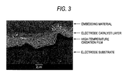
- Fig. 3 is a cross section SEM photograph of the electrode sample of Example 1-7 with a magnification of about 5,000 times.
- a high-temperature oxidation film comprising an oxide of a valve metal or valve metal alloy is formed on the surface of a valve metal or valve metal alloy electrode substrate (hereinafter referred to "valve metal substrate” or “electrode substrate”), the high-temperature oxidation film functioning as an interlayer between the valve metal substrate and an electrode catalyst layer described later, in a single step of only high-temperature oxidation in a substantially oxidative atmosphere.
- a high-temperature oxidation film of an electrode substrate obtained by high-temperature oxidation is rich in corrosion resistance, is minute and is firmly welded to the electrode substrate. Accordingly, the high-temperature oxidation film should protect the electrode substrate and be further able to surely support an electrode catalyst composed mainly of an oxide by means of oxide-oxide linkage.
- the high-temperature oxidation film had a defect that it is inferior in electron conductivity. And when its thickness is increased, this defect became more remarkable.
- the present inventor has solved the above problems by finding that by baking an electrode catalyst layer on this high-temperature oxidation film by the coating thermal decomposition method, even in the high-temperature oxidation film in a region where though an effect for protecting the electrode substrate is large, the electron conductivity is inferior (the increase of weight is 0.5 g/m 2 or more; 1.25 g/m 2 or more as reduced into TiO 2 ), the electron conductivity increases consequently, whereby a large amount of current at the industrial level can be flown.
- the increase of weight is 0.67 g/m 2 or more (1.68 g/m 2 or more as reduced into TiO 2 ), the effect is especially remarkable, and its upper limit is 17 g/m 2 (about 42 g/m 2 as reduced in TiO 2 ).
- the film thickness is 10 ⁇ m or more, the oxidation film turns in color from gray to white, and adhesion between the oxidation film and the electrode substrate is deteriorated.
- the thus formed high-temperature oxidation film is an oxide and is usually inferior in electron conductivity.
- the electron conductivity can be modified, thereby making it possible to flow a large amount of current at the industrial level.
- This heat treatment is performed separately from the heat treatment at the time of forming a high-temperature oxidation film and can be carried out simultaneously with or before or after the formation of an electrode catalyst layer.
- the modification simultaneously with the formation of an electrode catalyst layer means that in the formation of an electrode catalyst layer accompanied with heating as in the coating thermal decomposition method, modification of the high-temperature oxidation film occurs due to the heating at the same time of the formation of an electrode catalyst layer.
- the high-temperature oxidation film (interlayer) is integrated with the electrode substrate, it is never peeled away from the electrode substrate. Further, this high-temperature oxidation film is minute and rich in corrosion resistance. Accordingly, the high-temperature oxidation film sufficiently protects the electrode substrate and is formed as an oxidation film. Thus, the high-temperature oxidation film makes it possible to more surely support the electrode catalyst constituted mainly of an oxide on the electrode substrate by means of oxide-oxide linkage.
- valve metals such as tantalum, niobium, and zirconium and alloys thereof can also be used because modification of a valve metal oxidation film can be achieved.
- the reason why titanium and titanium alloys are preferable resides in not only their corrosion resistance and economy but also the matter that they are large in a ratio of strength to specific gravity, i.e., a specific strength and relatively easy in processing such as rolling, and processing technologies such as cutting are very improved in recent years.
- the shape of the substrate material may be in a simple shape such as the rod-like shape and plate-like shape or may have a complicated shape by means of mechanical processing, and the surface may be either smooth or porous.
- the surface as referred to herein means a portion that when dipped in an electrolyte, can come into contact therewith.
- stains on the substrate surface such as oils and fats, cutting wastes, and salts adversely affect the properties of the high-temperature oxidation film, it is desired that they are previously cleaned and removed as far as possible.
- cleaning examples include alkaline washing, ultrasonic cleaning, steam cleaning, and scrubbing cleaning.
- the welding strength is enhanced so that the electrolytic current density can be substantially reduced.
- cleanliness of the surface increases as compared with mere surface cleaning.
- blasting it is very preferred to perform etching for the purpose of removing blast particles stuck on the surface.
- the etching is carried out using a non-oxidative acid such as hydrochloric acid, sulfuric acid, and oxalic acid or a mixed acid thereof at the boiling point thereof or at a temperature closed to the boiling point, or using nitric-hydrofluoric acid in the vicinity of room temperature.
- the surface is sufficiently dried. It is also possible to rinse the surface with a large amount of tap water before using pure water.
- the electrode substrate is subjected to high-temperature oxidation treatment to form a high-temperature oxidation film on the surface of the electrode substrate.
- the method of forming a high-temperature oxidation film, which is carried out in the present invention is not largely different from annealing to be carried out in air.
- a heating system of a heat treatment furnace systems of atmospheric (convective) heating, direct heating using a nichrome wire or kanthal wire, an infrared ray lamp, a far infrared ray panel, a radiant tube, etc., conductive heating using a hot plate, etc., and electromagnetic induction heating are all employable.
- the heat conductivity of pure titanium at 600°C is small as about one-half of that of pure iron. Accordingly, in order to obtain a uniform temperature distribution as far as possible, a heating system having many convective heating elements is preferable.
- the atmosphere may be oxidative, and in addition to air, oxygen, water vapor, carbon dioxide, and combustion gases such as town gas, gases in which ozone gas is mixed in an inexpensive carrier gas can be employed.
- gases in which ozone gas is mixed in an inexpensive carrier gas can be employed.
- an inert gas such as argon or a vacuum is not effective and improper.
- the substrate having been formed into a prescribed shape and subjected to pre-treatment such as cleaning is inserted in a furnace while hanging by a hanger or placing on a rack.
- pre-treatment such as cleaning
- the feed of an oxidative gas becomes rate-determining, the growth of the oxidation film in the vicinity of the center of the surfaces of the superimposed substrates is delayed, and therefore, such is not preferable.
- the substrate may be inserted into the furnace after raising the temperature of the furnace to a prescribed temperature. However, in order to obtain a uniform temperature distribution, it is desired that the substrate is inserted at a temperature as low as possible, followed by raising the temperature.
- the temperature After arrival at a prescribed temperature, to obtain a high-temperature oxidation film having a fixed thickness, the temperature is held for a prescribed period of time and then reduced.
- the high-temperature oxidation film of titanium observed in the present invention usually has a thickness of 0.1 ⁇ m or more.
- Examples of a method of evaluating the thickness at this level include measurement of an increase of weight, cross section observation by SEM, SIMS, GDS, X-ray diffraction, electron beam diffraction, and ellipsometry. Though each of these methods has merits and demerits, the measurement of an increase of weight is simple and suitable.
- the form of the high-temperature oxidation film interlayer will be described below while focusing the increase of weight that should be an index.
- a value of the surface area expressed by a unit such as mm 2 , cm 2 , and m 2 means (a ⁇ b + b ⁇ c + c ⁇ a) ⁇ 2. So to speak, this value is a surface area corresponding to the shape of the substrate, and in meshes or punching metals, it is approximated by a three-dimensional shape model divided into a polyhedron, a cylinder, etc. Further, it is to be distinguished from a specific surface area by the BET method as calculated from the gas adsorption amount of a single molecular layer.
- the thickness is calculated thicker; when the oxidation film becomes oxygen deficient as compared with the proportioning formulation of TiO 2 , the thickness is calculated thinner; and when oxygen is dissolved in metallic titanium of the substrate, the thickness is calculated thinner.
- influences of the surface roughness of the substrate are largest, and the thickness is liable to be calculated thicker as compared with the measured value by cross section observation.
- titanium alloys are generally suppressed with respect to the growth of a high-temperature oxidation film as compared with pure titanium.
- the oxidation film grows thick.
- the concave part is inversely small in an area where it receives heat radiations or comes into contact with gas, the oxidation film is thin.
- a specular titanium substrate that is smooth and free from roughness is never used as the actual industrial electrolytic substrate.
- the thickness of the high-temperature oxidation film largely varies depending upon unevenness or shape of the surface. Accordingly, it is not proper to define the thickness as a quantitative evaluation method of the high-temperature oxidation film.
- the thickness of a thick portion of the convex part generally reached 0.5-0.7 ⁇ m, and the thickness of a thinnest portion of the concave part was merely about 0.1 ⁇ m.
- the measured value of the increase of weight was 0.67 g/m 2 (0.067 mg/cm 2 ), and the increase of weight as reduced into TiO 2 according to the foregoing calculation express was 1.67 g/m 2 , and the thickness as reduced into rutile type TiO 2 was 0.39 ⁇ m.
- the increase of weight of 0.67 g/m 2 (0.067 mg/cm 2 ) of the high-temperature oxidation film of the titanium substrate formed at a heating temperature of 600°C for a holding time of one hour in air is slightly larger than that described in this literature document. This is because the substrate having a non-smooth surface and having a surface roughness closed to a substrate to be provided for industrial electrolysis is used. Accordingly, in the present invention, the increase of weight of the high-temperature oxidation film interlayer that is essentially effective was defined to be 0.50 g/m 2 (0.050 mg/cm 2 ) or more.
- the weight as reduced into TiO 2 is 1.25 g/m 2
- the thickness as reduced into rutile type TiO 2 is 0.29 ⁇ m.
- a lower limit of the increase of weight may be defined to be 0.67 g/m 2 that is the actual increase of weight.
- An electrode catalyst layer containing a platinum group metal or platinum group metal oxide as the major catalyst is subsequently provided on the thus formed high-temperature oxidation film.
- the platinum group metal or platinum group metal oxide is properly chosen singly or in combination among platinum, ruthenium oxide, iridium oxide, rhodium oxide, palladium oxide, and the like corresponding to a variety of electrolyses. To enhance the adhesion to the substrate or durability against electrolysis, it is desired to mix titanium oxide, tantalum oxide, tin oxide, etc.
- the coating thermal decomposition method As the coating method of this electrode catalyst layer, the coating thermal decomposition method, the sol-gel method, the paste method, the electrophoresis method, the CVD method, and the PVD method, etc. can be employed. Especially, the coating thermal decomposition method described in JP-B-48-3954 and JP-B-46-21888 is suitable.
- iridium oxide rutile type IrO 2
- rutile type IrO 2 rutile type IrO 2
- a peak in the low angle side is broader than that in the high angle side, and therefore, an explicit lattice deformation is observed. It is considered that this deformation is caused by the generation of oxygen-deficient IrO 2-x but not the proportioning formulation of IrO 2 .
- the high-temperature oxidation film of the present invention has both minuteness and adhesion on the surface of the valve metal substrate, a high-temperature oxidation film that is inferior in electron conductivity is formed from the substrate itself.
- oxides of tantalum, niobium, etc. or their mixed oxides with oxides of titanium, tin, etc., as described in JP-B-60-21232 and JP-B-60-22074, which have hitherto been used as an interlayer may be provided on the surface before or after the formation of a high-temperature oxidation film.
- the conventionally proposed conductive interlayers can also be used in combination with the high-temperature oxidation film according to the present invention.
- a high-temperature oxidation film is effectively only in a step of forming a platinum group electrode catalyst layer as shown in Example 1 and Comparative Example 2 described later.
- an interlayer other than such high-temperature oxidation layers having low catalytic activity.
- it is also effective to provide an interlayer simultaneously with or before or after the formation of the high-temperature oxidation film.
- the electrolytic electrode according to the present invention is mainly applied to electrodes for generating oxygen to be exposed under severe conditions during the electrolysis.
- the electrolytic electrode according to the present invention can also be effectively used as electrolytic electrodes for dilute salt water represented by those for hypochlorous acid water having a high rate of occurrence of oxygen generation as a side reaction and for alkaline ionic water/acidic water in which the polarity is reversed and as electrodes for chloride generation having a type of occurrence of corrosion of the electrode substrate depending upon the electrolysis condition.
- Fig. 1 is a schematic view showing one embodiment of an electrolytic electrode according to the present invention.
- an electrolytic electrode 1 made of a valve metal such as titanium or an alloy thereof, the surface of which has been roughed its surface is oxidized by high-temperature heat treatment to form a high-temperature oxidation film 2 made of an oxidation film of the corresponding valve metal oxide. Since this high-temperature oxidation film 2 is integrated with the electrode substrate 1, the high-temperature oxidation film 2 is not peeled away from the electrode substrate 1 and is rich in corrosion resistance, whereby the electrode substrate 1 is surely protected.
- An electrode catalyst 3 containing a metal such as iridium and titanium or a metal oxide thereof as a catalyst is coated and formed on the surface of the high-temperature oxidation film 2.
- An oxide-oxide linkage is formed between the high-temperature oxidation film 2 and the electrode catalyst layer 3 composed mainly of an oxide, thereby surely supporting the electrode catalyst layer 3.
- mercury was used as a contact material.
- mercury was poured into a nickel-made cylindrical container having an inner diameter of 20 mm and a depth of 20 mm.
- a metallic titanium rod having a diameter of 3 mm and a length of 100 mm was subjected to high-temperature oxidation treatment at a prescribed temperature for a prescribed period of time, one end of which was then cut to peel away a high-temperature oxidation film so as to make it possible to flow a current.
- the titanium rod was semi-fixed, and one end where the high-temperature oxidation film remained was immersed in mercury in a length of about 9.9 mm such that the contact area became about 100 mm 2 (1 cm 2 ).
- the " ⁇ cm 2 " unit expresses a resistance value ⁇ corresponding to the unit area cm 2 when a current is flown in the perpendicular direction to the oxidation film. These values are different from a value obtained by measuring the resistance of the oxidation film in the cross section horizontal direction by placing a probe on the surface in the four probe method or the like.
- each of 15 sheets in total of 3 mm-thick titanium plates for general industrial use was roughed by blasting with #20 alumina particles and then cleaned by dipping in boiling 20% hydrochloric acid to prepare 15 sheets in total of electrode substrates.
- the substrate was subjected to temperature rising in air at a rate of about 5°C/min from room temperature.
- the substrate was heat treated at each of the arrival temperatures for a prescribed holding time (see Table 2) and then subjected to furnace cooling to obtain a high-temperature oxidation film of titanium substrate.
- An increase of weight of the high-temperature oxidation film of each substrate (g/m 2 and a value as reduced into mg/cm 2 ) is shown in Table 2 (Examples 1-1 to 1-15).
- a 10% hydrochloric acid mixed solution of iridium chloride containing 70 g/l of iridium and tantalum chloride containing 30 g/l of tantalum was coated on each titanium substrate having such a high-temperature oxidation film formed thereon, dried, and then baked in a muffle furnace kept at 500°C for 10 minutes. This operation was repeated 12 times to prepare an electrode comprising, as an electrode catalyst, a mixed oxide of iridium oxide and tantalum oxide containing about 12 g/m 2 of iridium.
- Each of the electrodes was tested for electrolytic life in 150 g/l of a sulfuric acid aqueous solution of 60°C at a current density 3 A/cm 2 while using a platinum plate as a cathode. At a point of time when the cell voltage increased by 1 V, the life of electrode was judged.
- Fig. 2 also includes the results of Comparative Examples 1-1 and 1-2 in which only the increase of weight by high-temperature oxidation is different.
- the electrolytic life increased in a logarithmic relationship with the increase of weight other than several points present in a peculiar region of 1.5-3.5 g/m 2 in terms of the increase of weight by oxidation (points marked with a circle in Fig. 2).
- This peculiar region is coincident with a region where the color tone of the surface oxidation film changes from pink to gray, and even when the weight increases to 3.5 g/m 2 or more, the color tone does not change.
- This is considered to be a special phenomenon occurred in a transition region where the optical semiconductor characteristic of the surface oxidation film largely changes, but such is theoretically unclear.
- FIG. 3 A cross section SEM photograph of the electrode sample of Example 1-7 with a magnification of about 5,000 times is shown in Fig. 3.
- Samples were prepared in the same manner as in Example 1, except that the heat treatment was carried out at an arrival temperature of 500°C for a holding time of one hour (Comparative Example 1-1) and at an arrival temperature of 500°C for a holding time of 3 hours (Comparative Example 1-2), respectively, followed by performing furnace cooling to obtain high-temperature oxidation films of titanium substrate, and then subjected to test for electrolytic life.
- the increase of weight was 0.18 g/m 2 in Comparative Example 1-1 and 0.30 g/m 2 in Comparative Example 1-2, respectively.
- the high-temperature is effective only when it is carried out as the pre-treatment of the substrate. Besides, it is considered that the timing of heat treatment may be during the formation of the electrode catalyst layer or after the formation of the electrode catalyst layer.
- the role of the high-temperature oxidation step was examined by comparing the usefulness.
- An electrode substrate obtained by roughing and cleaning in the same manner as in Example 1 was coated directly with a 10% hydrochloric acid mixed solution of iridium chloride containing 70 g/l of iridium and tantalum chloride containing 30 g/l of tantalum without forming a high-temperature oxidation film, dried, and then baked in a muffle furnace kept at 500°C (Comparative Example 2-1), 550°C (Comparative Example 2-2), 600°C (Comparative Example 2-3) and 650°C (Comparative Example 2-4), respectively for 10 minutes. This operation was repeated 12 times to prepare an electrode comprising, as an electrode catalyst, a mixed oxide of iridium oxide and tantalum oxide containing about 12 g/m 2 of iridium.
- one sample was taken from the electrode samples baked at 500°C, heat treated in the same procedures for obtaining a high-temperature oxidation film of titanium substrate by raising the temperature at a rate of about 5°C/min from room temperature and setting up an arrival temperature at 650°C and a holding time at 3 hours (Comparative Example 2-5), and then subjected to furnace cooling.
- the heat treatment after the formation of this electrode catalyst layer is hereinafter referred to as "post baking".
- Each of the electrodes was tested for electrolytic life in 150 g/l of a sulfuric acid aqueous solution of 60°C at a current density 3 A/cm 2 while using a platinum plate as a cathode. At a point of time when the cell voltage increased by 1 V, the life of electrode was judged.
- each of 8 sheets in total of 3 mm-thick titanium plates for general industrial use was roughed by blasting with #20 alumina particles and then cleaned by dipping in boiling 20% hydrochloric acid to prepare electrode substrates (Examples 2-1 to 2-8).
- each of the six sheets of electrode substrates of Examples 2-1 to 2-6 was coated once with a 10% hydrochloric acid solution of tantalum chloride TaCl 5 containing 10 g/l of tantalum as a coating solution for forming a high-temperature oxidation film described in Example 1 of JP-B-60-21232.
- the resulting substrate was subjected to temperature rising in air at a rate of about 5°C/min from room temperature, heat treated under a prescribed condition shown in Table 3, and then subjected to furnace cooling, to obtain a high-temperature oxidation film on the titanium substrate.
- each of the two sheets of electrode substrates of Examples 2-7 and 2-8 was coated once with a 10% hydrochloric acid solution of molybdenum chloride MoCl 5 containing 10 g/l of molybdenum as a coating solution for forming a high-temperature oxidation film.
- the resulting substrate was subjected to temperature rising in air at a rate of about 5°C/min from room temperature, heat treated at an arrival temperature of 650°C for a holding time of 45 minutes or 3 hours, and then subjected to furnace cooling, to obtain a high-temperature oxidation film on the titanium substrate.
- a 10% hydrochloric acid mixed solution of iridium chloride containing 70 g/l of iridium and tantalum chloride containing 30 g/l of tantalum was coated on the titanium substrate having such a high-temperature oxidation film formed thereon, dried, and then baked in a muffle furnace kept at 500°C for 10 minutes. This operation was repeated 12 times to prepare 8 sheets in total of electrodes each comprising, as an electrode catalyst, a mixed oxide of iridium oxide and tantalum oxide containing about 12 g/m 2 of iridium.
- Each of the electrodes was tested for electrolytic life in 150 g/l of a sulfuric acid aqueous solution of 60°C at a current density 3 A/cm 2 while using a platinum plate as a cathode. At a point of time when the cell voltage increased by 1 V, the life of electrode was judged. The life of each of the electrodes is shown in Table 3.
- Examples 2-1 to 2-6 in which after coating tantalum chloride, high-temperature oxidation was carried out, there is seen a tendency that the electrolytic life was prolonged as compared with that of the high-temperature oxidation film prepared by only high-temperature oxidation.
- These examples are an example in which corrosion resistance of tantalum oxide is added to the high-temperature oxidation film, namely an additive or synergistic effect is observed.
- the resulting tantalum oxide had a net weight of about 0.05 g/m 2
- the increase of weight after coating of tantalum chloride and subsequent high-temperature oxidation was inversely smaller than the increase of weight of the high-temperature oxidation film of the simple titanium substrate. It is estimated that the oxidation of the titanium substrate was suppressed by the tantalum oxide.
- the molybdenum oxide it is considered that though the molybdenum oxide was vaporized during the high-temperature oxidation at 650°C or higher, it played the same action during a time when it remained.
- Samples were prepared in the same manner as in Example 2, except that after coating the coating solution and drying, the heat treatment was carried out at an arrival temperature of 500°C for a holding time of 10 minutes, followed by furnace cooling to obtain high-temperature oxidation films of titanium substrate, and then subjected to test for electrolytic life.
- Comparative Example 3-1 after coating tantalum chloride, the sample was subjected to heat oxidation
- Comparative Example 3-2 after coating molybdenum chloride, the sample was subjected to heat oxidation.
- the increase of weight of the titanium substrate in Comparative Example 3-1 was 0.07 g/m 2
- the increase of weight of the titanium substrate in Comparative Example 3-2 was 0.08 g/m 2 .
- the cell voltage rapidly increased within a short period of time.
- One of these substrates was injected with a Ta ion at injection energy of 45 keV in an injection amount of 1 ⁇ 10 16 ions/cm 2 (Example 3-1); and another substrate was injected with a Ta ion at injection energy of 45 keV in an injection amount of 1 x 10 17 ions/cm 2 (Example 3-2).
- Still another substrate was subjected by composite ion injection of Ta and Ni by injecting first with a Ta ion at injection energy of 45 keV in an injection amount of 1 ⁇ 10 17 ions/cm 2 and then with an Ni ion at injection energy of 50 keV in an injection amount of 5 ⁇ 10 16 ions/cm 2 (Example 3-3).
- these three sheets of substrates were subjected to temperature rise in air at a rate of about 5°C/min from room temperature and heated treated at an arrival temperature of 650 °C for a holding time of 3 hours, followed by furnace cooling to obtain high-temperature oxidation films of titanium substrate.
- the increase of weight of the titanium substrate was 2.79 g/m 2 (Example 3-1), 2.36 g/m 2 (Example 3-2) and 2.34 g/m 2 (Example 3-3), respectively.
- A10 % hydrochloric acid mixed solution of iridium chloride containing 70 g/l of iridium and tantalum chloride containing 30 g/l of tantalum was coated on the titanium substrate having such a high-temperature oxidation film formed thereon, dried, and then baked in a muffle furnace kept at 500°C for 10 minutes. This operation was repeated 12 times to prepare electrodes each comprising, as an electrode catalyst, a mixed oxide of iridium oxide and tantalum oxide containing about 12 g/m 2 of iridium.
- Each of the electrodes was tested for electrolytic life in 150 g/l of a sulfuric acid aqueous solution of 60°C at a current density 3 A/cm 2 while using a platinum plate as a cathode. At a point of time when the cell voltage increased by 1 V, the life of electrode was judged.
- Example 3-1 and Comparative Example 4-1 in which the amount of the Ta ion is low, the high-temperature oxidation treatment was very largely effective.
- Example 3-2 and Comparative Example 4-2 when the amount of the Ta ion is high, and a sufficient electrolytic life could be originally obtained even by not subjecting to high-temperature oxidation, its effect was limitative or additive.
- NiTiO 3 that is also inferior in corrosion resistance by high-temperature oxidation, leading to a large expansion of the life by the high-temperature treatment. It is considered that NiTiO 3 that is present in the fine granular state is included in the high-temperature oxidation film and isolated, whereby adverse influences are suppressed. That is one of the effects of the high-temperature oxidation film.
- Samples were prepared in the same manners as in Examples 3-1 to 3-3, except that the substrates after the ion injection of Examples 3-1 to 3-3 were each coated with an electrode catalyst as it was without carrying out high-temperature oxidation as the post treatment, and then subjected to test for electrolytic life (Comparative Examples 4-1, 4-2 and 4-3 in order).
- the present invention relates to an electrolytic electrode comprising a valve metal or valve metal alloy electrode substrate, a high-temperature oxidation film formed on the surface of the valve metal or valve metal alloy electrode by high-temperature oxidation treatment such that an increase of weight is 0.5 g/m 2 or more, and preferably 0.67 g/m 2 or more, and an electrode catalyst layer formed on the surface of the high-temperature oxidation film and to a process of producing the same.
- valve metal valve metal alloy electrode substrate By heat treating a valve metal valve metal alloy electrode substrate in an oxidative atmosphere to form a high-temperature oxidation film having an increase of weight of 0.5 g/m 2 or more, or 1.25 g/m 2 or more as reduced into TiO 2 , which is inferior in electron conductivity, and further baking an electrode catalyst layer on the high-temperature oxidation film by the coating thermal decomposition method, the electron conductivity can be consequently increased to obtain an electrolytic electrode capable of flowing a large amount of current at the industrial level.
- This high-temperature oxidation film is rich in corrosion resistance, is minute and is firmly welded to the electrode substrate. Accordingly, the high-temperature oxidation film can protect the electrode substrate from a corrosive electrolyte and electrolytic reaction and surely support an electrode catalyst by means of oxide-oxide welding. Thus, the electrode catalyst in the catalyst layer can be effectively applied.
Abstract
Description
- The present invention relates to an electrolytic electrode that is used in various industrial electrolyses, and a process of producing the same. In more detail, the present invention relates to an anode for generating oxygen, which is used in the industrial electrolysis for electrolytic copper foil manufacture, aluminum in-liquid power feed, and continuous electrolytic zinc-coated carbon steel sheet manufacture, and the like, and a process of producing the same.
- In recent years, in the industrial electrolysis for electrolytic copper foil manufacture, aluminum in-liquid power feed, and continuous electrolytic zinc-coated carbon steel sheet manufacture, and the like, anodes composed mainly of a metallic titanium substrate coated with iridium oxide as an electrode catalyst have been frequently employed. However, since anodes for generating chlorine, which are used in the electrolysis of salt and composed mainly of ruthenium oxide as an electrode catalyst, have a direct bearing on the purity of chlorine and sodium hydroxide products, the management of an electrolytic bath is exhaustive, and it is rare that impurities likely hastening consumption of the electrode catalyst mingle into the electrolytic bath. On the other hand, in the industrial electrolysis for producing a product with added value mainly in a cathode, organic materials or impurity elements are added for the purpose of stabilizing the product. For this reason, in the vicinity of the anode where the generation of oxygen is performed in the diaphragm-free state, various electrochemical reactions or chemical reactions occur, thereby further hastening the consumption of the electrode catalyst due to an increase of the hydrogen ion concentration (a lowering of pH) following the generation reaction of oxygen.
- The ruthenium oxide electrode catalyst that is usually used for the generation of chlorine can be used to and extent of about 90% of the catalyst-supporting amount. On the other hand, the iridium oxide electrode catalyst that is frequently used for the generation of oxygen can be used to an extent of only about 50%, and the electrode potential increases in that state, whereby the electrolysis may often become impossible.
- The potential increase of the electrode for generating oxygen is started from the consumption of the electrode catalyst and corrosion of the electrode substrate generated due to the common cause. Further, it is considered that because of partial internal consumption and peeling of the electrode catalyst, current convergence to the residual electrode catalyst is added, whereby the potential increase advances in the chained and accelerated way.
- To suppress corrosive dissolution of the electrode substrate and accompany peeling of the effective electrode catalyst from the electrode catalyst, there are employed a lot of methods represented by a method of providing an interlayer (high-temperature oxidation film) between a titanium substrate and an electrode catalyst layer.
- In general, as the interlayer, those having an electrode activity lower than the electrode catalyst layer are chosen, and any of these types have electron conductivity and have a role such that by making the electrode substrate far from a corrosive electrolyte and an oxygen-generating side resulting in a lowering of pH, the damage of the substrate is relieved.
- As the interlayer that can meet these requirements, JP-B-60-21232 proposes an interlayer in which an oxide of tantalum and/or niobium is provided in a thickness of 0.001-1 g/m2 as reduced into a metal, and electroconductivity is imparted to a titanium oxide film formed on the substrate surface. Further, JP-B-60-22074 proposes a valency-controlled semiconductor comprising an oxide of titanium and/or tin having an oxide of tantalum and/or niobium added thereto. Both of them are widely used on an industrial scale. However, in recent years, in view of the trend of attaching importance to the economical efficiency, the operation condition becomes severe more or more, and electrodes having higher durability are required.
- As a simple and practically useful measure, there is the case of increasing the coating amount of the electrode catalyst. However, it is not always the case that the coating amount is in direct proportion to the electrode life. In the severe circumstance as described previously, since deterioration also advances in the vicinity of the interface between the electrode substrate and the electrode catalyst, all of the increased electrode catalyst is not always effectively utilized. As a result, the precious electrode catalyst will be wasted.
- To overcome the problems in forming such an interlayer, a method in which a titanium-made electrode substrate itself is electrolytically oxidized to convert titanium on the surface of the electrode substrate to titanium oxide, thereby forming an interlayer (titanium oxide single layer) is described in JP-A-7-90665. However, in the electrode described in this publication, since the interlayer that can be formed by electrolytic oxidation is extremely thin, sufficient corrosion resistance is not obtained. For this reason, a thick titanium oxide second single layer is formed on the surface of the foregoing first titanium oxide single layer by the thermal decomposition method, on which is then formed an electrode catalyst layer. Incidentally, though it is also disclosed to form the first titanium oxide single layer upon heating in an oxygen-containing atmosphere, even in this case, the second titanium oxide single layer is formed.
- According to the method described in JP-A-7-90665, since the formation of an interlayer requires two steps, especially steps requiring equipment quite different from each other as in electrolysis and thermal decomposition, the workability is inferior, and economical loads are large. Therefore, this method could not have sufficient practical usefulness.
- The present invention has been made in view of the above disadvantages of the conventional techniques.
- Accordingly, one object of the present invention is to provide an electrolytic electrode in which an interlayer (high-temperature oxidation film) that is rich in corrosion resistance, is minute, can be firmly welded to an electrode substrate and can be prepared in a single step is formed midway between an electrode substrate and an electrode catalyst.
- Another object of the present invention is to provide processes of producing the electrolytic electrode.
- The electrolytic electrode according to the present invention comprises:
- a valve metal or valve metal alloy electrode substrate,
- a high-temperature oxidation film formed on the surface of the valve metal or valve metal alloy electrode by high-temperature oxidation treatment such that an increase of weight is 0.5 g/m2 or more, and
- an electrode catalyst layer formed on the surface of the high-temperature oxidation film.
-
- A process of producing an electrolytic electrode according to a first embodiment of the present invention comprises:
- forming a high-temperature oxidation film on the surface of a valve metal or valve metal alloy electrode by high-temperature oxidation treatment such that its increase of weight is 0.5 g/m2 or more (1.25 g/m2 or more as reduced into TiO2), and
- forming an electrode catalyst layer on the high-temperature oxidation film.
-
- A process of producing an electrolytic electrode according to a second embodiment of the present invention comprises:
- forming a high-temperature oxidation film on the surface of a valve metal or valve metal alloy electrode by high-temperature oxidation treatment, and
- forming an electrode catalyst layer on the high-temperature oxidation film, wherein in forming the high-temperature oxidation film, an increase of weight of the high-temperature oxidation film is at least an increase of weight of a high-temperature oxidation film of a valve metal or valve metal alloy electrode substrate formed at a heating temperature of 600°C for a holding time of one hour in air.
-
-
- Fig. 1 is a conceptional view showing one embodiment of an electrolytic electrode according to the present invention.
- Fig. 2 is a graph showing the relationship between the increase of weight of the high-temperature oxidation film and the electrolytic life obtained in the Examples and
-
- Fig. 3 is a cross section SEM photograph of the electrode sample of Example 1-7 with a magnification of about 5,000 times.
- In the drawings:
- 1: Electrode substrate
- 2: Interlayer
- 3: Electrode catalyst layer
-
- The present invention will be described below in detail.
- Different from the conventional techniques, according to the present invention, a high-temperature oxidation film comprising an oxide of a valve metal or valve metal alloy is formed on the surface of a valve metal or valve metal alloy electrode substrate (hereinafter referred to "valve metal substrate" or "electrode substrate"), the high-temperature oxidation film functioning as an interlayer between the valve metal substrate and an electrode catalyst layer described later, in a single step of only high-temperature oxidation in a substantially oxidative atmosphere.
- A high-temperature oxidation film of an electrode substrate obtained by high-temperature oxidation is rich in corrosion resistance, is minute and is firmly welded to the electrode substrate. Accordingly, the high-temperature oxidation film should protect the electrode substrate and be further able to surely support an electrode catalyst composed mainly of an oxide by means of oxide-oxide linkage. However, actually, the high-temperature oxidation film had a defect that it is inferior in electron conductivity. And when its thickness is increased, this defect became more remarkable.
- The present inventor has solved the above problems by finding that by baking an electrode catalyst layer on this high-temperature oxidation film by the coating thermal decomposition method, even in the high-temperature oxidation film in a region where though an effect for protecting the electrode substrate is large, the electron conductivity is inferior (the increase of weight is 0.5 g/m2 or more; 1.25 g/m2 or more as reduced into TiO2), the electron conductivity increases consequently, whereby a large amount of current at the industrial level can be flown. When the increase of weight is 0.67 g/m2 or more (1.68 g/m2 or more as reduced into TiO2), the effect is especially remarkable, and its upper limit is 17 g/m2 (about 42 g/m2 as reduced in TiO2). When the increase of weight exceeds this upper limit, the film thickness is 10 µm or more, the oxidation film turns in color from gray to white, and adhesion between the oxidation film and the electrode substrate is deteriorated.
- That is, the thus formed high-temperature oxidation film is an oxide and is usually inferior in electron conductivity. When after forming the high-temperature oxidation film, it is heat treated at a high temperature of 300°C or higher, the electron conductivity can be modified, thereby making it possible to flow a large amount of current at the industrial level. This heat treatment is performed separately from the heat treatment at the time of forming a high-temperature oxidation film and can be carried out simultaneously with or before or after the formation of an electrode catalyst layer. The modification simultaneously with the formation of an electrode catalyst layer means that in the formation of an electrode catalyst layer accompanied with heating as in the coating thermal decomposition method, modification of the high-temperature oxidation film occurs due to the heating at the same time of the formation of an electrode catalyst layer.
- Since the thus formed high-temperature oxidation film (interlayer) is integrated with the electrode substrate, it is never peeled away from the electrode substrate. Further, this high-temperature oxidation film is minute and rich in corrosion resistance. Accordingly, the high-temperature oxidation film sufficiently protects the electrode substrate and is formed as an oxidation film. Thus, the high-temperature oxidation film makes it possible to more surely support the electrode catalyst constituted mainly of an oxide on the electrode substrate by means of oxide-oxide linkage.
- In the present invention, as the substrate material, though titanium and titanium alloys can be preferably used, so-called valve metals such as tantalum, niobium, and zirconium and alloys thereof can also be used because modification of a valve metal oxidation film can be achieved. The reason why titanium and titanium alloys are preferable resides in not only their corrosion resistance and economy but also the matter that they are large in a ratio of strength to specific gravity, i.e., a specific strength and relatively easy in processing such as rolling, and processing technologies such as cutting are very improved in recent years. The shape of the substrate material may be in a simple shape such as the rod-like shape and plate-like shape or may have a complicated shape by means of mechanical processing, and the surface may be either smooth or porous. The surface as referred to herein means a portion that when dipped in an electrolyte, can come into contact therewith.
- Since stains on the substrate surface, such as oils and fats, cutting wastes, and salts adversely affect the properties of the high-temperature oxidation film, it is desired that they are previously cleaned and removed as far as possible. Examples of cleaning that can be employed include alkaline washing, ultrasonic cleaning, steam cleaning, and scrubbing cleaning.
- By roughing the surface by blasting or etching to enlarge the surface area, the welding strength is enhanced so that the electrolytic current density can be substantially reduced. By carrying out etching, cleanliness of the surface increases as compared with mere surface cleaning. In the case of blasting, it is very preferred to perform etching for the purpose of removing blast particles stuck on the surface. The etching is carried out using a non-oxidative acid such as hydrochloric acid, sulfuric acid, and oxalic acid or a mixed acid thereof at the boiling point thereof or at a temperature closed to the boiling point, or using nitric-hydrofluoric acid in the vicinity of room temperature.
- As finishing, after rinsing the surface with pure water, the surface is sufficiently dried. It is also possible to rinse the surface with a large amount of tap water before using pure water.
- The electrode substrate is subjected to high-temperature oxidation treatment to form a high-temperature oxidation film on the surface of the electrode substrate.
- Basically speaking, the method of forming a high-temperature oxidation film, which is carried out in the present invention, is not largely different from annealing to be carried out in air.
- As a heating system of a heat treatment furnace, systems of atmospheric (convective) heating, direct heating using a nichrome wire or kanthal wire, an infrared ray lamp, a far infrared ray panel, a radiant tube, etc., conductive heating using a hot plate, etc., and electromagnetic induction heating are all employable. For example, the heat conductivity of pure titanium at 600°C is small as about one-half of that of pure iron. Accordingly, in order to obtain a uniform temperature distribution as far as possible, a heating system having many convective heating elements is preferable. The atmosphere may be oxidative, and in addition to air, oxygen, water vapor, carbon dioxide, and combustion gases such as town gas, gases in which ozone gas is mixed in an inexpensive carrier gas can be employed. When hydrogen gas or an ammonia decomposition gas containing hydrogen gas is mixed, titanium or an titanium alloy is hydrogenated, thereby embrittling even the deepest part, and therefore, it is desired to avoid such usage. Needless to say, an inert gas such as argon or a vacuum is not effective and improper.
- The substrate having been formed into a prescribed shape and subjected to pre-treatment such as cleaning is inserted in a furnace while hanging by a hanger or placing on a rack. In all of the cases, attention must be paid such that a plurality of substrates do not come into intimate contact with each other, but renewal of a substrate to be brought into contact with the substrate is carried out without delay. When the feed of an oxidative gas becomes rate-determining, the growth of the oxidation film in the vicinity of the center of the surfaces of the superimposed substrates is delayed, and therefore, such is not preferable.
- The substrate may be inserted into the furnace after raising the temperature of the furnace to a prescribed temperature. However, in order to obtain a uniform temperature distribution, it is desired that the substrate is inserted at a temperature as low as possible, followed by raising the temperature.
- After arrival at a prescribed temperature, to obtain a high-temperature oxidation film having a fixed thickness, the temperature is held for a prescribed period of time and then reduced.
- The high-temperature oxidation film of titanium observed in the present invention usually has a thickness of 0.1 µm or more. Examples of a method of evaluating the thickness at this level include measurement of an increase of weight, cross section observation by SEM, SIMS, GDS, X-ray diffraction, electron beam diffraction, and ellipsometry. Though each of these methods has merits and demerits, the measurement of an increase of weight is simple and suitable.
- The form of the high-temperature oxidation film interlayer will be described below while focusing the increase of weight that should be an index.
- In the present invention, for example, in the case of a rectangular parallelepiped with three sides a, b and c, a value of the surface area expressed by a unit such as mm2, cm2, and m2 means (a × b + b × c + c × a) × 2. So to speak, this value is a surface area corresponding to the shape of the substrate, and in meshes or punching metals, it is approximated by a three-dimensional shape model divided into a polyhedron, a cylinder, etc. Further, it is to be distinguished from a specific surface area by the BET method as calculated from the gas adsorption amount of a single molecular layer.
- When an increase of weight by means of high-temperature oxidation is defined as ΔW (g/m2), and O and Ti are defined as 16.00 and 47.88, respectively, the weight WTiO2 (g/m2) of a high-temperature oxidation film of titanium is calculated as follows.
- Further, since only TiO2 of a rutile phase is detected from identification of a crystal phase by the X-ray diffraction of the high-temperature oxidation film of titanium, when the density of TiO2 of the rutile phase is defined as 4.27 g/ml, the thickness t (µm) is calculated as follows.
- The larger the surface roughness of the substrate, the larger the actual surface area is, and thus, the increase of weight becomes large. Accordingly, the reduced value into the thickness is calculated thicker; when the oxidation film becomes oxygen deficient as compared with the proportioning formulation of TiO2, the thickness is calculated thinner; and when oxygen is dissolved in metallic titanium of the substrate, the thickness is calculated thinner. Actually, influences of the surface roughness of the substrate are largest, and the thickness is liable to be calculated thicker as compared with the measured value by cross section observation.
- Also, titanium alloys are generally suppressed with respect to the growth of a high-temperature oxidation film as compared with pure titanium.
- Since the convex part of the actual surface roughness by the cross section observation is large in an area where it receives heat radiations or comes into contact with gas, the oxidation film grows thick. On the other hand, since the concave part is inversely small in an area where it receives heat radiations or comes into contact with gas, the oxidation film is thin. A specular titanium substrate that is smooth and free from roughness is never used as the actual industrial electrolytic substrate. Further, the thickness of the high-temperature oxidation film largely varies depending upon unevenness or shape of the surface. Accordingly, it is not proper to define the thickness as a quantitative evaluation method of the high-temperature oxidation film.
- For example, according to the measured values on a cross section SEM photograph when a high-temperature oxidation film was formed using a titanium substrate having a surface roughness Ra of 12.5 µm in air at a heating temperature of 600°C for a holding time of one hour, the thickness of a thick portion of the convex part generally reached 0.5-0.7 µm, and the thickness of a thinnest portion of the concave part was merely about 0.1 µm. Incidentally, at this time, the measured value of the increase of weight was 0.67 g/m2 (0.067 mg/cm2), and the increase of weight as reduced into TiO2 according to the foregoing calculation express was 1.67 g/m2, and the thickness as reduced into rutile type TiO2 was 0.39 µm.
- With respect to the increase of weight of a high-temperature oxidation film of pure titanium in air, some literature documents are known. In one of them, from a rate constant Kp = 33.46 × 10⁻⁴ (40 hours or shorter) of high-temperature oxidation of pure titanium in air at 600°C, an increase of weight of a high-temperature oxidation film at 600°C for one hour is calculated to be 0.058 mg/cm2 (A.M. Chaze and C. Coddet, Oxidation of Metals, Vol. 27, Nos. 1/2, 1-20 (1987)).
- The increase of weight of 0.67 g/m2 (0.067 mg/cm2) of the high-temperature oxidation film of the titanium substrate formed at a heating temperature of 600°C for a holding time of one hour in air is slightly larger than that described in this literature document. This is because the substrate having a non-smooth surface and having a surface roughness closed to a substrate to be provided for industrial electrolysis is used. Accordingly, in the present invention, the increase of weight of the high-temperature oxidation film interlayer that is essentially effective was defined to be 0.50 g/m2 (0.050 mg/cm2) or more. At this time, the weight as reduced into TiO2 is 1.25 g/m2, and the thickness as reduced into rutile type TiO2 is 0.29 µm. A lower limit of the increase of weight may be defined to be 0.67 g/m2 that is the actual increase of weight.
- An electrode catalyst layer containing a platinum group metal or platinum group metal oxide as the major catalyst is subsequently provided on the thus formed high-temperature oxidation film. The platinum group metal or platinum group metal oxide is properly chosen singly or in combination among platinum, ruthenium oxide, iridium oxide, rhodium oxide, palladium oxide, and the like corresponding to a variety of electrolyses. To enhance the adhesion to the substrate or durability against electrolysis, it is desired to mix titanium oxide, tantalum oxide, tin oxide, etc.
- As the coating method of this electrode catalyst layer, the coating thermal decomposition method, the sol-gel method, the paste method, the electrophoresis method, the CVD method, and the PVD method, etc. can be employed. Especially, the coating thermal decomposition method described in JP-B-48-3954 and JP-B-46-21888 is suitable.
- The reason why when heat treatment is carried out simultaneously with or before or after the formation of an electrode catalyst layer of the electrolytic electrode of the present invention, the electron conductivity of the high-temperature oxidation film that is inferior in electron conductivity increases is not always theoretically clear, it may be assumed based on some proper estimations as follows.
- In general, when adjacent two phases are in the equilibrium state, a principle that the chemical potential of the respective components is identical in all of the phases. That is, when the two adjacent phases containing oxygen are in the equilibrium state at the interface, the chemical potential of oxygen should be continued at the interface of the two phases. In order that the whole of the two phases achieves the equilibrium, diffusion of oxygen over a long distance is necessary. However, it is said that in order to achieve local equilibrium at the interface, diffusion of only about several angstroms may be required (Paul G Shewmon, Diffusion in Solids, translated by Kazuo Fueki and Koichi Kitazawa and published by Corona Publishing Co., Ltd., p.148 (1976)).
- It is considered that with respect to the oxygen concentration profile of the high-temperature oxidation film of titanium and titanium alloy in the depth direction, in view of the mechanism that oxygen is diffused from the substrate surface to the inside of the substrate, the oxygen concentration is naturally highest in the outermost surface layer, and in the outermost surface layer of the high-temperature oxidation film that is inferior in electron conductivity, the formulation is closed to the proportioning formulation of TiO2.
- With respect to the electrode catalyst layer, for example, iridium oxide (rutile type IrO2) that is most often used for the generation of oxygen, in the X-ray diffraction pattern, a peak in the low angle side is broader than that in the high angle side, and therefore, an explicit lattice deformation is observed. It is considered that this deformation is caused by the generation of oxygen-deficient IrO2-x but not the proportioning formulation of IrO2.
- Accordingly, it is estimated that the chemical potential of oxygen becomes closed to the equilibrium at the interface of the two phases of the high-temperature oxidation film and the electrode catalyst layer in the state that oxygen of the surface of the high-temperature oxidation film is diffused into the electrode catalyst layer during the heat treatment of the electrode catalyst layer. Since in metallic platinum, its outermost surface layer is made of platinum oxide, it may be considered that the same phenomenon occurs as in other platinum group metal oxides.
- Although the high-temperature oxidation film of the present invention has both minuteness and adhesion on the surface of the valve metal substrate, a high-temperature oxidation film that is inferior in electron conductivity is formed from the substrate itself. In this regard, oxides of tantalum, niobium, etc. or their mixed oxides with oxides of titanium, tin, etc., as described in JP-B-60-21232 and JP-B-60-22074, which have hitherto been used as an interlayer, may be provided on the surface before or after the formation of a high-temperature oxidation film. Besides, the conventionally proposed conductive interlayers can also be used in combination with the high-temperature oxidation film according to the present invention.
- The formation of a high-temperature oxidation film is effectively only in a step of forming a platinum group electrode catalyst layer as shown in Example 1 and Comparative Example 2 described later. There is no limitation with respect to the formation of an interlayer other than such high-temperature oxidation layers having low catalytic activity. As shown in Example 2 and Example 3, it is also effective to provide an interlayer simultaneously with or before or after the formation of the high-temperature oxidation film.
- The electrolytic electrode according to the present invention is mainly applied to electrodes for generating oxygen to be exposed under severe conditions during the electrolysis. The electrolytic electrode according to the present invention can also be effectively used as electrolytic electrodes for dilute salt water represented by those for hypochlorous acid water having a high rate of occurrence of oxygen generation as a side reaction and for alkaline ionic water/acidic water in which the polarity is reversed and as electrodes for chloride generation having a type of occurrence of corrosion of the electrode substrate depending upon the electrolysis condition.
- Fig. 1 is a schematic view showing one embodiment of an electrolytic electrode according to the present invention.
- In an
electrolytic electrode 1 made of a valve metal such as titanium or an alloy thereof, the surface of which has been roughed, its surface is oxidized by high-temperature heat treatment to form a high-temperature oxidation film 2 made of an oxidation film of the corresponding valve metal oxide. Since this high-temperature oxidation film 2 is integrated with theelectrode substrate 1, the high-temperature oxidation film 2 is not peeled away from theelectrode substrate 1 and is rich in corrosion resistance, whereby theelectrode substrate 1 is surely protected. - An electrode catalyst 3 containing a metal such as iridium and titanium or a metal oxide thereof as a catalyst is coated and formed on the surface of the high-
temperature oxidation film 2. When the formation of the electrode catalyst layer 3 is carried out under heating conditions, or the whole of the electrode after forming the electrode catalyst layer 3 is heated, modification occurs at the interface between the high-temperature oxidation film 2 and the electrode catalyst layer 3, thereby imparting electron conductivity to the high-temperature oxidation film 2 that is originally non-electron conductive. Thus, it becomes possible to flow a large amount of current at the industrial electrolysis level. - An oxide-oxide linkage is formed between the high-
temperature oxidation film 2 and the electrode catalyst layer 3 composed mainly of an oxide, thereby surely supporting the electrode catalyst layer 3. - When a valve metal is contained in the electrode catalyst layer 3, a firmer linkage is formed between the valve metal in the high-
temperature oxidation film 2 and the valve metal in the electrode catalyst layer 3, whereby the durability is sufficiently enhanced. - An example of measuring the contact resistance value of an actual high-temperature oxidation film of metallic titanium will be described below as Referential Example of the present invention.
- To avoid abrasion or dropping of the oxidation film due to strong contact or generation of an error due to partial contact, mercury was used as a contact material.
- First of all, mercury was poured into a nickel-made cylindrical container having an inner diameter of 20 mm and a depth of 20 mm. A metallic titanium rod having a diameter of 3 mm and a length of 100 mm was subjected to high-temperature oxidation treatment at a prescribed temperature for a prescribed period of time, one end of which was then cut to peel away a high-temperature oxidation film so as to make it possible to flow a current. The titanium rod was semi-fixed, and one end where the high-temperature oxidation film remained was immersed in mercury in a length of about 9.9 mm such that the contact area became about 100 mm2 (1 cm2). A prescribed value of a current was flown while setting the titanium rod side as plus and the nickel container side as minus, and a voltage between the titanium rod and the nickel container was measured and reduced into a resistance value. The results (measured values of contact resistance of the high-temperature oxidation film) are shown in Table 1.
- In the table, the "Ωcm2" unit expresses a resistance value Ω corresponding to the unit area cm2 when a current is flown in the perpendicular direction to the oxidation film. These values are different from a value obtained by measuring the resistance of the oxidation film in the cross section horizontal direction by placing a probe on the surface in the four probe method or the like.
Measured values of contact resistance of high-temperature oxidation film Current value (A/cm2) Film resistance (in the vertical direction) (Ωcm2) High-temperature oxidation treatment condition At 500°C for one hour At 500°C for 3 hours At 600°C for one hour At 600°C for 3 hours At 650°C for one hour At 650 °C for 3 hours 0.0095 - - - - 16.419 0.0165 - - - - - 15.931 0.0330 - - - - - 14.367 0.0427 - - - - 2.308 - 0.0495 - - - - - 13.789 0.0500 0.078 0.316 0.624 0.700 - - 0.0828 - - - - 2.195 - 0.1000 0.063 0.316 0.620 0.670 - - 0.1233 - - - - 2.181 - 0.1500 0.068 0.295 0.593 0.687 - - 0.1562 - - - - 2.626 - 0.2000 0.070 0.264 0.560 0.670 - - Average 0.070 0.298 0.599 0.682 2.327 15.126 - If a current of 3 A/cm2 as in this Example were flown into the oxidation film layers having an average film resistance of 0.070, 0.298, 0.599, 0.682, 2.327 and 15.126 Ωcm2 in Table 1, respectively, an increase of voltage of 0.2, 0.9, 1.8, 2.0, 7.0 and 45.5 V should have been originally generated, respectively. However, when each electrode was actually provided for electrolysis after forming an electrode catalyst layer by the thermal decomposition method, all of the electrodes exhibited a standardized cell voltage as high as about 4.5 V, so that there was observed no difference.
- Examples and Comparative Examples with respect to the electrolytic electrode according to the present invention along with the process of producing the same will be described below, but it should not be construed that the present invention is limited thereto.
- The surface of each of 15 sheets in total of 3 mm-thick titanium plates for general industrial use was roughed by blasting with #20 alumina particles and then cleaned by dipping in boiling 20% hydrochloric acid to prepare 15 sheets in total of electrode substrates. The substrate was subjected to temperature rising in air at a rate of about 5°C/min from room temperature. The substrate was heat treated at each of the arrival temperatures for a prescribed holding time (see Table 2) and then subjected to furnace cooling to obtain a high-temperature oxidation film of titanium substrate. An increase of weight of the high-temperature oxidation film of each substrate (g/m2 and a value as reduced into mg/cm2) is shown in Table 2 (Examples 1-1 to 1-15).
- A 10% hydrochloric acid mixed solution of iridium chloride containing 70 g/l of iridium and tantalum chloride containing 30 g/l of tantalum was coated on each titanium substrate having such a high-temperature oxidation film formed thereon, dried, and then baked in a muffle furnace kept at 500°C for 10 minutes. This operation was repeated 12 times to prepare an electrode comprising, as an electrode catalyst, a mixed oxide of iridium oxide and tantalum oxide containing about 12 g/m2 of iridium.
- Each of the electrodes was tested for electrolytic life in 150 g/l of a sulfuric acid aqueous solution of 60°C at a current density 3 A/cm2 while using a platinum plate as a cathode. At a point of time when the cell voltage increased by 1 V, the life of electrode was judged.
- It was confirmed that all of these electrodes kept stable electrolysis and could be used for 1,300 hours or longer, a value of which is a life of electrolysis test corresponding to exhibition of a sufficient performance in the industrial electrolytic tank wherein oxygen generation is a main reaction.
- The formation condition of the high-temperature oxidation film of each electrode and the results of the test for electrolytic life are shown in Table 2.
- Further, the relationship between the increase of weight of the high-temperature oxidation film and the electrolytic life (part of Examples 1-1 to 1-15) is shown in Fig 2. Incidentally, Fig. 2 also includes the results of Comparative Examples 1-1 and 1-2 in which only the increase of weight by high-temperature oxidation is different.

- The electrolytic life increased in a logarithmic relationship with the increase of weight other than several points present in a peculiar region of 1.5-3.5 g/m2 in terms of the increase of weight by oxidation (points marked with a circle in Fig. 2). This peculiar region is coincident with a region where the color tone of the surface oxidation film changes from pink to gray, and even when the weight increases to 3.5 g/m2 or more, the color tone does not change. This is considered to be a special phenomenon occurred in a transition region where the optical semiconductor characteristic of the surface oxidation film largely changes, but such is theoretically unclear. The electrode having a high-temperature oxidation film with an increase of weight of 0.5 g/m2 or more exhibited a life longer than the electrode having a high-temperature oxidation film interlayer with an increase of weight of less than 0.5 g/m2.
- A cross section SEM photograph of the electrode sample of Example 1-7 with a magnification of about 5,000 times is shown in Fig. 3.
- Samples were prepared in the same manner as in Example 1, except that the heat treatment was carried out at an arrival temperature of 500°C for a holding time of one hour (Comparative Example 1-1) and at an arrival temperature of 500°C for a holding time of 3 hours (Comparative Example 1-2), respectively, followed by performing furnace cooling to obtain high-temperature oxidation films of titanium substrate, and then subjected to test for electrolytic life. The increase of weight was 0.18 g/m2 in Comparative Example 1-1 and 0.30 g/m2 in Comparative Example 1-2, respectively.
- In these electrodes, the cell voltage rapidly increased within a short period of time of 406 hours (Comparative Example 1-1) and 814 hours (Comparative Example 1-2), respectively. These results are shown in Table 2.
- In providing an electrode catalyst layer on a titanium or titanium alloy substrate by the coating thermal decomposition method, the high-temperature is effective only when it is carried out as the pre-treatment of the substrate. Besides, it is considered that the timing of heat treatment may be during the formation of the electrode catalyst layer or after the formation of the electrode catalyst layer. In this Comparative Example, the role of the high-temperature oxidation step was examined by comparing the usefulness.
- An electrode substrate obtained by roughing and cleaning in the same manner as in Example 1 was coated directly with a 10% hydrochloric acid mixed solution of iridium chloride containing 70 g/l of iridium and tantalum chloride containing 30 g/l of tantalum without forming a high-temperature oxidation film, dried, and then baked in a muffle furnace kept at 500°C (Comparative Example 2-1), 550°C (Comparative Example 2-2), 600°C (Comparative Example 2-3) and 650°C (Comparative Example 2-4), respectively for 10 minutes. This operation was repeated 12 times to prepare an electrode comprising, as an electrode catalyst, a mixed oxide of iridium oxide and tantalum oxide containing about 12 g/m2 of iridium.
- Further, one sample was taken from the electrode samples baked at 500°C, heat treated in the same procedures for obtaining a high-temperature oxidation film of titanium substrate by raising the temperature at a rate of about 5°C/min from room temperature and setting up an arrival temperature at 650°C and a holding time at 3 hours (Comparative Example 2-5), and then subjected to furnace cooling. The heat treatment after the formation of this electrode catalyst layer is hereinafter referred to as "post baking".
- Each of the electrodes was tested for electrolytic life in 150 g/l of a sulfuric acid aqueous solution of 60°C at a current density 3 A/cm2 while using a platinum plate as a cathode. At a point of time when the cell voltage increased by 1 V, the life of electrode was judged.
- In all of these electrodes, the cell voltage rapidly increased within an extremely short period of time of 329 hours (Comparative Example 2-1), 281 hours (Comparative Example 2-2), 197 hours (Comparative Example 2-3), 161 hours (Comparative Example 2-4) and 77 hours (Comparative Example 2-5), respectively.
- With respect to the fact that the life of the electrode was remarkably inferior as compared with that in Example 1, the following composite two causes may be considered.
- From the analysis by X-ray diffraction of the electrode before the electrolysis test, it was noted that when the catalyst layer was formed by baking at 550°C or higher, in addition to IrO2 having durability as an anode catalyst, metallic Ir that is slightly inferior in durability was formed as a by-product. This means that the electrode catalyst layer was consumed more fast.
- Further, from the EPMA analysis of the cross section of the electrode before the electrolysis, it was noted that in all of the electrodes, assuming that the heating was carried out at the same temperature, an abnormal high-temperature oxide layer that is extremely thicker than that of a usual high-temperature oxidation film was formed at the interface in the metallic titanium substrate side to be brought into contact with the electrode catalyst layer. When the electrolysis was carried out, this abnormal high-temperature oxide layer caused remarkable embrittlement or corrosion as compared with the high-temperature oxidation film formed on the titanium substrate in Example 1. In particular, in the case of 600°C or lower, even elution was observed. It is considered that in baking the electrode catalyst at a usual baking temperature, the high-temperature oxidation film formed in the titanium substrate in Example 1 has an action to suppress the formation of this abnormal high-temperature oxidation layer.
- The surface of each of 8 sheets in total of 3 mm-thick titanium plates for general industrial use was roughed by blasting with #20 alumina particles and then cleaned by dipping in boiling 20% hydrochloric acid to prepare electrode substrates (Examples 2-1 to 2-8).
- First of all, prior to forming a high-temperature oxidation film of substrate, each of the six sheets of electrode substrates of Examples 2-1 to 2-6 was coated once with a 10% hydrochloric acid solution of tantalum chloride TaCl5 containing 10 g/l of tantalum as a coating solution for forming a high-temperature oxidation film described in Example 1 of JP-B-60-21232. After drying, the resulting substrate was subjected to temperature rising in air at a rate of about 5°C/min from room temperature, heat treated under a prescribed condition shown in Table 3, and then subjected to furnace cooling, to obtain a high-temperature oxidation film on the titanium substrate.
- From the analysis of the X-ray diffraction of this high-temperature oxidation film, in addition to metallic titanium of the substrate, diffraction peaks assigned to TiO2 (rutile type) inevitably formed as its oxide, Ta2O5 formed from the coating layer, and Ti3O that is considered to be present at the interface between the high-temperature oxidation film and the substrate were detected.
- Separately, prior to forming a high-temperature oxidation film of substrate, each of the two sheets of electrode substrates of Examples 2-7 and 2-8 was coated once with a 10% hydrochloric acid solution of molybdenum chloride MoCl5 containing 10 g/l of molybdenum as a coating solution for forming a high-temperature oxidation film. The resulting substrate was subjected to temperature rising in air at a rate of about 5°C/min from room temperature, heat treated at an arrival temperature of 650°C for a holding time of 45 minutes or 3 hours, and then subjected to furnace cooling, to obtain a high-temperature oxidation film on the titanium substrate.
- From the analysis of the X-ray diffraction of this high-temperature oxidation film, in addition to metallic titanium of the substrate, diffraction peaks assigned to TiO2 (rutile type) inevitably formed as its oxide and Ti3O that is considered to be present at the interface between the high-temperature oxidation film and the substrate were detected. However, molybdenum oxide was not identified. It is considered that since molybdenum oxide MoO3 has a melting point of 795°C, and its vapor pressure is high at 650°C, it was vaporized in the way of baking. Incidentally, in baking at 500°C as carried out in Comparative Example 3-2 described later, a distinct diffraction peak assigned to molybdenum oxide MoO3 was observed.
- A 10% hydrochloric acid mixed solution of iridium chloride containing 70 g/l of iridium and tantalum chloride containing 30 g/l of tantalum was coated on the titanium substrate having such a high-temperature oxidation film formed thereon, dried, and then baked in a muffle furnace kept at 500°C for 10 minutes. This operation was repeated 12 times to prepare 8 sheets in total of electrodes each comprising, as an electrode catalyst, a mixed oxide of iridium oxide and tantalum oxide containing about 12 g/m2 of iridium.
- Each of the electrodes was tested for electrolytic life in 150 g/l of a sulfuric acid aqueous solution of 60°C at a current density 3 A/cm2 while using a platinum plate as a cathode. At a point of time when the cell voltage increased by 1 V, the life of electrode was judged. The life of each of the electrodes is shown in Table 3.
- It was confirmed that all of these electrodes kept stable electrolysis and could be used for 1,300 hours or longer, a value of which is a life of electrolysis test corresponding to exhibition of a sufficient performance in the industrial electrolytic tank wherein oxygen generation is a main reaction.
- Consideration of Examples and Comparative Examples is as follows.
- In Examples 2-1 to 2-6 in which after coating tantalum chloride, high-temperature oxidation was carried out, there is seen a tendency that the electrolytic life was prolonged as compared with that of the high-temperature oxidation film prepared by only high-temperature oxidation. These examples are an example in which corrosion resistance of tantalum oxide is added to the high-temperature oxidation film, namely an additive or synergistic effect is observed.
- On the other hand, in Examples 2-7 and 2-8 in which after coating molybdenum chloride, high-temperature oxidation was carried out, though a sufficient electrolytic life was obtained, an additive or synergistic effect due to coating of molybdenum chloride was not observed. However, no negative effect was observed.
- These conditions and electrolysis results are shown in Table 3.

- Although the resulting tantalum oxide had a net weight of about 0.05 g/m2, the increase of weight after coating of tantalum chloride and subsequent high-temperature oxidation was inversely smaller than the increase of weight of the high-temperature oxidation film of the simple titanium substrate. It is estimated that the oxidation of the titanium substrate was suppressed by the tantalum oxide. With respect to the molybdenum oxide, it is considered that though the molybdenum oxide was vaporized during the high-temperature oxidation at 650°C or higher, it played the same action during a time when it remained.
- Samples were prepared in the same manner as in Example 2, except that after coating the coating solution and drying, the heat treatment was carried out at an arrival temperature of 500°C for a holding time of 10 minutes, followed by furnace cooling to obtain high-temperature oxidation films of titanium substrate, and then subjected to test for electrolytic life. In Comparative Example 3-1, after coating tantalum chloride, the sample was subjected to heat oxidation, and in Comparative Example 3-2, after coating molybdenum chloride, the sample was subjected to heat oxidation. The increase of weight of the titanium substrate in Comparative Example 3-1 was 0.07 g/m2, and the increase of weight of the titanium substrate in Comparative Example 3-2 was 0.08 g/m2.
- In these electrodes, the cell voltage rapidly increased within a short period of time.
- These conditions and electrolysis results are shown in Table 3.
- The surface of each of 3 sheets in total of 3 mm-thick titanium plates for general industrial use was roughed by blasting with #20 alumina particles and then cleaned by dipping in boiling 20% hydrochloric acid to prepare 3 sheets in total of electrode substrates.
- One of these substrates was injected with a Ta ion at injection energy of 45 keV in an injection amount of 1 × 10¹⁶ ions/cm2 (Example 3-1); and another substrate was injected with a Ta ion at injection energy of 45 keV in an injection amount of 1 x 10¹⁷ ions/cm2 (Example 3-2). Still another substrate was subjected by composite ion injection of Ta and Ni by injecting first with a Ta ion at injection energy of 45 keV in an injection amount of 1 × 10¹⁷ ions/cm2 and then with an Ni ion at injection energy of 50 keV in an injection amount of 5 × 10¹⁶ ions/cm2 (Example 3-3).
- These samples were subjected to crystal structure analysis using a transmission electron microscope. In the Ta ion-injected substrates, a diffraction ring of the α phase of metallic titanium and a diffraction ring of the β phase caused due to the injection ofTa ion as a β phase stabilizing element were respectively observed. On the other hand, in the substrate injected with a composite ion of Ta and Ni, a diffraction ring of an intermetallic compound Ti2Ni was observed in addition to the α phase and β phase of metallic titanium. However, metallic nickel and an Ni-Ta intermetallic compound such as Ni3Ta were not observed. It can be considered that the surface layers of these substrates are made of a Ti-Ta alloy and a Ti-Ta-Ni alloy, respectively.
- Further, these three sheets of substrates were subjected to temperature rise in air at a rate of about 5°C/min from room temperature and heated treated at an arrival temperature of 650 °C for a holding time of 3 hours, followed by furnace cooling to obtain high-temperature oxidation films of titanium substrate. The increase of weight of the titanium substrate was 2.79 g/m2 (Example 3-1), 2.36 g/m2 (Example 3-2) and 2.34 g/m2 (Example 3-3), respectively.
- These samples were analyzed by X-ray diffraction. From the Ta ion-injected substrates, diffraction peaks assigned to metallic titanium as the substrate, TiO2 (rutile type) inevitably formed as its oxide, Ta2O5, and Ti3O that is considered to be present at the interface between the high-temperature oxidation film and the substrate were detected. On the other hand, in the substrate injected with a composition ion of Ta and Ni, a slight peak assigned to NiTiO3 was observed in addition to these diffraction peaks.
- A10 % hydrochloric acid mixed solution of iridium chloride containing 70 g/l of iridium and tantalum chloride containing 30 g/l of tantalum was coated on the titanium substrate having such a high-temperature oxidation film formed thereon, dried, and then baked in a muffle furnace kept at 500°C for 10 minutes. This operation was repeated 12 times to prepare electrodes each comprising, as an electrode catalyst, a mixed oxide of iridium oxide and tantalum oxide containing about 12 g/m2 of iridium.
- Each of the electrodes was tested for electrolytic life in 150 g/l of a sulfuric acid aqueous solution of 60°C at a current density 3 A/cm2 while using a platinum plate as a cathode. At a point of time when the cell voltage increased by 1 V, the life of electrode was judged.
- It was confirmed that all of these electrodes kept stable electrolysis and could be used for 1,300 hours or longer, a value of which is a life of electrolysis test corresponding to exhibition of a sufficient performance in the industrial electrolytic tank wherein oxygen generation is a main reaction.
- When the metallic titanium substrate, the vicinity of the surface of which had been alloyed by ion injection, was subjected to high-temperature oxidation treatment as a post treatment, a variety of influences were given to the electrolytic life depending upon the kind and amount of an element to be injected.
- For example, in the case of the injection with a Ta ion, as shown in Example 3-1 and Comparative Example 4-1 in which the amount of the Ta ion is low, the high-temperature oxidation treatment was very largely effective. On the other hand, as shown in Example 3-2 and Comparative Example 4-2, when the amount of the Ta ion is high, and a sufficient electrolytic life could be originally obtained even by not subjecting to high-temperature oxidation, its effect was limitative or additive.
- On the other hand, in the case of the injection of a composite ion of Ta and Ni, Ti2Ni that is inferior in resistance to electrolysis in the anode was present from the initial stage and was converted into NiTiO3 that is also inferior in corrosion resistance by high-temperature oxidation, leading to a large expansion of the life by the high-temperature treatment. It is considered that NiTiO3 that is present in the fine granular state is included in the high-temperature oxidation film and isolated, whereby adverse influences are suppressed. That is one of the effects of the high-temperature oxidation film.
- These conditions and electrolysis results are shown in Table 4.

- Samples were prepared in the same manners as in Examples 3-1 to 3-3, except that the substrates after the ion injection of Examples 3-1 to 3-3 were each coated with an electrode catalyst as it was without carrying out high-temperature oxidation as the post treatment, and then subjected to test for electrolytic life (Comparative Examples 4-1, 4-2 and 4-3 in order).
- In these electrodes other than that of Comparative Example 4-2, the cell voltage rapidly increased within a short period of time.
- These conditions and electrolysis results are shown in Table 4.
- The present invention relates to an electrolytic electrode comprising a valve metal or valve metal alloy electrode substrate, a high-temperature oxidation film formed on the surface of the valve metal or valve metal alloy electrode by high-temperature oxidation treatment such that an increase of weight is 0.5 g/m2 or more, and preferably 0.67 g/m2 or more, and an electrode catalyst layer formed on the surface of the high-temperature oxidation film and to a process of producing the same.
- By heat treating a valve metal valve metal alloy electrode substrate in an oxidative atmosphere to form a high-temperature oxidation film having an increase of weight of 0.5 g/m2 or more, or 1.25 g/m2 or more as reduced into TiO2, which is inferior in electron conductivity, and further baking an electrode catalyst layer on the high-temperature oxidation film by the coating thermal decomposition method, the electron conductivity can be consequently increased to obtain an electrolytic electrode capable of flowing a large amount of current at the industrial level.
- This high-temperature oxidation film is rich in corrosion resistance, is minute and is firmly welded to the electrode substrate. Accordingly, the high-temperature oxidation film can protect the electrode substrate from a corrosive electrolyte and electrolytic reaction and surely support an electrode catalyst by means of oxide-oxide welding. Thus, the electrode catalyst in the catalyst layer can be effectively applied.
- It should further be apparent to those skilled in the art that various changes in form and detail of the invention as shown and described above may be made. It is intended that such changes be included within the spirit and scope of the claims appended hereto.
- This application is based on Japanese Patent Application No. 2003-136832 filed May 15, 2002, the disclosure of which is incorporated herein by reference in its entirety.
Claims (6)
- An electrolytic electrode comprising:a valve metal or valve metal alloy electrode substrate,a high-temperature oxidation film formed on the surface of the valve metal or valve metal alloy electrode by high-temperature oxidation treatment such that an increase of weight is 0.5 g/m2 or more, andan electrode catalyst layer formed on the surface of the high-temperature oxidation film.
- The electrolytic electrode as claimed in claim 1, wherein the increase of weight is 0.67 g/m2 or more.
- A process of producing an electrolytic electrode comprising:forming a high-temperature oxidation film on the surface of a valve metal or valve metal alloy electrode by high-temperature oxidation treatment such that its increase of weight is 0.5 g/m2 or more (1.25 g/m2 or more as reduced into TiO2), andforming an electrode catalyst layer on the high-temperature oxidation film.
- The process as claimed in claim 3, wherein in providing an electrode catalyst layer on the high-temperature oxidation film, the electrode catalyst layer is formed by the coating thermal decomposition method.
- A process of producing an electrolytic electrode comprising:forming a high-temperature oxidation film on the surface of a valve metal or valve metal alloy electrode by high-temperature oxidation treatment, andforming an electrode catalyst layer on the high-temperature oxidation film, wherein in forming the high-temperature oxidation film, an increase of weight of the high-temperature oxidation film is at least an increase of weight of a high-temperature oxidation film of a valve metal or valve metal alloy electrode substrate formed at a heating temperature of 600°C for a holding time of one hour in air.
- The process as claimed in claim 5, wherein in providing an electrode catalyst layer on the high-temperature oxidation film, the electrode catalyst layer is formed by the coating thermal decomposition method.
Applications Claiming Priority (2)
| Application Number | Priority Date | Filing Date | Title |
|---|---|---|---|
| JP2003136832 | 2003-05-15 | ||
| JP2003136832 | 2003-05-15 |
Publications (3)
| Publication Number | Publication Date |
|---|---|
| EP1477585A2 true EP1477585A2 (en) | 2004-11-17 |
| EP1477585A3 EP1477585A3 (en) | 2006-05-17 |
| EP1477585B1 EP1477585B1 (en) | 2015-11-18 |
Family
ID=33028383
Family Applications (1)
| Application Number | Title | Priority Date | Filing Date |
|---|---|---|---|
| EP04010837.5A Active EP1477585B1 (en) | 2003-05-15 | 2004-05-06 | Electrolytic electrode and process of producing the same |
Country Status (6)
| Country | Link |
|---|---|
| US (1) | US7232508B2 (en) |
| EP (1) | EP1477585B1 (en) |
| KR (1) | KR100790767B1 (en) |
| CN (1) | CN100402705C (en) |
| MY (1) | MY136763A (en) |
| TW (1) | TWI263701B (en) |
Cited By (3)
| Publication number | Priority date | Publication date | Assignee | Title |
|---|---|---|---|---|
| KR100790767B1 (en) | 2003-05-15 | 2008-01-03 | 페르메렉덴꾜꾸가부시끼가이샤 | Electrolytic electrode and process of producing the same |
| EP1927682A1 (en) * | 2006-11-30 | 2008-06-04 | Electro-Recherche | Anode for a device for electronically depositing any kind of anticorrosive and or cosmetic metal plating on a metal part |
| WO2011012596A1 (en) * | 2009-07-28 | 2011-02-03 | Industrie De Nora S.P.A. | Electrode for electrolytic applications |
Families Citing this family (16)
| Publication number | Priority date | Publication date | Assignee | Title |
|---|---|---|---|---|
| JP4500745B2 (en) * | 2005-08-03 | 2010-07-14 | ペルメレック電極株式会社 | Method for producing electrode for electrolysis |
| ITMI20061974A1 (en) * | 2006-10-16 | 2008-04-17 | Industrie De Nora Spa | ANODE FOR ELECTROLYSIS |
| ITMI20071863A1 (en) * | 2007-09-28 | 2009-03-29 | Industrie De Nora Spa | ELECTROCHEMICAL DEVICE FOR BIOCIDAL TREATMENT IN AGRICULTURAL APPLICATIONS |
| TWI453305B (en) * | 2008-03-31 | 2014-09-21 | Permelec Electrode Ltd | Manufacturing process of electrodes for electrolysis |
| TWI453306B (en) * | 2008-03-31 | 2014-09-21 | Permelec Electrode Ltd | Manufacturing process of electrodes for electrolysis |
| US20110174632A1 (en) * | 2010-01-15 | 2011-07-21 | Roarty Brian P | Material surface treatment method using concurrent electrical and photonic stimulation |
| JP4734664B1 (en) * | 2010-09-17 | 2011-07-27 | 田中貴金属工業株式会社 | Electrode for electrolysis, anode for electrolysis of ozone, anode for electrolysis of persulfate, and anode for chromium electrooxidation |
| KR102061922B1 (en) | 2012-02-23 | 2020-01-02 | 트레드스톤 테크놀로지스, 인크. | Corrosion resistant and electrically conductive surface of metal |
| RU2486291C1 (en) * | 2012-04-03 | 2013-06-27 | федеральное государственное бюджетное образовательное учреждение высшего профессионального образования "Национальный исследовательский университет "МЭИ" (ФГБОУ ВПО "НИУ МЭИ") | Method making electrode for electrochemical processes |
| DE102014203372A1 (en) * | 2014-02-25 | 2015-08-27 | Condias Gmbh | Electrode arrangement for an electrochemical treatment of a liquid |
| DE102014203374B4 (en) * | 2014-02-25 | 2018-05-03 | Condias Gmbh | Electrode assembly and method for electrochemically producing electrolyzed water |
| CN109570662A (en) * | 2019-01-28 | 2019-04-05 | 安徽理工大学 | It is a kind of based on electromagnetic induction heating suitable for the electrochemical micromachining micro tool electrode lateral wall insulation method of various shapes and application |
| KR20210030033A (en) * | 2019-09-09 | 2021-03-17 | (주) 테크로스 | Titanium electrode for water treating electrolysis and manufacturing method thereof |
| CN110961128A (en) * | 2019-10-24 | 2020-04-07 | 武汉大学苏州研究院 | Metal-carbon nitrogen composite electrocatalytic material and preparation method thereof |
| CN110977036A (en) * | 2019-11-08 | 2020-04-10 | 安徽东风机电科技股份有限公司 | Cutting device for machining V-shaped part and machining method thereof |
| CN112853352A (en) * | 2020-12-31 | 2021-05-28 | 西安泰金工业电化学技术有限公司 | Preparation method of titanium-based insoluble anode |
Citations (4)
| Publication number | Priority date | Publication date | Assignee | Title |
|---|---|---|---|---|
| US3711385A (en) * | 1970-09-25 | 1973-01-16 | Chemnor Corp | Electrode having platinum metal oxide coating thereon,and method of use thereof |
| EP0042923A2 (en) * | 1980-06-30 | 1982-01-06 | International Business Machines Corporation | Electrolytic printing electrode |
| US4468416A (en) * | 1981-05-19 | 1984-08-28 | Permelec Electrode Ltd. | Electrolytic electrodes having high durability and process for the production of same |
| US5395500A (en) * | 1992-07-17 | 1995-03-07 | Permelec Electrode Ltd. | Electrolytic electrode and method of production thereof |
Family Cites Families (7)
| Publication number | Priority date | Publication date | Assignee | Title |
|---|---|---|---|---|
| FR2289632A1 (en) * | 1974-10-29 | 1976-05-28 | Marston Excelsior Ltd | PROCESS FOR REALIZING ELECTRODES FOR ELECTROLYTIC OPERATIONS |
| US4415905A (en) * | 1980-06-30 | 1983-11-15 | International Business Machines Corporation | Electrolytic printing process with wear resistant electrode |
| US4331528A (en) * | 1980-10-06 | 1982-05-25 | Diamond Shamrock Corporation | Coated metal electrode with improved barrier layer |
| US5314601A (en) * | 1989-06-30 | 1994-05-24 | Eltech Systems Corporation | Electrodes of improved service life |
| GB9316926D0 (en) * | 1993-08-13 | 1993-09-29 | Ici Plc | Electrode |
| MY136763A (en) | 2003-05-15 | 2008-11-28 | Permelec Electrode Ltd | Electrolytic electrode and process of producing the same |
| EP1489200A1 (en) * | 2003-06-19 | 2004-12-22 | Akzo Nobel N.V. | Electrode |
-
2004
- 2004-04-30 MY MYPI20041650A patent/MY136763A/en unknown
- 2004-05-06 US US10/839,246 patent/US7232508B2/en active Active
- 2004-05-06 EP EP04010837.5A patent/EP1477585B1/en active Active
- 2004-05-13 KR KR1020040033864A patent/KR100790767B1/en active IP Right Grant
- 2004-05-13 TW TW093113384A patent/TWI263701B/en active
- 2004-05-14 CN CNB200410038189XA patent/CN100402705C/en active Active
Patent Citations (4)
| Publication number | Priority date | Publication date | Assignee | Title |
|---|---|---|---|---|
| US3711385A (en) * | 1970-09-25 | 1973-01-16 | Chemnor Corp | Electrode having platinum metal oxide coating thereon,and method of use thereof |
| EP0042923A2 (en) * | 1980-06-30 | 1982-01-06 | International Business Machines Corporation | Electrolytic printing electrode |
| US4468416A (en) * | 1981-05-19 | 1984-08-28 | Permelec Electrode Ltd. | Electrolytic electrodes having high durability and process for the production of same |
| US5395500A (en) * | 1992-07-17 | 1995-03-07 | Permelec Electrode Ltd. | Electrolytic electrode and method of production thereof |
Cited By (6)
| Publication number | Priority date | Publication date | Assignee | Title |
|---|---|---|---|---|
| KR100790767B1 (en) | 2003-05-15 | 2008-01-03 | 페르메렉덴꾜꾸가부시끼가이샤 | Electrolytic electrode and process of producing the same |
| EP1927682A1 (en) * | 2006-11-30 | 2008-06-04 | Electro-Recherche | Anode for a device for electronically depositing any kind of anticorrosive and or cosmetic metal plating on a metal part |
| FR2909390A1 (en) * | 2006-11-30 | 2008-06-06 | Electro Rech Sarl | ANODE FOR AN ELECTRODEPOSITION DEVICE FOR METAL ANTICORROSION OR COSMETIC METAL COATINGS ON A METAL PIECE |
| WO2011012596A1 (en) * | 2009-07-28 | 2011-02-03 | Industrie De Nora S.P.A. | Electrode for electrolytic applications |
| US8480863B2 (en) | 2009-07-28 | 2013-07-09 | Industrie De Nora S.P.A. | Cathode for electrolytic processes |
| EA020408B1 (en) * | 2009-07-28 | 2014-10-30 | Индустрие Де Нора С.П.А. | Electrode for electrolytic applications |
Also Published As
| Publication number | Publication date |
|---|---|
| KR20040098575A (en) | 2004-11-20 |
| US20040226817A1 (en) | 2004-11-18 |
| EP1477585B1 (en) | 2015-11-18 |
| CN100402705C (en) | 2008-07-16 |
| TWI263701B (en) | 2006-10-11 |
| EP1477585A3 (en) | 2006-05-17 |
| TW200426247A (en) | 2004-12-01 |
| CN1550576A (en) | 2004-12-01 |
| MY136763A (en) | 2008-11-28 |
| US7232508B2 (en) | 2007-06-19 |
| KR100790767B1 (en) | 2008-01-03 |
Similar Documents
| Publication | Publication Date | Title |
|---|---|---|
| US7232508B2 (en) | Electrolytic electrode and process of producing the same | |
| JP4394159B2 (en) | Method for producing electrode for electrolysis | |
| JP4884333B2 (en) | Electrode for electrolysis | |
| US5366598A (en) | Method of using a metal substrate of improved surface morphology | |
| JP2010236091A (en) | Corrosion-resistant conductive member, method of manufacturing the same and fuel cell | |
| RU2326991C2 (en) | Electrode for gas extraction and method of its manufacturing | |
| KR101600147B1 (en) | Electrolysis electrode, positive electrode for producing ozone electrolysis, positive electrode for producing persulfate electrolysis, and positive electrode for chromium electrolytic oxidation | |
| JP2007154237A (en) | Electrolytic electrode, and its production method | |
| EA019503B1 (en) | Electrode for oxygen evolution in industrial electrolytic processes | |
| JP2721739B2 (en) | Method for producing an improved anode | |
| US6231731B1 (en) | Electrolyzing electrode and process for the production thereof | |
| WO2021164702A1 (en) | Electrode having polarity capable of being reversed and use thereof | |
| EP2107137B1 (en) | Manufacturing process of electrodes for electrolysis | |
| US5167788A (en) | Metal substrate of improved surface morphology | |
| US5262040A (en) | Method of using a metal substrate of improved surface morphology | |
| JP4209801B2 (en) | Electrode for electrolysis and method for producing the same | |
| JP2008156684A (en) | Anode electrode for hydrochloric acid electrolysis | |
| KR100992268B1 (en) | Manufacturing process of electrodes for electrolysis | |
| KR100943801B1 (en) | Manufacturing process of electrodes for electrolysis | |
| JP4942551B2 (en) | Electrode for electrolysis | |
| CN116334687A (en) | Long-life chlorine evolution electrode capable of being used for frequent electrode inversion and preparation method thereof | |
| TW202225486A (en) | Electrolyser for electrochlorination processes and a self-cleaning electrochlorination system | |
| JPH06200391A (en) | Electrode for electrolysis | |
| JPH0860390A (en) | Electrolytic electrode and its production | |
| JP2009120933A (en) | Corrosion resistant electrode base material |
Legal Events
| Date | Code | Title | Description |
|---|---|---|---|
| PUAI | Public reference made under article 153(3) epc to a published international application that has entered the european phase |
Free format text: ORIGINAL CODE: 0009012 |
|
| AK | Designated contracting states |
Kind code of ref document: A2 Designated state(s): AT BE BG CH CY CZ DE DK EE ES FI FR GB GR HU IE IT LI LU MC NL PL PT RO SE SI SK TR |
|
| AX | Request for extension of the european patent |
Extension state: AL HR LT LV MK |
|
| PUAL | Search report despatched |
Free format text: ORIGINAL CODE: 0009013 |
|
| AK | Designated contracting states |
Kind code of ref document: A3 Designated state(s): AT BE BG CH CY CZ DE DK EE ES FI FR GB GR HU IE IT LI LU MC NL PL PT RO SE SI SK TR |
|
| AX | Request for extension of the european patent |
Extension state: AL HR LT LV MK |
|
| 17P | Request for examination filed |
Effective date: 20060707 |
|
| AKX | Designation fees paid |
Designated state(s): DE FR GB |
|
| RBV | Designated contracting states (corrected) |
Designated state(s): DE FR IT |
|
| 17Q | First examination report despatched |
Effective date: 20110711 |
|
| GRAP | Despatch of communication of intention to grant a patent |
Free format text: ORIGINAL CODE: EPIDOSNIGR1 |
|
| RIC1 | Information provided on ipc code assigned before grant |
Ipc: C23C 18/12 20060101ALI20150429BHEP Ipc: C25B 11/04 20060101AFI20150429BHEP |
|
| INTG | Intention to grant announced |
Effective date: 20150601 |
|
| GRAS | Grant fee paid |
Free format text: ORIGINAL CODE: EPIDOSNIGR3 |
|
| GRAA | (expected) grant |
Free format text: ORIGINAL CODE: 0009210 |
|
| AK | Designated contracting states |
Kind code of ref document: B1 Designated state(s): DE FR IT |
|
| RAP1 | Party data changed (applicant data changed or rights of an application transferred) |
Owner name: DE NORA PERMELEC LTD. |
|
| REG | Reference to a national code |
Ref country code: DE Ref legal event code: R096 Ref document number: 602004048246 Country of ref document: DE |
|
| REG | Reference to a national code |
Ref country code: DE Ref legal event code: R097 Ref document number: 602004048246 Country of ref document: DE |
|
| PLBE | No opposition filed within time limit |
Free format text: ORIGINAL CODE: 0009261 |
|
| STAA | Information on the status of an ep patent application or granted ep patent |
Free format text: STATUS: NO OPPOSITION FILED WITHIN TIME LIMIT |
|
| 26N | No opposition filed |
Effective date: 20160819 |
|
| REG | Reference to a national code |
Ref country code: FR Ref legal event code: ST Effective date: 20170131 |
|
| PG25 | Lapsed in a contracting state [announced via postgrant information from national office to epo] |
Ref country code: FR Free format text: LAPSE BECAUSE OF NON-PAYMENT OF DUE FEES Effective date: 20160531 |
|
| PGFP | Annual fee paid to national office [announced via postgrant information from national office to epo] |
Ref country code: IT Payment date: 20220412 Year of fee payment: 19 Ref country code: DE Payment date: 20220329 Year of fee payment: 19 |
|
| REG | Reference to a national code |
Ref country code: DE Ref legal event code: R119 Ref document number: 602004048246 Country of ref document: DE |