EP1477554A1 - Culture device and storage container - Google Patents
Culture device and storage container Download PDFInfo
- Publication number
- EP1477554A1 EP1477554A1 EP03706958A EP03706958A EP1477554A1 EP 1477554 A1 EP1477554 A1 EP 1477554A1 EP 03706958 A EP03706958 A EP 03706958A EP 03706958 A EP03706958 A EP 03706958A EP 1477554 A1 EP1477554 A1 EP 1477554A1
- Authority
- EP
- European Patent Office
- Prior art keywords
- culture
- carrying
- stock room
- circular arc
- shaped arrangement
- Prior art date
- Legal status (The legal status is an assumption and is not a legal conclusion. Google has not performed a legal analysis and makes no representation as to the accuracy of the status listed.)
- Granted
Links
- 238000003860 storage Methods 0.000 title claims abstract description 42
- 238000009826 distribution Methods 0.000 claims abstract description 8
- 238000007789 sealing Methods 0.000 claims description 2
- 239000000463 material Substances 0.000 description 9
- 210000004027 cell Anatomy 0.000 description 7
- 241000894006 Bacteria Species 0.000 description 6
- 238000012258 culturing Methods 0.000 description 5
- 239000003814 drug Substances 0.000 description 2
- NJPPVKZQTLUDBO-UHFFFAOYSA-N novaluron Chemical compound C1=C(Cl)C(OC(F)(F)C(OC(F)(F)F)F)=CC=C1NC(=O)NC(=O)C1=C(F)C=CC=C1F NJPPVKZQTLUDBO-UHFFFAOYSA-N 0.000 description 2
- VQKWAUROYFTROF-UHFFFAOYSA-N arc-31 Chemical compound O=C1N(CCN(C)C)C2=C3C=C4OCOC4=CC3=NN=C2C2=C1C=C(OC)C(OC)=C2 VQKWAUROYFTROF-UHFFFAOYSA-N 0.000 description 1
- 210000004369 blood Anatomy 0.000 description 1
- 239000008280 blood Substances 0.000 description 1
- 229940079593 drug Drugs 0.000 description 1
- 238000012423 maintenance Methods 0.000 description 1
- 238000004519 manufacturing process Methods 0.000 description 1
- 238000000034 method Methods 0.000 description 1
- 210000002381 plasma Anatomy 0.000 description 1
- 239000011232 storage material Substances 0.000 description 1
Images

Classifications
-
- C—CHEMISTRY; METALLURGY
- C12—BIOCHEMISTRY; BEER; SPIRITS; WINE; VINEGAR; MICROBIOLOGY; ENZYMOLOGY; MUTATION OR GENETIC ENGINEERING
- C12M—APPARATUS FOR ENZYMOLOGY OR MICROBIOLOGY; APPARATUS FOR CULTURING MICROORGANISMS FOR PRODUCING BIOMASS, FOR GROWING CELLS OR FOR OBTAINING FERMENTATION OR METABOLIC PRODUCTS, i.e. BIOREACTORS OR FERMENTERS
- C12M1/00—Apparatus for enzymology or microbiology
- C12M1/14—Apparatus for enzymology or microbiology with means providing thin layers or with multi-level trays
-
- C—CHEMISTRY; METALLURGY
- C12—BIOCHEMISTRY; BEER; SPIRITS; WINE; VINEGAR; MICROBIOLOGY; ENZYMOLOGY; MUTATION OR GENETIC ENGINEERING
- C12M—APPARATUS FOR ENZYMOLOGY OR MICROBIOLOGY; APPARATUS FOR CULTURING MICROORGANISMS FOR PRODUCING BIOMASS, FOR GROWING CELLS OR FOR OBTAINING FERMENTATION OR METABOLIC PRODUCTS, i.e. BIOREACTORS OR FERMENTERS
- C12M41/00—Means for regulation, monitoring, measurement or control, e.g. flow regulation
- C12M41/12—Means for regulation, monitoring, measurement or control, e.g. flow regulation of temperature
- C12M41/14—Incubators; Climatic chambers
-
- C—CHEMISTRY; METALLURGY
- C12—BIOCHEMISTRY; BEER; SPIRITS; WINE; VINEGAR; MICROBIOLOGY; ENZYMOLOGY; MUTATION OR GENETIC ENGINEERING
- C12M—APPARATUS FOR ENZYMOLOGY OR MICROBIOLOGY; APPARATUS FOR CULTURING MICROORGANISMS FOR PRODUCING BIOMASS, FOR GROWING CELLS OR FOR OBTAINING FERMENTATION OR METABOLIC PRODUCTS, i.e. BIOREACTORS OR FERMENTERS
- C12M1/00—Apparatus for enzymology or microbiology
- C12M1/36—Apparatus for enzymology or microbiology including condition or time responsive control, e.g. automatically controlled fermentors
- C12M1/38—Temperature-responsive control
-
- C—CHEMISTRY; METALLURGY
- C12—BIOCHEMISTRY; BEER; SPIRITS; WINE; VINEGAR; MICROBIOLOGY; ENZYMOLOGY; MUTATION OR GENETIC ENGINEERING
- C12M—APPARATUS FOR ENZYMOLOGY OR MICROBIOLOGY; APPARATUS FOR CULTURING MICROORGANISMS FOR PRODUCING BIOMASS, FOR GROWING CELLS OR FOR OBTAINING FERMENTATION OR METABOLIC PRODUCTS, i.e. BIOREACTORS OR FERMENTERS
- C12M23/00—Constructional details, e.g. recesses, hinges
- C12M23/48—Holding appliances; Racks; Supports
-
- C—CHEMISTRY; METALLURGY
- C12—BIOCHEMISTRY; BEER; SPIRITS; WINE; VINEGAR; MICROBIOLOGY; ENZYMOLOGY; MUTATION OR GENETIC ENGINEERING
- C12M—APPARATUS FOR ENZYMOLOGY OR MICROBIOLOGY; APPARATUS FOR CULTURING MICROORGANISMS FOR PRODUCING BIOMASS, FOR GROWING CELLS OR FOR OBTAINING FERMENTATION OR METABOLIC PRODUCTS, i.e. BIOREACTORS OR FERMENTERS
- C12M3/00—Tissue, human, animal or plant cell, or virus culture apparatus
-
- C—CHEMISTRY; METALLURGY
- C12—BIOCHEMISTRY; BEER; SPIRITS; WINE; VINEGAR; MICROBIOLOGY; ENZYMOLOGY; MUTATION OR GENETIC ENGINEERING
- C12M—APPARATUS FOR ENZYMOLOGY OR MICROBIOLOGY; APPARATUS FOR CULTURING MICROORGANISMS FOR PRODUCING BIOMASS, FOR GROWING CELLS OR FOR OBTAINING FERMENTATION OR METABOLIC PRODUCTS, i.e. BIOREACTORS OR FERMENTERS
- C12M3/00—Tissue, human, animal or plant cell, or virus culture apparatus
- C12M3/04—Tissue, human, animal or plant cell, or virus culture apparatus with means providing thin layers
-
- C—CHEMISTRY; METALLURGY
- C12—BIOCHEMISTRY; BEER; SPIRITS; WINE; VINEGAR; MICROBIOLOGY; ENZYMOLOGY; MUTATION OR GENETIC ENGINEERING
- C12M—APPARATUS FOR ENZYMOLOGY OR MICROBIOLOGY; APPARATUS FOR CULTURING MICROORGANISMS FOR PRODUCING BIOMASS, FOR GROWING CELLS OR FOR OBTAINING FERMENTATION OR METABOLIC PRODUCTS, i.e. BIOREACTORS OR FERMENTERS
- C12M45/00—Means for pre-treatment of biological substances
- C12M45/22—Means for packing or storing viable microorganisms
-
- G—PHYSICS
- G01—MEASURING; TESTING
- G01N—INVESTIGATING OR ANALYSING MATERIALS BY DETERMINING THEIR CHEMICAL OR PHYSICAL PROPERTIES
- G01N35/00—Automatic analysis not limited to methods or materials provided for in any single one of groups G01N1/00 - G01N33/00; Handling materials therefor
- G01N35/02—Automatic analysis not limited to methods or materials provided for in any single one of groups G01N1/00 - G01N33/00; Handling materials therefor using a plurality of sample containers moved by a conveyor system past one or more treatment or analysis stations
- G01N35/025—Automatic analysis not limited to methods or materials provided for in any single one of groups G01N1/00 - G01N33/00; Handling materials therefor using a plurality of sample containers moved by a conveyor system past one or more treatment or analysis stations having a carousel or turntable for reaction cells or cuvettes
-
- G—PHYSICS
- G01—MEASURING; TESTING
- G01N—INVESTIGATING OR ANALYSING MATERIALS BY DETERMINING THEIR CHEMICAL OR PHYSICAL PROPERTIES
- G01N35/00—Automatic analysis not limited to methods or materials provided for in any single one of groups G01N1/00 - G01N33/00; Handling materials therefor
- G01N35/02—Automatic analysis not limited to methods or materials provided for in any single one of groups G01N1/00 - G01N33/00; Handling materials therefor using a plurality of sample containers moved by a conveyor system past one or more treatment or analysis stations
- G01N35/028—Automatic analysis not limited to methods or materials provided for in any single one of groups G01N1/00 - G01N33/00; Handling materials therefor using a plurality of sample containers moved by a conveyor system past one or more treatment or analysis stations having reaction cells in the form of microtitration plates
-
- G—PHYSICS
- G01—MEASURING; TESTING
- G01N—INVESTIGATING OR ANALYSING MATERIALS BY DETERMINING THEIR CHEMICAL OR PHYSICAL PROPERTIES
- G01N35/00—Automatic analysis not limited to methods or materials provided for in any single one of groups G01N1/00 - G01N33/00; Handling materials therefor
- G01N35/02—Automatic analysis not limited to methods or materials provided for in any single one of groups G01N1/00 - G01N33/00; Handling materials therefor using a plurality of sample containers moved by a conveyor system past one or more treatment or analysis stations
- G01N35/04—Details of the conveyor system
- G01N2035/0401—Sample carriers, cuvettes or reaction vessels
- G01N2035/0418—Plate elements with several rows of samples
- G01N2035/042—Plate elements with several rows of samples moved independently, e.g. by fork manipulator
-
- G—PHYSICS
- G01—MEASURING; TESTING
- G01N—INVESTIGATING OR ANALYSING MATERIALS BY DETERMINING THEIR CHEMICAL OR PHYSICAL PROPERTIES
- G01N35/00—Automatic analysis not limited to methods or materials provided for in any single one of groups G01N1/00 - G01N33/00; Handling materials therefor
- G01N35/02—Automatic analysis not limited to methods or materials provided for in any single one of groups G01N1/00 - G01N33/00; Handling materials therefor using a plurality of sample containers moved by a conveyor system past one or more treatment or analysis stations
- G01N35/04—Details of the conveyor system
- G01N2035/0401—Sample carriers, cuvettes or reaction vessels
- G01N2035/0418—Plate elements with several rows of samples
- G01N2035/0425—Stacks, magazines or elevators for plates
-
- G—PHYSICS
- G01—MEASURING; TESTING
- G01N—INVESTIGATING OR ANALYSING MATERIALS BY DETERMINING THEIR CHEMICAL OR PHYSICAL PROPERTIES
- G01N35/00—Automatic analysis not limited to methods or materials provided for in any single one of groups G01N1/00 - G01N33/00; Handling materials therefor
- G01N35/0099—Automatic analysis not limited to methods or materials provided for in any single one of groups G01N1/00 - G01N33/00; Handling materials therefor comprising robots or similar manipulators
Definitions
- the present invention relates to a reserving stock room for reserving bacteria or the like, or a culture apparatus for culturing the bacteria or the like, for example, relates to an apparatus or a reserving stock room called as an automatic culture system, a blood reserving stock room, a frozen blood plasma reserving stock room, a drug medicine reserving stock room and the like.
- a robot arm 7 transfers the culture vessel (the micro plate) to the carrying means within the culture apparatus from an external portion.
- Storage shelves 2a, 2b and 2c for the culture vessels 5 are placed within the stock room of the culture apparatus 1. Further, the storage shelves 2a, 2b and 2c are arranged on a rotating table so as to form a circular arc. A plurality of culture vessels 5 are inserted to the respective shelves 2a, 2b and 2c in a vertical direction so as to be received therein.
- a carrying mechanism (a carrying means) 4 inserts or takes out the culture vessel 5 to or from an optional height position of the storage shelves.
- a carrying port 6 is provided in a back surface of the culture apparatus 1, and communicates an interior side of the stock room of the culture apparatus with an exterior side of the stock room.
- the carrying port 6 is provided with a shutter mechanism for opening and closing the carrying port 6, and is opened at a time of transferring the culture vessel 5 between the robot arm 7 corresponding to the external carrying mechanism and the carrying mechanism 4.
- the rotating table 3 is rotated, and the storage shelf in which the culture vessel is received is moved in front of the carrying mechanism 4.
- the carrying mechanism 4 is vertically moved to the height at which the culture vessel to be taken out is received.
- the carrying arm is extended and the carrying arm is inserted to a space below the culture vessel. Thereafter, the carrying mechanism 4 is slightly moved upward so as to lift up the culture vessel. Accordingly, the culture vessel floats up from the storage shelf.
- the carrying arm is retracted so as to completely take out and break away the culture vessel mounted on the carrying arm from the storage shelf.
- the carrying mechanism 4 is vertically moved to the height of the carrying port 6, and is horizontally rotated while keeping the height such as to face to the carrying port 6.
- the shutter in the carrying port 6 is opened.
- the carrying arm is extended, and the culture vessel is taken out from the carrying port 6 to the external portion.
- the robot arm 7 grips the culture vessel taken out to the external portion, and brings out to the external portion.
- the carrying apparatus 4 retracts the carrying arm, turns in the horizontal direction so as to face to the storage shelf, and closes the shutter of the carrying port 6.
- the vibration of the culture vessel mentioned above generates a stress against bringing up the cells such as the bacteria or the like.
- the conventional culture apparatus with the carrying mechanism utilizes a rotary type storage shelf for the culture vessel. Accordingly, it is necessary to turn the whole of the shelf so as to move in front of the carrying means every time when one culture vessel is taken in and out. Therefore, the culture vessel frequently vibrates and there is a case that the cells can not be easily adhered to the vessel.
- the present invention is provided with a carrying mechanism which automatically carries the culture vessel to the storage shelf, and the conventional culture apparatus with the carrying mechanism utilizes the rotary type storage shelf for the culture vessel. Accordingly, it is necessary to turn the whole of the shelf so as to move in front of the carrying means in order to take in and out one culture vessel. Therefore, the culture vessel frequently vibrates, and there is a case that the cells can not be normally adhered to the vessel.
- the present invention is provided with storage shelves 12a, 12b, ... which are arranged in a circular arc shape or an annular shape, and receiving a plurality of culture vessels in a vertical direction, and a carrying means 15 for taking in and out the culture vessels to an inner side of the circular arc shaped arrangement or the annular shaped arrangement from the storage shelves.
- the present invention is characterized in that the present invention is provided with storage shelves 12a, 12b, ... for culture vessels which are arranged in a circular arc shape or an annular shape, a table (a pedestal) 13 supporting the storage shelves, an air distribution port 39 provided in the table 13 for circulating an air in an inner side of the circular arc shaped arrangement or the annular shaped arrangement from a lower side to an upper side, and a circulation passage 36 for returning the air sucked from an upper side within a stock room to a lower side within the stock room.
- the present invention is characterized in that a carrying port of the culture vessel is arranged at a position on a radial line of the circular arc shaped arrangement or the annular shaped arrangement so as to be in contact with a concentric circle of the circular arc shaped arrangement or the annular shaped arrangement.
- the present invention is characterized in that a door for sealing the stock room is provided, and a carrying door smaller than the door is provided in the same side as the door.
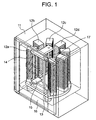
- Fig. 1 is a perspective view of a culture apparatus in accordance with a first embodiment of the present invention while partly seeing through
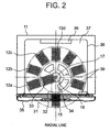
- Fig. 2 is a cross sectional view of the first embodiment as seen from an upper surface thereof
- Fig. 3 is a perspective view showing a conventional culture apparatus.
- Fig. 1 is a view of a culture apparatus while partly seeing through.
- Storage shelves 12a, 12b, 12c, ... are arranged in an inner portion of a culture apparatus 11 so as to be formed in a circular arc shape (or an annular shape).
- the storage shelves 12a, 12b, 12c, ... are placed on a table (a pedestal) 13, each of the storage shelves is provided with a plurality of slots in a vertical direction, and each of the slots has a structure which can insert or take out a culture vessel.
- the table 13 does not rotate during the culturing and the movement of the culture material (the culture vessel 18).
- the shelves 12a, 12b, 12c, ... do not move, and the culture vessel does not vibrate.
- a support portion 14 vertically supports an elevation shaft 17.
- a carrying mechanism (a carrying means) 15 turns around the elevation shaft 17, and vertically moves.
- the culture vessel 18 in which the culture material is adhered to a wall surface is inserted to or taken out from a predetermined slot position in a predetermined storage shelf on the basis of the movement of the carrying mechanism 15.
- a door 16 is provided with a carrying port for transferring the culture vessel with respect to a carrying mechanism in an external portion.
- Fig. 2 is a view as seen from an upper surface.
- the storage shelves 12a, 12b, 12c, ... holding the culture vessel 18 are arranged on the table such as to structure circular arcs 31 and 32 as a whole.
- the carrying mechanism 15 is guided (not shown) so as to freely move in a vertical direction, and is provided with a thread groove fitted to a screw thread formed in an outer periphery of the elevation shaft 17. Accordingly, a rotation force generated in the thread groove of the carrying mechanism 15 by turning the elevation shaft 17 is converted into a force in a vertical direction (a moving force) so as to move the carrying mechanism 15 in the vertical direction.
- the vertical height of the carrying mechanism 15 can be controlled by changing an output phase (CW: clockwise rotation, CCW: counterclockwise rotation) of a step to the step motor so as to rotate the step motor in the CW side or the CCW side.
- CW clockwise rotation
- CCW counterclockwise rotation
- the step number and the output phase which are required for moving the carrying mechanism 15 from the current step number to the slot at the desired height are calculated by a micro computer or the like, and thereafter, the calculated step number is output to the step motor so as to move the carrying mechanism 15 in the vertical direction.
- a guide for moving the elevation shaft 17 (including the step motor for rotating the shaft), and the carrying mechanism 15 in the vertical direction is provided on a table (not shown) turning around the same center shaft as the center shaft of the elevation shaft 17.
- the opposing storage shelf (or the desired slot) to the carrying mechanism 15 can be changed on the basis of the rotation of the table.
- the carrying mechanism 15 can be rotated to the opposing position to the desired storage shelf by changing the step number and the output phase output to the step motor for the storage shelf.
- the following three means can be considered as a means for moving the carrying mechanism 15 to the opposing position to the desired slot (the desired culture vessel).
- the gist of the present invention is not changed by using any procedure.
- aligning an initial value of the step motor and the step motor for the storage shelf is preferably carried out at least at a time of manufacturing the culture apparatus in accordance with the present invention, however, may be structured such as to be periodically carried out after installing (after using) the culture apparatus.
- the carrying mechanism 15 After the carrying mechanism 15 is moved to the opposing position to the culture vessel received in the desired slot at the desired height in the desired storage shelf, in the manner mentioned above, the carrying mechanism 15 extends the arm provided in the carrying mechanism 15 so as to insert to the lower portion of the culture vessel, and next outputs a desired number of pulses to the step motor of the elevation shaft 17 so as to slightly ascend the arm of the carrying mechanism 15 and lift up the culture vessel from the slot.
- a state 33 shown in Fig. 2 is established by retracting the arm.
- the arm in the carrying mechanism 15 can employ a general purpose structure for expanding and contracting by using a drive force of the motor (or the step motor or the like).
- the pulse number and the output phase which are output to the step motor and the step motor for the storage shelf are controlled such that the carrying mechanism 15 is moved to a state 34 shown in Fig. 2.
- the arm is extended here, and the culture vessel can be transferred with respect to the external carrying device.
- the carrying mechanism since the carrying mechanism does not pass above the other culture vessels during the carrying operation, a damage due to an accidental drop or the like is slim. Further, since a motion is reduced, it is possible to make the carrying speed high.
- the carrying mechanism operates in an inner side of the circular arc 31 and in an outer side of the circular arc 32, no extra operation space is required. Accordingly, a lot of culture materials can be received in the small-sized culture apparatus.
- the carrying port is arranged on the radial line of the circular arcs 31 and 32 so as to be in contact with the concentric circle of the circular arcs 31 and 32, it is possible to bring out the culture vessel from the carrying port only by extending the arm of the carrying mechanism 15, and no specific means is required for moving the culture vessel to the carrying port.
- a blower apparatus may be provided in the lower portion of the through hole or the circulation passage 36 in order to promote the air circulation.
- the present invention does not rotationally move the storage shelves holding the culture vessels for carrying the culture materials, it is possible to minimize the stress applied to the cells due to the vibration.
- the culture materials are arranged in the circular arc shape, and the carrying mechanism is arranged in the inner side of the circular arc arrangement of the culture materials. Accordingly, it is possible to achieve the reduction of the carrying time and reduction of the vibration. Further, since no rotating table is provided, it is easy to make the speed of the carrying mechanism high.
- the carrying mechanism is arranged in the inner side of the circular arc, it is possible to reduce the extra space required for placing and operating the carrying mechanism, so that a lot of culture materials can be received even in the small-sized culture apparatus.
- the temperature distribution within the stock room tends to be deteriorated in the case that the storage materials are received densely, however, in the present invention, since the air flow passage is structured in the inner side annularly surrounded by the storage shelves, the temperature distribution is not deteriorated.
Landscapes
- Health & Medical Sciences (AREA)
- Chemical & Material Sciences (AREA)
- Life Sciences & Earth Sciences (AREA)
- Engineering & Computer Science (AREA)
- Bioinformatics & Cheminformatics (AREA)
- Organic Chemistry (AREA)
- Wood Science & Technology (AREA)
- Zoology (AREA)
- Biochemistry (AREA)
- General Health & Medical Sciences (AREA)
- Biomedical Technology (AREA)
- Biotechnology (AREA)
- Microbiology (AREA)
- Sustainable Development (AREA)
- Genetics & Genomics (AREA)
- General Engineering & Computer Science (AREA)
- Physics & Mathematics (AREA)
- Analytical Chemistry (AREA)
- Immunology (AREA)
- Chemical Kinetics & Catalysis (AREA)
- General Physics & Mathematics (AREA)
- Pathology (AREA)
- Clinical Laboratory Science (AREA)
- Molecular Biology (AREA)
- Thermal Sciences (AREA)
- Cell Biology (AREA)
- Virology (AREA)
- Medicinal Chemistry (AREA)
- Apparatus Associated With Microorganisms And Enzymes (AREA)
- Cultivation Receptacles Or Flower-Pots, Or Pots For Seedlings (AREA)
Abstract
Description
Claims (4)
- A culture apparatus or a reserving stock room comprising:storage shelves (12a, 12b, ...) for culture vessels arranged in a circular arc shape or an annular shape; anda carrying means (15) for taking in and out said culture vessels to an inner side of said circular arc shaped arrangement or said annular shaped arrangement from said storage shelves (12a, 12b, ...).
- A culture apparatus or a reserving stock room comprising:storage shelves (12a, 12b, ...) for culture vessels arranged on a table (13) in a circular arc shape or an annular shape;an air distribution port (39) provided in said table (13) such that an air in an inner side of said circular arc shaped arrangement or said annular shaped arrangement flows from a lower side to an upper side; anda circulation passage (36) for returning the air sucked from an upper side within a stock room to said distribution port (39) via a lower side within the stock room.
- A culture apparatus or a reserving stock room as claimed in claim 1 or 2, wherein a carrying port of said culture vessel is arranged at a position on a radial line of said circular arc shaped arrangement or said annular shaped arrangement toward a center of the radial line.
- A culture apparatus or a reserving stock room as claimed in any one of claims 1 to 3, wherein a door for sealing the stock room is provided, and a carrying door smaller than the door is provided in the same side as said door.
Applications Claiming Priority (3)
| Application Number | Priority Date | Filing Date | Title |
|---|---|---|---|
| JP2002047235A JP4004310B2 (en) | 2002-02-22 | 2002-02-22 | Incubator |
| JP2002047235 | 2002-02-22 | ||
| PCT/JP2003/001745 WO2003070874A1 (en) | 2002-02-22 | 2003-02-19 | Culture device and storage container |
Publications (3)
| Publication Number | Publication Date |
|---|---|
| EP1477554A1 true EP1477554A1 (en) | 2004-11-17 |
| EP1477554A4 EP1477554A4 (en) | 2007-06-27 |
| EP1477554B1 EP1477554B1 (en) | 2009-01-07 |
Family
ID=27750682
Family Applications (1)
| Application Number | Title | Priority Date | Filing Date |
|---|---|---|---|
| EP03706958A Revoked EP1477554B1 (en) | 2002-02-22 | 2003-02-19 | Culture device and storage container |
Country Status (8)
| Country | Link |
|---|---|
| US (1) | US7785867B2 (en) |
| EP (1) | EP1477554B1 (en) |
| JP (1) | JP4004310B2 (en) |
| KR (1) | KR100961033B1 (en) |
| CN (1) | CN100577788C (en) |
| AT (1) | ATE420155T1 (en) |
| DE (1) | DE60325698D1 (en) |
| WO (1) | WO2003070874A1 (en) |
Cited By (1)
| Publication number | Priority date | Publication date | Assignee | Title |
|---|---|---|---|---|
| CH704399A1 (en) * | 2011-01-29 | 2012-07-31 | Liconic Ag | System for handling or operating laboratory objects, has storage device provided with storage for multiple laboratory objects, where transition device is arranged in storage device to transport laboratory objects |
Families Citing this family (20)
| Publication number | Priority date | Publication date | Assignee | Title |
|---|---|---|---|---|
| CA2453323A1 (en) * | 2001-07-18 | 2003-01-30 | Irm, Llc | High throughput incubation devices |
| JP5459817B2 (en) * | 2004-11-29 | 2014-04-02 | 川崎重工業株式会社 | Automatic cell culture device with articulated robot |
| CA2760982C (en) | 2009-05-15 | 2019-01-15 | Biomerieux, Inc. | System and methods for rapid identification and/or characterization of a microbial agent in a sample |
| CN102460183B (en) | 2009-05-15 | 2015-04-15 | 生物梅里埃有限公司 | Automated loading mechanism for microbiological testing equipment |
| DE102010060635B4 (en) * | 2010-11-17 | 2017-07-13 | Andreas Hettich Gmbh & Co. Kg | Storage system for an incubator |
| CN103597065B (en) * | 2011-06-14 | 2016-08-17 | 日商乐华股份有限公司 | There is the thermostat of rotating sample |
| CN103008031A (en) * | 2011-09-26 | 2013-04-03 | 上海力申科学仪器有限公司 | Method for storing and taking out samples in incubator |
| CN103008032B (en) * | 2011-09-26 | 2015-09-02 | 上海力申科学仪器有限公司 | Incubator Sample intraocular controls access method |
| CN103008034A (en) * | 2011-09-26 | 2013-04-03 | 上海力申科学仪器有限公司 | Method for placement and taking out of culture object in incubator |
| CN103008030B (en) * | 2011-09-26 | 2015-09-30 | 上海力申科学仪器有限公司 | Incubator sample store method |
| CN104169413B (en) * | 2012-02-29 | 2016-01-20 | 株式会社Jtec | There is the cell culture apparatus that nutrient solution changes function |
| CN104128219A (en) * | 2014-08-15 | 2014-11-05 | 长沙开元仪器股份有限公司 | Storing and sampling device |
| WO2020098960A1 (en) * | 2018-11-16 | 2020-05-22 | Aixinno Limited | A system for processing biology material, comprising a plurality of uniform design storage modules |
| EP3881082B1 (en) * | 2018-11-16 | 2024-03-13 | Aixinno Limited | Module for an automated biology laboratory system with an interface to transfer microplates or lab-ware |
| US12104148B1 (en) | 2019-05-17 | 2024-10-01 | Humacyte, Inc. | System, apparatuses, devices and methods for straining a cultivated tissue |
| US11959060B1 (en) | 2019-05-17 | 2024-04-16 | Humacyte, Inc. | Fluid systems, apparatuses, devices and methods of management thereof for cultivating tissue |
| US12195711B1 (en) * | 2019-05-17 | 2025-01-14 | Humacyte, Inc. | Drawer system for cultivating tissue |
| CN111398613B (en) * | 2020-03-25 | 2021-11-09 | 中国科学院遗传与发育生物学研究所 | Automatic liquid transferring system and control method thereof |
| JP6928300B1 (en) * | 2020-12-08 | 2021-09-01 | 株式会社椿本チエイン | Cold storage system |
| JP7672098B2 (en) * | 2021-03-19 | 2025-05-07 | パナソニックIpマネジメント株式会社 | Cell Culture Equipment |
Family Cites Families (16)
| Publication number | Priority date | Publication date | Assignee | Title |
|---|---|---|---|---|
| JPS5266692A (en) | 1975-12-01 | 1977-06-02 | Masahiko Izumi | Apparatus for preparing malted rice |
| US4871676A (en) * | 1987-05-28 | 1989-10-03 | Sumitomo Electric Industries, Ltd. | Cell culture incubator |
| JPH03236769A (en) | 1990-02-12 | 1991-10-22 | Mitsubishi Agricult Mach Co Ltd | Automatic apparatus for producing koji |
| JPH05266692A (en) | 1992-03-19 | 1993-10-15 | Fujitsu Ltd | Semiconductor memory device |
| JPH0787956A (en) | 1993-09-21 | 1995-04-04 | Hakuyoo:Kk | Multi-stage koji making machine |
| US5470744A (en) * | 1994-04-14 | 1995-11-28 | Astle; Thomas W. | Bioassay incubator for use with robotic arms |
| US6129428A (en) * | 1996-08-05 | 2000-10-10 | Kendro Laboratory Products Gmbh | Storage device for objects, storage station and air-conditioned cabinet |
| US6323035B1 (en) | 1997-09-24 | 2001-11-27 | Glaxo Wellcome, Inc. | Systems and methods for handling and manipulating multi-well plates |
| JPH1189559A (en) | 1997-09-25 | 1999-04-06 | Matsushita Electric Ind Co Ltd | incubator |
| JP2000093156A (en) | 1998-09-21 | 2000-04-04 | Matsushita Electric Ind Co Ltd | incubator |
| JP3330884B2 (en) | 1998-10-30 | 2002-09-30 | ハウス食品株式会社 | Food fermentation equipment |
| FR2788042A1 (en) * | 1999-01-04 | 2000-07-07 | Pierre Chaumat | Automatic modular system for storage of microtitration plates or tubes containing samples, enables thousands to be handled, conditioned, traced and retrieved for e.g. pharmaceuticals development |
| JP4141608B2 (en) | 2000-01-17 | 2008-08-27 | プレシジョン・システム・サイエンス株式会社 | Container transfer processing system |
| JP3799956B2 (en) | 2000-04-20 | 2006-07-19 | 松下電器産業株式会社 | incubator |
| JP2001352934A (en) | 2000-06-14 | 2001-12-25 | Daifuku Co Ltd | Processing equipment |
| TWI249574B (en) * | 2002-11-19 | 2006-02-21 | Sanyo Electric Co | Preserving device |
-
2002
- 2002-02-22 JP JP2002047235A patent/JP4004310B2/en not_active Expired - Fee Related
-
2003
- 2003-02-19 KR KR1020047012962A patent/KR100961033B1/en not_active Expired - Fee Related
- 2003-02-19 US US10/503,137 patent/US7785867B2/en not_active Expired - Fee Related
- 2003-02-19 DE DE60325698T patent/DE60325698D1/en not_active Expired - Lifetime
- 2003-02-19 EP EP03706958A patent/EP1477554B1/en not_active Revoked
- 2003-02-19 AT AT03706958T patent/ATE420155T1/en not_active IP Right Cessation
- 2003-02-19 CN CN03804362A patent/CN100577788C/en not_active Expired - Fee Related
- 2003-02-19 WO PCT/JP2003/001745 patent/WO2003070874A1/en not_active Ceased
Cited By (1)
| Publication number | Priority date | Publication date | Assignee | Title |
|---|---|---|---|---|
| CH704399A1 (en) * | 2011-01-29 | 2012-07-31 | Liconic Ag | System for handling or operating laboratory objects, has storage device provided with storage for multiple laboratory objects, where transition device is arranged in storage device to transport laboratory objects |
Also Published As
| Publication number | Publication date |
|---|---|
| JP4004310B2 (en) | 2007-11-07 |
| EP1477554A4 (en) | 2007-06-27 |
| CN1636049A (en) | 2005-07-06 |
| KR100961033B1 (en) | 2010-06-01 |
| US20050084955A1 (en) | 2005-04-21 |
| CN100577788C (en) | 2010-01-06 |
| WO2003070874A1 (en) | 2003-08-28 |
| EP1477554B1 (en) | 2009-01-07 |
| DE60325698D1 (en) | 2009-02-26 |
| ATE420155T1 (en) | 2009-01-15 |
| JP2003245065A (en) | 2003-09-02 |
| US7785867B2 (en) | 2010-08-31 |
| KR20040088076A (en) | 2004-10-15 |
Similar Documents
| Publication | Publication Date | Title |
|---|---|---|
| US7785867B2 (en) | Culture device and storage container | |
| US6582174B1 (en) | Substrate processing apparatus and substrate processing method | |
| JP5950876B2 (en) | Drug feeder | |
| US6475776B1 (en) | Incubator, and method for making atmosphere uniform in incubator storage box | |
| EP0613173A1 (en) | Thermal reaction chamber for semiconductor wafer processing operations | |
| JP5616728B2 (en) | Quenching equipment | |
| EP0242067A2 (en) | Wafer processing system | |
| JPH0621197A (en) | Micro circuit wafer processing equipment | |
| JP2010100312A (en) | Cap opening/closing device and dispensing system | |
| KR20080071504A (en) | Heat treatment method using vertical heat treatment device and vertical heat treatment device | |
| US11713440B2 (en) | Cell culture system and cell culture device | |
| KR20080059068A (en) | Longitudinal Heat Treatment Apparatus and Longitudinal Heat Treatment Method | |
| EP0749270A1 (en) | Automatic electronic part mounting apparatus | |
| JP2019135924A (en) | Automatic cell culture apparatus | |
| JP2018000163A (en) | Incubator apparatus for isolators | |
| JP7667718B2 (en) | Substrate Processing Equipment | |
| CN115744023A (en) | High-density storage turntable structure | |
| JPH11354603A (en) | Transport device and semiconductor manufacturing device using the same | |
| TW202344938A (en) | Substrate processing apparatus | |
| JP4236687B2 (en) | Incubator | |
| JP2009083984A (en) | Workpiece feeding device and its feeding method | |
| JP5826684B2 (en) | Substrate processing equipment | |
| US6560510B1 (en) | Simultaneous auto-loading tower | |
| CN219553598U (en) | Bearing tray for semiconductor wafer | |
| JP6928300B1 (en) | Cold storage system |
Legal Events
| Date | Code | Title | Description |
|---|---|---|---|
| PUAI | Public reference made under article 153(3) epc to a published international application that has entered the european phase |
Free format text: ORIGINAL CODE: 0009012 |
|
| 17P | Request for examination filed |
Effective date: 20040907 |
|
| AK | Designated contracting states |
Kind code of ref document: A1 Designated state(s): AT BE BG CH CY CZ DE DK EE ES FI FR GB GR HU IE IT LI LU MC NL PT SE SI SK TR |
|
| A4 | Supplementary search report drawn up and despatched |
Effective date: 20070529 |
|
| 17Q | First examination report despatched |
Effective date: 20070817 |
|
| GRAP | Despatch of communication of intention to grant a patent |
Free format text: ORIGINAL CODE: EPIDOSNIGR1 |
|
| GRAS | Grant fee paid |
Free format text: ORIGINAL CODE: EPIDOSNIGR3 |
|
| GRAA | (expected) grant |
Free format text: ORIGINAL CODE: 0009210 |
|
| AK | Designated contracting states |
Kind code of ref document: B1 Designated state(s): AT BE BG CH CY CZ DE DK EE ES FI FR GB GR HU IE IT LI LU MC NL PT SE SI SK TR |
|
| REG | Reference to a national code |
Ref country code: GB Ref legal event code: FG4D |
|
| REG | Reference to a national code |
Ref country code: CH Ref legal event code: EP |
|
| REG | Reference to a national code |
Ref country code: IE Ref legal event code: FG4D |
|
| REF | Corresponds to: |
Ref document number: 60325698 Country of ref document: DE Date of ref document: 20090226 Kind code of ref document: P |
|
| PG25 | Lapsed in a contracting state [announced via postgrant information from national office to epo] |
Ref country code: SI Free format text: LAPSE BECAUSE OF FAILURE TO SUBMIT A TRANSLATION OF THE DESCRIPTION OR TO PAY THE FEE WITHIN THE PRESCRIBED TIME-LIMIT Effective date: 20090107 |
|
| PG25 | Lapsed in a contracting state [announced via postgrant information from national office to epo] |
Ref country code: ES Free format text: LAPSE BECAUSE OF FAILURE TO SUBMIT A TRANSLATION OF THE DESCRIPTION OR TO PAY THE FEE WITHIN THE PRESCRIBED TIME-LIMIT Effective date: 20090418 Ref country code: FI Free format text: LAPSE BECAUSE OF FAILURE TO SUBMIT A TRANSLATION OF THE DESCRIPTION OR TO PAY THE FEE WITHIN THE PRESCRIBED TIME-LIMIT Effective date: 20090107 |
|
| PG25 | Lapsed in a contracting state [announced via postgrant information from national office to epo] |
Ref country code: SE Free format text: LAPSE BECAUSE OF FAILURE TO SUBMIT A TRANSLATION OF THE DESCRIPTION OR TO PAY THE FEE WITHIN THE PRESCRIBED TIME-LIMIT Effective date: 20090407 Ref country code: AT Free format text: LAPSE BECAUSE OF FAILURE TO SUBMIT A TRANSLATION OF THE DESCRIPTION OR TO PAY THE FEE WITHIN THE PRESCRIBED TIME-LIMIT Effective date: 20090107 Ref country code: PT Free format text: LAPSE BECAUSE OF FAILURE TO SUBMIT A TRANSLATION OF THE DESCRIPTION OR TO PAY THE FEE WITHIN THE PRESCRIBED TIME-LIMIT Effective date: 20090608 |
|
| PG25 | Lapsed in a contracting state [announced via postgrant information from national office to epo] |
Ref country code: BE Free format text: LAPSE BECAUSE OF FAILURE TO SUBMIT A TRANSLATION OF THE DESCRIPTION OR TO PAY THE FEE WITHIN THE PRESCRIBED TIME-LIMIT Effective date: 20090107 Ref country code: MC Free format text: LAPSE BECAUSE OF NON-PAYMENT OF DUE FEES Effective date: 20090228 |
|
| PLBI | Opposition filed |
Free format text: ORIGINAL CODE: 0009260 |
|
| PG25 | Lapsed in a contracting state [announced via postgrant information from national office to epo] |
Ref country code: EE Free format text: LAPSE BECAUSE OF FAILURE TO SUBMIT A TRANSLATION OF THE DESCRIPTION OR TO PAY THE FEE WITHIN THE PRESCRIBED TIME-LIMIT Effective date: 20090107 Ref country code: DK Free format text: LAPSE BECAUSE OF FAILURE TO SUBMIT A TRANSLATION OF THE DESCRIPTION OR TO PAY THE FEE WITHIN THE PRESCRIBED TIME-LIMIT Effective date: 20090107 Ref country code: CZ Free format text: LAPSE BECAUSE OF FAILURE TO SUBMIT A TRANSLATION OF THE DESCRIPTION OR TO PAY THE FEE WITHIN THE PRESCRIBED TIME-LIMIT Effective date: 20090107 |
|
| PLAX | Notice of opposition and request to file observation + time limit sent |
Free format text: ORIGINAL CODE: EPIDOSNOBS2 |
|
| 26 | Opposition filed |
Opponent name: THERMO ELECTRON LED GMBH Effective date: 20091007 |
|
| REG | Reference to a national code |
Ref country code: IE Ref legal event code: MM4A |
|
| PG25 | Lapsed in a contracting state [announced via postgrant information from national office to epo] |
Ref country code: SK Free format text: LAPSE BECAUSE OF FAILURE TO SUBMIT A TRANSLATION OF THE DESCRIPTION OR TO PAY THE FEE WITHIN THE PRESCRIBED TIME-LIMIT Effective date: 20090107 |
|
| PG25 | Lapsed in a contracting state [announced via postgrant information from national office to epo] |
Ref country code: BG Free format text: LAPSE BECAUSE OF FAILURE TO SUBMIT A TRANSLATION OF THE DESCRIPTION OR TO PAY THE FEE WITHIN THE PRESCRIBED TIME-LIMIT Effective date: 20090407 Ref country code: IE Free format text: LAPSE BECAUSE OF NON-PAYMENT OF DUE FEES Effective date: 20090219 |
|
| NLR1 | Nl: opposition has been filed with the epo |
Opponent name: THERMO ELECTRON LED GMBH |
|
| PLAF | Information modified related to communication of a notice of opposition and request to file observations + time limit |
Free format text: ORIGINAL CODE: EPIDOSCOBS2 |
|
| PLBB | Reply of patent proprietor to notice(s) of opposition received |
Free format text: ORIGINAL CODE: EPIDOSNOBS3 |
|
| PG25 | Lapsed in a contracting state [announced via postgrant information from national office to epo] |
Ref country code: GR Free format text: LAPSE BECAUSE OF FAILURE TO SUBMIT A TRANSLATION OF THE DESCRIPTION OR TO PAY THE FEE WITHIN THE PRESCRIBED TIME-LIMIT Effective date: 20090408 |
|
| PG25 | Lapsed in a contracting state [announced via postgrant information from national office to epo] |
Ref country code: IT Free format text: LAPSE BECAUSE OF FAILURE TO SUBMIT A TRANSLATION OF THE DESCRIPTION OR TO PAY THE FEE WITHIN THE PRESCRIBED TIME-LIMIT Effective date: 20090107 |
|
| PG25 | Lapsed in a contracting state [announced via postgrant information from national office to epo] |
Ref country code: LU Free format text: LAPSE BECAUSE OF NON-PAYMENT OF DUE FEES Effective date: 20090219 |
|
| PG25 | Lapsed in a contracting state [announced via postgrant information from national office to epo] |
Ref country code: HU Free format text: LAPSE BECAUSE OF FAILURE TO SUBMIT A TRANSLATION OF THE DESCRIPTION OR TO PAY THE FEE WITHIN THE PRESCRIBED TIME-LIMIT Effective date: 20090708 |
|
| PG25 | Lapsed in a contracting state [announced via postgrant information from national office to epo] |
Ref country code: TR Free format text: LAPSE BECAUSE OF FAILURE TO SUBMIT A TRANSLATION OF THE DESCRIPTION OR TO PAY THE FEE WITHIN THE PRESCRIBED TIME-LIMIT Effective date: 20090107 |
|
| PG25 | Lapsed in a contracting state [announced via postgrant information from national office to epo] |
Ref country code: CY Free format text: LAPSE BECAUSE OF FAILURE TO SUBMIT A TRANSLATION OF THE DESCRIPTION OR TO PAY THE FEE WITHIN THE PRESCRIBED TIME-LIMIT Effective date: 20090107 |
|
| PGFP | Annual fee paid to national office [announced via postgrant information from national office to epo] |
Ref country code: FR Payment date: 20120221 Year of fee payment: 10 Ref country code: CH Payment date: 20120214 Year of fee payment: 10 |
|
| PGFP | Annual fee paid to national office [announced via postgrant information from national office to epo] |
Ref country code: DE Payment date: 20120215 Year of fee payment: 10 |
|
| PGFP | Annual fee paid to national office [announced via postgrant information from national office to epo] |
Ref country code: GB Payment date: 20120215 Year of fee payment: 10 |
|
| REG | Reference to a national code |
Ref country code: NL Ref legal event code: SD Effective date: 20120709 |
|
| REG | Reference to a national code |
Ref country code: DE Ref legal event code: R082 Ref document number: 60325698 Country of ref document: DE Representative=s name: MARKUS REINHARDT, DE |
|
| REG | Reference to a national code |
Ref country code: DE Ref legal event code: R082 Ref document number: 60325698 Country of ref document: DE Representative=s name: MARKUS REINHARDT, DE |
|
| PGFP | Annual fee paid to national office [announced via postgrant information from national office to epo] |
Ref country code: NL Payment date: 20120221 Year of fee payment: 10 |
|
| REG | Reference to a national code |
Ref country code: FR Ref legal event code: TP Owner name: PANASONIC HEALTHCARE CO LTD, JP Effective date: 20120730 |
|
| REG | Reference to a national code |
Ref country code: DE Ref legal event code: R081 Ref document number: 60325698 Country of ref document: DE Owner name: PANASONIC HEALTHCARE CO., LTD., TOON-SHI, JP Free format text: FORMER OWNER: SANYO ELECTRIC CO., LTD., SANYO ELECTRIC BIOMEDICAL CO.,, , JP Effective date: 20120716 Ref country code: DE Ref legal event code: R082 Ref document number: 60325698 Country of ref document: DE Representative=s name: REINHARDT, MARKUS, DIPL.-ING.UNIV., DE Effective date: 20120723 Ref country code: DE Ref legal event code: R082 Ref document number: 60325698 Country of ref document: DE Representative=s name: REINHARDT, MARKUS, DIPL.-ING.UNIV., DE Effective date: 20120716 Ref country code: DE Ref legal event code: R081 Ref document number: 60325698 Country of ref document: DE Owner name: PANASONIC HEALTHCARE CO., LTD., TOON-SHI, JP Free format text: FORMER OWNER: SANYO ELECTRIC CO., LTD., MORIGUCHI-SHI, OSAKA, JP Effective date: 20120723 Ref country code: DE Ref legal event code: R081 Ref document number: 60325698 Country of ref document: DE Owner name: PANASONIC HEALTHCARE CO., LTD., JP Free format text: FORMER OWNER: SANYO ELECTRIC CO., LTD., SANYO ELECTRIC BIOMEDICAL CO.,, , JP Effective date: 20120716 Ref country code: DE Ref legal event code: R081 Ref document number: 60325698 Country of ref document: DE Owner name: PANASONIC HEALTHCARE CO., LTD., JP Free format text: FORMER OWNER: SANYO ELECTRIC CO., LTD., MORIGUCHI-SHI, JP Effective date: 20120723 Ref country code: DE Ref legal event code: R081 Ref document number: 60325698 Country of ref document: DE Owner name: PANASONIC HEALTHCARE CO., LTD., TOON-SHI, JP Free format text: FORMER OWNERS: SANYO ELECTRIC CO., LTD., MORIGUCHI-SHI, OSAKA, JP; SANYO ELECTRIC BIOMEDICAL CO., LTD., MORIGUCHI, OSAKA, JP Effective date: 20120716 |
|
| REG | Reference to a national code |
Ref country code: GB Ref legal event code: 732E Free format text: REGISTERED BETWEEN 20120816 AND 20120822 |
|
| REG | Reference to a national code |
Ref country code: DE Ref legal event code: R064 Ref document number: 60325698 Country of ref document: DE Ref country code: DE Ref legal event code: R103 Ref document number: 60325698 Country of ref document: DE |
|
| RDAF | Communication despatched that patent is revoked |
Free format text: ORIGINAL CODE: EPIDOSNREV1 |
|
| REG | Reference to a national code |
Ref country code: NL Ref legal event code: SD Effective date: 20131101 |
|
| RDAG | Patent revoked |
Free format text: ORIGINAL CODE: 0009271 |
|
| STAA | Information on the status of an ep patent application or granted ep patent |
Free format text: STATUS: PATENT REVOKED |
|
| REG | Reference to a national code |
Ref country code: CH Ref legal event code: PL |
|
| 27W | Patent revoked |
Effective date: 20120924 |
|
| GBPR | Gb: patent revoked under art. 102 of the ep convention designating the uk as contracting state |
Effective date: 20120924 |
|
| PG25 | Lapsed in a contracting state [announced via postgrant information from national office to epo] |
Ref country code: CH Free format text: LAPSE BECAUSE OF THE APPLICANT RENOUNCES Effective date: 20090107 Ref country code: LI Free format text: LAPSE BECAUSE OF THE APPLICANT RENOUNCES Effective date: 20090107 |
|
| REG | Reference to a national code |
Ref country code: DE Ref legal event code: R107 Ref document number: 60325698 Country of ref document: DE Effective date: 20130926 |