FIELD OF THE INVENTION
The present invention relates to a method of treating
photographic waste liquid, specifically to a practical
and economical treatment method of photographic
processing waste liquid hitherto considered to be
difficult to treat to an extent meeting the effluent
standards of Sewerage Law. In particular, the invention
relates to a photographic waste liquid treatment method
capable of working in photofinishing laboratories.
BACKGROUND OF THE INVENTION
Liquid wastes discharged in various photographic
processing steps are collected generally in a mixed state,
and treated as photographic waste liquid. Diversity of
the waste liquid composition makes it difficult to find
effective methods for waste liquid treatment. So the
photographic waste liquid is one of the most
difficult-to-treat industrial effluents. Although a
number of treatment methods for photographic waste liquid
have so far been disclosed, they still have many problems
with both removal rate and treatment cost.
As a realistic countermeasure, photographic waste
liquid is consigned to persons involved in recovery and
disposal of effluent, and incinerated by them. For
performing incineration without emitting ecologically
deleterious substances into the air andwater environments,
it is necessary to raise the incineration temperature.
However, incineration disposal is difficult to perform
by continuous operation of a middle- or small-scale
incinerator at high temperatures. So the incineration
has to be carried out using a large-scale incinerator
and cannot help involving a high disposal cost. In
addition, for the purpose of avoiding pipe clogging and
wearing away of the incinerator by high melting inorganic
salts, such as iron oxides, produced by burning, it is
required to provide a chemical iron-removal step.
Therefore, the disposal by incinerator has a problem with
further complexity of disposal process and operation.
Under these circumstances, the incineration
disposal, though a realistic countermeasure, is not a
satisfactory countermeasure at present. So studies of
more excellent treatment techniques for photographic
waste liquid have been made continually.
The methods hitherto disclosed with respect to the
treatments for photographic waste liquid are mainly
biological, chemical and physical treatments.
As examples of the biological treatment are
disclosed many methods of treating photographic waste
liquid by use of activated sludge, inclusive of the method
for reducing COD of waste liquid from medical X-ray film
processing as disclosed in JP-A-59-42094. In these
treatment methods, waste liquid diluted generally by a
factor of 10 to 50 is treated with activated sludge for
a period (an average residence time) of 15 to 50 days.
As a result, the waste liquid is said to receive a 50-80 %
reduction of COD and a 50-80% reduction of BOD by
decomposition and removal.
Examples of chemical treatment (oxidation method)
include an ozone oxidation method, a hydrogen peroxide
oxidation method, oxidation methods using other chemical
oxidants, and an electrolytic oxidation method. The
ozone oxidation method is disclosed, e.g., in JP-A-7-47347.
Although it is an effective method for decomposition and
removal of inorganic ingredients as a COD component and
decomposition of benzene rings contained in aromatic
developing agents, ozone oxidation has a minimal effect
on the removal of organic ingredients as a BOD component.
As to the method of using hydrogen peroxide, the method
of using hydrogen peroxide in combination with a catalyst
is disclosed in JP-A-9-234475. In addition, the hydrogen
peroxide-ferric salt method (Fenton method), though
effective for both inorganic and organic ingredients,
is attended with a treatment-cost problem. Further,
there are known the method of using persulfate as an oxidant,
the method of adding an oxidant to a strong acidic solution
and thereby depositing sulfur compounds in a stabilized
condition, the method of oxidizing with chlorine and
hypochlorite, and the treatment method of heating in the
presence of persulfate.
Of those methods, the electrolytic oxidation method
has advantages that it ensures easy and safe operations
and enables reduction of apparatus size in contrast to
oxidation treatment with a strong chemical oxidizing agent,
and simple in comparison with biological treatment and
physical treatment. The electrolytic oxidation methods
are disclosed, e.g., in JP-A-63-116796, JP-A-8-296081
and JP-A-7-323290. In the process of electrolyzing
photographic processing waste liquid, however, oxidized
species produced upon electrolysis decompose organic
substances with efficiency when the organic component
concentration is high, but it occurs in many cases that
at the time when the organic substances are decomposed
into lower fatty acids including_acetic acid, formic acid
and oxalic acid the efficiency of further decomposition
by electrolysis is lowered to result in waste of electric
power.
In general, it is said that the COD component removal
rate (reduction rate) attained by chemical treatment is
of the order of 50%.
Examples of physical treatment include a
high-pressure heating method, an atomization burning
method and an evaporative drying method. Since a large
amount of halide ions are contained in photographic waste
liquid, stress corrosion of a reactor becomes a problem.
In addition, the heat exchanger used for heat recovery
has a problemwith disposal of scales, residues and exhaust
gases.
Further examples of hitherto proposed physical
treatment include an adsorptive removal method using an
inorganic or organic high polymer adsorbent, a reverse
osmosis method and a dialysis method.
When any of the foregoing methods is used anone,
however, it cannot have satisfactory treatment effect
upon photographic waste liquid in which a wide variety
of chemical substances causing environmental pollution
are present. For instance, an problem with the chemical
oxidation method (1) is a great cost increase caused by
consumption of a large amount of chemical reagents, an
problem with the electrolytic oxidation method (2) is
a drop in COD reduction rate resulting from fouling of
electrodes, an problem with the absorptive removal method
(3) is an adsorbent usage increased with decreasing
adsorption power, an problem with the evaporation method
(4) is an release of an offensive order and toxic substances,
an problem with the microbial treatment method (5) is
a decrease of microorganisms' ability to treat COD
components in the presence of deleterious substances,
and an problem with the reverse-osmosis or dialysis method
(6) is a short life of column or film.
As improvement measures, combinations of the
foregoing methods, especially a combination of oxidation
treatment and microbial treatment, have been proposed.
For instance, JP-A-3-262594 discloses that both of COD
and BOD of photographic waste liquid can be reduced by
the combination of hydrogen peroxide oxidation treatment
(Fenton method) and microbial treatment, JP-A-4-235786,
JP-A-6-320184 and JP-A-4-244299 disclose the
electrolytic treatment-microbial treatment combinations
enabling reductions in COD and BOD of photographic waste
liquid, and JP-A-5-96298 discloses that the COD and BOD
of photographic waste liquid can be reduced by using
photochemical oxidation with ozone gas in combination
with microbial treatment. However, these combination
methods each involve any of such problems that the size
of apparatus becomes large and thereby a large space for
installation of the apparatus is required, operations
become complicated, special microorganisms are required
for treatment, and dilution with a large quantity of water
is required. Therefore, any of them cannot afford a
satisfactory solution.
Of those treatments, the electrolysis method used
for treatment of waste liquid features easy and safe
operations and reduction in apparatus size, compared with
the oxidation treatment using strong chemical oxidants.
However, in the process of electrolyzing photographic
processing waste liquid, oxidized species produced upon
electrolysis decompose organic substances with
efficiency when the organic component concentration is
high, but it occurs in many cases that at the time when
the organic substances are decomposed into lower fatty
acids including acetic acid, formic acid and oxalic acid
the efficiency of further decomposition by electrolysis
is lowered to result in waste of electric power. In the
electrolysis of those organic acids, the potential window
is still narrow even when platinum and lead electrodes
are used, so there is no improvement in electrolysis
efficiency. In addition, the use of platinum and lead
electrodes causes a trouble of eluting heavy metal ions.
JP-A-7-299467 discloses the electrolytic oxidation
method using a positive electrode having a
diamond-evaporated surface. Therein, it is shown that
such an electrode enables an increase in impressed voltage
to result in enhancement of the effect of decomposing
organic substances. However, any of the methods
mentioned above still falls short of meeting the effluent
standards of Sewerage Law.
On the other hand, in view of the composition of
photographic waste liquid, biological treatments with
aerobic microorganisms have a common inevitable drawback
of requiring a large volume of dilution water for their
application to photographic waste liquid and consequent
upsizing of apparatus. Therefore, these treatments are
practicable in large-scale waste-treatment sites where
photographic waste liquid is accumulated and treated
intensively, preferably together with other liquid wastes,
but it is disadvantageous to carry out them in
photofinishing laboratories where photographic waste
liquid generates because the volume of waste liquid to
be treated is increased by water dilution to result in
increases of equipment cost, installation space and
operation cost. Although the foregoing complex
treatment techniques involving biological treatment can
raise reduction rates of COD and BOD, they have problems
peculiarly their own as mentioned above and disadvantages
associated with water dilution, so it is impractical to
apply them in photofinishing laboratories.
In contrast, anaerobe treatments can often be
applied effectively to liquid wastes having high salt
concentrations and high COD. However, anaerobic
treatment cannot be applied to photographic waste liquid
because the waste liquid has a high sulfur compound content
and produceshydrogensulfidebyreduction under anaerobic
conditions, thereby making it impossible for
microorganisms to survive.
In photofinishing laboratories, as mentioned above,
it is difficult to perform not only biological treatment,
irrespective of whether it is aerobic or anaerobic, but
also complex treatment methods wherein biological
treatment is combined with other treatments. So
photographic waste liquid is transported from
photofinishing laboratories to an outside centralized
treatment site to which the treatment thereof is
commissioned. Under these circumstances, a waste
treatment method which makes it possible for both BOD
and COD of photographic waste liquid to be reduced to
no higher than drainage standard values and has
practicability in photofinishing laboratories also is
desired strongly.
As mentioned above, any of the hitherto disclosed
waste liquid treatment methods, irrespective of whether
they are used in isolation or in combination, falls short
of perfectly solving the problems of the hour, and they
are difficult to carry out in photofinishing laboratories
in particular. Therefore, it is strongly desired to find
a method of reducing BOD and COD of photographic waste
liquid to a level lower than the effluent standards,
especially a photographic waste liquid treatment method
which can be carried out in photofinishing laboratories
also.
SUMMARY OF THE INVENTION
An object of the present invention is to provide
a photographic waste liquid treatment method which can
ensure effective reductions of BOD and COD even when the
volume of dilution water required at the time of biological
treatment of the photographic waste liquid is reduced.
And a further object thereof is to enable treatment of
photographic processing waste liquid in a photofinishing
laboratory, or on-site treatment, by application of the
aforesaid photographic waste liquid treatment method.
Another object of the present invention is to provide
a photographic waste liquid treatment method enabling
effective reduction in COD of photographic waste liquid.
More specifically, the invention aims to present an
electrolytic oxidation treatment method which enables
effective reduction in COD of photographic waste liquid
and causes no abnormal drop in COD reduction efficiency.
And another object of the invention is to provide a
treatment apparatus for practicing such an electrolytic
oxidation treatment method.
Another object of the present invention is to provide
a photographic waste liquid treatment method which enables
effective reductions in BOD and COD of photographic waste
liquid, and a further obj ect thereof is to provide a method
applicable to photographic waste liquid treatment in
photofinishing laboratories, or an on-site treatment
method for photographic waste liquid, which can ensure
effective reductions in both BOD and COD.
A further object of the invention is to present a
method of effectively removing silver from
silver-containing photographic waste liquid and
recovering the silver with efficiency.
Under our intensive studies pursued while focusing
attention particularly on a connection between
microorganisms' activities and the composition and salt
concentration of photographic waste liquid for the purpose
of finding a solution to the foregoing problems, it has
come to discover a special composition condition for
maintaining activities of microorganisms even when the
photographic waste liquid to be treated has a high salt
concentration, thereby achieving the invention. That is,
the following is a first embodiment of the invention.
1. A method of treating photographic waste liquid,
comprising: adjusting photographic waste liquid so as
to have a COD/ammoniacal nitrogen ratio of 3 or below;
performing a physicochemical oxidation treatment to the
adjusted photographic waste liquid; and then performing
a biological treatment to the treated photographic waste
liquid.
2. The method of treating photographic waste liquid
as described in the item 1, wherein the photographic waste
liquid having been subjected to the physicochemical
oxidation treatment is subjected to the biological
treatment directly or in a state of water dilution having
a dilution factor of 1 to 4, wherein the dilution factor
is defined as a ratio of (volume of waste liquid after
dilution with water) to (volume of undiluted waste
liquid).
3. The method of treating photographic waste liquid
as described in the item 1 or 2, wherein the photographic
waste liquid is further adjusted so as to have a sulfur
content of 5 g/L to 20 g/L.
4. The method of treating photographic waste liquid
as described in any one of the items 1 to 3, wherein the
physicochemical oxidation treatment of the photographic
waste liquid is an electrolytic oxidation treatment.
5. The method of treating photographic waste liquid
as described in any one of the items 1 to 4, wherein the
biological treatment is an activated-sludge treatment.
6. The method of treating photographic waste liquid
as described in any one of the items 1 to 5, wherein the
biological treatment is a treatment with microorganisms
immobilized in a carrier.
7. The method of treating photographic waste liquid
as described in any one of the items 1 to 6, wherein the
photographic waste liquid is color photographic waste
liquid.
8. Themethodof treatingphotographic waste liquid
as described in any one of the items 1 to 7, wherein the
photographic waste liquid contains a hardly biodegradable
compound.
Also, in the process of tracking down the cause
of a COD reduction rate drop greater than that commensurate
with the decrease of the liquid waste component
contributory to COD for the purpose of finding a solution
to the aforementioned problem, we just happened to carry
out electrolysis of photographic waste liquid while
removing precipitates produced from the waste liquid
during the electrolytic oxidation and discovered that
neither inner wall of the electrolytic cell nor the
electrode surfaces were fouled, and what is more, the
abnormal drop in COD reduction rate was resolved to our
surprise and the electrolysis was proceeding at a rate
commensurate with the residual content of the component
contributory to COD.
The invention has been made on the basis of this
discovery, and the following is a second embodiment of
the invention.
9. A method of electrolytic oxidation treatment
for photographic waste liquid, wherein the electrolytic
oxidation treatment is carried out while removing
precipitates produced during the electrolytic oxidation
treatment.
10. An apparatus for an electrolytic oxidation
treatment to photographic waste liquid, comprising a means
for removing precipitates produced from the photographic
waste liquid by the electrolytic oxidation treatment.
11. The apparatus for an electrolytic oxidation
treatment to photographic waste liquid as described in
the item 10, wherein the means for removing the
precipitates is a filtering device.
12. The apparatus for an electrolytic oxidation
treatment to photographic waste liquid as described in
the item 10, wherein the means for removing the
precipitates is a sedimentation tank.
13. The apparatus for an electrolytic oxidation
treatment to photographic waste liquid as described in
any one of the items 10 to 12, which comprises a conductive
diamond electrode as a positive electrode.
14. Amethod of recovering silver from photographic
waste liquid, comprising: preforming an electrolytic
oxidation treatment to photographic processing waste
liquid; separating precipitates produced during the
electrolytic oxidation treatment from the waste liquid;
and recovering silver contained in the precipitates.
Under our intensive research into potential
materials for electrodes used in electrolytic methods
relatively easier and safer in operations than chemical
methods and the potential of the combination of
electrolysis method and biological treatment, which has
been made with the intention of finding a solution to
the foregoing problems, it has come to discover that the
photographic waste liquid electrolyzed to a certain extent
by means of a diamond electrode became free of
hard-to-biodegrade substances, such as EDTA, through
electrolytic decomposition and the TOC (Total Organic
Carbon) content therein was rapidly reduced by biological
treatment with activated sludge, thereby achieving the
invention. That is, the following is a third embodiment
of the invention.
15. Amethod of treating photographic waste liquid,
comprising: performing an electrolytic oxidation
treatment to photographic waste liquid, in which a
conductive diamond electrode is used as a positive
electrode; and then performing a biological treatment
to the treated photographic waste liquid.
16. The method of treating photographic waste
liquid as described in the item 15, wherein the biological
treatment is preformed after a 70% or greater reduction
in COD of photographic processing waste liquid is achieved
by the electrolytic oxidation treatment.
17. The method of treating photographic waste
liquid as described in the item 15 or 16, wherein in the
electrolytic oxidation treatment, a conductive diamond
electrode is used as both positive electrode and negative
electrode.
18. The method of treating photographic waste
liquid as described in the item 17, wherein a polarity
inversion in the positive electrode and the negative
electrode is performed in the electrolytic oxidation
treatment.
19. The method of treating photographic waste
liquid as described in any one of the items 15 to 18,
wherein the biological treatment is activated-sludge
treatment.
20. The method of treating photographic waste
liquid as described in any one of the items 15 to 19,
wherein the biological treatment is a treatment with high
salt concentration resistance bacteria.
21. The method of treating photographic waste
liquid as described in any one of the items 15 to 20,
wherein the biological treatment is a treatment with
microorganisms immobilized by a carrier.
Brief Description of the Drawings
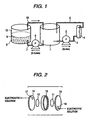
Fig. 1 is a schematic diagram showing an embodiment
of the present sedimentation tank-equipped electrolytic
oxidation apparatus for photographic waste liquid.
Fig. 2 is an illustration to show the structure of
an electrolytic cell in an electrolytic oxidation
apparatus used in the invention.
Fig. 3 is a schematic diagram showing an embodiment
of the filter tank-equipped electrolytic oxidation
apparatus for photographic waste liquid, which is used
in Example.
Fig. 4 is a schematic diagram showing another
embodiment of the sedimentation tank-equipped
electrolytic oxidation apparatus for photographic waste
liquid, which is also used in Example.
Description of Reference Numerals and Signs
- 1.
- Waste liquid tank
- 2.
- Feed pump
- 3.
- Feed pipe
- 4.
- Electrolytic cell
- 5.
- Return pipe
- 6.
- Feed pump
- 7.
- Feed pipe
- 8.
- Sedimentation tank
- 9.
- Precipitate
- 10.
- Supernatant layer
- 11.
- Positive electrode
- 12.
- Negative electrode
- 13,14.
- Disk-form outer flames
- 15.
- Annular spacer
- 16,17.
- Openings for passage of liquor
- 18.
- Return pipe
- 21.
- Waste liquid tank
- 24.
- Electrolytic cell
- 25,28.
- Return pipes
- 26.
- Filtering device
- 27.
- Outlet
- 31.
- Waste liquid tank
- 34.
- Electrolytic cell
- 37.
- Feed pipe
- 39,40.
- Precipitates
- 41,42.
- Supernatant layers
- 43,44.
- Sedimentation tanks
- 46.
- Return pipe
The important point in the present treatment method
of photographic waste liquid in the first embodiment of
the present invention is to begin by adjusting
photographic waste liquid to undergo treatment so as to
have a COD/ammoniacal nitrogen ratio (hereinafter
abbreviated as "a COD/N ratio") of 3 or below in advance
of biological treatment of the photographic waste liquid,
and then to give physicochemical oxidation treatment to
the photographic waste liquid. And our finding consists
in that the waste liquid having received physicochemical
oxidation treatment after the COD/N ratio adjustment to
a value within the foregoing range has little ill effect
on activities of microorganisms (biodegradable
microorganisms) in spite of its high salt concentration.
Therefore, it becomes possible in the invention to carry
out biological treatment at a dilution rate of no greater
than 4 or directly without dilution, although general
cases require a dilution rate of at least 10, frequently
of the order of 50, for attaining salt concentrations
enabling biological treatment. Thus, the volume of
apparatus for biological treatment can be reduced
epochally, and waste liquid treatment in small- to
medium-sized photofinishing laboratories also (on-site
treatment of waste liquid) becomes practicable.
Although the mechanism for producing such an effect
remains uncertain, one possible mechanism is thought to
be as follows: When ammoniacal nitrogen is present in
a large amount, organic acids produced by physicochemical
oxidation are converted into ammonium salts having less
influences on living things than alkali metal salts; as
a result, dilution for the subsequent biological treatment
can get off by using only a limited volume of water. In
other words, this unexpected effect is supposed to be
produced by carrying out physicochemical oxidation in
the specified range of COD/N ratios. However, the present
method should not be construed as excluding usual cases
wherein water dilution for biological treatment is
performed at high level of dilution factors.
Moreover, the present photographic waste liquid
treatment method in the first embodiment can achieve its
best effect when applied to waste liquid having a sulfur
content adjusted to the range of 5 g/L to 20 g/L. Although
it is the actual situation that photographic waste liquid
contains an abundance of both sulfur and sulfur-containing
compounds derived from sulfites and thiosulfates present
in photographic processing solutions and the effect of
biological treatment is marred by those sulfur and
sulfur-containing compounds when the biological
treatment is carried out in combination with chemical
oxidation treatment, the invention sees no sign of such
a detrimental effect, but efficient proceeding of
biodegradation. Although the mechanism thereof is also
unclear, it is probable that ammoniacal nitrogen present
in a high concentration forms salts by reacting with
oxidative products, inclusive of sulfuric acid ion, from
physicochemical oxidation of sul fur compounds and thereby
the oxidative products are rendered harmless to
microorganisms.
The invention is described below in further detail.
Hereinafter, microorganisms involved in
biodegradation are sometimes referred to as
"microorganisms", but these two terms may be construed
as having the same meaning. Additionally, "photographic
processing waste liquid" is synonymous with "photographic
waste liquid" as an abbreviated expression for the former.
In the second embodiment of the present invention,
as described above, a feature of the present method of
electrolytic oxidation treatment for photographic waste
liquid consists in the adoption of a simple measure of
performing electrolytic oxidation treatment of
photographic wasteliquid whileremovingtheprecipitates
produced during the treatment. By taking this measure
can be achieved not only the effect of preventing the
electrolytic cell and the electrodes from becoming fouled,
which is expected as a matter of course, but also the
unexpected effect of improving the decomposition rate
of photographic waste liquid (COD or TOC removal rate)
to the level meeting the effluent standards of Sewerage
Law.
As a result of enabling the photographic waste liquid
treatment by electrolytic oxidation alone, a small space
will suffice for the treatment and the on-site waste liquid
treatment can also be performed in photofinishing
laboratories.
Incidentally, the COD and BOD values are adopted
for oxygen-consuming organic substances in effluent from
a law-regulation viewpoint. With respect to
photographic waste liquid, on the other hand, COD and
TOC have substantially the same meaning from the
standpoint of effluent standards. Since the TOC
measurement is easy because of its simplicity, the
specification hereinafter has some descriptions using
TOC in place of COD. Even when either value is adopted,
there is no difference in technological substance to the
present objects.
In the third embodiment, as is clear from the above
descriptions, the feature of the present photographic
waste liquid treatment method is that a diamond electrode
is used in electrolytic oxidation treatment for
photographic waste liquid. The use of a conductive
diamond electrode enables effective decomposition of
hard-to-biodegrade ingredients in photographic waste
liquid, such as EDTA and PEG, without attended by
deterioration in electrolysis efficiency due to fouling
of the electrode; as a result, biodegradation in
biological treatment after the electrolysis proceeds with
ease to bring about considerable reductions in BOD and
COD, and by extension to make it possible to meet the
effluent standard. This excellent effect is thought to
come about for a reason that the potential window of
oxidation at the positive electrode is wide due to a high
hydrogen overvoltage of the diamond electrode and hydroxyl
radicals as an effective oxidant species are produced
with efficiency. Moreover, unlike heavy metal
electrodes, the diamond electrode placed in waste liquid
under treatment causes neither contamination with metals
eluted from the positive electrode nor deactivation of
activated sludge by silver ions in the photographic waste
liquid because of almost complete precipitation of silver
ions as silver sulfide. On the other hand, known zinc
oxide, tin oxide and platinum electrodes cannot achieve
such a high electrolysis efficiency as the diamond
electrode can deliver, and they entail contamination of
the treated waste liquid by elution from the positive
electrode.
A defect of traditional biological treatment with
activated sludge, namely insufficient biodegradation the
photographic waste liquid undergoes through such a
treatment, is obviated by carrying out electrolytic
oxidation utilizing a diamond electrode as pretreatment.
As a result, an excellent method of treating photographic
waste liquid by utilizing advantages of biological
treatment, namely treatment under ordinary temperature
and pressure, with no chemical reagent and at a low energy
cost, can be realized. A further advantage of this method
is in that the biological treatment of electrolytically
oxidized waste liquid can be effected in a diluted state
by a relatively low dilution factor (of the order of 1
to 5) in spite of a high concentration of salts in the
waste liquid. Accordingly, the space for treatment is
not required to be large, and on-site waste liquid
treatment can be carried out in photo finishing
laboratories also. This advantage can be fully achieved
by use of salt-resistant microorganisms.
DETAILED DESCRIPTION OF THE INVENTION
The invention is illustrated below in more detail.
<Composition and Water-Quality Characteristics of
Photographic Waste liquid (Photographic Processing Waste
liquid)>
Prior to explanations of modes for carrying out the
invention, photographic processing waste liquid as a
target of the invention is described. The photographic
processing waste liquid includes not only liquid wastes
from developments for color photographs and monochromatic
photographs but also liquid waste from fixation and a
wide variety of liquid wastes generated in photographic
industry including photolithography. As to the liquid
waste from fixation, the residual liquid remaining after
recovery of dissolved silver from fixation waste liquid
is a subject of the present treatment. In general, liquid
wastes from various photographic processing steps are
recovered in a mixed state, and treated.
The liquid wastes from development, which are
components making up photographic waste liquid, are liquid
wastes discharged in various steps of development, so
they contain ingredients eluted from photosensitive
materials during the development-processing, such as
gelatin and sensitizing dyes, products of reactions taking
place during the development-processing and constituent
chemicals remaining without being consumed although they
are included in developer formulae (hereinafter described
in detail).
Therefore, the liquid waste from development is
composed almost exclusively of a developing agent and
its oxidation products, alkali compounds and buffering
agents, preservatives selected from sulfites or
hydroxylamine derivatives, and alkali halides. The
liquid waste from fixation contains as main component
ammonium thiosulfate, sodium thiosulfate, and/or
ammonium sulfite, and/or sodium sulfite, and alkali
halides. The liquid waste from bleaching contains as main
components a bleaching agent, such as
polyaminopolycarboxylic acid-Fe(III) complex salt and
reaction products derived from the bleaching agent, alkali
halides (re-halogenation agents), and buffer salts. The
main components of liquid waste frombleach-fix are almost
the same components as the liquid wastes from fixation
and bleach-fix contain mainly. And the liquid wastes
discharged in various other processes contain functional
ingredients of their respective process solutions and
compounds derived from such ingredients. Accordingly,
the composition of photographic waste liquid to be treated
is a mixture of ingredients of developer origin,
ingredients of bleaching solution origin, fixing solution
origin and/or bleach-fix solution origin, components
eluted from photosensitive materials and products of
reactions taking place during the photographic processing.
More specifically, the mixture includes a wide variety
of chemical ingredients, such as buffering agents (e.g.,
carbonates, phosphates, berates, tetraborates,
hydroxybenzoates), color developing agents, sulfites,
hydroxylamine salts, carbonates, water softeners,
alkylene glycols, benzyl alcohols, surfactants (e.g.,
alkylphosphonic acids, arylphosphonic acids, aliphatic
carboxylic acids, aromatic carboxylic acids), oxidizing
agents (e.g., EDTA complex salt of Fe(III),
1,3-diamino-propanetetraacetic acid complex salt of
Fe(III)), halides (e.g., alkali bromides, ammonium
bromide), thiosulfates (e.g., sodium thiosulfate,
ammonium thiosulfate), and acetates. This diversity
makes it difficult to find an effective method for liquid
waste treatment.
Although the photographic waste liquid is
considerably various in composition depending on the kinds
of processing steps pertinent thereto and the mixing
proportion of liquid wastes discharged in the processing
steps respectively, the approximate COD thereof is in
the range of 30, 000 mg/l to 50, 000 mg/l, the approximate
BOD thereof is in the range of 5, 000 mg/l to 15, 000 mg/l,
the approximate TOC (Total Organic Carbon) is in the range
of 10,000 mg/l to 25,000 mg/l, the approximate Kjeldahl
nitrogen is in the range of 10,000 mg/l to 15, 000 mg/l,
and the approximate total phosphorus is in the range of
100 mg/l to 500 mg/l. The ratio of COD to BOD to TOC is
of the order of 4:1:1.5 and characterized by high COD
proportions. And the relative proportion of three
elements, namely carbon, nitrogen and phosphorus, is of
the order of 100:100:1 and characterized by the high
nitrogen content.
The treatment of photographic waste liquid with a
biological treatment means alone is difficult because
the photographic waste liquid is high in content of a
hardly biodegradable compound. The main hardly
biodegradable compound is bleaching agents such as Fe (III)
chelates as recited above and developing agents.
The first embodiment of the present invention is
explained below in detail.
[Waste liquid Treatment Process]
<Preparation of Photographic Waste liquid>
In the present method of photographic waste liquid
treatment, the photographic waste liquid to be treated
undergoes adjustment of its COD/N ratio in the first place.
The COD of photographic waste liquid is determined
in the usual way and equivalent to CODMn defined by JIS
K0102 (Testing Method of Industrial Effluent). On the
other handy the ammoniacal nitrogen is ammoniacal nitrogen
provided in Sewerage Law and determined by the testing
method based on JIS. In the case of photographic waste
liquid, however, it is possible to obtain a very close
approximation of the ammoniacal nitrogen content in the
waste liquid by calculating the total nitrogen content
in compounds capable of producing ammoniacal nitrogen
from both the numerical values in formulae of processing
solutions used for photographic processing and the
proportion of the processing solutions used. So this
approximation calculation method may be adopted as a
practical method.
In calculation of the approximation, compounds
targeted for the calculation as origins of ammoniacal
nitrogen contained in the photographic waste liquid
include developer-originated color developing agents and
hydroxylamine derivatives, and bleaching solution-,
fixing solution- and bleach-fix solution-originated
ammonium salts, such as ammonium thiosulfate, ammonium
aminopolycarboxylates, ammonium
aminopolycarbonatvferrate(III), ammonium halides and
ammonium sulfite, and alkanolamines. In addition to
these compounds, other ammonium salts and amine compounds
become subjects of the calculation if they are contained
in the formulae of those processing solutions. Further,
if ammonium salts and amine compounds are contained in
the formulae of processing solutions other than the
foregoing ones, they are also included in subjects of
the calculation.
The photographic waste liquid is discharged from
various processing baths including a developing bath,
a bleaching bath, a fixing bath, a bleach-fix bath and
a stabilizing bath. In each bath, the contents of
ingredients are held nearly constant. Therefore, the
composition of waste liquid discharged is usually
invariant. Of those baths, the fixing bath and the
bleach-fix bath are high in ammonium thiosulfate content.
On the other hand, the developing bath hardly contains
ammonium salts or origins of ammoniacal nitrogen but,
if it contains any of them, the content thereof is very
low. Therefore, it is appropriate from a practical point
of view that adjustment of the COD/N ratio of photographic
waste liquid to 3 or below suitable for the invention
is made by mixing the waste liquid from a fixing bath
or a bleach-fix bath with the waste liquid from other
processing baths with consideration given to the CODs
of the waste liquid from the other processing baths on
a basis of the ammonium salt content in the waste liquid
from the fixing bath or the bleach-fix bath.
Adjustment of the COD/N ratio to 3 or below is
achieved by changing variously the mixing proportion of
liquid wastes discharged in various steps of photographic
processing. When there is a liquid waste from a redundant
step, separate treatment may be adopted, or it is also
possible to adopt a method of adding ammonium hydroxide
so as to adjust the COD/N ratio of the mixture of total
liquid wastes from all the steps to 3 or below.
Additionally, a case where the proportion of liquid
wastes discharged in the targeted steps of photographic
processing already ensures a composition having a COD/N
ratio of 3 or below suitable for the invention is also
included in the present case of "adjusting a COD/N ratio
to 3 or below" as far as there is an intention for performing
the subsequent physicochemical treatment.
The suitable COD/N ration is 2.5 or below, preferably
2 or below.
In addition to the adjustment of the COD/N ratio
to 3 or below, it is preferable to adjust the sulfur content
to the range of 5 g/L to 20 g/L. By this adjustment,
biodegradation activity is increased and thereby the
decomposition rate is raised. This activity increase is
thought to be due to the formation of sulfates having
little influence on the growth of microorganisms.
The sulfur content (hereinafter abbreviated as the
S content in some cases) refers to the total amount of
sulfur element contained in sulfur containing-compounds
and sulfur (produced in a very small amount by
decomposition of sulfur-containing compounds, if any)
in the waste liquid. The sulfur-containing compounds
include sulfites, thiosulfates and sulfur
element-containing organic ingredients in processing
solutions as recited above. According to a practical
calculation method, the sulfur content can be determined
approximately from the numerical values of sulfites and
thiosulfates in formulae of processing solutions and the
proportion of the processing solutions used.
The suitable sulfur content is from 6 g/L to 18 g/L,
preferably from 7 g/L to 16 g/L.
Adjustment of the S content can be made from the
same viewpoint as that of the COD/N ratio. Specifically,
shortage of an S content can be covered by heightening
the proportion of liquid waste from fixing bath or
bleach-fix bath at the time of mixing liquid wastes from
processing solutions, or by adding ammonia sources, such
as ammonium sulfate. when the S content is no lower than
20 g/L, on the other hand, the proportion of the liquid
waste from fixing bath or bleach-fix bath is lowered or
sulfur is removed from the waste liquid after
precipitation by the passage of time, thereby achieving
the adjustment.
<Physicochemical Oxidation Treatment>
The photographic waste liquid adjusted in the
foregoing manner is subjected to physicochemical
oxidation treatment.
The term "physicochemical oxidation treatment" as
used herein refers to the chemical oxidation treatment
of the type which uses an oxidizing agent not leaving
any reaction product other than water, oxygen, hydrogen,
carbon dioxide gas or carbonate ion in the treated waste
liquid. More specifically, the physicochemical
oxidation treatment includes oxidation treatment with
an oxidizing agent selected from oxygen, ozone, hydrogen
peroxide or percarbonic acid, actinic (e.g., ultraviolet)
irradiation treatment in the presence of an oxidizing
agent as recited above, electrolytic oxidation treatment,
and electrolytic oxidation treatment accompanied by
actinic irradiation.
Of those physicochemical oxidation treatments,
electrolytic oxidation treatment, ozone oxidation
treatment, hydrogen peroxide oxidation treatment and
combinations of these treatments with ultraviolet
irradiation are preferred over the others. In particular,
electrolytic oxidation treatment and the combination of
ozone treatment and ultraviolet irradiation are
advantageous.
The electrolytic oxidation treatment is mentioned
below.
In general, much halide ions are present in photographic
waste liquid. Therefore, chloride ions are oxidized by
electrolysis at a positive electrode to form chlorine
molecules, and part of the chlorine molecules further
react with water to produce hypochlorous acid ions; as
a result, oxidation activity is increased. So the
electrolytic oxidation treatment is advantageously
applied to achieving the present purpose, but on the other
hand, it requires the electrolysis tank to be made of
an anti-corrosive material capable of resisting high
corrosiveness of ingredients in an electrolytic solution,
such as platinum, ferrite, stainless steel or iron capable
of quickly forming oxide film. A negative electrode does
not participate directly in electrolytic oxidation
reaction, but it is preferably made of a material inert
to the reaction solution, such as platinum or stainless
steel. For instance, it is preferable to use a ferrite
electrode as positive electrode and a stainless steel
electrode as negative electrode. Further, since the
reaction solution contains a large quantity of suspended
component, it is advantageous to use a rotating negative
electrode from the viewpoint of preventing deposition
of the suspended component onto the electrode and
uniformly causing oxidation reaction to raise current
efficiency.
The suitable temperature for electrolytic oxidation
treatment is room temperature or a temperature a little
higher than room temperature, the suitable voltage is
from 5.0 V to 8.0 V, and the suitable current density
is from 0.005 A/cm2 to 1 A/cm2, preferably from 0.01 A/cm2
to 0.5 A/cm2. And the electrolysis may be performed
according to a batch method or a continuous method.
Depending on the degree of electrolytic oxidation
treatment, this process performed under suitable
conditions can delivers a 10-40% reduction, mostly a
10-20% reduction, in COD of the waste liquid. However,
the big advantage of electrolytic oxidation treatment,
which surpasses the COD reduction effect of this treatment,
is in that the waste liquid after the electrolytic
oxidation treatment obtains improvement in rate of
biodegradation by microorganisms. In reality, the
analytical result obtained shows that most of compounds
having almost no biodegradability, such as ingredients
as developing agent, EDTA and Fe+3-EDTA complex salt, are
decomposed into biodegradable substances by the
electrolytic treatment. When the microorganisms
immobilized by a carrier are used, biodegradation
treatment proceeds more effectively.
The electrolytic oxidation treatment involved in
the present waste liquid treatment method can enhance
its effect by the use of a high-speed agitation
electrolytic oxidation treatment apparatus. It is
advantageous for he high-speed agitation electrolytic
oxidation treatment apparatus applied to the invention
to have an agitation device equipped with a vibrating
plate and adopt a treatment method in which the
electrolytic oxidation is performed while agitating an
electrolyte by vibration of the vibrating plate. And very
high electrolytic oxidation speed and great COD reduction
effect can be attained by properly choosing a vibration
frequency.
As an example of an agitation device suitable for
the invention, there is a device operating in a mode that
a vibrating plate is coupled to a motor, the rotation
of the motor is transformed into vibration of the vibrating
plate, and the agitation action of the electrolyte is
caused by the vibration. The vibration frequency of the
vibrating plate is from 10 cycles/sec to 100 cycles/sec,
preferably from 15 cycles/sec to 80 cycles/sec, far
preferably from 20 cycles/sec to 60 cycles/sec.
The suitable agitation device has at least one
vibrating plate, preferably a plurality of vibrating
plates in alignment with one another. When a plurality
of vibrating plates are provided for the agitation device,
their alignment may preferably be in a configuration that
the vibrating plate surfaces are aligned in the same plane,
a multiple-stack configuration that the vibrating plates
are stacked on tope of each other in the direction
perpendicular to their surfaces so that their surfaces
are in parallel with each other, or a slant multiple-stack
configuration that the vibrating plates are stacked on
tope of each other so that their surfaces are oriented
so as to slant off from the stacking direction although
they are in parallel with each other. In any of these
configurations, the vibrating plates are aligned with
fixed spacing so as to ensure a liquid flow between each
pair of vibrating plates. The suitable spacing is from
1 to 200 mm, preferably from 2 to 150 mm, far preferably
from 3 to 100 mm.
The shape of each vibrating plate may be any of a
rectangle, an ellipse, a trapezoid, a square, or a
rectangle or square whose edges are each rounded off.
Of these shapes, a rectangle and a rectangle whose edges
are each rounded off are preferred over the others. The
size of each vibrating plate can be chosen properly
depending on the size of an electrolytic oxidation cell
used. As a guide, the per-side area of each vibrating
plate is from 1/1000 to 1/5, preferably from 1/50 to 1/5,
of the cross sectional area of an electrolytic cell used.
The thickness of each vibrating plate is from 1/100 to
1/5, preferably from 1/10 to 1/20, of the major edge (major
axis) when the vibrating plate is a metal plate, while
it is from 1/50 to 1/5, preferably from 1/20 to 1/10,
of the major edge (major axis) when the vibrating plate
is a resin plate.
Ozone aeration treatment is mentioned below.
Ozone oxidation is carried out by injecting air
containing ozone, which is introduced from an ozonizer
(an ozone generator), into photographic waste liquid.
Simultaneously with the injection of ozone-containing
air, it is preferable to carry out ultraviolet irradiation
treatment. In one example of a mode of the injection,
waste liquid to be treated is introduced into a vessel
capable of passing ultraviolet light with efficiency and
aerated with ozone passed through a glass ball filter
(pore diameter: 40 to 50 µm) placed in the bottom of the
vessel.
For generating ozone, the method of utilizing silent
discharge, corona discharge or electrolytic reaction has
so far been adopted. Any of these methods may be applied
to an ozone generator used in the invention without any
particular restrictions. So the ozone generator used in
the invention can be chosen from commercially available
ones. However, it is preferred by the invention to adopt
a method of utilizing silent discharge. The silent
discharge refers to the discharge phenomenon occurring
in a gap between two electrodes when a high alternating
voltage is placed between the electrodes via a dielectric,
and part of air in the gap is converted into ozone at
the time of discharge. The dielectric used generally is
glass, and the spacing of the gap is several mm. The usable
voltage therein is from several thousands volts up to,
in some cases, twenty thousands volts at AC of 50 to 500
cycles.
There are an ozone generator equipped with a group
of planer electrodes facing each other, and an ozone
generator having ozone generation tubes placed vertically
or horizontally. In the invention, either ozone
generator can be used. And both oxygen and air can be
used as ozone source, but air is used preferably in the
invention because of its cheapness.
Ultraviolet irradiation simultaneous with ozone
feeding enables activation of ozone to raise oxidation
efficiency. And the ultraviolet light is emitted from
a light source, such as a mercury lamp, put in the bottom,
interior or exterior of the vessel. The mercury lamp is
classified as low-pressure, high-pressure or
ultrahigh-pressure, depending on the mercury vapor
pressure inside the lamp. The low-pressure mercury lamp
has emission lines in the far ultraviolet region, the
high-pressure one has emission lines in the near
ultraviolet region, and the ultrahigh-pressure one has
continuous emission spectrum in the ultraviolet region.
Since ozone gas has a broad excitation wavelength region,
any type of mercury lamp can be used for the present purpose.
The amount of electric power for the lamp varies depending
on the COD value of waste liquid treated and
decomposability of ingredients in the waste liquid. As
a guide, however, it can be set within the range of 5
WHr to 600 WHr, particularly from 20 WHr to 500 WHr, per
100 kg of waste liquid.
The suitable decomposition by ozone gas oxidation,
though the degree thereof is chosen properly depending
on the composition and concentration of waste liquid,
is of the order of a 10-40% reduction, or a 10-20% reduction
in many cases, in COD of waste liquid as in the case of
electrolytic oxidation. The ozone gas oxidation
treatment has the same advantage as the electrolytic
oxidation treatment. Specifically, the direct reduction
of COD by ozone gas oxidation is a secondary effect, and
its primary advantage is in that the waste liquid after
the ozone gas oxidation treatment becomes liable to be
degraded by microorganisms and has an improved rate of
biodegradation by microorganisms.
The treatment with ozone and ultraviolet light is
described, e.g., in Mize Shori Gijutu (Water Treatment
Technology), Vol. 32, No.1, p. 3 (1991); Kogyo Yosui
(Industrial Water), No. 349, p. 5 (1987); and ACS Symposium
Ser. (Am. Chem. Soc.), No. 259, p.195 (1984).
<Biological Treatment>
Dilution of Waste liquid:
The waste liquid having undergone the
physicochemical oxidation treatment, though can be
subj ected directly to biological treatment in some cases,
is preferably diluted by a factor of no greater than 4
prior to biological treatment. The suitable dilution
factor is 3 or below, preferably 2 or below. Additionally,
it is appropriate that the dilution be carried out after
the physicochemical oxidation treatment, but it is
possible to perform the physicochemical oxidation
treatment after dilution.
At any rate, biodegradation generally requires for
photographic waste liquid to be diluted by a factor of
the order of 10 to 50, because this dilution enables the
waste liquid to secure an environment in which
microorganisms can survive and perform activities,
especially an environment low in concentration of salts.
In accordance with the present method, however, biological
treatment can proceed effectively even in waste liquid
of low dilution and reduce COD for the reason described
above.
The explanation of the first embodiment of the
present invention other than the above explanation is
the same one as in the second or thrid embodiment of the
present invention below.
The second embodiment of the present invention is
explained below in detail.
The electrolytic oxidation treatment performed for
photographic processing waste liquid in accordance with
the present method is described below.
<Preparation of Waste liquid>
In the invention, the photographic processing waste
liquid may be subj ected to electrolytic treatment without
adjustment of pH and addition of a supporting electrolyte.
However, if needed, pH adjustment using alkali agents,
such as sodium hydroxide, potassium hydroxide, calcium
hydroxide and sodium carbonate, may be carried out before
or during the electrolytic oxidation treatment. This pH
adjustment can prevent evolution of halogen gases, because
bromide, chloride and iodide ions in ingredients of waste
liquid to be treated are oxidized to evolve halogen gases
respectively when the waste liquid becomes acidic during
the electrolysis. In addition, pH in an alkaline range
is suitable for decomposition efficiency relating to COD.
The alkali agents added may be in a state of solid, aqueous
solution or suspension. The alkali agents may be added
prior to electrolytic oxidation treatment, or the
electrolysis may be proceeding in synchronization with
an automatic pH regulator. Specifically, it is
appropriate that the pH adjustment be carried out so as
to keep pH 7 or higher, preferably pH 8 or higher, during
the electrolytic operations.
For inhibiting precipitates from generating by
hydrolysis of iron complex compounds, on the other hand,
it is appropriate that the pH be not higher than 12.5.
<Positive Electrode>
In the invention, any of positive electrodes made
of known electrode materials having high oxidation
potentials, such as platinum, carbon (notably graphite)
and lead oxide, can be used as far as electrolytic oxidation
is performed while removing precipitates produced.
However, it is preferable that conductive diamond be used
as a positive electrode material. By use of such a
positive electrode, electrolysis of
biodegradation-resistant substances in waste liquid can
be performed with higher efficiency.
In the invention, it is also preferable to use a
conductive diamond electrode as a negative electrode.
When electrolysis is carried out using a stainless steel
electrode as a negative electrode, scale adheres to the
negative electrode and thereby the tank voltage is
increased and the passage of electric current through
the tank becomes impossible in the end. Therefore,
periodic removal of scale is required. With the invention
of preventing scale adhesion, devices for reversing the
polarity of an electrode in a very short time
(JP-A-3-109988, JP-A-5-4087 and JP-A-6-63558) have been
reported. Since the inversion of the polarity of a
negative electrode, or positive polarization of the
hydroxides-attached electrode surface, by use of the
foregoing devices makes it possible to re-dissolve calcium
and magnesium hydroxides produced and deposited on the
surface of the negative electrode in an electrolytic cell
into the treated water in the form of calcium and magnesium
ions, it is possible to pursue electrolysis reactions
while removing the scale from the electrode surface. The
use of diamond electrodes as both negative electrode and
positive electrode for performing electrochemical
treatment of water to be treated, though mentioned above,
is advantageous, because adhesion of scale to the
electrodes can be inhibited to a satisfactory extent by
reverse voltage application as in the cases of the devices
cited above.
<Removal of Precipitates>
For removal of precipitates, it is preferable to
use a sedimentation tank or a filtering device.
Fig. 1 is a schematic diagram showing an embodiment
of sedimentation tank-equipped electrolytic oxidation
apparatus usable in the invention. As a matter of course,
another embodiment of apparatus may be used. In the
embodiment shown in Fig. 1, a spent processing solution,
or waste liquid, discharged from a processing machine
is stored in a waste liquid tank 1. The waste liquid stored
is fed into an electrolytic cell 4 via a liquor-feed pipe
3 by use of a liquor-feedpump 2, and electrolytic oxidation
is carried out in the electrolytic cell. The waste liquid
containing precipitates produced by electrolytic
oxidation in a dispersed state is returned to the waste
liquid tank 1 via a return pipe 5, and the spent solution
from the processing machine and the waste liquid having
received electrolytic oxidation are stored in a mixed
state inside the waste liquid tank.
On the other hand, the waste liquid mixed and stored
in the waste liquid tank is fed into a sedimentation tank
8 via a liquor-feed pipe 7 by use of a liquor-feed pump
6, and the sedimentation takes place in the sedimentation
tank 8, resulting in separation into precipitates 9 and
a supernatant layer 10. The precipitates 9 are taken out
via an outlet not shown in Fig. 1, and forwarded to a
silver recovering system. The supernatant layer 10 is
returned to the waste liquid tank 1 via a return pipe
18. In the foregoing way, the electrolytic oxidation
circulating system including the waste liquid tank 1 and
the electrolytic cell 4 and the sedimentation circulating
system including the waste liquid tank 1 and the
sedimentation tank 8 are formed, and both reduction of
TOC and removal of precipitates (including silver
contained therein) are proceeding as the spent solution
in the waste liquid tank 1 undergoes a repeat of the forced
circulation through both systems. The instant when the
indicated electric potential in the electrolytic cell
4 reaches to a specified value, or the instant when the
electric current value in the electrolytic cell under
low-potential electrolysis reaches to a specified value,
or the instant when the electrolytic oxidation time
reached to a time set in advance is chosen as an
electrolysis end point, and the waste liquid having
received electrolytic oxidation until the electrolysis
end point comes is discharged from the electrolytic cell
4.
The sedimentation tank may be a tank usually used
for activated-sludge treatment of effluent. As to the
flow of waste liquid in the sedimentation tank, a flow
with a speed enabling the liquor returned from the
sedimentation tank to undergo sufficient liquor exchange
in the waste liquid tank is good enough, so a
too-high-velocity flow is undesirable because the
sedimentation becomes insufficient. As to the velocity
of circulation between the electrolytic cell and the waste
liquid tank, on the other hand, the higher the better.
This is because the liquor exchange (agitation) at the
electrode surface is an enhancing factor of electrolysis
efficiency. As an example, a velocity relation between
the electrolytic oxidation circulating system and the
sedimentation circulating system is figured as 5 L/min
and 0.1 L/min in Fig. 1. However, a proper proportion
may be chosen as the velocity relation depending on the
size of the apparatus used.
The practice mode of sedimentation method is not
limited to a batch mode shown in Fig. 1, but can be also
chosen from the mode of continuous operation using the
electrolytic cell and the sedimentation tank placed in
series, the mode of placing two or more sedimentation
tanks in series, or the mode of placing two or more
sedimentation tanks in parallel.
In addition, it is also possible to adopt a mode
of using centrifugal sedimentation to separate
precipitates in a short time by use of a small-volume
device.
When a filtering device is used for separation and
removal of the precipitates, the basic structure of the
apparatus differs only in a device for separation and
removal of the precipitates and other constituent devices
are substantially the same as in the case of adopting
the sedimentation method. So such an apparatus is not
explained herein, but a mode of operating the apparatus
is described in Example (Fig. 3).
As a filter mounted in a filtering device, UF film,
RO film, a porous polymer single film filter, a ceramic
single film filter and a pulp fiber filter are usable.
And any of these filters may be used as far as they have
a pore size of 0.05 to 50 µm, preferably 0.1 to 30 µm,
far preferably 0.2 to 10 µm.
Examples of such a filter include single-film
filters of porous polymers, such as polyvinyl chloride,
polyethylene, polypropylene, polybutylene, polysulfone
and polyacrylonitrile, porous glass, biscuit plate,
igneous rock plate, single-film filters of ceramics, such
as foaming nitrides, filter paper and fiber filters of
0.01-denier fibers (nylon, polyropylene, polyethylene).
And examples of commercially available products of those
filters include various Yumicron films produced by YUASA
CO., LTD., Millipore filters made byMillipore Corporation
(Millipores AA, DAQ, HA, PH, GS, FG, UC, UM, US. GU and
HP) , high-precision filters produced by Kuraray Co., Ltd.
(SF-301, SF-101 and SF-401) and GORE-TEX film produced
by GORE-TEX INC.
Any of filtering methods can be used in the invention
as far as precipitates can be collected sufficiently with
a filter film in a comparatively short time. And it is
appropriate that filtration be performed in an enclosed
space under the pressure of 0.1 to 0.8 kg/cm2. As a
filtering method utilizing the aforesaid filtering device,
one-time mode of once passing liquor through a filtering
device will suffice. In some cases, however, a mode of
multi-stage one-time passage or one- or multi-stage
circulationmaybe adopted. The shape and size of a filter
film usable in the invention can be chosen properly
depending on the intended purposes. However, it is
preferable to adopt a mode of using a bag-form filter
film, flowing the liquor to be treated into the bag from
the outside and discharging the liquor from the inside
of the bag.
The separation and removal of precipitates may be
carried out using a method of installing a sedimentation
tank and removing the precipitates from the tank. As to
the flow of waste liquid in the sedimentation tank, a
flow with a speed enabling sufficient liquor exchange
between the sedimentation tank and the waste liquid tank
is good enough, so a too-high-velocity flow is undesirable
because the sedimentation becomes insufficient. As to
the velocity of circulation between the electrolytic cell
and the waste liquid tank, on the other hand, the higher
the better. This is because the liquor exchange
(agitation) at the electrolytic cell surface is a factor
of electrolysis efficiency. Specifically, the tanks
having the foregoing structures can be thought.
Additionally, although the photographic waste
liquid can be treated to a level permitting discharge
into sewers in accordance with the present photographic
waste liquid treatment method wherein electrolytic
oxidation is carried out while removing precipitates,
biological treatment may further be carried out after
the electrolytic oxidation treatment, if needed. When
the electrolytic oxidation treatment is accompanied with
biological treatment, the treatment load thereof can be
lightened. The biological treatment combined with the
electrolytic oxidation treatment may be any of known ones,
with examples including usual activated-sludge treatment,
biological treatments with salt-resistant bacteria such
as marine microorganisms, and the microorganism treatment
used in JP-A-320184.
The explanation of the second embodiment of the
present invention other than the above explanation is
the same one as in the firdt or thrid embodiment of the
present invention below.
The third embodiment of the present invention is
explained below in detail.
[Electrolytic Oxidation Treatment]
The electrolytic oxidation treatment performed for
photographic processing waste liquid in accordance with
the present method is described below.
<Preparation of Waste liquid>
In the invention, the photographic processing waste
liquid may be subjected to electrolytic treatment without
adjustment of pH and addition of a supporting electrolyte.
However, if needed, pH adjustment using alkali agents,
such as sodium hydroxide, potassium hydroxide, calcium
hydroxide and sodium carbonate, may be carried out before
or during the electrolytic oxidation treatment. This pH
adjustment can prevent evolution of halogen gases, because
bromide, chloride and iodide ions in ingredients of waste
liquid to be treated are oxidized to evolve their
respective halogen gases when the waste liquid becomes
acidic during the electrolysis. In addition, pH in an
alkaline range is suitable for decomposition efficiency
relating to COD. The alkali agents added may be in a state
of solid, aqueous solution or suspension. The alkali
agents may be added prior to electrolytic oxidation
treatment, or the electrolysis may be proceeding in
synchronization with an automatic pH regulator.
Specifically, it is appropriate that the pH adjustment
be carried out so as to keep pH 7 or higher, preferably
pH 8 or higher, during the electrolytic operations.
For inhibiting precipitates from generating by
hydrolysis of iron complex compounds, on the other hand,
it is appropriate that the pH be not higher than 12.5.
<Positive Electrode>
The invention features using conductive diamond as
an electrode material for a positive electrode. Owing
to the use of conductive diamond, electrolysis of
hard-to-biodegrade substances in waste liquid can be
performed with efficiency.
The term "conductive diamond electrode" as used in
the invention refers to the diamond electrode having an
electrical resistivity lower than 1 MΩcm, but the word
"conductive" is sometimes omitted from the term so far
as there is no fear of misunderstanding.
The diamond as the present electrode material may
be formed into an electrode by coating diamond powder
on the surface of a substrate, such as a tablet, a punched
plate, a wire net, a powder-sintered product or a metallic
fiber-sintered product of titanium, niobium, tantalum,
silicon, carbon, nickel or tungsten carbide, inaccordance
with a method as described hereinafter, or tabular diamond
may be used as an electrode without undergoing any working.
However, the former electrode is preferable in terms of
cost. And the diamond coating in the former electrode
is described as the diamond layer. For the purpose of
securing adherence and protecting the substrate, it is
appropriate to provide an interlayer between the diamond
layer and the substrate. As a material of the interlayer,
carbide or oxide of the metal as a constituent of the
substrate can be used. The substrate surface may be
polished or roughened instead with the intention of
contributing to increases in adherence and reaction area.
In addition to diamond, the electrode material may include
small amounts of other electrode materials. The
substrate functions also as a current collector of diamond.
When tabular diamond is used as an electrode, therefore,
it is required to prepare another current collector and
feed a current to the diamond electrode via the current
collector.
As methods for formation of a diamond layer on a
substrate surface, a hot-filament CVD method, a microwave
plasma CVD method, a plasma arc j et method and a PVD method
have been developed.
The hot-filament CVD method as a representative of
these methods is explained below.
An organic compound as a carbon source, such as
alcohol, is held in a reductive atmosphere, such as the
atmosphere of hydrogen gas, and maintained at a carbon
radical-producing temperature ranging from 1,800°C to
2,400°C. During this process, an electrode substrate is
placed in a region of a different temperature (750-950°C)
at which diamond separates out. The suitable organic
compound gas concentration in the hydrogen gas atmosphere
is from 0.1 to 10 % by volume, the suitable feed speed
of the organic compound is from 0.01 to 10 liter/min though
it depends on the size of a reaction vessel used, and
the pressure is from 15 to 760 mmHg. The present diamond
layer is formed under those conditions by evaporating
a layer of fine diamond grains, the sizes of which are
generally in the range of about 0.01 µm to about 5 µm,
onto the substrate until the layer has a thickness of
0.1 to 50 µm, preferably 1 to 10 µm. This thickness range
is suitable for protecting the substrate against intrusion
of an electrolytic solution. For imparting favorable
conductivity to the diamond layer formed, it is required
to dope the diamond layer with an element different in
valence. For instance, phosphorus or boron is doped into
the diamond layer in a quantity of 1 to 100,000 ppm,
preferably 100 to 10,000 ppm. As a source of such a dopant,
boron oxide and diphosphorus pentaoxide, which are low
in toxicity, are suitable.
To the doping for imparting sufficient conductivity,
it is preferable to apply a plasma-enhanced CVD (PECVD)
diamond evaporation method. Details of methods for
formation of doped electrodes are described, e.g., in
Ramesham, Thin Solid Films, vol. 229, pp. 45-50 (1993).
The PECVD diamond layer is a boron-doped polycrystalline
diamond produced from a mixture of microwave
plasma-activated methane and hydrogen gas. Evaporation
of a diamond layer according to that method is well
understoodby persons skilled in the art (See, e.g., Klages,
Appl. Phys., vol. A58, pp. 513-526 (1993).
The diamond layer produced by hot-filament CVD
(HFCVD) method is available from Advanced Technology
Materials, Inc., 7 Commerce Drive, Danbury, CT 06810,
U.S.A.
As a method for production of a diamond electrode,
the method of performing chemical evaporation in a vacuum
chamber as disclosed in JP-A-8-225395, paragraph 0007,
is also suitable.
<Negative Electrode>
Although any material may be used as a negative
electrode as far as it has a sufficient current-carrying
capacity and corrosion resistance high enough not to be
corroded during the electrolysis stoppage, a stainless
steel plate or rod is particularly suitable as a negative
electrode used in the invention. However, other
electrodes, such as a carbon electrode and other metal
electrodes, can also be used. The configuration of
electrodes can be chosen properly from a negative
electrode-positive electrode pair, a sandwich structure
formed of two positive electrode and one negative
electrode placed between them, or a structure formed of
alternating negative and positive electrodes aligned in
a stacked form. The shape of a negative electrode may
be any of wire, rod and tabular shapes.
In an embodiment of the present invention, the
conductive diamond electrode as mentioned above can be
used as a negative electrode also. When both negative
andpositive electrodes are conductive diamond electrodes,
it is preferable to perform electrolysis while reversing
the polarity of each electrode from the viewpoint of
maintaining the electrodes in a normal condition. This
is because the electrolytic cell gives rise to scale,
or hydroxides of calcium and magnesium ions which adhere
to the negative electrode surface, so periodic removal
of scale is required. With the intention of preventing
scale adhesion, devices for reversing the polarity of
an electrode in a very short time (JP-A-3-109988,
JP-A-5-4087 and JP-A-6-63558) have been reported. Since
the inversion of the electrode polarity, or positive
polarization of the hydroxides-attached negative
electrode surface, by use of the foregoing devices makes
it possible to re-dissolve the hydroxides deposited on
the surface of the negative electrode in an electrolytic
cell into the treated water in the form of calcium and
magnesium ions, it is possible to pursue electrolysis
reactions while removing the scale from the electrode
surface. No particular restrictions as to the interval
and duration of the inversion are required so far as both
the electrodes have the same shape.
One of the most important properties of a conductive
diamond electrode material is electric conductivity. If
the conductivity of a diamond electrode is insufficient,
the voltage required for pursuing the intended
electrolysis becomes too high, so it becomes impossible
to perform the electrolysis from an economical point of
view. The diamond electrode before doping has a great
band gap (5.5 eV) because of the absence of dopants as
impurities, and it is rather close to an insulator. As
in the description of the positive electrode, the
conductivity of synthetic diamond grains and the diamond
layer can be adjusted properly by taking in a dopant,
such as brone, as an impurity at an appropriate level.
The species of a dopant used for imparting conductivity
to diamond is not limited to boron, but other elements
as disclosed in U.S. Patent No. 5,162,886, including
lithium, beryllium, nitrogen, phosphorus, sulfur,
chlorine, arsenic and selenium, may also be taken in.
Of the doping treatments with these elements, boron doping
is preferred over the others because it can create a
resistivity lower than 20 MΩcm. The suitable boron
concentration in doped diamond is generally from 100 ppm
to 10,000 ppm.
The gross resistance of an electrode assembly
depends on not only electrical contact resistance arising
from contact between its constituents, resistance of the
substrate and interface resistance between the substrate
and the diamond layer, but also the thickness of each
constituent. As a result, the electrode resistance of
a diamond layer origin can be adjusted in part by changing
both conductivity and thickness of the diamond layer.
The diamond layer thickness suitable for reaching to the
intended resistance is from 0.1 µm to 1 mm, particularly
preferably from 1 to 100 µm. When the diamond layer is
too thin, it cannot cover the substrate to a sufficient
extent, so there is a possibility that the effective
surface area of the electrode is reduced. When the diamond
layer is too thick, on the other hand, the resistivity
of the diamond layer causes a voltage drop in the thickness
direction, and the electric power is lost through
resistance heating in the electrode. In the extreme case,
the thick diamond layer becomes hot with use, and thereby
the binding force between the diamond layer and the
substrate is impaired to result in release of the diamond
layer from the substrate.
The functions of the substrate are to provide a path
for easy passage of electric current through the electrode
assembly and to be a mechanical support of a thin diamond
layer. It is most important for the conductive substrate
to have three properties as mentioned below. In the first
place, since the electric conductivity of the substrate
is essential for making up a useful electrode, the
electrode is designed so as to have an appropriate
resistance. For instance, when the resistance of a
substrate in the thickness direction ranges from 1,000
to 10,000 Ω, it can be used for low-current purpose as
far as the resistance of the electrode assembly as a whole
is also in the range of 1,000 to 10,000 Ω. However, it
is not desirable that the electrode assembly has such
a high resistance value, but the suitable resistance of
the electrode assembly is lower than 1, 000 Ω, preferably
lower than 10 Ω, particularly preferably lower than 1
Ω. The optimal thickness and resistivity conditions of
the substrate, though depend on the mechanical strength
of a substrate material used, are to be in the range of
0.5 mm to 10 cm and in the range of 0.1 to 20 Ωcm,
respectively.
The conduction characteristic between the substrate
and the diamond layer relates closely to the property
of the interface between them, and it has an influence
also upon the interface formation as a result of the process
of making the doped diamond adhere to the substrate. The
observation of the interface between the thin diamond
layer formed by a hot-filament evaporation method and
the silicon substrate under a high-resolution electron
microscope demonstrates that the interface is complicated
in aspect (Jiang, N et al., Appl. Phys. Lett., 1993, vol.
63, No. 3, page. 328). This literature to Jiang et al.
suggests that an amorphous carbon layer or a crystalline
SiC layer is necessary for forming diamond nuclei. The
presence of this layer ensures good electrical contact
between the substrate and the diamond layer. The
interface layer joins the substrate and the diamond layer
together and creates good binding between the substrate
and the diamond layer.
More specifically, the substance forming the
interface can create good electrical contact because of
its conductive property or very little thickness of the
interface formed, and the interface is formed so as not
to generate resistance causing any problem.
Metals forming carbides capable of holding steady
conductivity can be used as substrate materials suitable
for diamond evaporation. These materials form carbides
meeting requirements for the interface adherence and the
electric contact. Examples of such materials include
lower-order oxides of Mo, W, Ti, Cu, Co, Cr, Ni and Ti
(or suboxides as disclosed in U.S. Patent No. 4,912,286).
However, the substrates suitably used in the invention
are not limited to those metals. For instance, p-type
doped Si is a generally used substrate material. Such
an Si substrate has a resistivity of the order of 0.01-0.1
Ωcm. Substrate materials used to advantage are materials
having satisfactory adherence to diamond via a stably
conducting interface between them and high electric
conductivity, most suitably those further having
electrochemical inertness or the capability of forming
passive-state film to protect the contact areas of the
substrate with the liquor to be treated. Examples of a
metallic material satisfying such requirements include
Ti, Ta, Zr and Nb. Of these metals, metal titanium is
particularly superior, because the metal substrate made
of titanium undergoes no significant corrosion during
the contact with an electrolytic solution and does not
suffer failures occurring from the contact with
electrolytes under electrochemical treatment.
For effective progress of electrolysis by feed of
electric current into an electrode assembly with
efficiency, it is required that the electric connection
from a power supply to a conductive substrate be in a
good condition. In order to meet this requirement, the
powder supply, specifically a current control unit or
a voltage control unit such as a potential adjustable
cell, has to be designed so as to secure good electric
contact with the conductive substrate. The good electric
contact may be secured by use of a binding material capable
of providing appropriate electric contact, such as
conductive epoxy resin including silver epoxy resin (which
can attach firmly wires or other conductive materials
to the substrate), or by application of pressure to both
electrode assembly and conductive material to keep them
in direct physical contact with each other. Herein, it
is particularly preferred to use an electrode assembly
formed using a substrate which is not corroded with any
electrolyte solution and attached firmly to a diamond
layer, and that, designed so as to function also as a
conducting material to the power source.
The voltage drop occurring in the conductive diamond
electrode during passage of electric current depends on
the resistivity and thickness of the diamond layer, the
resistivity and thickness of the substrate, and the
resistance coming from connection to the electrode.
Therefore, it is preferable to design the electric
conductivity of the substrate and the binding conditions
of the substrate to the diamond layer and the power supply
so that the voltage drops caused thereby are negligible
small compared with the total voltage drop occurring in
the electrode assembly.
The current density at the time of electrolytic
oxidation is generally of the order of 10 mA/cm2, and the
voltage drop in the electrode is from 10 to 100 V. So,
the power consumption as the product of a current value
and the square of a resistance value is very high, and
considerable energy is lost through resistance heating.
However, when the diamond layer has a resistivity lower
than 1 MΩcm, the electrode provided with such a diamond
layer can be used as an electrode for electrolysis,
provided that the substrate used has sufficiently high
electric conductivity and the diamond layer has a
sufficiently little thickness (less than 5 µm).
Specifically, the suitable electrode is an electrode
provided with a diamond layer having a resistivity lower
than 100 Ωm and a thickness ensuring a voltage drop
smaller than 1 V at the electric current density of 100
mA/cm2. When electrodes can meet such conditions, they
can work with an appropriate current density in a state
that the power loss due to resistance heating is slight.
The most suitable electrodes are those having resistivity
values lower than 0.1 Ωcm and thickness values enabling
the electrodes to have voltage drops smaller than 0.1
V at the current density of 1 A/cm2.
<Structure of Electrolytic Cell>
As to the structure of an electrolytic cell, those
having known various configurations can be adopted in
the invention also. Specifically, the cell used in the
invention may be a single-chamber cell or a cell
partitioned into a positive electrode chamber and a
negative electrode chamber with a membrane. The simplest
practical mode for electrolysis is a mode of using a
single-chamber cell. In the single-chamber cell, there
is no barrier by which the positive and negative electrodes
are separated. So there is no restraint on the migration
of solutes between positive and negative electrodes. In
such a single-chamber mode, there is a general risk that
ingredients oxidized atthepositiveelectrodearereduced
afterwards at the negative electrode. In the invention,
however, there is no possibility of such a risk. This
is because fission of C-H and C-C bonds and formation
of C-O and OH bonds constitute most of electrolytic
oxidation reactions of the ingredients in photographic
waste liquid, and the oxidation the ingredients undergo
in these electrolytic reactions is virtually
irreversible.
In a double-chamber cell, a conducting diaphragm,
such as an ion-exchange membrane, a microfilter membrane,
a semipermeable membrane or a porous membrane, is inserted
between positive and negative electrodes. Such a
diaphragm allows passage of some types of ion species
alone from anolyte into catholyte, or vice versa. The
function of a diaphragm is to avoid mixing between anolyte
and catholyte and keep electrical neutrality. Further,
the use of a proper membrane makes it possible to control
the character of ions passing through the membrane and
migrating. For instance, the use of such a double-chamber
cell enables a preferred embodiment of the invention
wherein sulfur ions produced by reduction of thiosulfate
ion and sulfite ion in a negative electrode chamber are
converted into silver sulfide precipitate and collected
in the negative electrode chamber.
However, since the durability of a membrane used
therein is limited, the double-chamber cell requires a
proper management, such as membrane exchange, for
prevention of fouling.
According to the foregoing descriptions of
single-chamber and double-chamber cells, the use of a
single-chamber cell is preferable from the viewpoint of
simplicity. However, in cases where it is feasible to
manage the membrane properly and control the process,
the mode of using a double-chamber cell is advantageous.
In the present electrolytic oxidation, any of a batch
system, a re-circulating system and a continuous system
may be adopted. From these systems, the most suitable
one can be chosen depending on the scale and extent of
waste liquid treatment.
The change in the surface area of a diamond electrode
can be attained by controlling surface roughness of the
diamond layer so as to impart fine roughness to the diamond
layer surface even when the electrode surface is
geometrically the same from the macroscopic point of view.
More specifically, the electrode can have a different
surface area by changing the evaporation method and
parameters and evaporating a diamond layer different in
grain size. When the electrode surface is not smooth but
considerably rough, the geometrical area measured under
a microscope is greater than the apparent surface area
of the electrode, and the electric current density becomes
lower than the apparent electric current density. Since
the rough electrode surface brings about nonuniform
current density throughout the electrode, the conditions
are more complicated as a matter of fact. The rough
electrode surface has peaks and valleys, and the current
density is highest in the neighborhood of each peak and
lowest in the neighborhood of each valley. The acute tips
on the surface have the maximum current density. As a
result, certain parts on the electrode surface work under
current densityhigher than the calculated current density,
while other parts work under current density lower than
the calculated one.
A high-surface-area electrode, though has
ununiformity as mentioned above, can provide more
electrode faces on which reaction can occur. So it is
advantageous for an electrode to have a rough surface.
A polycrystalline diamond layer is by nature rough at
its surface; as a result, it can provide excellent
surface-area properties in point of volumetric efficiency
of an electrochemical reaction. In addition to the
surface area of an electrode, current density variations
coming from the design of an electrochemical cell has
to be taken into account. The electric current flows
between a positive electrode and a negative electrode,
so it is appropriate that the electrodes be set inpositions
capable of securing the most uniform current density
distribution. In an electrochemical cell containing
diamond layer-equipped electrodes, the positive
electrode and the negative electrode are placed so as
to keep the smallest possible electrode spacing without
forming direct connection between them or any path causing
a short. Although the electrode spacing greater than
several centimeters is allowable, the suitable spacing
is within the range of 0.1 mm to 50 mm, especially
preferably 0.5 mm to 20 mm.
In the present electrolytic oxidation of
photographic waste liquid, the suitable electric current
density is from 1 mA/cm2 to 10 A/cm2, and the suitable
flow rate-to-cell volume ratio is from 0.001 to 1,000.
And the suitable electrode surface area is equivalent
to or greater than the geometrical electrode surface area
measured with a microscope, especially 1-5 times greater
than the geometrical electrode surface area. In further
preferred conditions, the electric current density is
from 20 mA/cm2 to 2 A/cm2, and the flow rate-to-cell volume
ratio is from 0.01 to 50. In the best mode of the invention,
the electric current density is from 50 mA/cm2 to 800 mA/cm2,
the flow rate-to-cell volume ratio is from 1 to 20, and
the electrode surface area is at least twice greater than
the geometrical electrode surface area measured with a
microscope.
[Biological Treatment]
In the invention, the photographic waste liquid is
electrolyzed with a diamond positive electrode-equipped
electrolytic cell, and further subjected to biological
treatment. The biological treatment is illustrated
below.
<Dilution of Waste liquid>
The waste liquid having received the electrolytic
oxidation treatment is diluted so as to have a
concentration suitable for the growth of microorganisms.
The suitable dilution factor is 100 or below. In
a case where the biological treatment is carried out in
a dedicated waste-treatment facility other than a
photofinishing laboratory, the photographic waste liquid
is diluted by a factor of 5 to 100, preferably by a factor
of 5 to 50, and then subjected to biological treatment.
On the other hand, in a case where the biological treatment
is carried out in a photofinishing laboratory, the
photographic waste liquid, though sometimes can undergo
direct biological treatment without any dilution, is
preferably diluted by a factor of 4 or below prior to
biological treatment. Therein, the suitable dilution
factor is 3 orbelow, preferably2 orbelow. Incidentally,
it is preferable to carry out the dilution after
electrolytic oxidation treatment, but it is also possible
to carry out electrolytic oxidation treatment after'
dilution.
In either case,biodegradationofphotographicwaste
liquid generally requires that the photographic waste
liquid be diluted by a factor of 10 to 100. In accordance
with the invention, however, biological treatment can
progress efficiently even in waste liquid having a low
dilution factor to achieve a COD reduction as in the above
case of on-site treatment.
The dilution factor as used herein refers to the
(after-dilution volume of a solution to be
treated) / (volume of an undiluted solution to be treated)
ratio.
<pH Adjustment of Waste liquid>
The waste liquid having received electrolytic
oxidation treatment is adjusted to a pH value suitable
for the growth of microorganisms by addition of an acid
or an alkali. The pH suitable for the growth of
microorganisms, though depends on the species of the
microorganisms, is generally from 5.0 to 9.0, preferably
from 6.5 to 7.5.
The pH may be adjusted before the waste liquid is
brought into contact with microorganisms, or after the
electrolyzed liquor is added to a biological treatment
tank. When the pH varies during the biological treatment,
it is preferable to pursue the treatment in
synchronization with an automatic pH regulator.
<Mode of Biological Treatment>
As a method of biological treatment, known aerobic
biological treatment of general-purpose use canbe adopted.
Specifically, not only a general activated-sludge method,
but also a method of mixing aerobic microorganisms in
an untreated solution while aerating or exposing them
to air or oxygen, such as a lagoon method, a sprinkled
filter bed method or a rotating disk method, can be applied
to the biological treatment in the invention. For
carrying out waste liquid treatment in a photofinishing
laboratory, it is preferable to use a compact bioreactor
including an aeration tank provided with a waste-liquor
inflow system, an activated-sludge separation and return
system, and a treated waste liquid discharge system.
These biological treatment methods are described more
specifically in W.W. Eckenfelder & D.L. Ford, Waste Water
Treatment Process, Designing Theory and Experimental
Method, translated by Saburo Matsui, published by Gihodo
Shuppan Co., Ltd.; and Seibutugakuteki Mizushori Gijutu
to Sochi (which may be translated literally "Biological
Water Treatment Technology and Apparatus"), compiled by
Kagaku Kogaku Kyokai, published by Baifukan Co., Ltd.
The biological treatment method particularly
preferred in the invention is a treatment method carried
out in a mode that microorganisms are carried and
immobilized by a carrier. Of immobilized treatments, an
encompassed treatment is preferred. The carried and
immobilized treatment is favorable for on-site treatment
in particular since it can heighten a microorganism
concentration and prevent a leak of microorganisms; as
a result, the treatment capability of a treatment tank
per volume can be enhanced.
Method of Carrying and Immobilizing Microorganisms:
The preparation of microorganism-immobilized
carrier used in the invention has no particular
restriction as to the manner and the mode, provided that
biodegrading microorganisms are immobilized so as not
to leak out from a carrier. Examples of a known method
of carrying and immobilizing microorganisms include an
accretive biofilm method using a carrier enabling
microorganisms to accrete thereto and formbiofilm thereon,
a carrier culture method of preparing a mixture of a carrier
and a culture medium and cultivating microorganisms in
the mixture, a carrier binding method of binding
microorganisms to a water-insoluble carrier, a method
of confining microorganisms within pores of a carrier
under reduced pressure, a method of immobilizing
microorganisms by forming cross-linkages among
microorganisms by use of a reagent having two or more
functional groups, an encompassed immobilization method
of trapping microorganisms inside a high polymer gel or
film, and carrier bonding methods classified by bonding
mode as a covalent-bond method, a physical adsorption
method, an ionic-bond method or a biologically specific
bond method. Of these methods, the accretive biofilm
method and the encompassed immobilization method,
especially the encompassed immobilization method, are
used to advantage.
A feature of the accretive biofilm method is that
microorganisms can be highly concentrated to result in
enhancement of treatment efficiency. In addition, this
method enables slowly growing microorganisms, which are
generally washed away from a treatment system, to be held
inside the system. Further, this method features
retention of a state in which microorganisms can live
stably.
To mention features of the encompassed
immobilization method, this method can achieve high
treatment efficiency because it enables retention of
microorganisms in high concentrations, can immobilize
slowly growing microorganisms, and can provide not only
large tolerances to changes in conditions including pH
and ambient temperature but also durability to withstand
high-load conditions. The encompassed immobilization
method used in the invention has no particular restriction
as to the kind of a carrier material, provided that the
carrier material can encompass microorganisms and keep
the activities of microorganisms in the encompassed state
and, what is more, has high physical strength and can
withstand a long-term use. Examples of such a method
include an acrylamide method, an agar-acrylamide method,
a PVA-boric acid method, a PVA-freeze method, a
photo-curing resin method, an synthetic acrylic resin
method, a sodium polyacrylate method, a sodium alginate
method and a κ-carrageenan method.
Preparation of microorganism-immobilized gel in
the case of an acrylamide method as a representative of
encompassed immobilization methods is described below.
The immobilized gel is prepared by suspending
microorganisms (condensed microorganisms whose MLSS is
of the order of 20,000 ppm) in an acrylamide monomer
solution containing a cross-linking agent (e.g.,
N,N'-methylenebisacrylamide), adding thereto a
polymerization accelerator (e.g.,
N,N,N',N'-tetramethylethylenediamine) and a
polymerization initiator (e.g., potassium persulfate),
pouring the resultant solution into a mold such as a
polyvinyl chloride tube having a diameter of 3 mm, running
polymerization at 20°C, extruding the polymerized matter
from the mold, and cutting it to the definite length.
The pores at the surface of the gel thus prepared are
smaller than the microorganisms, so the microorganisms
encompassed in the gel and immobilized are resistant to
leaks, and grow inside the gel to undergo autolysis. Thus,
only the contaminants in the waste liquid penetrate into
the gel through the pores and treated with the inside
microorganisms.
More detailed descriptions of these immobilization
methods are described, e.g., in a book entitled "Seibutsu
Shokubai tositeno Biseibutsu (which may be translated
literally " Microorganisms as Biocatalysts"). p. 100,
written by Saburo Fukui, published by Kyoritsu Shuppan
Co., Ltd. (1979); a book entitled "Biseibuutu Koteikaho
niyoru Haisui Shori" (which may be translated literally
"Effluent Treatment by Microorganism Immobilization
Method"), written by Ryuichi Sudo, published by Sangyou
Yosui Chosakai; a paper entitled "'Seibutsumaku-Ho niyoru
Haisuishori no Kodo, Koritsuka no Doko" (which may be
translated.literally "Trends toward Sophistication and
High Ef ficiency in Effluent Treatment by Biofilm Method"),
written by Yuhei Inamori, published in suishitsu Odaku
Kenkyu, Vol. 13, No. 9, pp. 563-574 (1990); and a paper
entitled "Kodo Mizushori Gijutsu Kaihatsu no Doko, Kadai,
Tenbo" (which may be translated literally "Trends,
Problems and Views concerning Development of Advanced
Water Treatment Technology"), written by Yuhei Inamori,
published in Yosui to Haisui, Vol. 34, No.10, pp. 829-835
(1992).
Carrier for Holding Microorganisms:
Next, carriers usable for holding microorganisms
are described.
Any of materials known as carriers for holding
microorganisms can be used as far as they can ensure
retention of microorganisms' activities, have high
physical strength and withstand a long-term use. From
the viewpoint of effective holding of useful
microorganisms, however, it is preferable to use a carrier
having surfaces to which microorganisms adsorb firmly,
a porous carrier having high holding power owing to its
micropores into which microorganisms can invade, or a
carrier made up of fine particles forming an aggregation
to secure an increased adsorption or occlusion area.
Although swelling carrier materials are favorable
materials from a viewpoint that they can offer great
available space to microorganisms, they are lacking in
physical strength essential to a long-term steady use
after holding and immobilization of microorganisms. On
the other hand, non-swelling carrier materials are
preferable in terms of physical strength. In addition,
as mentioned hereinafter, their available space can secure
by taking advantage of size effect and shape effect.
In a microbial treatment condition that liquor to
be treated and a carrier are in vigorous relative motion,
the physical strength of the carrier is of particular
importance. In a fluidized bed case where a carrier is
made to flow as in an activated-sludge tank, the specific
gravity control is required, and the specific gravity
is adjusted to about 1.1 by use of a specific gravity
controlling agent, such as silica. In this respect also,
it is preferable that the carrier has great physical
strength.
Examples of a carrier material preferred in the
invention for the reasons mentioned above include
polysaccharides, such as cellulose, dextran and agarose;
inactivated proteins, such as collagen, gelatin and
albumin; ion-exchange resins; synthetic macromolecular
compounds such as polyvinyl chloride; inorganic
substances such as ceramics and porous glass; natural
hydrocarbons, such as agar, alginic acid and carrageenan.
In addition, cellulose acetate, polyacrylamide,
polyvinyl alcohol, epoxy resin, light curing resins,
polyester, polystyrene andpolyurethane are also included
therein. Further, natural materials, such as lignin,
starch, chitin, chitosan, filter paper and wood chips,
can be utilized.
Of these materials, synthetic high polymers of
polyolefin series, notably polypropylene and
polyethylene, are preferred as materials best matching
the foregoing conditions.
Such materials are commercially available, with
examples including Biostage (made of polypropylene, a
product of Tsutsunaka Plastic Industry Co., Ltd.) and
Xebio Biotube (made of polyethylene, a product of Xebio
Plast Co., Ltd.).
Examples of a shape suitable for a carrier include
a shape close to a sphere, a shape close to a cube, a
shape close to a rectangular solid, a shape of a cylinder
and a shape of a tube. Of these shapes, a shape close
to a sphere is preferred owing to ease of preparation,
while a shape close to a rectangular solid and a shape
of a tube are preferred because of their large specific
areas. These carriers can be prepared using any of known
methods. Examples of a method usable herein include a
method of dropping a solution containing microorganisms
and a carrier material (or a precursor thereof) into an
insoluble liquid and solidifying drops in the liquid,
thereby preparing a dispersion of microorganism-held
carrier particles; a method of solidifying a solution
containing microorganisms and a carrier material (or a
precursor thereof) by lowering the temperature or adding
thereto a gelling agent or a solidifying agent and then
cutting the gelled matter into particles of an appropriate
size, thereby preparing microorganism-held particles
having a shape of rectangular solid; and a method of
injecting a solution containing microorganisms and a
carrier material (or a precursor thereof) into an
insoluble liquid from extrusion nozzles and solidifying
the solution in the liquid to prepare microorganism-held
string-shaped solidified matter, and further cutting the
matter properly into cylindrical particles, wherein
annular (tube-shaped) microorganism-held carrier
particles are prepared when the dies of the extrusion
nozzles have a ring form.
The size (outer diameter) of carrier particles is
from 0.1 to 70 mm, preferably from 0.5 to 40 mm, far
preferably from 1.0 to 10 mm. When the particle size is
great, the specific surface area becomes small and the
efficiency is lowered. On the other hand, when the
particle size is small, the particles decompose and
disappear quickly, so they are next to useless as carriers.
Therefore, the particle size is chosen suitably depending
on the target carrier.
Microorganisms:
Microorganisms used in biological treatment carried
out in a general mode where the microorganisms are not
immobilized are substantially the same as those used in
biological treatment carried out with a compact apparatus
utilizing immobilized microorganisms. Therefore, the
microorganisms are explained below without regard to the
mode in which they are used.
In accordance with the present method, photographic
waste liquid generally hard to biodegrade can be treated
with usual activated sludge. And it doesn't matter what
history and origin the microorganisms in activated sludge
have, because acclimation treatment is carried out. As
mentioned above, however, photographic waste liquid
contains complexing agents of aminopolycarboxylic acid
type, various anionic andnonionic surfactants andorganic
solvents, so special microorganisms capable of
biodegrading those ingredients with efficiency,
respectively, can be used alone or in combination with
activated sludge. In the latter case, it is appropriate
that a plurality of microbial treatment tanks be used
so that treatments with specific microorganism-activated
sludge combinations are carried out in separate treatment
tanks and sufficient action of each of ingredient-specific
microorganisms is secured.
Further, since the photographic waste liquid is high
in salt concentrations, it is preferable that the
microorganisms used are aerobic bacteria capable of
growing in high salt concentration conditions. In the
case of on-site treatment inphotofinishing laboratories,
it is advantageous to lower a dilution factor of waste
liquid to be treated and thereby reduce in size of apparatus.
In this respect also, salt-resistant microorganisms
(halotorelant microorganisms) are used to advantage.
Examples of salt-resistant microorganisms include the
high salt concentration-resistant White-rot Fungi
disclosed in JP-A-2001-169775, notably marine White-rot
Fungi, the salt-resistant bacteria (halotorelant
bacteria) disclosed in JP-A-2000-270846 and
JP-A-2000-279167, and the salt-resistant
nitrification/denitrification bacteria disclosed in
JP-A-9-192690 and JP-A-9-201187.
Examples of still other microorganisms having the
ability to decompose EDTA include marine bacteria such
as Bacillus editabidus and Mesophilobacter editabidus.
This Bacillus editabidus as a bacterium capable of
decomposing organic aminocarboxylic acids is the strain
in which Bacillus editabidus-M1 (PERM P-14868) and
Bacillus editabidus-M2 (FERM P-14869) are included. And
Mesophilobacter editabidus as another bacterium capable
of decomposing organic aminocarboxylic acids is the strain
in which Mesophilobacter editabidus-M3 (FERM P-14870)
is included.
Also, examples of microorganisms decomposing
aromatic hydrocarbon compounds (e.g., phenols), organic
solvents (e.g., toluene, trichloroethylene) and organic
chlorinated compounds (e.g., dioxin, PCB), which can be
used in the invention as those specified above, include
not only microbes of the Pseudomonas genus, but also
microorganisms classified in the genera Methylosinus,
Methylomonas, Methylobacterium, Hethylocystis,
Alcaligenes, Mycobacterium, Nitrosomonas, Xanthomonas,
Spirillum, Vibrio, bacterium, Achromobacter,
Acinetobacter, Flavobacterium, Chromobacterium,
Desulfovibrio, Desulfotomaculum, Micrococcus, Sarcina,
Bacillus, Streptomyces, Nocardia, Corynebacterium,
Psedobacterium, Arthrobacter, Brevibacterium,
Saccaromyces and Lactobacillus, respectively.
Examples of microorganisms having the ability to
decompose metal chelating agents such as EDTA and their
chlates of heavy metals, wherein coordinate bonds are
formed between heavy metals and such chelating agents,
include microbes of the Bacillus genus, such as Bacillus
editabidus, Bacillus subtilis and Bacillus megaterium,
Bacillus sphaericus. Examples of easily available
strains of those microbes include Bacillus edtabidus-1
(FERM P-13449), Bacillus subtilis NRIC 0068, B. megaterium
NRIC 1009 and B. sphaericus NRIC 1013.
Examples of other microorganisms having the ability
to decompose EDTA include the strains of the Pseudomonas
genus and the Alcaligenes genus disclosed in JP-A-53-43782,
the strains of the Aglobacterium genus described in
Applied and Environmental Microbiology, vol. 56, pp.
3346-3353 (1990), and Gram-negative isolate described
in Applied and Environmental Microbiology, vol. 58, No.
2, pp. 671-676 (1992). Pseudomonas editabidus as an
example of those strains is available as Pseudomonas
editabidus-1 (FERM P-13634).
Examples of still other microorganisms having the
ability to decompose EDTA include marine bacteria such
as Bacillus editabidus and Mesophilobacter editabidus.
This Bacillus editabidus as a bacterium capable of
decomposing organic aminocarboxylic acids is the strain
in which Bacillus editabidus-M1 (FERM P-14868) and
Bacillus editabidus-M2 (FERM P-14869) are included. And
Mesophilobacter editabidus as another bacterium capable
of decomposing organic aminocarboxylic acids is the strain
in which Mesophilobacter editabidus-M3 (FERM P-14870)
is included.
Nutrients:
In the present mode of using microorganisms in a
carried-and-immobilized state, it is appropriate that
nutrients for the microorganisms be fed for the purpose
of accelerating the growth of the microorganisms in a
carried-and-immobilized state and rapidly securing an
environment in which the microorganisms can thrive. In
addition, it is preferable to feed nutrients when the
activities of the microorganisms deteriorate during the
operation of waste liquid treatment apparatus, thereby
reactivating the microorganisms.
Examples of nutrients include substances containing
carbon, nitrogen and phosphorus atoms, specifically
culture solutions suitable for the growth of
microorganisms. For instance, Culture solutions
prepared by mixing meet juice, yeast extract, malt extract,
bactopeptone, glucose, inorganic salts and minerals in
appropriate proportions are often used. The mixing
proportions can be chosen properly depending on the
species of microorganisms used. In addition to these
culture solutions, any other solutions can be used in
the invention as far as they contain organic and inorganic
nutrients in appropriate proportions. For instance,
microorganisms randomly gathered from nature or further
cultivated are dried, ground into fine powder and this
powder may be used as a nutrient.
Additionally, specific symbiotic microorganisms
capable of activating microorganisms acting as
biodegradable bacteria can further be used. In some cases,
such symbiotic microorganisms become by themselves a
nutrient source of the microorganisms acting as
biodegradable bacteria or, in other cases, materials
secreted by symbiotic microorganisms contain components
capable of activating the microorganisms acting as
biodegradable bacteria. Examples of suitable
microorganisms include microorganism mixtures
commercially available as the so-called EM bacteria and
photosynthesizing bacteria. Of these bacteria,
photosynthesizing bacteria including Rhodepseudomonas
capsulata and Thiobacilluse definitricans are preferred
over the others.
Other Conditions for Preparation:
The microbial treatment requires its temperature
to be suitable for activities of microorganisms, so the
appropriate temperature thereof is from 3°C to 50°C,
preferably from 10°C to 45°C, far preferably from 18°C
to 40°C. In order to keep such a temperature, warming
by spray or injection of heated water may be performed
according to the circumstances. In cold districts, on
the other hand, a bioreactor may be heated by fitting
thereto a thermal conductor and utilizing heat conduction
from a heat source to the thermal conductor, or by passing
electric current directly. The thermal conductor usable
therein may be made of any material as far as it can conduct
heat, with examples including metals and ceramics.
[Photographic Processing Solution]
The photographic processing waste liquid usable in
the invention contains mainly ingredients of photographic
processing solutions. In addition to these ingredients,
it further contains reaction products formed in the
process of photographic processing, inclusive of
oxidation products of developing agents, sulfates and
halides, and constituents eluted from photosensitive
materials, inclusive a trace amount of gelatin,
sensitizing dyes and surfactants.
The photographic processing solutions are used for
processing color photographic materials and
black-and-white photographic materials. Examples of
color photographic materials processed with the
photographic processing solutions include color paper,
color reversal paper, taking color negative film, color
reversal film, motion picture negative or positive film,
and direct positive color photographic materials, and
those of black-and-white photographic materials include
X-ray film, photosensitive materials for graphic arts,
micro films, and taking black-and-white film.
The photographic processing solutions include a
color processing solution, a black-and-white processing
solution, a reducing solution inherent in platemaking
operations and development-processing tank cleaning
solutions, and more specifically, they include a
black-and-white developer, a color developer, a fixing
solution, a bleaching solution, a bleach-fix solution
and an image stabilizer.
In general the color developer contains as a main
component an aromatic primary amine color-developing
agent which is a p-phenylenediamine derivative in most
cases. Typical examples of such a derivative include
N,N-diethyl-p-phenylenediamine,
2-amino-5-diethylaminotoluene,
2-methyl-4-[N-ethyl-N-(β-hydroxyethyl)amino]aniline
and
N-ethyl-N-(β-methanesulfonamidoethyl)-3-methyl-4-amin
o-aniline.
These p-phenylenediamine derivatives are
present mainly in the form of sulfates, hydrochlorides,
sulfites or p-toluenesulfonates. The content of such an
aromatic primary amine developing agent is from about
0.5 g to about 10 g per liter of developer.
Examples of main ingredients the black-and-white
developer can contain include 1-phenyl-3-pyrazolidone,
1-phenyl-4-hydroxymethyl-4-methyl-3-pyrazolidone,
N-methyl-5-aminophenol and its sulfate, and hydroquinone
and its sulfonate.
Examples of preservatives contained generally in
the color and black-and-white developers include sodium
sulfite, potassium sulfite, sodium hydrogen sulfite,
potassium hydrogen sulfite, sodium metabisulfite,
potassium metabisulfite and a carbonyl-sulfurous acid
adduct. The content of such preservative is lower than
5 g per liter of developer.
The preservatives the color and black-and-white
developers can further contain are various kinds of
hydroxylamines. These hydroxylamines maybe substituted
ones or unsubstituted ones. Examples of substituted
hydroxylamines include those having lower alkyl groups
on the nitrogen atoms thereof, notably those having two
alkyl groups (e.g., containing 1 to 3 carbon atoms) on
each of their nitrogen atoms, namely N,N-disubstituted
dialkylhydroxylamines. These N,N-disubstituted
dialkylhydroxylamines may also be used in combination
with alkanolamines, such as triethanolamine. The
content of hydroxylamines is from 0 to 5 g per liter of
developer.
The color and black-and-white developers are
adjusted to pH 9-12. For keeping the pH in such a range,
various kinds of buffering agents are used. Examples of
buffering agents usable for such a purpose include
carbonates, phosphates, borates, tetraborates,
hydroxybenzoates, glycine salts, N,N-dimethylglycine
salts, leucine salts, norleucine salts, guanine salts,
3,4-dihydroxyphenylalanine salts, alanine salts,
aminobutyrates, 2-amino-2-methyl-1,3-propanediol salts,
valine salts, proline salts, trishydroxyaminomethane
salts and lysine salts. Of these buffering agents,
carbonates, tetraborates and hydroxybenzoates in
particular are used to advantage, because they have high
solubility, excellent buffer capacity in a high pH region
of 9.0 or above and no adverse effect (e.g., fogging)
on photographic properties when added to developers, and
whatismore, they are available at low prices. Therefore,
these buffering agents are used in most cases. The total
amount of those buffering agents added is generally from
0.1 to 1 mole per mole of developer.
To developers are further added a wide variety of
chelating agents as preventives against precipitation
of calcium and magnesium or for the purpose of increasing
developer stability. Typical examples of such chelating
agents include nitrilotriacetic acid,
diethylenetriaminepentaacetic acid,
nitrilo-N,N,N-trismethylenephosphonic acid,
ethylenediamine-N,N,N',N'-tetramethylenephosphonic
acid, 1,3-diamino-2-propanoltetraacetic acid,
trans-cyclohexanediaminetetraacetic acid,
1,3-diaminopropanetetraacetic acid,
2-phosphonobutane-1,2,4-tricarboxylic acid, and
1-hydroxyethylidene-1,1-diphosphonic acid. These
chelating agents may be used as combinations of two or
more thereof, if needed.
The developers further contain various kinds of
development accelerators. Examples of development
accelerators usable therein include thioether compounds,
p-phenylenediamine compounds, quaternary ammonium salts,
p-aminophenols, amine compounds, polyalkylene oxides,
1-phenyl-3-pyrazolidones, hydrazines, meso-ion
compounds, thion compounds and imidazoles.
Many of color developers for color paper contain
alkylene glycols and benzyl alcohols in addition to the
above-recited color developing agents, sulfites,
hydroxylamine salts, carbonates and water softeners. On
the other hand, these alcohols are not contained in
developers for color negative, developers for color
positive and some of developers for color paper.
Developers used in many cases contain bromide ions
for prevention of fogging, but developers applied to
silver chloride-dominated photosensitive materials are
free of bromide ions in some cases. In addition, there
are some cases wherein developers contain compounds
providing chloride ions, such as NaCl and KCl, as inorganic
antifoggants. Further, there are many cases in which
various kinds of organic antifoggants are contained in
developers. Examples of such organic antifoggants
include adenines, benzimidazoles, benzotriazoles and
tetrazoles. The content of these antifoggants is from
0.010 g to 2 g per liter of developer. In those
antifoggants are also included those eluted from
photosensitive materials and accumulated in a developer
during the processing. In accordance with the invention,
the waste liquid from a developer mixture having a total
halide (including chloride and bromide ions as mentioned
above) concentration of 1 millimole or higher per liter
can be effectively treated. In particular, the invention
is effective in treating the waste liquid from a developer
mixture having a bromide concentration of 1 millimole
or higher per liter.
Furthermore, various surfactants, such as
alkylphosphonic acids, arylphosphonic acids, aliphatic
carboxylic acids and aromatic carboxylic acids, are
contained in developers.
In black-and-white photographic processing,
fixation processing is carried out after development
processing. In color photographic processing, on the
other hand, bleach processing is generally carried out
between development processing and fixation processing.
However, the bleach processing may also be carried out
simultaneously with the fixation treatment, namely in
a mode of bleach-fix (blix) processing. Examples of an
oxidizing agent contained in a bleaching solution include
Fe(III) or Co(III) salts of EDTA,
diethylenetriaminepentaacetic acid, nitrilotriacetic
acid, 1,3-diamino-propanetetraacetic acid and
phosphonocarboxylic acid, and further persulfates and
quinones. In addition to such an oxidizing agent, the
bleaching solution may contain proper amounts of
re-halogenation agents, such as alkali bromides and
ammonium bromide, borates, carbonates and nitrates. In
general fixing and bleach-fix solutions contain
thiosulfates (sodium and ammonium salts), acetates,
borates, ammonium or potassium alum, and sulfites.
In the processing of silver halide photographic
materials, wash and/or stabilization processing is
generally carried out after fixation or bleach-fix
processing. In the wash processing, there sometimes
arises a problem that propagation of bacteria occurs in
a washing tank and scum generated thereby adheres to
photographic materials. As a solution to such a problem,
the method disclosed in JP-A-61-131632, which enables
reduction in calcium and magnesium ion concentrations,
can be adopted. On the other hand, it is also possible
to use bactericides, such as the isothiazolone compounds
and thiabendazoles disclosed in JP-A-57-8542,
chlorine-containing bactericides, such as sodium salt
of chlorinated isocyanuric acid, benzotriazoles, and
other bactericides as described in Hiroshi Horiguchi,
Bohkin Bohbai no Kagaku (which means "Antibacterial and
Mold-proof Chemistry"); Biseibutsu no Mekkin Sakkin
Bohbai Gijutsu (which means "Arts of Sterilizing and
Pasteurizing Microorganisms, and Proofing Against
Molds"), compiled by Eisei Gijutsukai; and
Bohkin-Bohbaizai Jiten (which means "Encyclopedia of
Anti-bacteria and Anti-molds") , compiled by Nippon Bohkin
Bohbai Gakkai.
Examples
The invention will now be illustrated in more detail
by reference to the following examples. However, these
examples should not be construed as limiting the scope
of the invention in any way.
EXAMPLE 1
One liter of color paper processing waste liquid,
specifically waste liquid from CP-48S, discharged from
Digital Minilab FRONTIER350 (made by Fuj i Photo Film Co.,
Ltd. ) , which was adjusted in advance so as to have a COD/N
ratio of 2.5 and an S content of 8 g/L, was poured into
a 2-liter quartz cell for photochemical reaction. At the
center of this quartz cell was set a 450 W high-pressure
mercury lamp (Model UM-452 using UM-453BA as a ballast,
made by USHIO INC. ) . The waste liquid in the quartz cell
was treated for 12 hours by irradiation with ultraviolet
light while aerating with ozone fed at a speed of 100
mg/hr from an ozone generator (FM-300N, made by Nikko
Kinzoku) via a glass tube fitted with two ball filters
(pore size grade 2G, 25 mm , made by Kinoshita Rika Kogyo)
and inserted into the waste liquid from the top of the
cell, wherein the total amount of ozone fed was adjusted
to no lower than 0.5 equivalent of the waste liquid's
COD. These operations were repeated to prepare a waste
liquid sample for biological treatment.
A biological film peeled away from a submerged filter
bed in a clarifying device installed in an aquarium for
fresh-water fish was inoculate into sludge, and the sludge
was acclimated in a 5-liter treatment tank as the residence
time thereof was in turn decreased to 20 days, 10 days,
5 days, 2 days and one day on a ten-day basis. While using
the thus acclimated sludge, the foregoing waste liquid
sample for biological treatment was subjected to
continuous treatment in accordance with the
activated-sludge process. During this treatment,
phosphorus was added in the form of dipotassium hydrogen
phosphate in an amount corresponding to 1% of the COD
of the waste liquid, and calcium ion and magnesium ion
were further added so as to have concentrations of 10
mg/L and 2 mg/L, respectively. The aeration tank was
equipped with a pH controller (made by TOKYO RIKAKIKAI
CO. , LTD. ) , and the pH inside the tank was kept at 7.5±0.1
by addition of sulfuric acid or sodium hydroxide. Further,
air was fed from an air compressor via the glass ball
filter (made by Kinoshita Rika Kogyo) so that the quantity
of dissolved oxygen (DO) was kept within the range of
0.1 mg/L to 3 mg/L. After one-month lapse from the start
of operation under the residence time of one day, MLSS
of the activated sludge was 41,000 mg/L. The activated
sludge thus acclimated was encompassed and immobilized
by alginic acid in the following manner.
(1) A 2% solution of sodium alginate (produced by
Wako Pure Chemical Industries, Ltd.) was prepared in an
amount of 500 ml. (2) The activated sludge acclimated
in the foregoing manner was settled by using a centrifuge
at 10,000 r.p.m. for 12 minutes to prepare wet sludge.
A 250 g portion of the wet sludge was taken out, and thereto
250 ml of a 3% sodium chloride solution was added to prepare
a suspension. (3) The sodium alginate solution (1) and
the suspension (2) were mixed together and stirred until
the mixture became homogeneous. (4) In a 5-little plastic
bucket, a 5% solution of potassium chloride (produced
by Wako Pure Chemical Industries, Ltd.) was prepared in
an amount of 4 liters. (5) The mixture (3) was added
dropwise to the potassium chloride solution while stirring
with a magnetic stirrer. (6) After conclusion of dropwise
addition, the stirring was continued for 1 hour. The thus
obtained admixture was allowed to stand for one night
in a cool, dark place, and then washed thoroughly with
a 3% solution of sodium chloride and ion exchange water
while carrying out filtration.
The activated sludge encompassed and immobilized
in the foregoing manner was packed into a glass column
having an internal diameter of 50 mm and a length of 1, 000
mm. And it was so devised that the waste liquid was
injected into the column from below upward at the bottom
of the column and the waste liquid flowing out of the
top of the column was returned to the bottom of the column,
thereby forming circulation of the waste liquid. The
circulation was performed at a speed of 300 ml/hr by use
of a Perista Pump (made by ATTO Corporation).
Additionally, the same glass ball filter as mentioned
above was inserted into the column and thereby aeration
was carried out to keep an aerobic atmosphere.
A two-liter portion of the waste liquid sample for
biological treatment was diluted by a factor of 2, further
adjusted to pH 7.0, and then treated by use of the foregoing
circulation system (Sample No.1). The treated waste
liquid was taken at the top of the column, and the CODMn
thereof was determined in accordance with the manganese
method defined by JIS (JIS K102: Testing Method of
Industrial Effluent). In addition, the waste liquid
prepared by precipitating sulfur through aging of the
original waste liquid to decrease the S content to lower
than 5 g/L (Sample No.2, S content: 4.5 g/L), and a model
waste liquid prepared by mixing a developer and a
bleach-fix solution at a ratio of 4:1 and adjusting so
as to have a COD/N ratio higher than 3 and an S content
lower than 5 g/L (Sample No.3, COD/N ratio: 3.2, S content:
4.2 g/L) were each subjected to the same treatment as
Sample No. 1. The COD values after the three-day
circulation are shown in Table 1.
| No. | Testing Conditions | COD (mg/L) | Note |
| 1 | COD/N ratio ≤ 3, S content ≥ 5g/L | 97 | Invention |
| 2 | COD/N ratio ≤ 3, S content < 5g/L | 173 | Invention |
| 3 | COD/N ratio > 3, S content < 5g/L | 790 | Comparison |
As shown in Table 1, the present COD/N ratio
requirement of 3 or below (Sample No.1 and Sample No.2)
enabled significant COD reduction to a sufficiently low
level (below the allowable level of no higher than 250
mg/L). In particular, the present Sample No.1 wherein
the S content was adjusted to the range of 5 g/L to 20
g/L received a far more pronounced reduction in COD value
than Sample No.2, and the effect of S-content adjustment
was recognized. On the other hand, Sample No.3 having
a COD/N ratio greater than 3 didn' t received a COD reduction
to a low level.
Incidentally, in the experiment for Sample No.3,
the COD determined was the value shown in Table 1 (790
mg/L, or 1,580 mg/L in terms of undiluted waste liquid)
when the waste liquid was diluted by a factor of 2 prior
to biological treatment; while when the waste liquid was
diluted by a factor of 5 the COD value was 150 mg/L, or
750 mg/L in terms of undiluted waste liquid. Therefore,
these experimental results are just an indication that
the embodiments of the invention are effective at reducing
the factor of dilution prior to biological treatment.
In the experiment for Sample No.1, the COD value after
the biological treatment was 210 mg/L when no dilution
was performed prior to the biological treatment. This
result shows that the dilution before biological treatment
can be omitted according to embodiments of the invention.
EXAMPLE 2
The same color paper processing waste liquid and
the model waste liquid as used for the samples in Example
1 were each prepared in an amount of 12 liters, and
subjected to 12-hour electrolytic treatment (5.2V, 650
A) by use of a liquid-waste electrolyzing apparatus BC-9
(made by JAPAN TECHNO CO., LTD.). The waste liquid after
the electrolytic treatment was taken from the electrolytic
cell of BC-9 and directly subjected to the same biological
treatment as in Example 1. The results obtained are shown
in Table 2.
| No. | Testing Conditions | COD (mg/L) | Note |
| 1 | COD/N ratio ≤ 3, S content ≥ 5q/L | 88 | Invention |
| 2 | COD/N ratio ≤ 3, S content < 5g/L | 162 | Invention |
| 3 | COD/N ratio > 3, S content < 5g/L | 870 | Comparison |
The results shown in Table 2 demonstrate that, even
when the ozone oxidation treatment was changed to the
electrolytic oxidation treatment and the biological
treatment was performed directly without any dilution
after the electrolytic oxidation treatment, the COD value
was able to be reduced to a sufficiently low level under
the present condition that the COD/N ratio was adjusted
to 3 or below (Sample No.1 and Sample No.2 ). Of the present
samples, Sample No.1 wherein the S content was adjusted
to the range of 5 g/L to 20 g/L received a more remarkable
reduction in COD value than Sample No.2, and the effect
of S-content adjustment was recognized.
In accordance with the present photographic waste
liquid treatment method as above-mentioned characterized
in that the photographic waste liquid adjusted to have
a COD/N ratio of 3 or below is subjected to physicochemical
oxidation treatment and then to biological treatment,
BOD and COD can be reduced effectively even when the amount
of water for dilution of photographic waste liquid before
biological treatment is reduced. Specifically, the
present method enables biodegradation treatment even
under conditions that the dilution factor of waste liquid
is lowered to 4 or below. Therefore, the present invention
is practically applicable to photographic waste liquid
treatment in photofinishing laboratories.
EXAMPLE 3
<Photographic Waste liquid Sample>
By use of Digital Minilab FRONTIER350 (made by Fuji
Photo Film Co., Ltd.), printing from color negatives was
done on commercial color paper (Fuji Color Paper Super)
and the resultant color paper was subjected to
photographic processing using CP-48S, the processing
chemicals for Fuji Color Paper. The overflow solutions
generated from the developing bath, the bleach-fix bath
and the washing bath, respectively, in the photographic
processing, namely development waste liquid, bleach-fix
waste liquid and wash waste liquid, were mixed together,
and used as photographic waste liquid for testing.
<Electrolytic Cell>
The electrolytic cell used in this example is shown
in Fig. 2. As shown in Fig. 2, the electrolytic cell has
a structure that a positive electrode 11 and a negative
electrode 12 are placed on opposite sides of an annular
spacer 15, with which a liquor layer is shaped and further
sandwiched between two disk-form polyvinylidene chloride
outer flames 13 and 14, and these members are bonded into
a cell. The disk-form outer flames 13 and 14 have openings
16 and 17 for passage of liquor. The photographic waste
liquid is introduced to the lower part of a positive
electrode chamber via the opening 16, undergoes
electrolytic oxidation, and sent out of the opening 17
in the upper part of the electrolytic cell.
More specifically, two electrodes are each bonded
to a polyvinylidene chloride plate and placed on opposite
sides of a 10 mm-thick polyvinylidene chloride spacer,
and these plates are bonded to the spacer, thereby forming
the electrolytic cell.
Each of positive and negative electrodes used was
a boron-doped conductive diamond electrode having an
electrode area of 15 cm2, and it was made to the following
specifications.
The boron-doped diamond layer electrode used was
a boron-doped polycrystalline diamond layer (about 2.5
µm in thickness) formed by evaporating a thin diamond layer
onto (100) monocrystalline silicon wafer (0.76 mm in
thickness) according to the method mentioned hereinbefore
and doping the diamond layer with boron, which is available
from U.S. Advanced Technology Materials, Inc., 7
CommerceDrive, Daubury, CT 06810, U.S.A. The
resistivity of this diamond layer was 80 MΩcm, and the
doped boron concentration was 5, 000 ppm. The resistivity
of the silicon wafer was 15 MΩcm. A copper wire was fixed
to the silicon substrate with commercially available
silver epoxy (Epo-Tek H20E, a product of Epoxy Technology
Inc.), leak of liquor to the side and rear of the electrode
was minimized with RTV silicone, and the electrode was
bonded to a polyvinylidene chloride plate so as to seal
the boundary surface.
<Electrolysis>
A 1-liter portion of the photographic waste liquid
was circulated via the electrolytic cell at a speed of
2 L/min, and the electrolysis of the waste liquid was
performed at an electric current of 30 A for a time as
set forth in Table 1 to 3. The electrolytic operations
were carried out in two cases, a case where a filtering
device equipped with a filter film for removal of
precipitates was placed in the path of circulation and
a case where no filtering device was placed.
Fig. 3 is a schematic diagram of the apparatus used
for testing. A filtering device 26 for precipitate
removal is placed between pipes 25 and 28 for circulating
the waste liquid from the electrolytic cell 24 to the
waste liquid tank 21. The waste liquid having passed
through the filter film is sent out into the circulation
pipe 28, while the filtration residue is recovered from
the outlet 27.
The reaction solution after the electrolysis was
adjusted to pH 6.5 with sodium hydroxide, and the
precipitates generated, including silver sulfide and iron
hydroxide, were removed by filtration. And TOC and EDTA
contents in the filtrate were determined in accordance
with the method defined in JIS (JIS K0102, Testing method
of industrial effluent) and ion chromatography,
respectively.
The results obtained are shown in Tables 3 and 4.
Additionally, the TOC and EDTA concentration of the waste
liquid sample before electrolysis were 12,300 ppm and
9,000 ppm, respectively.
| TOC |
| | TOC after 12-hour electrolysis | TOC after 24-hour electrolysis |
| Through no Filtration | 7,500 ppm | 3,500 ppm |
| Through Filtration | 2,500 ppm | 1,200 ppm |
As can be seen from Table 3, 90% or more of the organic
component (component contributory to TOC) was oxidized
in 24 hours by performing filtration of the electrolyzed
solution during the electrolysis. And the TOC reduction
rate achieved in the case of performing the filtration
was more than twice as high as in the case of performing
no filtration.
| EDTA |
| | EDTA after 12-hour electrolysis | EDTA after 24-hour electrolysis |
| Through no Filtration | 50 ppm | 20 ppm |
| Through Filtration | 20 ppm | not detected |
Although Table 4 indicates that about 95%
decomposition of EDTA was achieved in 24 hours even when
the filtration of the electrolyzed solution was not
performed during the electrolysis, it is necessary to
avoid EDTA from remaining after electrolysis and to
decompose it completely because EDTA is resistant to
biodegradation. In the case of performing the filtration,
EDTA was decomposed and removed by 24-hour electrolysis
to an undetected level. In other words, it was proved
that electrolysis associated with filtration enables
complete decomposition and removal of EDTA.
EXAMPLE 4
The same testing as in Example 3 was carried out,
except that the separation and removal operation of
precipitates was changed from the filtration in Example
3 to an operation using sedimentation tanks.
Fig. 4 is a schematic diagram of the apparatus used
for the testing. In the apparatus are present an
electrolytic oxidation circulating system formed
including a waste liquid tank 31 and an electrolytic cell
34 and a precipitate separation circulating system formed
including the waste liquid tank 31 and sedimentation tanks
43 and 44. Reduction of TOC is proceeding as the spent
solution, or waste liquid, in the waste liquid tank 31
undergoes a repeat of the forced circulation through both
systems. The sedimentation is performed with
sedimentation tanks 43 and 44 placed in series. The waste
liquid is introduced into the sedimentation tank 44
through a feed pipe 37, the supernatant layer 42 in the
tank 44 is fed to the tank 43 and receives sedimentation
again. Further, the supernatant layer in the tank 43 is
returned to the waste liquid tank 31 through a return
pipe 46. Precipitates 39 and 40 are taken out from outlets
not illustrated in Fig. 4 and used as a source for recovery
of silver.
Circulation flow rates of the electrolytic oxidation
circulating system and the sedimentation circulating
system were controlled to 5 L/min and 0.1 L/min,
respectively, as figured in Fig. 4.
Results of TOC measurement are shown in Table 5.
| TOC |
| | TOC after 12-hour electrolysis | TOC after 24-hour electrolysis |
| Without sedimentation tank | 7,500 ppm | 3,500 ppm |
| With sedimentation tanks | 4,500 ppm | 2,200 ppm |
The use of sedimentation tanks made it possible to
achieve electrolysis efficiency of about 80% by 24-hour
electrolysis and produced clear improvement effect, as
in the case of adopting the filtration method.
Further, the silver content in the precipitates
generated was determined by atomic absorption
spectroscopy to be 0.85 g/g on a dry solids basis. These
precipitates serve as a silver recovery source and can
be consigned to persons involved in silver recovery. More
specifically, this way of silver recovery enables the
recovery in a concentrated state, compared with the way
of solution recovery in which silver-containing waste
liquid (including fixation waste liquid and fix-bleach
waste liquid) is consigned to persons involved in silver
recovery, and so the transport cost is reduced. Further,
the precipitates can be thrown directly into a melting
furnace, so the silver recovery operation can save one
step.
According to the present method of treating
photographic waste liquid by performing electrolytic
oxidation while removing precipitates, as
above-mentioned, the fouling of an electrolytic cell and
the decrease in electrolysis efficiency with the lapse
of time are prevented from occurring during the
electrolysis, and the BOD and COD (or TOC) of photographic
waste liquid can be reduced effectively with low power
consumption to a level meeting the effluent standards
of Sewerage Law. The present method is also practical
in photofinishing laboratories.
EXAMPLE 5
By use of Digital Minilab FRONTIER350 (made by Fuji
Photo Film Co., Ltd.), printing from color negatives was
done on commercial color paper (Fuji Color Paper Super)
and the resultant color paper was subjected to
photographic processing using CP-48S, the processing
chemicals for Fuji Color Paper. The overflow solutions
generated from the developing bath, the bleach-fix bath
and the washing bath, respectively, in the photographic
processing, namely development waste liquid, bleach-fix
waste liquid and wash waste liquid, were mixed together.
and used as photographic waste liquid for testing.
<Electrolysis>
In a 15-liter tank provided with three negative
electrodes (stainless, SUS 316) and two positive
electrodes (lead dioxide, LD400, made by Japan Carlit
Co., Ltd.) which were aligned alternately in parallel
with one another, the waste liquid in an amount of 10
L was placed and electrolyzed. Under conditions that the
area of each electrode was 200 cm2, the distance between
electrodes was 25 mm and the electric current was 100
A, electrolytic oxidation treatment of the waste liquid
was carried out for 15 hours with stirring.
Then, other electrolysis experiments were carried
out under the same conditions as above, except that the
positive electrodes were each replaced by a platinum
electrode having the same area and a diamond electrode
having the same area, respectively.
The diamond electrodes were each a boron-doped
diamond layer electrode, more specifically a boron-doped
polycrystalline diamond layer (about 2.5 µm in thickness)
formed by evaporating a thin diamond layer onto (100)
monocrystalline silicon wafer (0.76 mm in thickness)
according to the method mentioned hereinbefore and doping
the diamond layer with boron, which is available from
U.S. Advanced Technology Materials, Inc., 7 CommerceDrive,
Daubury, CT 06810, U.S.A. The resistivity of this diamond
layer was 80 MΩcm, and the doped boron concentration was
5, 000 ppm. The resistivity of the silicon wafer was 15
MΩcm. A copper wire was fixed to the silicon substrate
with commercially available silver epoxy (Epo-Tek H20E,
a product of Epoxy Technology Inc.), leak of liquor to
the rear of the electrode was minimized with RTV silicone,
and the diamond electrodes were bonded, back to back,
to seal the interface between them.
On the other hand, a commercially available platinum
plate was used as the platinum electrode just the way
it was.
As to the impressed voltage of each electrode, that
of the leaddioxide electrode was 3.5V, that of the platinum
electrode was 5V, and that of the diamond electrode was
6V.
The reaction solution after the electrolysis was
adjusted to pH 6.5 with sodium hydroxide grains, and the
precipitates generated, including silver sulfide and iron
hydroxide, were removedby filtration. And COD and silver
ion in the filtrate were determinedby the manganese method
defined in JIS (JIS K0102, Testing method of industrial
effluent) and atomic absorptiometric analysis,
respectively.
Further, the filtrate after the electrolysis was
treated with activated sludge (MLSS(activated sludge
suspension): 4,500 mg/l) at a residence time of 2 days
under continuous aeration. While neutralizing the
sulfuric acid generated therein with a 10% water solution
of sodium hydroxide, the pH inside the aeration tank was
kept at a value of no lower than 6.6.
The activated sludge used for the foregoing
treatment was prepared by as follows : Sludge was gathered
from the terminal waste-treatment site of Ashigara Factory
of Fuji Photo Film Co., Ltd., and mixed with a nutritious
solution mentioned hereinbefore as a nutrient source for
microorganisms and the foregoing waste liquid sample
solution. This mixture was placed in an aeration tank
provided with a pH controller (made by TOKYO RIKAKIKAI
CO., LTD.), and air was fed into the tank so that the
quantity of dissolved oxygen (DO) was kept within the
range of 0.1 mg/L to 3 mg/L. And the sludge was acclimated
while keeping the pH inside the tank at 8.5±0.1 by addition
of sulfuric acid or sodium hydroxide.
The mixing ratio between the nutritious solution
and the photographic waste liquid was 9:1 at the start
of acclimation, and the proportion of the photographic
waste liquid was increased gradually while checking the
stage of the sludge. These operations were continued for
3 weeks. The thus treated liquor in its entirety was taken
as a photographic waste liquid sample.
The COD of the thus treated photographic waste liquid
sample was analyzed (the permanganic acid method mentioned
above).
| Treatment Process | Residual COD | Power consumption |
| Original waste liquid | 21,500 mg/L | - |
| Electrolysis | Lead dioxide | | 15 hrs. | | 13,800 mg/L | 0.525 kwh/L |
| 30 hrs. | | 8,100 mg/L | 1.050 kwh/L |
| Platinum |
| | 15 hrs. | | 16,200 mg/L | 0.750 kwh/L |
| 30 hrs. | | 10,500 mg/L | 1.500 kwh/L |
| Diamond |
| | 15 hrs. | | 5,250 mg/L | 0.900 kwh/L |
| 30 hrs. | | 480 mg/L | 1.800 kwh/L |
| Electrolysis + Biological treatment | lead dioxide | | 15 hrs. | 3-day activated sludge treatment | 10,500 mg/L | 0.561 kwh/L |
| Platinum |
| | 15 hrs. | 3-day activated sludge treatment | 12,900 mg/L | 0.786 kwh/L |
| Diamond |
| | 15 hrs. | 3-day activated sludge treatment | 170 mg/L | 0.936 kwh/L |
As can be seen from Table 5, a 99% or greater reduction
in the residual COD was achieved in the case where the
COD of the waste liquid was reduced to one-half or less
its original value by theelectrolytic oxidation treatment
with the diamond electrodes and then the biological
treatment was carried out, and what is more, the electric
power required for this reduction was about one-half the
electric power required in the case where the residual
COD reduction rate approaching 99% was attained by the
electrolysis alone. In other words, it is safely said
that the present combination of treatments is a highly
efficient treatment method. Additionally, Table 1 shows
that when biodegradation treatment was carried out after
the electrolysis with electrodes other than the diamond
electrodes the biodegradation treatment failed to provide
a significant reduction in residual COD because of
incomplete removal of hard-to-biodegrade compounds
resulting from insufficient electrolysis. In this
respect also, the effectiveness of the invention is
apparent.
EXAMPLE 6
waste liquid samples were taken out in specified
portions at close time intervals from the waste liquid
undergoing the electrolysis in progress under the same
conditions as in the experiments of Example 5, and
subjected to the same biodegradation treatment as in
Example 5. Therein, the electrolyzed quantity enabling
the present electrolysis-biodegradation combination to
produce appreciable effect was determined from electrode
to electrode. The thus obtained relations among the
electrolysis time, the progressive of COD reduction over
electrolysis time and the amount of electrical power
required are shown in Table 7.
In the case of the present method where the electrolysis
with diamond electrodes and the biological treatment were
combined, the COD of waste liquid was reduced to below the COD
standard of Sewerage Law, that is, below 600 mg/L, in the
biological treatment subsequent to the electrolysis as far as
at least 70% reduction in COD was achieved in the electrolysis
process. In the cases of using the other electrodes, on the
other hand, the COD of waste liquid was not reached to below
600 mg/L so far as the reduction rate of COD in the electrolysis
was smaller than 80%. Moreover, the power consumption required
for achieving COD lower than 600 mg/L in the cases of using the
other electrodes was more than twice that required in the case
of using diamond electrodes. Therefore, the effectiveness of
the present method is apparent.
When the diamond electrodes are used, the production of
easily biodegradable components, notably formic acid and acetic
acid, from organic ingredients in waste liquid through
electrolytic oxidation progresses rapidly. It is therefore
supposed that biodegradation takes place with ease even under
high COD values.
In accordance with the present method of treating
photographic waste liquid, as above-mentioned, wherein the
biological treatment is carried out after the electrolytic
oxidation treatment using conductive diamond electrodes as
positive electrodes, both BOD and COD of photographic waste
liquid can be reduced efficiently to a level meeting the effluent
standards of Sewerage Law. The present method can be used
practically in photofinishing laboratories also.
This application is based on Japanese patent applications
JP 2003-138922, filed on May 16, 2003, JP 2003-146430, filed
on May 23, 2003, and JP 2003-146431, filed on May 23, 2003, the
entire content of which is hereby incorporated by reference,
the same as if set forth at length.