EP1477330A2 - Axle beam for industrial vehicle, method of manufacturing the same and rear steering apparatus - Google Patents
Axle beam for industrial vehicle, method of manufacturing the same and rear steering apparatus Download PDFInfo
- Publication number
- EP1477330A2 EP1477330A2 EP04011456A EP04011456A EP1477330A2 EP 1477330 A2 EP1477330 A2 EP 1477330A2 EP 04011456 A EP04011456 A EP 04011456A EP 04011456 A EP04011456 A EP 04011456A EP 1477330 A2 EP1477330 A2 EP 1477330A2
- Authority
- EP
- European Patent Office
- Prior art keywords
- axle beam
- axle
- manufacturing
- longitudinal direction
- tube material
- Prior art date
- Legal status (The legal status is an assumption and is not a legal conclusion. Google has not performed a legal analysis and makes no representation as to the accuracy of the status listed.)
- Granted
Links
Images


Classifications
-
- B—PERFORMING OPERATIONS; TRANSPORTING
- B60—VEHICLES IN GENERAL
- B60B—VEHICLE WHEELS; CASTORS; AXLES FOR WHEELS OR CASTORS; INCREASING WHEEL ADHESION
- B60B35/00—Axle units; Parts thereof ; Arrangements for lubrication of axles
- B60B35/02—Dead axles, i.e. not transmitting torque
- B60B35/08—Dead axles, i.e. not transmitting torque of closed hollow section
-
- B—PERFORMING OPERATIONS; TRANSPORTING
- B60—VEHICLES IN GENERAL
- B60G—VEHICLE SUSPENSION ARRANGEMENTS
- B60G17/00—Resilient suspensions having means for adjusting the spring or vibration-damper characteristics, for regulating the distance between a supporting surface and a sprung part of vehicle or for locking suspension during use to meet varying vehicular or surface conditions, e.g. due to speed or load
- B60G17/005—Suspension locking arrangements
-
- B—PERFORMING OPERATIONS; TRANSPORTING
- B60—VEHICLES IN GENERAL
- B60G—VEHICLE SUSPENSION ARRANGEMENTS
- B60G9/00—Resilient suspensions of a rigid axle or axle housing for two or more wheels
- B60G9/02—Resilient suspensions of a rigid axle or axle housing for two or more wheels the axle or housing being pivotally mounted on the vehicle, e.g. the pivotal axis being parallel to the longitudinal axis of the vehicle
-
- B—PERFORMING OPERATIONS; TRANSPORTING
- B66—HOISTING; LIFTING; HAULING
- B66F—HOISTING, LIFTING, HAULING OR PUSHING, NOT OTHERWISE PROVIDED FOR, e.g. DEVICES WHICH APPLY A LIFTING OR PUSHING FORCE DIRECTLY TO THE SURFACE OF A LOAD
- B66F9/00—Devices for lifting or lowering bulky or heavy goods for loading or unloading purposes
- B66F9/06—Devices for lifting or lowering bulky or heavy goods for loading or unloading purposes movable, with their loads, on wheels or the like, e.g. fork-lift trucks
- B66F9/075—Constructional features or details
- B66F9/07568—Steering arrangements
-
- B—PERFORMING OPERATIONS; TRANSPORTING
- B60—VEHICLES IN GENERAL
- B60G—VEHICLE SUSPENSION ARRANGEMENTS
- B60G2200/00—Indexing codes relating to suspension types
- B60G2200/30—Rigid axle suspensions
- B60G2200/32—Rigid axle suspensions pivoted
- B60G2200/322—Rigid axle suspensions pivoted with a single pivot point and a straight axle
-
- B—PERFORMING OPERATIONS; TRANSPORTING
- B60—VEHICLES IN GENERAL
- B60G—VEHICLE SUSPENSION ARRANGEMENTS
- B60G2204/00—Indexing codes related to suspensions per se or to auxiliary parts
- B60G2204/10—Mounting of suspension elements
- B60G2204/12—Mounting of springs or dampers
- B60G2204/129—Damper mount on wheel suspension or knuckle
-
- B—PERFORMING OPERATIONS; TRANSPORTING
- B60—VEHICLES IN GENERAL
- B60G—VEHICLE SUSPENSION ARRANGEMENTS
- B60G2206/00—Indexing codes related to the manufacturing of suspensions: constructional features, the materials used, procedures or tools
- B60G2206/01—Constructional features of suspension elements, e.g. arms, dampers, springs
- B60G2206/30—Constructional features of rigid axles
- B60G2206/31—Straight axle
-
- B—PERFORMING OPERATIONS; TRANSPORTING
- B60—VEHICLES IN GENERAL
- B60G—VEHICLE SUSPENSION ARRANGEMENTS
- B60G2206/00—Indexing codes related to the manufacturing of suspensions: constructional features, the materials used, procedures or tools
- B60G2206/01—Constructional features of suspension elements, e.g. arms, dampers, springs
- B60G2206/30—Constructional features of rigid axles
- B60G2206/32—Hollow cross section
-
- B—PERFORMING OPERATIONS; TRANSPORTING
- B60—VEHICLES IN GENERAL
- B60G—VEHICLE SUSPENSION ARRANGEMENTS
- B60G2300/00—Indexing codes relating to the type of vehicle
- B60G2300/02—Trucks; Load vehicles
- B60G2300/022—Fork lift trucks, Clark
Landscapes
- Engineering & Computer Science (AREA)
- Mechanical Engineering (AREA)
- Transportation (AREA)
- Structural Engineering (AREA)
- Civil Engineering (AREA)
- Life Sciences & Earth Sciences (AREA)
- Geology (AREA)
- Vehicle Body Suspensions (AREA)
- Forklifts And Lifting Vehicles (AREA)
- Steering-Linkage Mechanisms And Four-Wheel Steering (AREA)
Abstract
Description
- The present invention relates to an axle beam in a wheel suspension system for an industrial vehicle and a method of manufacturing the same.
- Conventionally, a rear axle beam for supporting rear wheels in an industrial vehicle such as forklift truck is pivotally connected to a vehicle frame for supporting a rear wheel for the sake of traveling stability of the vehicle and comfort of riding. For example, as disclosed in FIG. 8 of Unexamined Japanese Patent Publication No. 2000-16107, a rear axle beam (31) includes an axle beam body (34) having a
first plate 32 and a pair of second plates (33a, 33b) and also includes two pairs of bosses (35a, 35b) for supporting kingpins (not shown). Each pair of the bosses (35a, 35b) is welded on each side of the axle beam body (34) in such a manner that the bosses (35a, 35b) are vertically arranged on the upper side and the lower side, respectively. The rear axle beam (31) is pivotally supported with respect to a rear frame of a vehicle body (not shown) through a pair of center pins (36) which is formed at the middle portion of the axle beam body (34) as seen in the direction of the vehicle width. - Referring to FIG. 8 of Unexamined Japanese Patent Publication No. 2000-16107, one of the center pins (36) is fixedly connected to the first plate (32) that interconnects a pair of the second plates (33a, 33b). Though it is not directly apparent from the above FIG. 8, in view of the arrangement that the center pins (36) are fixedly connected on both front and rear sides of the rear axle beam (31), it is assumed that the paired second plates (33a, 33b) are also interconnected by a
plate member 40 on the opposite side relative to the side interconnected by the first plate (32), as shown in FIG. 9A. Then, the other center pin (36) is presumably fixedly connected to theplate member 40. It is noted that FIG. 9A is a perspective view as seen from the opposite side as shown in FIG. 8 of Unexamined Japanese Patent Publication No. 2000-16107. The bosses (35a, 35b) are not shown in FIG. 9A. - The above four plates, that is, the first plate (32), the second plates (33a, 33b) and the
plate member 40, cooperate to form a space R surrounded by the front and rear and the top and bottom walls, as shown in FIG. 9B. Thus, the axle beam body (34) forms a tube having a hollow space inside. The shape of the axle beam body (34) increases the rigidity of the axle beam body (34) and ensures the strength thereof. - In the structure disclosed in Unexamined Japanese Patent Publication No. 2000-16107, however, the number of manufacturing processes undesirably increases due to the multiple number (four) of plates to be welded. As indicated by the filled triangles in FIG. 9B, there are as many as four welded portions and the strength tends to be weakened by such relatively large number (four parts) of welded portions. Additionally, it is difficult to ensure stability of strength for an axle beam having many welded portions. To compensate for the insufficient strength due to of the welded portions and to achieve the required strength, the four plates themselves need be made thicker, which only causes increased manufacturing cost.
- The four plates prepared, for example, by means of gas fusing may lead to undesired dimensional accuracy and, therefore, the yield rate of material may be reduced to 60% to 70%, thereby increasing manufacturing cost. Additionally, the quality of the welded portions of the bosses (35a, 35b) fixed to the axle beam body (34) by welding tends to be lowered due to poor dimensional accuracy of each component plate of the axle beam body.
- Moreover, according to the structure disclosed in Unexamined Japanese Patent] Publication No. 2000-16107, since the four plates are used to form the axle beam body (34), the number of components increases, thereby increasing the trouble in controlling such components. Therefore, there is a need for providing an axle beam for an industrial vehicle which reduces the number of components and also reduces the number of manufacturing processes by reducing welded portions.
- In accordance with the present invention, an axle beam for an industrial vehicle has a beam and a boss. The beam is supported on a vehicle body. The boss is provided at opposite ends of the beam for supporting a kingpin. The beam includes at a longitudinally middle thereof a portion having a closed cross-section perpendicular to a longitudinal direction of the beam and is shaped at the portion to form a space which is surrounded by a front and rear and a top and bottom of the beam. The portion is formed by welding two members or by one tube member.
- Other aspects and advantages of the invention will become apparent from the following description, taken in conjunction with the accompanying drawings, illustrating by way of example the principles of the invention.
- The features of the present invention that are believed to be novel are set forth with particularity in the appended claims. The invention together with objects and advantages thereof, may best be understood by reference to the following description of the presently preferred embodiments together with the accompanying drawings in which:
- FIG. 1 is a plan view of a whole rear axle device having an axle beam according to a preferred embodiment of the present invention;
- FIG. 2 is a partially cross-sectional rear end view of the rear axle device according to the preferred embodiment of the present invention;
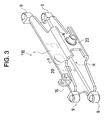
- FIG. 3 is a perspective view of the axle beam according to the preferred embodiment of the present invention;
- FIG. 4 is a cross-sectional view that is taken along the line I-I in FIG. 3;
- FIG. 5 is a perspective view illustrating a process for carving a beam out of a square pipe according to the preferred embodiment of the present invention;
- FIG. 6 is a perspective view of a process for fixedly connecting a boss and the like to the beam according to the preferred embodiment of the present invention;
- FIG. 7A is a perspective view of the axle beam according to a first alternative embodiment of the present invention;
- FIG. 7B is a cross-sectional view of a middle portion as seen in the longitudinal direction of the axle beam according to the first alternative embodiment of the present invention;
- FIG. 8A is a perspective view of the axle beam according to a second alternative embodiment of the present invention;
- FIG. 8B is a cross-sectional view of a middle portion as seen in the longitudinal direction of the axle beam according to the second alternative embodiment of the present invention;
- FIG. 9A is an exploded perspective view of an axle beam according to a prior art; and
- FIG. 9B is a cross-sectional view of a middle portion as seen in the longitudinal direction of the axle beam according to the prior art.
-
- A preferred embodiment of the present invention will now be described with reference to FIGS. 1 through 3.
- Now referring to FIG. 1, the drawing illustrates a plan view of an entire
rear axle device 100 provided on the rear side of a forklift truck according to the first preferred embodiment of the present invention. Therear axle device 100 has anaxle beam 110 and a pair of right andleft steering knuckles axle beam 110. - The
axle beam 110 includes abeam 1 extending laterally relative to the vehicle body and two pairs of upper andlower bosses 9 provided at the opposite ends of thebeam 1, as best seen in FIG. 3. The pairedbosses 9 on each side are located one above the other.Center pins 20 are welded to the front and rear surfaces of thebeam 1, respectively, and are located at the middle portion in the longitudinal direction (the longitudinally middle portion) of thebeam 1 between the opposite ends. Theaxle beam 110 is pivotally supported by a rear frame (not shown) of the vehicle body through thecenter pins 20. - As shown in FIG. 2, a
bracket 15 is fixedly connected to the top surface of thebeam 1 adjacent to one end of thebeam 1 in the longitudinal direction. Adamper device 14 is pivotally coupled at one end thereof to thebracket 15 and at the other end thereof to the rear frame of the vehicle body. - The paired
steering knuckles axle beam 110. Referring to FIG. 2 showing a cross-sectional rear end view of therear axle device 100, each of thesteering knuckles wheel spindle 8. Each of the kingpins 6 extends in the vertical direction (the upper and lower direction in FIG. 2) of the vehicle body. Each of thewheel spindles 8 protrudes from its associated kingpin 6 outward in the lateral direction of the vehicle body. The kingpins 6 of thesteering knuckles lower bosses 9 disposed at the opposite ends of theaxle beam 110, respectively. - The
wheel spindles 8 of thesteering knuckles steerable wheels knuckle arm 7 extends rearward from each of the kingpins 6. - A double acting
hydraulic cylinder 4 of a full hydraulicpower steering device 3 is mounted on the longitudinally middle portion (the laterally middle portion in FIG. 1) of theaxle beam 110. Thehydraulic cylinder 4 has acylinder rod 5 which is operable to be displaced in the lateral direction of the vehicle body. - Clevises (or connecting members) 10R, 10L are formed on the opposite ends of the
cylinder rod 5, respectively.Tie rods clevises knuckle arms 7 of thesteering knuckles 2R, respectively. - The structure of the full hydraulic
power steering device 3, which is known in the art, is operable to displace thecylinder rod 5 in the axial direction thereof by charging and discharging oil under pressure into and out of the double actinghydraulic cylinder 4 in response to the operation of a steering wheel (not shown) provided at operator's seat. As thecylinder rod 5 is displaced in either direction, one of thetie rods cylinder rod 5 through therespective clevises knuckle arm 7, and the other tie rod pulls theother knuckle arm 7. As a result, thesteering knuckles rear wheels - Thus, the
axle beam 110, thehydraulic cylinder 4, theclevises tie rods steering knuckles - Now referring to FIG. 4 showing a cross-section of the
beam 1 taken perpendicularly to the longitudinal direction of thebeam 1 of theaxle beam 110 along the line I-I of FIG. 3, thebeam 1 of theaxle beam 110 forms a closed rectangular shape at the middle thereof where the center pins 20 are fixed. That is, as shown in FIG. 4, thebeam 1 is shaped at its middle to form a space R which is surrounded by the front and rear and the top and bottom of thebeam 1. Thus, the tube structure of thebeam 1 increases the rigidity and hence ensures the strength required for thebeam 1. - In the preferred embodiment, the above described
hydraulic cylinder 4 is located in the space R which is surrounded by thebeam 1, as shown in FIG. 4. Consequently, the front and rear and the top and bottom of thehydraulic cylinder 4 is surrounded by thebeam 1, so that thehydraulic cylinder 4 is protected against breakage due to hitting from outside by a rock and the like. - Now referring to FIG. 5 illustrating the process of manufacturing the
beam 1 of theaxle beam 110, thebeam 1 is made by cutting from an elongatedsquare tube material 21 as a base material having a closed rectangular cross-section that is taken perpendicularly to the longitudinal direction of thebeam 1. Thesquare tube material 21 is cut intobeams 1 by fusion using a three dimensional plasma fusing apparatus (first manufacturing process). A three dimensional laser fusing apparatus is also applicable for fusing thesquare tube material 21. - The square tube material or the
base material 21 is made of metal and formed by extruding a bar material called billet. It is noted that thesquare tube material 21 may be made by bending a flat plate material and then welding the ends thereof to form a square tube. In this case, thebeam 1 has one welded portion in the cross-section thereof taken perpendicularly to the longitudinal direction of thebeam 1. For enhancing dimensional accuracy by reducing the number of welded portions, however, it is desirable to form a seamless tube by extrusion molding. - Thus forming a seamless tube by extrusion molding, the
beam 1 can be made free of welded portion which are relatively weak in strength as shown in FIG. 4, with the result that the strength of thebeam 1 is improved. In other words, even if thesquare tube material 21 is made relatively thin, the strength required for thebeam 1 is ensured, so that material cost, as well as manufacturing cost, is reduced. - As most clearly seen in FIG. 3, the
beam 1 is formed in such a way that only its middle portion between the opposite ends thereof is closed by four top, bottom, front and rear walls thereby to form the space R, while the remaining end portions are open on the rear side and taper-shaped toward the ends as seen from the top. - The tapered ends of the
beam 1 allow therear wheels axle beam 110, while ensuring the strength required for theaxle beam 110. - Furthermore, since the
beam 1 is tapered at the opposite ends where thebeam 1 is shaped thin, a plurality ofidentical beams 1 can be cut from a single elongated square tube material or abase material 21 with as little waste as possible by cutting along the cutting lines indicated by bold lines in FIG. 5, that is, a plurality of theidentical beams 1 is in staggered arrangement on the elongatedsquare tube material 21 for fusing. That is, the cutting lines (indicated by the bold line in FIG. 5) for fusing are determined in such a manner that the tapered ends of thecoadjacent beams 1 are arranged to vertically overlap relative to the longitudinal direction of the square tube. Thus, more number of thebeams 1 is manufactured from a bar of thesquare tube material 21, so that waste produced from thesquare pipe 21 is reduced. - By using the three dimensional plasma fusing apparatus (or the three dimensional laser fusing apparatus) as in the preferred embodiment, dimensional accuracy of the resulting
beam 1 is much improved over that obtainable by gas fusing and the like. The improved dimensional accuracy helps increase yield rate and hence reduce the manufacturing cost. - Now referring to FIG. 6 illustrating the second manufacturing process, the center pins 20, the
bracket 15 and thebosses 9 are welded to the cut outbeam 1. Thus, theaxle beam 110 shown in FIG. 3 is completed. - It is noted that, as shown in FIG. 6, cutout portions 1 g are formed on opposite sides of the
rear center pin 20 in such a manner that thebeam 1 is recessed in the lateral direction for a predetermined length. The formation of such cutout portions 1 g helps relieve the stress concentration which tends to occur during vehicle operation at positions of thebeam 1 which are indicated by dotted bold circles in FIG. 6. - The present invention is not limited to the embodiments described above but may be modified into the following alternative embodiments.
- Referring to FIG. 7A showing a first alternative embodiment, the
beam 1 includes afirst member 91 having a U-shaped cross-section perpendicular to the longitudinal direction of thebeam 1 and asecond plate member 92 which is welded to thefirst member 91. In other words, thebeam 1 is formed by two members. The firstU-shaped member 91 and thesecond plate member 92 are welded together in such a way that a space R surrounded by four walls as shown in FIG. 7B which is a cross-sectional view of FIG. 7A is formed in the resultingbeam 1. In this case, as shown in FIG. 7B, the resultingbeam 1 has two welded portions in the cross-section of the longitudinally middle portion thereof as indicated by two arrows. In this first alternative embodiment, the number of welded portions is two that is fewer than four welded portions of the prior art, so that the yield rate of material and dimensional accuracy are improved. - Referring to FIG. 8A showing a second alternative embodiment, the
beam 1 is formed in such a manner that afirst member 93 having an L-shaped cross-section perpendicular to the longitudinal direction of thebeam 1 is welded to asecond member 94 having a similar L-shaped cross-section perpendicular to the longitudinal direction of thebeam 1. In other words, thebeam 1 is formed by two members. The L-shapedmembers beam 1 which is surrounded by four walls as shown in FIG. 8B which is a cross-sectional view of FIG. 8A. In this case, as shown in FIG. 8B, there are two welded portions in the cross-section of the longitudinally middle portion of the resultingbeam 1. In the second alternative embodiment, the number of welded portions is two that is fewer than four welded portions of the prior art, so that the yield rate of material and dimensional accuracy are improved. - As mentioned above, the number of welded portions is not limited to 0 but may range from 0 to 2 that is fewer than four welded portions of the prior art.
- In the preferred embodiment, the present invention has been described by way of a rear axle beam of a forklift truck. As a matter of course, the present invention is also applicable to a front axle beam of a front steering vehicle. In addition, the present invention is not limited to application to a forklift truck, but it is applicable to other types of industrial vehicles.
- Therefore, the present examples and embodiments are to be considered as illustrative and not restrictive, and the invention is not to be limited to the details given herein but may be modified within the scope of the appended claims.
- An axle beam for an industrial vehicle has a beam and a boss. The beam is supported on a vehicle body. The boss is provided at opposite ends of the beam for supporting a kingpin. The beam includes at a longitudinally middle thereof a portion having a closed cross-section perpendicular to a longitudinal direction of the beam and is shaped at the portion to form a space which is surrounded by a front and rear and a top and bottom of the beam. The portion is formed by welding two members or by one tube member.
Claims (15)
- An axle beam for an industrial vehicle comprising a beam supported on a vehicle body and a boss provided at opposite ends of the beam for supporting a kingpin, characterized in that the beam includes at a longitudinally middle thereof a portion having a closed cross-section perpendicular to a longitudinal direction of the beam and is shaped at the portion to form a space which is surrounded by a front and rear and a top and bottom of the beam, and in that the portion is formed by welding two members or by one tube member.
- The axle beam according to claim 1, wherein the number of welded portions that appear in the cross-section ranging from 0 to 2.
- The axle beam according to claim 2, wherein the number of welded portions is 0.
- The axle beam according to any one of claims 1 through 3, wherein the beam is tapered at the opposite ends.
- The axle beam according to any one of claims 1 through 4, wherein the beam is formed by fusing a tube material.
- The axle beam according to claim 5, wherein the tube material is seamless.
- The axle beam according to any one of claims 1, 2, 4 and 5, wherein the beam is at least formed by two members welded to each other, whereby the space being surrounded by the front and rear and the top and bottom of the beam.
- The axle beam according to claim 7, wherein one of the two members has a U-shaped cross-section perpendicular to the longitudinal direction of the beam.
- The axle beam according to claim 7, wherein the two members each have an L-shaped cross-section perpendicular to the longitudinal direction of the beam.
- A rear steering device for an industrial vehicle comprising the axle beam as set forth in any one of claims 1 through 9, further comprising:a cylinder located in the space for power steering.
- A method of manufacturing an axle beam for an industrial vehicle having a beam and a boss, the beam including a tube portion while being supported on a vehicle body, the boss being connected to opposite ends of the beam in a longitudinal direction of the beam for supporting a kingpin, characterized by the steps of:fusing a tube material to form the beam in a first manufacturing process; andconnecting the boss to the beam in a second manufacturing process.
- The method of manufacturing the axle beam according to claim 11, wherein the first manufacturing process includes:forming the beam having the tube portion at a middle portion thereof in the longitudinal direction; andshaping the opposite ends of the beam thinner than the tube portion.
- The method of manufacturing the axle beam according to claim 12, wherein the first manufacturing process includes:producing a plurality of identical beams from one tube material; anddetermining a cutting line in staggered arrangement of the identical beams for fusing the tube material.
- The method of manufacturing the axle beam according to any one of claims 11 through 13, wherein the first manufacturing process includes fusing the tube material by using a three dimensional plasma fusing apparatus or a three dimensional laser fusing apparatus.
- The method of manufacturing the axle beam according to any one of claims 11 through 14, wherein the first manufacturing step includes utilizing the tube material of a seamless type.
Applications Claiming Priority (2)
| Application Number | Priority Date | Filing Date | Title |
|---|---|---|---|
| JP2003136916 | 2003-05-15 | ||
| JP2003136916A JP2004338872A (en) | 2003-05-15 | 2003-05-15 | Axle beam for industrial vehicle, its manufacturing method, and rear steering device |
Publications (3)
| Publication Number | Publication Date |
|---|---|
| EP1477330A2 true EP1477330A2 (en) | 2004-11-17 |
| EP1477330A3 EP1477330A3 (en) | 2008-11-26 |
| EP1477330B1 EP1477330B1 (en) | 2010-05-19 |
Family
ID=33028385
Family Applications (1)
| Application Number | Title | Priority Date | Filing Date |
|---|---|---|---|
| EP04011456A Expired - Fee Related EP1477330B1 (en) | 2003-05-15 | 2004-05-13 | Axle beam for industrial vehicle, method of manufacturing the same and rear steering apparatus |
Country Status (4)
| Country | Link |
|---|---|
| US (2) | US20040227395A1 (en) |
| EP (1) | EP1477330B1 (en) |
| JP (1) | JP2004338872A (en) |
| DE (1) | DE602004027191D1 (en) |
Cited By (2)
| Publication number | Priority date | Publication date | Assignee | Title |
|---|---|---|---|---|
| WO2017086898A3 (en) * | 2015-11-16 | 2017-06-22 | Coskunoz Metal Form Makina Endustri Ve Ticaret Anonim Sirketi | Production method of an axle mount bracket |
| CN112265416A (en) * | 2020-10-30 | 2021-01-26 | 浙江工业大学 | Heavy-duty forklift front drive axle housing based on triangular reinforcing structure |
Families Citing this family (12)
| Publication number | Priority date | Publication date | Assignee | Title |
|---|---|---|---|---|
| JP5578357B2 (en) | 2010-09-08 | 2014-08-27 | 株式会社ジェイテクト | Vehicle steering system |
| DE202012100213U1 (en) * | 2012-01-20 | 2013-04-23 | Hubtex Maschinenbau Gmbh & Co. Kg | Truck |
| US9724965B2 (en) * | 2012-04-20 | 2017-08-08 | Hendrickson Usa, L.L.C. | Fabricated vehicle axle |
| CN104442197B (en) * | 2013-09-18 | 2017-03-15 | 比亚迪股份有限公司 | Axle housing component for vehicle and the vehicle with it |
| US9824321B2 (en) * | 2013-09-20 | 2017-11-21 | Infosys Limited | System and method for categorization of social media conversation for response management |
| JP5791162B2 (en) * | 2014-02-04 | 2015-10-07 | ニチユ三菱フォークリフト株式会社 | Axle frame of electric power steering device |
| DE202016004580U1 (en) * | 2016-07-25 | 2016-10-27 | Liebherr-Werk Ehingen Gmbh | Axle |
| AT518918B1 (en) * | 2016-07-26 | 2020-01-15 | Bulmor Holding Gmbh | Vehicle with side lifting device |
| KR101852544B1 (en) | 2016-08-26 | 2018-04-26 | 이문주 | Forklift axle steering device capable of precision turning place |
| DE102019125792B4 (en) * | 2019-09-25 | 2021-12-16 | Crown Equipment Corp. | Electrically operated steering system for a vehicle |
| CN112091465B (en) * | 2020-09-21 | 2022-03-18 | 中联重科安徽工业车辆有限公司 | Method for manufacturing forklift body |
| CN113212069B (en) * | 2021-06-11 | 2022-04-08 | 中车眉山车辆有限公司 | Axle fixing device |
Citations (1)
| Publication number | Priority date | Publication date | Assignee | Title |
|---|---|---|---|---|
| JP2000016107A (en) | 1998-07-03 | 2000-01-18 | Toyota Autom Loom Works Ltd | Rear axle beam of industrial vehicle |
Family Cites Families (31)
| Publication number | Priority date | Publication date | Assignee | Title |
|---|---|---|---|---|
| US1899347A (en) * | 1929-05-15 | 1933-02-28 | Clark Equipment Co | Axle |
| US1873453A (en) * | 1930-04-07 | 1932-08-23 | Clark Equipment Co | Method of making a front axle |
| US2073035A (en) * | 1936-03-04 | 1937-03-09 | Bertis H Urschel | Tubular axle |
| US2911262A (en) * | 1955-07-01 | 1959-11-03 | Superior Steel & Malleable Cas | Vehicle axle |
| US3804467A (en) * | 1971-07-01 | 1974-04-16 | Lear Siegler Inc | Front axle |
| US3768585A (en) * | 1971-08-17 | 1973-10-30 | Eaton Corp | Steering axle |
| US4046218A (en) * | 1976-08-23 | 1977-09-06 | Towmotor Corporation | Floating steering axle |
| DE2642903A1 (en) * | 1976-09-24 | 1978-03-30 | Linde Ag | STEERING AXLE FOR A VEHICLE |
| DE2642902A1 (en) * | 1976-09-24 | 1978-03-30 | Linde Ag | STEERING AXLE FOR A FORK LIFT |
| JPS5424833A (en) | 1977-07-26 | 1979-02-24 | Mitsubishi Chem Ind Ltd | Polyoxyethylene glycol complex of rare earth element |
| US4361360A (en) * | 1979-03-05 | 1982-11-30 | Siegfried Kuether | Tube end forging process |
| EP0067606A1 (en) * | 1981-06-11 | 1982-12-22 | GKN Group Services Limited | Steering of vehicles |
| JPH02262401A (en) | 1989-04-03 | 1990-10-25 | Isuzu Motors Ltd | Hollow axle for vehicle |
| JP2678871B2 (en) | 1993-07-22 | 1997-11-19 | 中央紙器工業株式会社 | Foldable cardboard packing |
| US5429423A (en) * | 1994-01-07 | 1995-07-04 | Dana Corporation | Fabricated front axle I-beam |
| JPH09277433A (en) * | 1996-04-11 | 1997-10-28 | Shinsozai Hanbai Kk | Composite steel panel and its production |
| US5810377A (en) * | 1997-01-21 | 1998-09-22 | The Boler Company | Fabricated steer axle |
| US5865452C1 (en) * | 1997-03-05 | 2001-02-27 | Watson & Chalin Mfg Inc | Steerable suspension system |
| AU706372B2 (en) | 1997-04-25 | 1999-06-17 | Kabushiki Kaisha Toyoda Jidoshokki Seisakusho | Mounting structure for wheel angle detector and rotation amount detector for vehicle wheel |
| JP3918162B2 (en) * | 1997-11-28 | 2007-05-23 | 株式会社 神崎高級工機製作所 | Power steering device for vehicles |
| US6032967A (en) * | 1998-02-18 | 2000-03-07 | Dana Canada, Inc. | Axle and suspension connection assembly and method |
| US6078110A (en) * | 1998-03-12 | 2000-06-20 | Manvel Zakharian | Method of obtaining the adjustable capacitor |
| JP2000301251A (en) * | 1998-12-31 | 2000-10-31 | Dana Corp | Production of front wheel axle beam by hydroforming |
| US6412879B1 (en) * | 1999-11-10 | 2002-07-02 | Dana Corporation | Composite spring seat for an axle housing |
| US6416136B1 (en) * | 2000-02-23 | 2002-07-09 | Fred P. Smith | Lightweight, adjustable-height, axle |
| JP2001233063A (en) | 2000-02-23 | 2001-08-28 | Suzuki Motor Corp | Engine mount bracket |
| SE0101046L (en) * | 2001-03-23 | 2002-03-05 | Volvo Lastvagnar Ab | Hollow structural elements and method of manufacture |
| US6695351B2 (en) * | 2001-05-02 | 2004-02-24 | Meritor Heavy Vehicle Technology, Llc | Internal bulkhead for spring seat reinforcement |
| US6808189B1 (en) * | 2001-05-15 | 2004-10-26 | Dana Corporation | Steer axle assembly with inverted steering knuckle |
| US6609649B1 (en) * | 2001-07-13 | 2003-08-26 | Torque-Traction Technologies, Inc. | Method for manufacturing banjo-type axle housings |
| US6585331B2 (en) * | 2001-09-06 | 2003-07-01 | Meritor Heavy Vehicle Technology, Llc | Tubular axle beam |
-
2003
- 2003-05-15 JP JP2003136916A patent/JP2004338872A/en active Pending
-
2004
- 2004-05-11 US US10/842,745 patent/US20040227395A1/en not_active Abandoned
- 2004-05-13 DE DE602004027191T patent/DE602004027191D1/en not_active Expired - Lifetime
- 2004-05-13 EP EP04011456A patent/EP1477330B1/en not_active Expired - Fee Related
-
2008
- 2008-02-14 US US12/031,205 patent/US7763825B2/en not_active Expired - Fee Related
Patent Citations (1)
| Publication number | Priority date | Publication date | Assignee | Title |
|---|---|---|---|---|
| JP2000016107A (en) | 1998-07-03 | 2000-01-18 | Toyota Autom Loom Works Ltd | Rear axle beam of industrial vehicle |
Cited By (3)
| Publication number | Priority date | Publication date | Assignee | Title |
|---|---|---|---|---|
| WO2017086898A3 (en) * | 2015-11-16 | 2017-06-22 | Coskunoz Metal Form Makina Endustri Ve Ticaret Anonim Sirketi | Production method of an axle mount bracket |
| CN112265416A (en) * | 2020-10-30 | 2021-01-26 | 浙江工业大学 | Heavy-duty forklift front drive axle housing based on triangular reinforcing structure |
| CN112265416B (en) * | 2020-10-30 | 2024-05-03 | 浙江工业大学 | Heavy-load forklift front drive axle housing based on triangle reinforcing structure |
Also Published As
| Publication number | Publication date |
|---|---|
| DE602004027191D1 (en) | 2010-07-01 |
| US20040227395A1 (en) | 2004-11-18 |
| US7763825B2 (en) | 2010-07-27 |
| EP1477330B1 (en) | 2010-05-19 |
| EP1477330A3 (en) | 2008-11-26 |
| US20080142570A1 (en) | 2008-06-19 |
| JP2004338872A (en) | 2004-12-02 |
Similar Documents
| Publication | Publication Date | Title |
|---|---|---|
| US7763825B2 (en) | Axle beam for industrial vehicle, method of manufacturing the same and rear steering apparatus | |
| US8454041B2 (en) | Suspension arm unit for vehicle | |
| EP2310217B1 (en) | Cross-member for a rear twist-beam axle suspension for a motor vechicle and method for its production | |
| US6122948A (en) | Method of hydroforming a front axle beam | |
| JP3546564B2 (en) | Twist beam suspension | |
| TWI466797B (en) | Bicycle frame | |
| US20060158023A1 (en) | Continuous radius axle and fabricated spindle assembly | |
| US6609764B2 (en) | Fabricated vehicle axle | |
| US7195260B2 (en) | Steer axle suspension | |
| US3982604A (en) | Steering axle | |
| CN100522410C (en) | Reinforced section and method for manufacturing the same | |
| AU2004201660B2 (en) | Axle supporting structure for industrial vehicle and industrial vehicle having the same | |
| JP2008030513A (en) | Torsion beam, torsion beam type suspension, and method for manufacturing torsion beam | |
| US6516993B2 (en) | Control rod | |
| JPH0319114B2 (en) | ||
| JP6164967B2 (en) | Body frame for saddle-ride type vehicles | |
| EP2773473B1 (en) | Forged hollow axle and method for making the same | |
| US6641150B1 (en) | Fabricated steer axle assembly | |
| US4295779A (en) | Straight arm loader | |
| EP1522432A1 (en) | Suspension | |
| JPH02169312A (en) | Manufacture of arm member for vehicle suspension system | |
| JP2023131008A (en) | vehicle | |
| JP2021109573A (en) | Front axle beam and method for manufacture thereof | |
| JPH02124361A (en) | Rack shaft of rack and pinion type steering device | |
| JP2021109572A (en) | Front axle beam and method for manufacture thereof |
Legal Events
| Date | Code | Title | Description |
|---|---|---|---|
| PUAI | Public reference made under article 153(3) epc to a published international application that has entered the european phase |
Free format text: ORIGINAL CODE: 0009012 |
|
| 17P | Request for examination filed |
Effective date: 20040513 |
|
| AK | Designated contracting states |
Kind code of ref document: A2 Designated state(s): AT BE BG CH CY CZ DE DK EE ES FI FR GB GR HU IE IT LI LU MC NL PL PT RO SE SI SK TR |
|
| AX | Request for extension of the european patent |
Extension state: AL HR LT LV MK |
|
| PUAL | Search report despatched |
Free format text: ORIGINAL CODE: 0009013 |
|
| AK | Designated contracting states |
Kind code of ref document: A3 Designated state(s): AT BE BG CH CY CZ DE DK EE ES FI FR GB GR HU IE IT LI LU MC NL PL PT RO SE SI SK TR |
|
| AX | Request for extension of the european patent |
Extension state: AL HR LT LV MK |
|
| AKX | Designation fees paid |
Designated state(s): DE FR GB |
|
| GRAP | Despatch of communication of intention to grant a patent |
Free format text: ORIGINAL CODE: EPIDOSNIGR1 |
|
| GRAS | Grant fee paid |
Free format text: ORIGINAL CODE: EPIDOSNIGR3 |
|
| GRAA | (expected) grant |
Free format text: ORIGINAL CODE: 0009210 |
|
| AK | Designated contracting states |
Kind code of ref document: B1 Designated state(s): DE FR GB |
|
| REG | Reference to a national code |
Ref country code: GB Ref legal event code: FG4D |
|
| REF | Corresponds to: |
Ref document number: 602004027191 Country of ref document: DE Date of ref document: 20100701 Kind code of ref document: P |
|
| PLBE | No opposition filed within time limit |
Free format text: ORIGINAL CODE: 0009261 |
|
| STAA | Information on the status of an ep patent application or granted ep patent |
Free format text: STATUS: NO OPPOSITION FILED WITHIN TIME LIMIT |
|
| 26N | No opposition filed |
Effective date: 20110222 |
|
| REG | Reference to a national code |
Ref country code: DE Ref legal event code: R097 Ref document number: 602004027191 Country of ref document: DE Effective date: 20110221 |
|
| PGFP | Annual fee paid to national office [announced via postgrant information from national office to epo] |
Ref country code: FR Payment date: 20110603 Year of fee payment: 8 |
|
| PGFP | Annual fee paid to national office [announced via postgrant information from national office to epo] |
Ref country code: GB Payment date: 20110523 Year of fee payment: 8 |
|
| PGFP | Annual fee paid to national office [announced via postgrant information from national office to epo] |
Ref country code: DE Payment date: 20110530 Year of fee payment: 8 |
|
| GBPC | Gb: european patent ceased through non-payment of renewal fee |
Effective date: 20120513 |
|
| REG | Reference to a national code |
Ref country code: FR Ref legal event code: ST Effective date: 20130131 |
|
| REG | Reference to a national code |
Ref country code: DE Ref legal event code: R119 Ref document number: 602004027191 Country of ref document: DE Effective date: 20121201 |
|
| PG25 | Lapsed in a contracting state [announced via postgrant information from national office to epo] |
Ref country code: GB Free format text: LAPSE BECAUSE OF NON-PAYMENT OF DUE FEES Effective date: 20120513 Ref country code: FR Free format text: LAPSE BECAUSE OF NON-PAYMENT OF DUE FEES Effective date: 20120531 |
|
| PG25 | Lapsed in a contracting state [announced via postgrant information from national office to epo] |
Ref country code: DE Free format text: LAPSE BECAUSE OF NON-PAYMENT OF DUE FEES Effective date: 20121201 |