EP1477229A1 - Water spray plate, and shower head - Google Patents
Water spray plate, and shower head Download PDFInfo
- Publication number
- EP1477229A1 EP1477229A1 EP03706970A EP03706970A EP1477229A1 EP 1477229 A1 EP1477229 A1 EP 1477229A1 EP 03706970 A EP03706970 A EP 03706970A EP 03706970 A EP03706970 A EP 03706970A EP 1477229 A1 EP1477229 A1 EP 1477229A1
- Authority
- EP
- European Patent Office
- Prior art keywords
- water spray
- water
- spray holes
- shower
- holes
- Prior art date
- Legal status (The legal status is an assumption and is not a legal conclusion. Google has not performed a legal analysis and makes no representation as to the accuracy of the status listed.)
- Granted
Links
Images


Classifications
-
- B—PERFORMING OPERATIONS; TRANSPORTING
- B05—SPRAYING OR ATOMISING IN GENERAL; APPLYING FLUENT MATERIALS TO SURFACES, IN GENERAL
- B05B—SPRAYING APPARATUS; ATOMISING APPARATUS; NOZZLES
- B05B1/00—Nozzles, spray heads or other outlets, with or without auxiliary devices such as valves, heating means
- B05B1/14—Nozzles, spray heads or other outlets, with or without auxiliary devices such as valves, heating means with multiple outlet openings; with strainers in or outside the outlet opening
- B05B1/18—Roses; Shower heads
-
- B—PERFORMING OPERATIONS; TRANSPORTING
- B05—SPRAYING OR ATOMISING IN GENERAL; APPLYING FLUENT MATERIALS TO SURFACES, IN GENERAL
- B05B—SPRAYING APPARATUS; ATOMISING APPARATUS; NOZZLES
- B05B1/00—Nozzles, spray heads or other outlets, with or without auxiliary devices such as valves, heating means
- B05B1/14—Nozzles, spray heads or other outlets, with or without auxiliary devices such as valves, heating means with multiple outlet openings; with strainers in or outside the outlet opening
- B05B1/18—Roses; Shower heads
- B05B1/185—Roses; Shower heads characterised by their outlet element; Mounting arrangements therefor
-
- B—PERFORMING OPERATIONS; TRANSPORTING
- B05—SPRAYING OR ATOMISING IN GENERAL; APPLYING FLUENT MATERIALS TO SURFACES, IN GENERAL
- B05B—SPRAYING APPARATUS; ATOMISING APPARATUS; NOZZLES
- B05B1/00—Nozzles, spray heads or other outlets, with or without auxiliary devices such as valves, heating means
- B05B1/14—Nozzles, spray heads or other outlets, with or without auxiliary devices such as valves, heating means with multiple outlet openings; with strainers in or outside the outlet opening
- B05B1/18—Roses; Shower heads
- B05B1/182—Roses; Shower heads characterised by their outlet openings or elements; Mounting arrangements therefor
- B05B1/1821—Roses; Shower heads characterised by their outlet openings or elements; Mounting arrangements therefor the outlet openings arranged in plural groups or rows
- B05B1/1825—Roses; Shower heads characterised by their outlet openings or elements; Mounting arrangements therefor the outlet openings arranged in plural groups or rows with three or more dissimilar groups or rows
-
- B—PERFORMING OPERATIONS; TRANSPORTING
- B05—SPRAYING OR ATOMISING IN GENERAL; APPLYING FLUENT MATERIALS TO SURFACES, IN GENERAL
- B05B—SPRAYING APPARATUS; ATOMISING APPARATUS; NOZZLES
- B05B1/00—Nozzles, spray heads or other outlets, with or without auxiliary devices such as valves, heating means
- B05B1/14—Nozzles, spray heads or other outlets, with or without auxiliary devices such as valves, heating means with multiple outlet openings; with strainers in or outside the outlet opening
- B05B1/18—Roses; Shower heads
- B05B1/182—Roses; Shower heads characterised by their outlet openings or elements; Mounting arrangements therefor
- B05B1/1821—Roses; Shower heads characterised by their outlet openings or elements; Mounting arrangements therefor the outlet openings arranged in plural groups or rows
- B05B1/1823—Concentric or coaxial groups
- B05B1/1824—Concentric or coaxial groups the outlet openings traversing a concavo-convex outlet wall
Definitions
- the present invention relates to a structure of a water spray plate for spraying shower water that is mounted to particularly a tip end of a shower head as one used in shower rooms, bathrooms, wash sinks or in barbershops and beauty salons.
- a shower head is generally arranged in that a water spray plate is mounted to a tip end of a main body of the shower head that is connected to a shower hose.
- a plurality of small water spray holes of identical size opens on the water spray plate. Water or hot water supplied through the shower hose passes through a main body of the shower hose and is split through the plurality of water spray holes formed on the water spray plate. Through these water spray holes, small streams of water, that is, shower water, is respectively discharged.
- a generally used conventional shower head was arranged to have a diameter of the water spray holes of the water spray plate of approximately 0.8 mm to 1.0 mm, to have a number of holes of approximately 60 to 100, and to have an entire aperture area of approximately 40 mm 2 to 65 mm 2 .
- shower heads referred to as water-saving type shower heads are being sold in these days. More particularly, various measures are taken for saving the amount of water when using the shower.
- Japanese Unexamined Patent Publication No. 8-266940 suggests a shower head provided with a water flow portion of narrow diameter having a shape in which its outlet side is widened in diameter in the interior of a head portion.
- special parts are required for forming the water flow portion of narrow diameter in this prior art example so that inconveniences such as increases in manufacturing costs are caused.
- the entire aperture area of the water spray holes shall be generally made small for reducing the amount of water when using the shower.
- the number of water spray holes or the diameter of the respective water spray holes shall be reduced.
- Plus ion and minus ion are present in air in a balanced manner.
- the amount of plus ion in air tends to be increased while reductions in minus ions are observed.
- a large amount of minus ion is observed in air when being in woodlands or hot-spring areas and when close to waterfalls and fountains. In such circumstances in which the amount of minus ion in air is large, it is said that there is beneficial effect on work efficiency, amenity, weariness and healing of human beings.
- Minus ion is generated by large amounts when close to waterfalls, wherein minus ion is generated when dropping water is crushed. It is said that the amount of minus ion within air is accordingly increased in its periphery and this is also known to be a Lenard effect. Such a Lenard effect can be similarly obtained through shower water and minus ion was generated also when using conventional shower heads.
- a water spray plate in which the number of water spray holes is not less than 130, in which a diameter of the respective water spray holes not less than 0.1 mm and not more than 0.5 mm, and in which an entire aperture area of the water spray holes is not more than 30 mm 2 .
- such a water spray plate is arranged in that the entire aperture area of the water spray holes is not more than 30 mm 2 , the aperture area is smaller when compared to prior art examples and the amount of flowing water is reduced so that it is possible to achieve water-saving effects.
- the number of water spray holes is not less than 130 and the diameter of the respective water spray holes is not less than 0.1 mm and not more than 0.5 mm, the number of holes is larger and the water spray holes smaller when compared to prior art examples. Accordingly, a large amount of narrow water will be sprayed from the respective water spray holes at a large flow rate so that it is possible to achieve high cleaning effects and the sense of using the shower can be satisfied.
- the number of water spray holes of the water spray plate of the present invention is large, the number of spraying of the shower will become larger so that the number of striking water is increased. Accordingly, water is crushed so that small particles may be easier generated by a large amount so that the amount of generated minus ion is consequently increased.
- the number of water spray holes is not less than 150 and not more than 350.
- the diameter of the water spray holes is set to be not less than 0.1 mm and not more than 0.5 mm, sprayed water discharged from the respective holes will become narrow. When such sprayed water is struck, water may be even easier crushed so that the amount of generated minus ion is also increased.
- the size of the water spray holes is desirably not less than 0.2 mm and not more 0.4 mm in view of relation with the plate thickness of the water spray plate.
- a water spray plate in which a plurality of first water spray holes is provided in a central portion in a concentrated manner and in which a plurality of second water spray holes is annularly arranged in the periphery thereof.
- a large amount of water is sprayed from the plurality of first water spray holes formed in the central portion in a concentrated manner. It is accordingly possible to supply a large amount of water to a portion to be washed and to obtain high cleaning effects.
- the second water spray holes disposed annularly at positions located closer to the outer periphery of the water spray plate jet water to outer peripheral portions of the region of water that is jetted to the portion to be washed.
- the second water spray holes are arranged concentrically as a plurality of lines. Accordingly, the way of the water expands may be made uniform.
- the second water spray holes are arranged to be larger in diameter than that of the first water spray holes that are concentrated in the center.
- a surface of the water spray plate on which the second water spray holes are formed is bent or inclined such that shower water expands outward.
- the water spray plate is formed of a metallic thin plate on which the water spray holes are formed through photo-etching. With this arrangement, it is possible to easily manufacture a water spray plate formed with a plurality of small water spray holes.
- a shower head in which the above water spray plate is mounted to a main body of the shower head.
- the shower head comprises the advantages exhibited by the water spray plate.
- a spraying speed of sprayed water discharged through the water spray holes is not less than 20 km/h where the amount of conducted water is 10 liter per minute.
- the striking energy of sprayed water will become large. Accordingly, the water can be easily crushed minutely at the time of striking whereby small particles of water are generated by a large amount, and the amount of generated minus ion is accordingly increased.
- a plurality of water spray holes of small diameter is formed on the water spray plate and the entire aperture area of the water spray holes is reduced, it is possible to exhibit water-saving effects.
- sprayed water may be easily crushed when struck and the amount of generated minus ion is increased.
- first water spray holes When the first water spray holes are formed in the central portion of the water spray plate in a concentrated manner, a large amount of water will be sprayed from the central portion of the water spray plate in a concentrated manner so that a large amount of water may be supplied to a portion to be washed to thereby exhibit high washing effects.
- second water spray holes are annularly disposed in the periphery of the first water spray holes, water will also be discharged to an outer peripheral region of water that is jetted out from the first water spray holes. With this arrangement, it is possible to achieve expansion of shower water so as to satisfy the sense of using the shower.
- FIG. 1 is a side view illustrating a part of a shower head in a sectional manner
- FIG. 2 is a front view of a water spray plate
- FIG. 3 is a sectional view of the water spray plate.
- a main body of the shower head 1 as illustrated in FIG. 1 comprises a grip portion 2 and a head portion 3.
- the grip portion 2 and the head portion 3 are made of synthetic resin, and are connected together through means such as screw joint or bayonet joint (not shown) in a freely attachable/detachable manner.
- the grip portion 2 is of hollow cylindrical shape and includes a feed port 4 at one end thereof.
- the feed port 4 is connected to a shower hose 4a (only a part thereof is illustrated).
- the shower hose 4a is connected, as conventionally known, to a hydrant cock or a mixing cock or similar.
- the head portion 3 is connected to the other end of the grip 2.
- the head portion 3 includes a substantially L-shaped hollow space wherein its one end is connected to an interior space of the grip portion 2 while a discharge outlet 5 opens at the other end thereof.
- a water spray plate 6 is mounted to the discharge outlet 5.
- the water spray plate 6 is mounted to the head portion 3 in a freely attachable/detachable manner through a clamp ring 7 and is maintained in a watertight manner through a seal member 8 such as rubber.
- the water spray plate 6 will now be explained.
- the water spray plate 6 is made of a thin plate of stainless steel.
- the stainless steel thin plate is disk-like, having a plate thickness of approximately 0.4 mm and a diameter of approximately 50 mm.
- a plurality of water spray holes 9a, 9b are formed on such a stainless steel water spray plate 6.
- the diameter of the respective water spray holes is not less than 0.1 mm and not more than 0.5 mm.
- the water spray holes 9a, 9b are arranged as illustrated in FIG. 2. More particularly, a plurality of first water spray holes 9a is formed in a central portion of the water spray plate 6 in a concentrated manner. The diameter of the water spray holes 9a of the central portion is 0.32 mm. Total 80 to 150 of such water spray holes 9a open within a circle having a diameter of approximately 15 mm in the central portion of the water spray plate 6. More concretely, total 144 of water spray holes 9a open while creating 5 water spray hole rows. The entire aperture area of the first water spray holes 9a is 11.57 mm 2 .
- a plurality of second water spray holes 9b are annularly disposed around the first water spray holes 9a.
- the diameter of the water spray holes 9b is 0.37 mm.
- the second water spray holes 9b are arranged on two concentric rows as water spray hole rows 10a, 10b.
- the inner water spray hole row 10a is provided with total 18 water spray holes 9b on a circumference of a diameter of 30 mm.
- the outer water spray hole row 10b is provided with total 72 water spray holes 9b on a circumference of a diameter of 35 mm. Accordingly, the number of water spray holes 10a, 10b is total 90.
- the entire aperture area of the second water spray holes 9b is 9.67 mm 2 .
- the entire aperture area of the water spray holes 9a, 9b of the entire water spray plate is 21.24 mm 2 .
- the water spray plate 6 is arranged in that its central portion forms a flat surface while the periphery thereof includes a bent surface 6a, and it is as a whole formed in a dish-shaped manner that bulges forward.
- the first water spray holes 9a are provided on the flat surface at the central portion of the water spray plate 6.
- the second water spray holes 9b (water spray hole rows 10a, 10b) are formed at the bent surface 6a at the periphery of the water spray plate 6.
- the water spray plate 6 is arranged in that the respective water spray holes 9a, 9b are small holes and in that they are partially disposed at high density, drawbacks are presented in that hole forming through drilling or similar require a good deal of trouble. Moreover, when employing die forming through resin, the molds will be of complicated shape and the life of the molds will become shorter as well. For such reasons, the water spray plate 6 of the present embodiment is manufactured of a stainless steel thin plate that undergoes photo-etching.
- the main body of the shower head 1 is connected to the shower hose 4a.
- tap water or hot water
- the water runs from the feed port 4 at the lower end of the grip portion 2 through the grip portion 2 to reach the head portion 3, and it is simultaneously sprayed through the first water spray holes 9a and the second water spray holes 9b of the water spray plate 6 formed at the discharge outlet 5 as shower water.
- the water spray plate 6 of the present embodiment is arranged in that total 144 of the first water spray holes 9a having a diameter of 0.32 mm are formed and in that total 90 of the second water spray holes 9b having a diameter of 0.37 mm are formed. Accordingly, the entire aperture area of the water spray holes 9a, 9b is 21.24 mm 2 . As it will be described later in details, the water spray plate 6 of the present embodiment exhibits higher water-saving effects when compared to conventional shower heads, and it is possible to reduce the amount of conducted water per unit time.
- the water spray plate 6 is provided with total 144 of the first water spray holes 9a having a diameter of 0.32 mm that are concentrated at the central portion thereof, water is sprayed from the central portion of the water spray plate 6 in a concentrated manner as illustrated by the broken line. Accordingly, since a large amount of water is sprayed from the central portion of the water spray plate 6, this will form a water jet so that a large amount of water is supplied to a portion to be washed. It is accordingly possible to obtain sufficient cleaning effects.
- shower water is sprayed from the periphery of the central portion of the water spray plate 6 through the sprinkling water rows 10a, 10b of the second water spray holes 9b disposed annularly. Accordingly, water is discharged towards the outer peripheral portion of the region of water hitting the central portion of a portion to be washed, and this will lead to the expansion of the shower water. Since shower water is discharged also to the peripheral portion of a portion to be washed, the sense of using the shower is improved and the external appearance of shower water is also improved.
- the water spray hole rows 10a, 10b arranged in an annular manner is arranged in that total 90 of the water spray holes 9b having a diameter of 0.37 mm are formed and in that the water spray holes 9b are formed in a diversified manner of two rows. Accordingly, the distribution of shower water sprayed to the periphery will be uniform and it will also be possible to secure some amount of water for the periphery and to obtain a favorable external appearance of the shower.
- the second water spray holes 9b are of a diameter that is larger than that of the first water spray holes 9a.
- the amount of jet stream hitting at the central portion in a concentrated manner and the amount of shower water hitting its periphery will be well balanced. Supposing that the amount of water of the central jet stream is large, one might feel that he or she is only submitted to the jet stream and the sense of taking a shower will become weak. On the other hand, when the amount of shower water in the periphery becomes large, a sense of pressure of totally being submitted to water will become weak so that one might feel somewhat disappointed.
- the water spray plate 6 of the present embodiment is arranged in that the surface formed with the water spray hole rows 10a, 10b of the second water spray holes 9b forms a bent surface 6a, shower water will be expanded to the exterior so that the diffusiveness of shower water is further improved.
- the present invention is effective when applied to a so-called water-saving type water spray plate having a total number of water spray holes 9a, 9b of not less than 130, having a diameter of the respective water spray holes 9a, 9b of not less than 0.1 mm and not more than 0.5 mm, and having an entire aperture area of the water spray holes 9a, 9b of not more than 30 mm 2 .
- the water-saving effects will be explained.
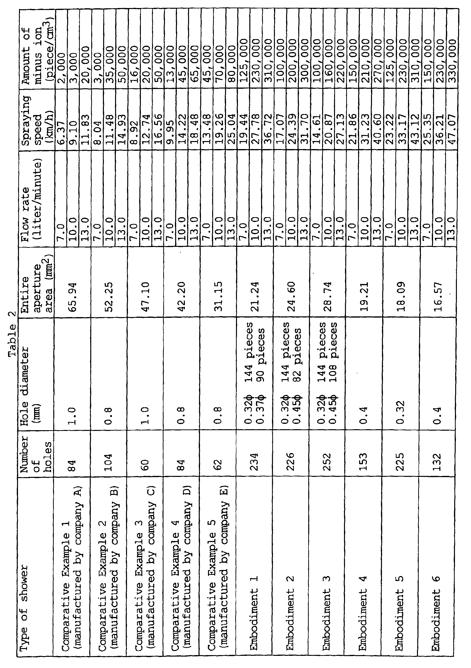
- the present Embodiment 1 exhibits water-saving effects of 69% when compared to the conventional Comparative Example 1.
- the shower head of the present Embodiment 1 is arranged in that the number of water spray holes 9a, 9b formed on the water spray plate 6 is total 234, and thus, the number of holes is remarkably larger than that of conventional shower heads.
- the number of sprayed streams sprayed from the water spray plate will accordingly be increased and when water hits the skin or the head portion of a human body, chances that particles of water hit with each other will be increased. Droplets and particles of water will thus be minutely crushed in an easier manner and minute particles of water will be generated by a large amount.
- the Lenard effect may be achieved through generation of minus ion when droplets crush. Accordingly, when minute particles of water are generated by a large amount through striking of water, the amount of minus ion in air will consequently be increased.
- the above embodiment is arranged in that not only the number of water spray holes 9a, 9b is large but also the sizes of the holes are smaller than those of the prior art with the diameters being 0.32 mm and 0.37 mm. Due to this fact, water sprayed from the respective water spray holes 9a, 9b will be narrow streams. Therefore, when water hits the skin or the head portion of a human body, more minute particles of water may be generated by a large amount through the narrow streams of water. Therefore, it is possible to exhibit the Lenard effect and to generate a large amount of minus ion.
- the shower head of Embodiment 1 is arranged in that the entire aperture area of the water spray holes 9a, 9b opening on the water spray plate 6 is 21.24 mm 2 and is thus smaller than those of conventional shower heads.
- the spraying speed of water sprayed through the water spray holes 9a, 9b will accordingly be larger when compared to those of conventional shower heads.
- the striking speed when sprayed water hits the skin or the head portion of a human body will thus be larger, and water will be minutely crushed through the large striking energy. Since the striking energy is large, droplets hitting the striking surface will be crushed and more easily spread, and the rate of spread droplets repeatedly striking other droplets will also be increased.
- the amounts of minus ion illustrated in Table 2 are values obtained when various shower heads were connected to a shower hose and the amounts of minus ion generated through shower water sprayed from the shower heads and striking against a plate disposed to be 40 cm apart from the shower heads were measured by using a minus ion measuring device.
- the measuring device was a minus ion measuring device of type CI-1000 capable of measuring the amount of generated minus ion per cm 3 .
- Such conventional shower heads included a small number of water spray holes while the size of the holes was not less than 0.8 mm, and the entire aperture area is large as a whole.
- the maximum amount of generated minus ion was not more than 80,000 pieces/ cm 3 also at a maximum flow rate of 13 liters/minute.
- the amount of generated minus ion was not less than 125,000 pieces/cm 3 also at a flow rate of 7 liters/minute, and an amount of generated minus ion of even 310,000 pieces/cm 3 was counted when the flow rate was 13 liters/minute, and it was accordingly confirmed that the amount of generated minus ions was remarkably large.
- the amounts of generated minus ion were respective measured upon changing the numbers and sizes of water spray holes, wherein the number of water spray holes was not less than 130 and the diameter of the holes 0.32 mm to 0.45 mm. Also in the Embodiments 2 to 6, the amounts of generated minus ion respectively exceeded 100,000 pieces/cm 3 and it was confirmed that a large amount of minus ion could be generated.
- FIG. 4 The relationship between the spraying speed and the amount of minus ion of Table 2 is illustrated in FIG. 4. As it can be understood from the approximation line of FIG. 4, when the total number of water spray holes is not less than 130, the diameter of the respective water spray holes not less than 0.1 mm and not more than 0.5 mm, the entire aperture area of the water spray holes not more than 30 mm 3 and the spraying speed not less than 20 km/h when the flow rate is 10 liters/minute, the amount of generated minus ion will exceed 100,000 pieces/cm 3 . Based on this fact, the spraying speed is desirably not less than 20 km/h when the flow rate is 10 liters/minute.
- the entire aperture area of the water spray holes is desirably not more than 30 mm 2 and not less than 15 mm 2 .
- the above water spray plate 6 of the present Embodiment 1 is formed of a stainless steel plate and is manufactured through photo-etching. Accordingly, a plurality of first water spray holes 9a may be easily disposed at high density at the central portion. Supposing that one tries to form water spray holes of the same density by using synthetic resin, it will be necessary to accurately form small needle-like projections at the forming molds. Such molds are difficult to be manufactured and also exhibit problems that the needle-like projections are easily broken, and manufacture through photo-etching is thus advantaged.
- the surface for forming the water spray hole rows 10a, 10b thereon is not limited to a bent surface but may also be a conical surface.
- the water spray hole rows does not necessarily be of double arrangement but may also be of single or of triple arrangement.
- the minimum diameter of the water spray holes is not particularly limited as long as they can be processes, it is desirably not less than 0.1 mm and more preferably not less than 0.2 mm in view of plate thickness and workability of photo-etching.
- the water spray plate of the present invention may be utilized for shower heads used in shower rooms, bathrooms, wash sinks or in barbershops and beauty salons.
Landscapes
- Nozzles (AREA)
- Bathtubs, Showers, And Their Attachments (AREA)
- Catching Or Destruction (AREA)
- Massaging Devices (AREA)
- Cleaning Implements For Floors, Carpets, Furniture, Walls, And The Like (AREA)
Abstract
Description

Claims (8)
- A water spray plate having a number of water spray holes (9a, 9b) of not less than 130, having a diameter of the respective water spray holes (9a, 9b) of not less than 0.1 mm and not more than 0.5 mm, and having an entire aperture area of the water spray holes (9a, 9b) of not more than 30 mm2.
- The water spray plate according to claim 1, characterized in that a plurality of first water spray holes (9a) is formed at a central portion in a concentrated manner and in that a plurality of second water spray holes (9b) is annularly formed in a periphery of the first water spray holes (9a).
- The water spray plate according to claim 2, characterized in that the second water spray holes (9b) are arranged concentrically as a plurality of water spray hole rows (10a, 10b).
- The water spray plate according to claim 2 or 3, characterized in that a diameter of the second water spray holes (9b) is larger than a diameter of the first water spray holes (9a).
- The water spray plate according to claim 2 or 3, characterized in that a surface (6a) on which the annular water spray hole rows (10a, 10b) of the second water spray holes (9b) are formed is shaped to be bent or inclined such that water output from the water spray hole rows (10a, 10b) expands outward.
- The water spray plate according to any one of claims 1 to 3, characterized in that the water spray holes (9a, 9b) are formed by performing photo-etching on a metallic thin plate.
- A shower head comprised with a water spray plate (6) provided at one end of a main body of the shower head (1) and with a shower hose (4a) being connected to the other end thereof, characterized in that the water spray plate (6) is the water spray plate according to any one of claims 1 to 3.
- The shower head according to claim 7, characterized in that a spraying speed of spraying water discharged from the water spray holes (9a, 9b) is not less than 20 km/h when an amount of conducted water is 10 liters/minute.
Applications Claiming Priority (5)
| Application Number | Priority Date | Filing Date | Title |
|---|---|---|---|
| JP2002093253 | 2002-02-22 | ||
| JP2002093253 | 2002-02-22 | ||
| JP2002099369 | 2002-02-26 | ||
| JP2002099369 | 2002-02-26 | ||
| PCT/JP2003/001807 WO2003070380A1 (en) | 2002-02-22 | 2003-02-19 | Water spray plate, and shower head |
Publications (3)
| Publication Number | Publication Date |
|---|---|
| EP1477229A1 true EP1477229A1 (en) | 2004-11-17 |
| EP1477229A4 EP1477229A4 (en) | 2008-01-02 |
| EP1477229B1 EP1477229B1 (en) | 2010-01-20 |
Family
ID=27759759
Family Applications (1)
| Application Number | Title | Priority Date | Filing Date |
|---|---|---|---|
| EP03706970A Expired - Lifetime EP1477229B1 (en) | 2002-02-22 | 2003-02-19 | Water spray plate, and shower head |
Country Status (11)
| Country | Link |
|---|---|
| US (1) | US7004409B2 (en) |
| EP (1) | EP1477229B1 (en) |
| JP (1) | JPWO2003070380A1 (en) |
| KR (1) | KR20040088460A (en) |
| CN (1) | CN100337756C (en) |
| AT (1) | ATE455597T1 (en) |
| AU (1) | AU2003211302A1 (en) |
| CA (1) | CA2470822C (en) |
| DE (1) | DE60331044D1 (en) |
| TW (1) | TWI251482B (en) |
| WO (1) | WO2003070380A1 (en) |
Cited By (2)
| Publication number | Priority date | Publication date | Assignee | Title |
|---|---|---|---|---|
| EP2777819A1 (en) * | 2013-03-14 | 2014-09-17 | Kohler Co. | Splashless spray head |
| US9707572B2 (en) | 2015-12-18 | 2017-07-18 | Kohler Co. | Multi-function splashless sprayhead |
Families Citing this family (42)
| Publication number | Priority date | Publication date | Assignee | Title |
|---|---|---|---|---|
| US7114666B2 (en) | 2002-12-10 | 2006-10-03 | Water Pik, Inc. | Dual massage shower head |
| US7740186B2 (en) * | 2004-09-01 | 2010-06-22 | Water Pik, Inc. | Drenching shower head |
| KR100709731B1 (en) | 2005-07-14 | 2007-04-19 | 주식회사 케이엔텍 | Water Saving Device for Shower |
| US8733675B2 (en) | 2006-04-20 | 2014-05-27 | Water Pik, Inc. | Converging spray showerhead |
| US20070272770A1 (en) * | 2006-05-26 | 2007-11-29 | Water Pik, Inc. | Apparatus and methods for a showerhead bracket with integral showerhead |
| US20080083844A1 (en) * | 2006-10-09 | 2008-04-10 | Water Pik, Inc. | Showerhead attachment assembly |
| US7789326B2 (en) | 2006-12-29 | 2010-09-07 | Water Pik, Inc. | Handheld showerhead with mode control and method of selecting a handheld showerhead mode |
| US8020787B2 (en) * | 2006-11-29 | 2011-09-20 | Water Pik, Inc. | Showerhead system |
| US8794543B2 (en) | 2006-12-28 | 2014-08-05 | Water Pik, Inc. | Low-speed pulsating showerhead |
| US7770822B2 (en) | 2006-12-28 | 2010-08-10 | Water Pik, Inc. | Hand shower with an extendable handle |
| US8366024B2 (en) * | 2006-12-28 | 2013-02-05 | Water Pik, Inc. | Low speed pulsating showerhead |
| US8371618B2 (en) | 2007-05-04 | 2013-02-12 | Water Pik, Inc. | Hidden pivot attachment for showers and method of making same |
| USD590048S1 (en) | 2007-12-20 | 2009-04-07 | Water Pik, Inc. | Hand shower |
| USD605731S1 (en) | 2007-12-26 | 2009-12-08 | Water Pik, Inc. | Bracket for hand shower |
| USD624156S1 (en) | 2008-04-30 | 2010-09-21 | Water Pik, Inc. | Pivot ball attachment |
| CA2678769C (en) | 2008-09-15 | 2014-07-29 | Water Pik, Inc. | Shower assembly with radial mode changer |
| USD600777S1 (en) | 2008-09-29 | 2009-09-22 | Water Pik, Inc. | Showerhead assembly |
| USD616061S1 (en) | 2008-09-29 | 2010-05-18 | Water Pik, Inc. | Showerhead assembly |
| USD606623S1 (en) | 2008-09-29 | 2009-12-22 | Water Pik, Inc. | Hand shower |
| USD625776S1 (en) | 2009-10-05 | 2010-10-19 | Water Pik, Inc. | Showerhead |
| US8616470B2 (en) | 2010-08-25 | 2013-12-31 | Water Pik, Inc. | Mode control valve in showerhead connector |
| EP2613887A4 (en) * | 2010-09-09 | 2014-09-17 | Wells Gelven Fractal Technology Llc | Fractal orifice plate |
| USD678467S1 (en) | 2012-01-27 | 2013-03-19 | Water Pik, Inc. | Ring-shaped handheld showerhead |
| USD678463S1 (en) | 2012-01-27 | 2013-03-19 | Water Pik, Inc. | Ring-shaped wall mount showerhead |
| CA2976867C (en) | 2012-06-22 | 2021-03-02 | Water Pik, Inc. | Bracket for showerhead with integral flow control |
| US9404243B2 (en) | 2013-06-13 | 2016-08-02 | Water Pik, Inc. | Showerhead with turbine driven shutter |
| USD744612S1 (en) | 2014-06-13 | 2015-12-01 | Water Pik, Inc. | Handheld showerhead |
| USD744614S1 (en) | 2014-06-13 | 2015-12-01 | Water Pik, Inc. | Wall mount showerhead |
| USD744064S1 (en) | 2014-06-13 | 2015-11-24 | Water Pik, Inc. | Handheld showerhead |
| USD744066S1 (en) | 2014-06-13 | 2015-11-24 | Water Pik, Inc. | Wall mount showerhead |
| USD745111S1 (en) | 2014-06-13 | 2015-12-08 | Water Pik, Inc. | Wall mount showerhead |
| USD744065S1 (en) | 2014-06-13 | 2015-11-24 | Water Pik, Inc. | Handheld showerhead |
| USD744611S1 (en) | 2014-06-13 | 2015-12-01 | Water Pik, Inc. | Handheld showerhead |
| JP6641674B2 (en) * | 2015-03-26 | 2020-02-05 | Toto株式会社 | Water spouting device |
| USD803981S1 (en) | 2016-02-01 | 2017-11-28 | Water Pik, Inc. | Handheld spray nozzle |
| CN108883426B (en) | 2016-02-01 | 2021-04-27 | 洁碧有限公司 | Handheld pet spray wand |
| US10265710B2 (en) | 2016-04-15 | 2019-04-23 | Water Pik, Inc. | Showerhead with dual oscillating massage |
| USD970684S1 (en) | 2016-04-15 | 2022-11-22 | Water Pik, Inc. | Showerhead |
| WO2018049213A1 (en) | 2016-09-08 | 2018-03-15 | Water Pik, Inc. | Pause assembly for showerheads |
| DE102016225987A1 (en) * | 2016-12-22 | 2018-06-28 | Hansgrohe Se | Effervescent spray outlet device and shower equipped therewith |
| USD843549S1 (en) | 2017-07-19 | 2019-03-19 | Water Pik, Inc. | Handheld spray nozzle |
| USD872227S1 (en) | 2018-04-20 | 2020-01-07 | Water Pik, Inc. | Handheld spray device |
Family Cites Families (15)
| Publication number | Priority date | Publication date | Assignee | Title |
|---|---|---|---|---|
| US1895307A (en) * | 1930-07-10 | 1933-01-24 | Beck Emil | Spray |
| US2860920A (en) * | 1956-10-02 | 1958-11-18 | Harold E Waller | Shower head construction |
| US3037710A (en) * | 1960-11-21 | 1962-06-05 | Kusznier Steve | Waterite |
| US4056229A (en) * | 1976-04-27 | 1977-11-01 | Jones Genevieve M | Car wash sprayer |
| JPH039592A (en) | 1989-06-07 | 1991-01-17 | Sharp Corp | Manufacture of semiconductor wafer |
| JPH039592U (en) * | 1989-06-13 | 1991-01-29 | ||
| JP3170736B2 (en) * | 1992-11-30 | 2001-05-28 | 冨士薬品工業株式会社 | Back coat material for two-stage etching process |
| JP3009592U (en) * | 1994-09-29 | 1995-04-04 | 株式会社群南製作所 | Watering nozzle head for plants |
| JP2670509B2 (en) | 1995-03-31 | 1997-10-29 | 洋史 大熊 | Water-saving shower head |
| DE19643223C1 (en) * | 1996-10-19 | 1997-11-20 | Heidrun Roesler | Hand-held shower head for hair washing |
| JP3554469B2 (en) * | 1997-06-12 | 2004-08-18 | 東京瓦斯株式会社 | shower head |
| JPH11114455A (en) * | 1997-10-13 | 1999-04-27 | Kvk Corp | Shower sprinkler |
| JPH11300234A (en) * | 1998-04-22 | 1999-11-02 | Mjp Kaihatsu Kk | Activated water forming device |
| JP2000037641A (en) * | 1998-07-22 | 2000-02-08 | Tokyo Gas Co Ltd | shower head |
| US6776357B1 (en) * | 1998-10-22 | 2004-08-17 | Yosuke Naito | Showerhead |
-
2003
- 2003-02-19 AU AU2003211302A patent/AU2003211302A1/en not_active Abandoned
- 2003-02-19 EP EP03706970A patent/EP1477229B1/en not_active Expired - Lifetime
- 2003-02-19 WO PCT/JP2003/001807 patent/WO2003070380A1/en not_active Ceased
- 2003-02-19 CA CA002470822A patent/CA2470822C/en not_active Expired - Fee Related
- 2003-02-19 AT AT03706970T patent/ATE455597T1/en not_active IP Right Cessation
- 2003-02-19 CN CNB038025353A patent/CN100337756C/en not_active Expired - Lifetime
- 2003-02-19 JP JP2003569332A patent/JPWO2003070380A1/en active Pending
- 2003-02-19 DE DE60331044T patent/DE60331044D1/en not_active Expired - Lifetime
- 2003-02-19 KR KR10-2004-7006479A patent/KR20040088460A/en not_active Ceased
- 2003-02-21 TW TW092103581A patent/TWI251482B/en not_active IP Right Cessation
-
2004
- 2004-06-21 US US10/871,034 patent/US7004409B2/en not_active Expired - Lifetime
Cited By (6)
| Publication number | Priority date | Publication date | Assignee | Title |
|---|---|---|---|---|
| EP2777819A1 (en) * | 2013-03-14 | 2014-09-17 | Kohler Co. | Splashless spray head |
| CN104043543A (en) * | 2013-03-14 | 2014-09-17 | 科勒公司 | Splashless spray head |
| US9259743B2 (en) | 2013-03-14 | 2016-02-16 | Kohler Co. | Splashless spray head |
| EP3225313A1 (en) * | 2013-03-14 | 2017-10-04 | Kohler Co. | Splashless spray head |
| US9707572B2 (en) | 2015-12-18 | 2017-07-18 | Kohler Co. | Multi-function splashless sprayhead |
| US10124349B2 (en) | 2015-12-18 | 2018-11-13 | Kohler Co. | Multi-function splashless sprayhead |
Also Published As
| Publication number | Publication date |
|---|---|
| EP1477229A4 (en) | 2008-01-02 |
| WO2003070380A1 (en) | 2003-08-28 |
| CN100337756C (en) | 2007-09-19 |
| US20040227019A1 (en) | 2004-11-18 |
| JPWO2003070380A1 (en) | 2005-06-09 |
| CA2470822A1 (en) | 2003-08-28 |
| ATE455597T1 (en) | 2010-02-15 |
| TWI251482B (en) | 2006-03-21 |
| US7004409B2 (en) | 2006-02-28 |
| CA2470822C (en) | 2009-12-08 |
| AU2003211302A1 (en) | 2003-09-09 |
| KR20040088460A (en) | 2004-10-16 |
| HK1078511A1 (en) | 2006-03-17 |
| CN1620339A (en) | 2005-05-25 |
| TW200303182A (en) | 2003-09-01 |
| EP1477229B1 (en) | 2010-01-20 |
| DE60331044D1 (en) | 2010-03-11 |
Similar Documents
| Publication | Publication Date | Title |
|---|---|---|
| US7004409B2 (en) | Water spray plate and shower head | |
| KR100674159B1 (en) | Shower head | |
| EP2777819B1 (en) | Splashless spray head | |
| CN106000682B (en) | Anti-clogging shower with rotor | |
| CN210097970U (en) | Steel sprays and uses shower nozzle structure | |
| US20250312805A1 (en) | Outlet for spraying a liquid | |
| CN204746649U (en) | Can go out out water structure of toper water and gondola water faucet of this structure of installation | |
| US2118943A (en) | Shower head | |
| KR100562076B1 (en) | Shower head | |
| CN204620233U (en) | A kind ofly can go out the water flowing out structure of candle flame shape shape water and the gondola water faucet of this structure is installed | |
| JP2006142272A (en) | Watering plate and showerhead | |
| JP2006212611A (en) | Showerhead | |
| US20240181475A1 (en) | Showerhead with converging and diverging sprays | |
| JP3150076U (en) | shower head | |
| CN209502002U (en) | A kind of pulse massage shower that band is spraying | |
| CN212143099U (en) | Spray gun gondola water faucet tied in a bundle | |
| CN212224077U (en) | Strong-impact non-splashing water outlet device | |
| JP3179378U (en) | shower head | |
| JP7863209B2 (en) | Outlet for spraying liquid | |
| JP3168055U (en) | shower head | |
| CN122032774A (en) | Sprayer unit, outlet comprising a sprayer unit, and method for operating a sprayer unit | |
| CN210700708U (en) | Flat pump gun | |
| CN115318461B (en) | Massage water outlet structure and shower head | |
| JP2019181315A (en) | Sprinkler plate structure and shower head | |
| CN205761865U (en) | A kind of novel water-outlet body structure |
Legal Events
| Date | Code | Title | Description |
|---|---|---|---|
| PUAI | Public reference made under article 153(3) epc to a published international application that has entered the european phase |
Free format text: ORIGINAL CODE: 0009012 |
|
| 17P | Request for examination filed |
Effective date: 20040714 |
|
| AK | Designated contracting states |
Kind code of ref document: A1 Designated state(s): AT BE BG CH CY CZ DE DK EE ES FI FR GB GR HU IE IT LI LU MC NL PT SE SI SK TR |
|
| AX | Request for extension of the european patent |
Extension state: AL LT LV MK RO |
|
| A4 | Supplementary search report drawn up and despatched |
Effective date: 20071203 |
|
| 17Q | First examination report despatched |
Effective date: 20080306 |
|
| GRAP | Despatch of communication of intention to grant a patent |
Free format text: ORIGINAL CODE: EPIDOSNIGR1 |
|
| GRAS | Grant fee paid |
Free format text: ORIGINAL CODE: EPIDOSNIGR3 |
|
| GRAA | (expected) grant |
Free format text: ORIGINAL CODE: 0009210 |
|
| AK | Designated contracting states |
Kind code of ref document: B1 Designated state(s): AT BE BG CH CY CZ DE DK EE ES FI FR GB GR HU IE IT LI LU MC NL PT SE SI SK TR |
|
| REG | Reference to a national code |
Ref country code: GB Ref legal event code: FG4D |
|
| REG | Reference to a national code |
Ref country code: CH Ref legal event code: EP |
|
| REG | Reference to a national code |
Ref country code: IE Ref legal event code: FG4D |
|
| REF | Corresponds to: |
Ref document number: 60331044 Country of ref document: DE Date of ref document: 20100311 Kind code of ref document: P |
|
| REG | Reference to a national code |
Ref country code: NL Ref legal event code: VDEP Effective date: 20100120 |
|
| PG25 | Lapsed in a contracting state [announced via postgrant information from national office to epo] |
Ref country code: AT Free format text: LAPSE BECAUSE OF FAILURE TO SUBMIT A TRANSLATION OF THE DESCRIPTION OR TO PAY THE FEE WITHIN THE PRESCRIBED TIME-LIMIT Effective date: 20100120 |
|
| PG25 | Lapsed in a contracting state [announced via postgrant information from national office to epo] |
Ref country code: PT Free format text: LAPSE BECAUSE OF FAILURE TO SUBMIT A TRANSLATION OF THE DESCRIPTION OR TO PAY THE FEE WITHIN THE PRESCRIBED TIME-LIMIT Effective date: 20100520 Ref country code: ES Free format text: LAPSE BECAUSE OF FAILURE TO SUBMIT A TRANSLATION OF THE DESCRIPTION OR TO PAY THE FEE WITHIN THE PRESCRIBED TIME-LIMIT Effective date: 20100501 Ref country code: NL Free format text: LAPSE BECAUSE OF FAILURE TO SUBMIT A TRANSLATION OF THE DESCRIPTION OR TO PAY THE FEE WITHIN THE PRESCRIBED TIME-LIMIT Effective date: 20100120 |
|
| PG25 | Lapsed in a contracting state [announced via postgrant information from national office to epo] |
Ref country code: SI Free format text: LAPSE BECAUSE OF FAILURE TO SUBMIT A TRANSLATION OF THE DESCRIPTION OR TO PAY THE FEE WITHIN THE PRESCRIBED TIME-LIMIT Effective date: 20100120 Ref country code: FI Free format text: LAPSE BECAUSE OF FAILURE TO SUBMIT A TRANSLATION OF THE DESCRIPTION OR TO PAY THE FEE WITHIN THE PRESCRIBED TIME-LIMIT Effective date: 20100120 |
|
| REG | Reference to a national code |
Ref country code: CH Ref legal event code: PL |
|
| PG25 | Lapsed in a contracting state [announced via postgrant information from national office to epo] |
Ref country code: CY Free format text: LAPSE BECAUSE OF FAILURE TO SUBMIT A TRANSLATION OF THE DESCRIPTION OR TO PAY THE FEE WITHIN THE PRESCRIBED TIME-LIMIT Effective date: 20100120 Ref country code: GR Free format text: LAPSE BECAUSE OF FAILURE TO SUBMIT A TRANSLATION OF THE DESCRIPTION OR TO PAY THE FEE WITHIN THE PRESCRIBED TIME-LIMIT Effective date: 20100421 Ref country code: EE Free format text: LAPSE BECAUSE OF FAILURE TO SUBMIT A TRANSLATION OF THE DESCRIPTION OR TO PAY THE FEE WITHIN THE PRESCRIBED TIME-LIMIT Effective date: 20100120 Ref country code: LI Free format text: LAPSE BECAUSE OF NON-PAYMENT OF DUE FEES Effective date: 20100228 Ref country code: MC Free format text: LAPSE BECAUSE OF NON-PAYMENT OF DUE FEES Effective date: 20100301 Ref country code: BE Free format text: LAPSE BECAUSE OF FAILURE TO SUBMIT A TRANSLATION OF THE DESCRIPTION OR TO PAY THE FEE WITHIN THE PRESCRIBED TIME-LIMIT Effective date: 20100120 Ref country code: CH Free format text: LAPSE BECAUSE OF NON-PAYMENT OF DUE FEES Effective date: 20100228 Ref country code: SE Free format text: LAPSE BECAUSE OF FAILURE TO SUBMIT A TRANSLATION OF THE DESCRIPTION OR TO PAY THE FEE WITHIN THE PRESCRIBED TIME-LIMIT Effective date: 20100120 |
|
| PLBE | No opposition filed within time limit |
Free format text: ORIGINAL CODE: 0009261 |
|
| STAA | Information on the status of an ep patent application or granted ep patent |
Free format text: STATUS: NO OPPOSITION FILED WITHIN TIME LIMIT |
|
| PG25 | Lapsed in a contracting state [announced via postgrant information from national office to epo] |
Ref country code: CZ Free format text: LAPSE BECAUSE OF FAILURE TO SUBMIT A TRANSLATION OF THE DESCRIPTION OR TO PAY THE FEE WITHIN THE PRESCRIBED TIME-LIMIT Effective date: 20100120 Ref country code: BG Free format text: LAPSE BECAUSE OF FAILURE TO SUBMIT A TRANSLATION OF THE DESCRIPTION OR TO PAY THE FEE WITHIN THE PRESCRIBED TIME-LIMIT Effective date: 20100420 Ref country code: SK Free format text: LAPSE BECAUSE OF FAILURE TO SUBMIT A TRANSLATION OF THE DESCRIPTION OR TO PAY THE FEE WITHIN THE PRESCRIBED TIME-LIMIT Effective date: 20100120 |
|
| 26N | No opposition filed |
Effective date: 20101021 |
|
| PG25 | Lapsed in a contracting state [announced via postgrant information from national office to epo] |
Ref country code: DK Free format text: LAPSE BECAUSE OF FAILURE TO SUBMIT A TRANSLATION OF THE DESCRIPTION OR TO PAY THE FEE WITHIN THE PRESCRIBED TIME-LIMIT Effective date: 20100120 Ref country code: IE Free format text: LAPSE BECAUSE OF NON-PAYMENT OF DUE FEES Effective date: 20100219 |
|
| PG25 | Lapsed in a contracting state [announced via postgrant information from national office to epo] |
Ref country code: IT Free format text: LAPSE BECAUSE OF NON-PAYMENT OF DUE FEES Effective date: 20100219 |
|
| PGRI | Patent reinstated in contracting state [announced from national office to epo] |
Ref country code: IT Effective date: 20110616 |
|
| PG25 | Lapsed in a contracting state [announced via postgrant information from national office to epo] |
Ref country code: HU Free format text: LAPSE BECAUSE OF FAILURE TO SUBMIT A TRANSLATION OF THE DESCRIPTION OR TO PAY THE FEE WITHIN THE PRESCRIBED TIME-LIMIT Effective date: 20100721 Ref country code: LU Free format text: LAPSE BECAUSE OF NON-PAYMENT OF DUE FEES Effective date: 20100219 |
|
| PG25 | Lapsed in a contracting state [announced via postgrant information from national office to epo] |
Ref country code: TR Free format text: LAPSE BECAUSE OF FAILURE TO SUBMIT A TRANSLATION OF THE DESCRIPTION OR TO PAY THE FEE WITHIN THE PRESCRIBED TIME-LIMIT Effective date: 20100120 |
|
| REG | Reference to a national code |
Ref country code: FR Ref legal event code: PLFP Year of fee payment: 14 |
|
| REG | Reference to a national code |
Ref country code: FR Ref legal event code: PLFP Year of fee payment: 15 |
|
| REG | Reference to a national code |
Ref country code: FR Ref legal event code: PLFP Year of fee payment: 16 |
|
| PGFP | Annual fee paid to national office [announced via postgrant information from national office to epo] |
Ref country code: DE Payment date: 20190227 Year of fee payment: 17 Ref country code: GB Payment date: 20190213 Year of fee payment: 17 Ref country code: IT Payment date: 20181217 Year of fee payment: 17 |
|
| PGFP | Annual fee paid to national office [announced via postgrant information from national office to epo] |
Ref country code: FR Payment date: 20190228 Year of fee payment: 17 |
|
| REG | Reference to a national code |
Ref country code: DE Ref legal event code: R119 Ref document number: 60331044 Country of ref document: DE |
|
| GBPC | Gb: european patent ceased through non-payment of renewal fee |
Effective date: 20200219 |
|
| PG25 | Lapsed in a contracting state [announced via postgrant information from national office to epo] |
Ref country code: FR Free format text: LAPSE BECAUSE OF NON-PAYMENT OF DUE FEES Effective date: 20200229 Ref country code: GB Free format text: LAPSE BECAUSE OF NON-PAYMENT OF DUE FEES Effective date: 20200219 Ref country code: DE Free format text: LAPSE BECAUSE OF NON-PAYMENT OF DUE FEES Effective date: 20200901 |
|
| PG25 | Lapsed in a contracting state [announced via postgrant information from national office to epo] |
Ref country code: IT Free format text: LAPSE BECAUSE OF NON-PAYMENT OF DUE FEES Effective date: 20200219 |