EP1477217A1 - Microporous paper filter for particulates - Google Patents
Microporous paper filter for particulates Download PDFInfo
- Publication number
- EP1477217A1 EP1477217A1 EP04076412A EP04076412A EP1477217A1 EP 1477217 A1 EP1477217 A1 EP 1477217A1 EP 04076412 A EP04076412 A EP 04076412A EP 04076412 A EP04076412 A EP 04076412A EP 1477217 A1 EP1477217 A1 EP 1477217A1
- Authority
- EP
- European Patent Office
- Prior art keywords
- filter
- paper
- layers
- filtering
- filter according
- Prior art date
- Legal status (The legal status is an assumption and is not a legal conclusion. Google has not performed a legal analysis and makes no representation as to the accuracy of the status listed.)
- Granted
Links
Images


Classifications
-
- B—PERFORMING OPERATIONS; TRANSPORTING
- B01—PHYSICAL OR CHEMICAL PROCESSES OR APPARATUS IN GENERAL
- B01D—SEPARATION
- B01D46/00—Filters or filtering processes specially modified for separating dispersed particles from gases or vapours
- B01D46/52—Particle separators, e.g. dust precipitators, using filters embodying folded corrugated or wound sheet material
- B01D46/521—Particle separators, e.g. dust precipitators, using filters embodying folded corrugated or wound sheet material using folded, pleated material
- B01D46/525—Particle separators, e.g. dust precipitators, using filters embodying folded corrugated or wound sheet material using folded, pleated material which comprises flutes
- B01D46/526—Particle separators, e.g. dust precipitators, using filters embodying folded corrugated or wound sheet material using folded, pleated material which comprises flutes in stacked arrangement
-
- F—MECHANICAL ENGINEERING; LIGHTING; HEATING; WEAPONS; BLASTING
- F01—MACHINES OR ENGINES IN GENERAL; ENGINE PLANTS IN GENERAL; STEAM ENGINES
- F01N—GAS-FLOW SILENCERS OR EXHAUST APPARATUS FOR MACHINES OR ENGINES IN GENERAL; GAS-FLOW SILENCERS OR EXHAUST APPARATUS FOR INTERNAL COMBUSTION ENGINES
- F01N3/00—Exhaust or silencing apparatus having means for purifying, rendering innocuous, or otherwise treating exhaust
- F01N3/02—Exhaust or silencing apparatus having means for purifying, rendering innocuous, or otherwise treating exhaust for cooling, or for removing solid constituents of, exhaust
- F01N3/021—Exhaust or silencing apparatus having means for purifying, rendering innocuous, or otherwise treating exhaust for cooling, or for removing solid constituents of, exhaust by means of filters
- F01N3/022—Exhaust or silencing apparatus having means for purifying, rendering innocuous, or otherwise treating exhaust for cooling, or for removing solid constituents of, exhaust by means of filters characterised by specially adapted filtering structure, e.g. honeycomb, mesh or fibrous
- F01N3/0222—Exhaust or silencing apparatus having means for purifying, rendering innocuous, or otherwise treating exhaust for cooling, or for removing solid constituents of, exhaust by means of filters characterised by specially adapted filtering structure, e.g. honeycomb, mesh or fibrous the structure being monolithic, e.g. honeycombs
-
- F—MECHANICAL ENGINEERING; LIGHTING; HEATING; WEAPONS; BLASTING
- F01—MACHINES OR ENGINES IN GENERAL; ENGINE PLANTS IN GENERAL; STEAM ENGINES
- F01N—GAS-FLOW SILENCERS OR EXHAUST APPARATUS FOR MACHINES OR ENGINES IN GENERAL; GAS-FLOW SILENCERS OR EXHAUST APPARATUS FOR INTERNAL COMBUSTION ENGINES
- F01N3/00—Exhaust or silencing apparatus having means for purifying, rendering innocuous, or otherwise treating exhaust
- F01N3/02—Exhaust or silencing apparatus having means for purifying, rendering innocuous, or otherwise treating exhaust for cooling, or for removing solid constituents of, exhaust
- F01N3/021—Exhaust or silencing apparatus having means for purifying, rendering innocuous, or otherwise treating exhaust for cooling, or for removing solid constituents of, exhaust by means of filters
- F01N3/022—Exhaust or silencing apparatus having means for purifying, rendering innocuous, or otherwise treating exhaust for cooling, or for removing solid constituents of, exhaust by means of filters characterised by specially adapted filtering structure, e.g. honeycomb, mesh or fibrous
- F01N3/0226—Exhaust or silencing apparatus having means for purifying, rendering innocuous, or otherwise treating exhaust for cooling, or for removing solid constituents of, exhaust by means of filters characterised by specially adapted filtering structure, e.g. honeycomb, mesh or fibrous the structure being fibrous
-
- B—PERFORMING OPERATIONS; TRANSPORTING
- B01—PHYSICAL OR CHEMICAL PROCESSES OR APPARATUS IN GENERAL
- B01D—SEPARATION
- B01D2275/00—Filter media structures for filters specially adapted for separating dispersed particles from gases or vapours
- B01D2275/30—Porosity of filtering material
-
- B—PERFORMING OPERATIONS; TRANSPORTING
- B01—PHYSICAL OR CHEMICAL PROCESSES OR APPARATUS IN GENERAL
- B01D—SEPARATION
- B01D2279/00—Filters adapted for separating dispersed particles from gases or vapours specially modified for specific uses
- B01D2279/30—Filters adapted for separating dispersed particles from gases or vapours specially modified for specific uses for treatment of exhaust gases from IC Engines
-
- F—MECHANICAL ENGINEERING; LIGHTING; HEATING; WEAPONS; BLASTING
- F01—MACHINES OR ENGINES IN GENERAL; ENGINE PLANTS IN GENERAL; STEAM ENGINES
- F01N—GAS-FLOW SILENCERS OR EXHAUST APPARATUS FOR MACHINES OR ENGINES IN GENERAL; GAS-FLOW SILENCERS OR EXHAUST APPARATUS FOR INTERNAL COMBUSTION ENGINES
- F01N2450/00—Methods or apparatus for fitting, inserting or repairing different elements
- F01N2450/30—Removable or rechangeable blocks or cartridges, e.g. for filters
-
- F—MECHANICAL ENGINEERING; LIGHTING; HEATING; WEAPONS; BLASTING
- F01—MACHINES OR ENGINES IN GENERAL; ENGINE PLANTS IN GENERAL; STEAM ENGINES
- F01N—GAS-FLOW SILENCERS OR EXHAUST APPARATUS FOR MACHINES OR ENGINES IN GENERAL; GAS-FLOW SILENCERS OR EXHAUST APPARATUS FOR INTERNAL COMBUSTION ENGINES
- F01N3/00—Exhaust or silencing apparatus having means for purifying, rendering innocuous, or otherwise treating exhaust
- F01N3/005—Exhaust or silencing apparatus having means for purifying, rendering innocuous, or otherwise treating exhaust for draining or otherwise eliminating condensates or moisture accumulating in the apparatus
-
- Y—GENERAL TAGGING OF NEW TECHNOLOGICAL DEVELOPMENTS; GENERAL TAGGING OF CROSS-SECTIONAL TECHNOLOGIES SPANNING OVER SEVERAL SECTIONS OF THE IPC; TECHNICAL SUBJECTS COVERED BY FORMER USPC CROSS-REFERENCE ART COLLECTIONS [XRACs] AND DIGESTS
- Y02—TECHNOLOGIES OR APPLICATIONS FOR MITIGATION OR ADAPTATION AGAINST CLIMATE CHANGE
- Y02T—CLIMATE CHANGE MITIGATION TECHNOLOGIES RELATED TO TRANSPORTATION
- Y02T10/00—Road transport of goods or passengers
- Y02T10/10—Internal combustion engine [ICE] based vehicles
- Y02T10/12—Improving ICE efficiencies
-
- Y—GENERAL TAGGING OF NEW TECHNOLOGICAL DEVELOPMENTS; GENERAL TAGGING OF CROSS-SECTIONAL TECHNOLOGIES SPANNING OVER SEVERAL SECTIONS OF THE IPC; TECHNICAL SUBJECTS COVERED BY FORMER USPC CROSS-REFERENCE ART COLLECTIONS [XRACs] AND DIGESTS
- Y10—TECHNICAL SUBJECTS COVERED BY FORMER USPC
- Y10T—TECHNICAL SUBJECTS COVERED BY FORMER US CLASSIFICATION
- Y10T428/00—Stock material or miscellaneous articles
- Y10T428/24—Structurally defined web or sheet [e.g., overall dimension, etc.]
- Y10T428/24273—Structurally defined web or sheet [e.g., overall dimension, etc.] including aperture
- Y10T428/24298—Noncircular aperture [e.g., slit, diamond, rectangular, etc.]
- Y10T428/24314—Slit or elongated
-
- Y—GENERAL TAGGING OF NEW TECHNOLOGICAL DEVELOPMENTS; GENERAL TAGGING OF CROSS-SECTIONAL TECHNOLOGIES SPANNING OVER SEVERAL SECTIONS OF THE IPC; TECHNICAL SUBJECTS COVERED BY FORMER USPC CROSS-REFERENCE ART COLLECTIONS [XRACs] AND DIGESTS
- Y10—TECHNICAL SUBJECTS COVERED BY FORMER USPC
- Y10T—TECHNICAL SUBJECTS COVERED BY FORMER US CLASSIFICATION
- Y10T428/00—Stock material or miscellaneous articles
- Y10T428/24—Structurally defined web or sheet [e.g., overall dimension, etc.]
- Y10T428/24628—Nonplanar uniform thickness material
- Y10T428/24669—Aligned or parallel nonplanarities
- Y10T428/24686—Pleats or otherwise parallel adjacent folds
-
- Y—GENERAL TAGGING OF NEW TECHNOLOGICAL DEVELOPMENTS; GENERAL TAGGING OF CROSS-SECTIONAL TECHNOLOGIES SPANNING OVER SEVERAL SECTIONS OF THE IPC; TECHNICAL SUBJECTS COVERED BY FORMER USPC CROSS-REFERENCE ART COLLECTIONS [XRACs] AND DIGESTS
- Y10—TECHNICAL SUBJECTS COVERED BY FORMER USPC
- Y10T—TECHNICAL SUBJECTS COVERED BY FORMER US CLASSIFICATION
- Y10T428/00—Stock material or miscellaneous articles
- Y10T428/24—Structurally defined web or sheet [e.g., overall dimension, etc.]
- Y10T428/24628—Nonplanar uniform thickness material
- Y10T428/24669—Aligned or parallel nonplanarities
- Y10T428/24694—Parallel corrugations
Definitions
- the present invention concerns a microporous paper filter for particulates.
- the invention concerns a microporous paper filter for particulate, having large volume surface to filter the particulate released together with the exhaust gases of internal combustion engines, such as the Diesel cycle engines.
- the general problem of environmental pollution, produced not only by the internal combustion engines, in particular the Diesel cycle engines, but also through different sources, such as, for example, the burners of the heating systems, is mainly centered on the particulate comprising unburned carbon particles which, when of small particle size, normally smaller than 10 microns, represent a great danger for the health of the inhaling person.
- a filter is well known, consisting of a device comprising a section containing a catalyst which generates nitrogen dioxide (NO 2 ), followed by a section consisting of a ceramic filter capable of retaining the particulate.
- NO 2 nitrogen dioxide
- the general object of the present invention is, therefore, to produce a microporous paper filter for particulate, having high volume surface, which results fairly durable.
- Another object of the present invention is to produce a microporous paper filter of particularly reduced dimensions, which can be housed into a container, of economical production and simple installation and substitution.
- Another object of the present invention is to produce a filter consisting of a microporous paper suitably selected, capable of retaining the particulate emitted together with the discharge gases of internal combustion engines, particularly Diesel cycle engines, having dimensions lower than 10 microns.
- Another object of the present invention is to produce a filter which allows not to disperse the particulate, separated from the exhaust gases, in the atmosphere.
- a further object of the present invention is to produce a filter which does not present an appreciable pressure drop for the gases which go through it, therefore which does not cause significant counter-pressures in the exhaust.
- microporous paper filter for particulate according to claim 1.
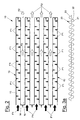
- the paper filter for particulate object of the present invention in particular a paper filter for particulate emitted together with the exhaust gases of internal combustion engines, is produced as a folded up sheet in the form of a "Greek key" with several filtrating layers placed substantially parallel, connected by means of folds, the layers being separated and maintained equidistant through the interposition of spacers comprising at least one corrugated paper sheet or pleated paper.
- a paper filter 10 with reference to the figures, is illustrated, suitable to filter the particulate emitted together with the exhaust gases of internal combustion engines, in particular Diesel cycle engines.
- Filter 10 comprises a filtering element 11 made of a suitable microporous paper folded in the form of a "Greek key", having several layers 13 placed substantially parallel, connected through folds 14 of the same filtering paper.
- microporous paper normally used for the air filters in the internal combustion engines in a particular embodiment, represents a very efficient filtering system for the exhaust gases of the Diesel cycle engines.
- microporous paper is available on the market, suitable to tolerate, without any problem, temperatures of about 150°C, temperature obtainable by cooling down, through simple means, the exhaust gas, when really necessary.
- the layers 13 are separated by interposing a spacer 20 consisting of corrugated or pleated paper having a stiffness so as to prevent the collapse of the layers 13.
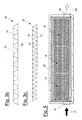
- this spacer 20 is made, for example, by means of corrugated board 21.
- a corrugated paper 21 is preferably used, stuck along the generatrix to a supporting paper sheet or cover 22, available in normal production, in order to confer higher resistance and to allow to automate the production of the filter; this set is hereinafter referred to as "corrugated paper with a cover”.
- This corrugated paper with a cover is placed, to make the spacer 20, as shown in figure 3a, with two sheets of corrugated paper with a cover joint together by sticking the covers 22 to form a spacer 20 having the wanted thickness and consistency, which presents corrugated surfaces both on its upper and lower side.
- the spacer 20 can be advantageously produced as described above, or as shown in figure 3c, by using pleated paper 23.
- this spacer 20 is to prevent the collapse of the layers 13, as the spacer 20, by working under compression, sustains the above-mentioned layers 13 of filtering paper, maintaining them substantially at the same distance, thus guaranteeing an uniform filtration.
- the essential condition for its functioning is, in fact, that the single layers 13 of the filtering element stay in their position, i.e. parallel and at the same distance.
- This spacer 20 in whatever form is made, is placed with the generatrix of waves, or the folds, parallel to the gas flow defined by the arrows F1 in figures 1a and 2.
- This disposition of layers 13 and spacers 20 defines an alternate series of "dirty" cells 15 in which the gas to be filtered circulates, which is sent to the filtering paper through ducts 25 delimited by the waves 21 or folds 23 and by the filtering layers 13.
- Said cells 15 of gas to be filtered shown by the arrows F1
- alternate, in the "Greek key” disposition of the filter with "clean” cells 16, in which the filtered gas, shown by the arrows F2, circulates.
- the gas is filtered when passes through these layers 13, according to the direction defined by arrows F'1, and, even if in a small portion, also through the front end of the filtering element 11, passing through the folds 14.
- Gas enters into the cells 16 of the filtered gas and is sent to atmosphere through ducts 26, in turn delimited by waves 21 or pleatings 23 and by adjacent layers 13.
- the side closing is shown , which is effected by folding the hedges 12 obtained thanks to the excess of the filtering microporous paper.
- the spacer is kept, in fact, about 15 mm shorter, on both sides, of the layers 13, the filtering paper is moisten, by means of a glue, along said hedges 12, which are then folded upwards or downwards so as to obtain a shingle lap.
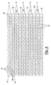
- Filter 10 as illustrated in figure 5, according to the preferred embodiment, is housed, singularly or in several replaceable elements, inside a container 30, easily mounted on a vehicle.
- Said container 30 has an inlet duct, 31 oriented according to the direction F1, of the gas to be filtered, to be connected to the engine exhaust, and an outlet duct 32, oriented towards the direction F2, of the filtered gas to be released to the atmosphere.
- a suitable by-pass can be positioned upstream the inlet duct 31, selected, for example, by means of an intercepting valve, automatic or controlled by the driver, or by positioning, at the filter inlet, a suitable condensate separator easily found on the market.
- the filter can also be equipped with a sensor which informs the driver that the filter must be shortly substituted.
- the filter according to the invention realizes the wanted objects, in particular:
Abstract
Description
- The present invention concerns a microporous paper filter for particulates.
- More in detail, the invention concerns a microporous paper filter for particulate, having large volume surface to filter the particulate released together with the exhaust gases of internal combustion engines, such as the Diesel cycle engines.
- The general problem of environmental pollution, produced not only by the internal combustion engines, in particular the Diesel cycle engines, but also through different sources, such as, for example, the burners of the heating systems, is mainly centered on the particulate comprising unburned carbon particles which, when of small particle size, normally smaller than 10 microns, represent a great danger for the health of the inhaling person.
- The atmospheric conditions, the traffic increase in cities and the increase of the Diesel cycle engines, have greatly increased the problem, and drastic measures for the traffic limitation were adopted in urban areas.
- Various solutions have been proposed to remedy a continuously worsening pollution situation, operating according to different principles.
- Among the filtering systems proposed, there are those called self-regenerating, for example a filter is well known, consisting of a device comprising a section containing a catalyst which generates nitrogen dioxide (NO2), followed by a section consisting of a ceramic filter capable of retaining the particulate.
- When this filter reaches the temperature of 250°C, NO2 triggers the combustion of the carbon particles trapped in the filter, thus preventing the progressive obstruction.
- But the above-described device has some limitations:
- gas oil must not contain sulfur, otherwise the catalyst is poisoned;
- the device functioning is linked to the exhaust gas temperature;
- the combustion ashes of the lubricating oil cannot be eliminated from the particulate filter, which, therefore, is progressively obstructed;
- the NO2 production can represent a danger for the environment;
- it is not easy to verify the efficacy of the system during the running of time.
- This solution did not have, for the above reasons, great success for the solution of the environmental pollution problem due to exhaust gases.
- The general object of the present invention is, therefore, to produce a microporous paper filter for particulate, having high volume surface, which results fairly durable.
- Another object of the present invention is to produce a microporous paper filter of particularly reduced dimensions, which can be housed into a container, of economical production and simple installation and substitution.
- Another object of the present invention is to produce a filter consisting of a microporous paper suitably selected, capable of retaining the particulate emitted together with the discharge gases of internal combustion engines, particularly Diesel cycle engines, having dimensions lower than 10 microns.
- Another object of the present invention is to produce a filter which allows not to disperse the particulate, separated from the exhaust gases, in the atmosphere.
- A further object of the present invention is to produce a filter which does not present an appreciable pressure drop for the gases which go through it, therefore which does not cause significant counter-pressures in the exhaust.
- These and other objects according to the present invention are reached by a microporous paper filter for particulate according to claim 1.
- Further characteristics of the invention form the subject of the dependent claims.
- The paper filter for particulate object of the present invention, in particular a paper filter for particulate emitted together with the exhaust gases of internal combustion engines, is produced as a folded up sheet in the form of a "Greek key" with several filtrating layers placed substantially parallel, connected by means of folds, the layers being separated and maintained equidistant through the interposition of spacers comprising at least one corrugated paper sheet or pleated paper.
- The characteristics and advantages of a microporous paper filter for particulate according to the present invention, will appear more evident from the following description, illustrative but not limiting, referred to the enclosed schematic drawings, wherein:
- figures 1a and 1b are prospect views of the filter according to the invention;
- figure 2 is a side schematic view of a particular of the filter according to the invention;
- figures 3a-3c are detail views of the filter according to the invention;
- figure 4 is a schematic front view of the filter of figure 1a;
- figure 5 is a schematic front view of the filter of figure 4 housed into a container.
-
- A
paper filter 10, with reference to the figures, is illustrated, suitable to filter the particulate emitted together with the exhaust gases of internal combustion engines, in particular Diesel cycle engines. -
Filter 10, according to the invention, comprises a filteringelement 11 made of a suitable microporous paper folded in the form of a "Greek key", havingseveral layers 13 placed substantially parallel, connected throughfolds 14 of the same filtering paper. - On the basis of researches and experimentations, the Applicant reached the conclusion that the microporous paper normally used for the air filters in the internal combustion engines, in a particular embodiment, represents a very efficient filtering system for the exhaust gases of the Diesel cycle engines.
- Moreover, when papers with filtering efficiency higher than 99% for particles around 1 micron, and a specific area expressed as a suitable function of the engine power (m2/Kw) are used, it can be noted that the filter can treat very high volumes of gas, before showing remarkable pressure drops.
- This is due to the filtering power of the particulate collected on the paper, which, in turn, acts as a filter, preventing the finest particles to obstruct the paper micropores.
- Contrary to a prejudice strongly accepted and amply mentioned in literature, the Applicant observed that microporous paper is available on the market, suitable to tolerate, without any problem, temperatures of about 150°C, temperature obtainable by cooling down, through simple means, the exhaust gas, when really necessary.
- The
layers 13 are separated by interposing aspacer 20 consisting of corrugated or pleated paper having a stiffness so as to prevent the collapse of thelayers 13. - In this way, a large surface of filtering paper is available in a limited space, thus producing a filter having high volume surface.
- With particular reference to figure 3b, this
spacer 20 is made, for example, by means ofcorrugated board 21. - A
corrugated paper 21 is preferably used, stuck along the generatrix to a supporting paper sheet orcover 22, available in normal production, in order to confer higher resistance and to allow to automate the production of the filter; this set is hereinafter referred to as "corrugated paper with a cover". - This corrugated paper with a cover is placed, to make the
spacer 20, as shown in figure 3a, with two sheets of corrugated paper with a cover joint together by sticking thecovers 22 to form aspacer 20 having the wanted thickness and consistency, which presents corrugated surfaces both on its upper and lower side. - The
spacer 20 can be advantageously produced as described above, or as shown in figure 3c, by using pleatedpaper 23. - The purpose of this
spacer 20 is to prevent the collapse of thelayers 13, as thespacer 20, by working under compression, sustains the above-mentionedlayers 13 of filtering paper, maintaining them substantially at the same distance, thus guaranteeing an uniform filtration. - The essential condition for its functioning is, in fact, that the
single layers 13 of the filtering element stay in their position, i.e. parallel and at the same distance. - In the absence of
spacers 20, at the increase of the filter obstruction, therefore of the pressure drop that the gas suffers when it goes through, thelayers 13, among which the filtered gas circulates, would tend to get closer and, when they come into contact, the filter would clog and would stop functioning. - This
spacer 20, in whatever form is made, is placed with the generatrix of waves, or the folds, parallel to the gas flow defined by the arrows F1 in figures 1a and 2. - This disposition of
layers 13 andspacers 20 defines an alternate series of "dirty"cells 15 in which the gas to be filtered circulates, which is sent to the filtering paper throughducts 25 delimited by thewaves 21 orfolds 23 and by the filteringlayers 13. - Said
cells 15 of gas to be filtered, shown by the arrows F1, alternate, in the "Greek key" disposition of the filter, with "clean"cells 16, in which the filtered gas, shown by the arrows F2, circulates. - The gas is filtered when passes through these
layers 13, according to the direction defined by arrows F'1, and, even if in a small portion, also through the front end of thefiltering element 11, passing through thefolds 14. - Gas enters into the
cells 16 of the filtered gas and is sent to atmosphere throughducts 26, in turn delimited bywaves 21 orpleatings 23 and byadjacent layers 13. - With particular reference to figure 1b, the side closing is shown , which is effected by folding the
hedges 12 obtained thanks to the excess of the filtering microporous paper. - The spacer is kept, in fact, about 15 mm shorter, on both sides, of the
layers 13, the filtering paper is moisten, by means of a glue, along saidhedges 12, which are then folded upwards or downwards so as to obtain a shingle lap. - In this way, there is no communication between the cells through which the gas to be filtered flows, which have higher pressure, and those through which the filtered gas flows, at lower pressure.
-
Filter 10, as illustrated in figure 5, according to the preferred embodiment, is housed, singularly or in several replaceable elements, inside acontainer 30, easily mounted on a vehicle. - Said
container 30 has an inlet duct, 31 oriented according to the direction F1, of the gas to be filtered, to be connected to the engine exhaust, and anoutlet duct 32, oriented towards the direction F2, of the filtered gas to be released to the atmosphere. - Particular care must be taken for the condensate - which is formed at the start up, particularly during winter time - not to reach the filtrating paper; for this purpose, a suitable by-pass can be positioned upstream the
inlet duct 31, selected, for example, by means of an intercepting valve, automatic or controlled by the driver, or by positioning, at the filter inlet, a suitable condensate separator easily found on the market. - The filter can also be equipped with a sensor which informs the driver that the filter must be shortly substituted.
- The filter according to the invention realizes the wanted objects, in particular:
- paper based filter, of very reduced dimensions but which can be used for quite long time before being substituted;
- the filter causes extremely limited counter-pressures to the engine exhaust;
- dimensions suitable to allow use both on commercial vehicles and cars;
- substitution interval can be prolonged thanks to the possibility of excluding the filter under particular conditions, for example when the vehicle runs on extra-urban areas;
- possibility of disposing of the used filter and its content of particulate without problems, for example by incineration, thanks to the use of materials mainly based on cellulose;
- reduced costs, both of the replaceable filtering device and the container to be placed on the vehicle.
Claims (6)
- A paper filter for filtering particulates emitted together with the exhaust gases of internal combustion engines, characterized in that comprises a filtering element (11) made in the form of a folded up sheet to form a "Greek key", having several filtering layers (13) placed substantially parallel, connected by means of folds (14), said layers (13) being separated and maintained equidistant through the interposition of spacers (20) of such a rigidity as to prevent the collapse of the layers (13).
- The microporous paper filter according to claim 1, wherein said spacers (20) comprises each at least a corrugated paper sheet placed with the generatrix of the waves parallel to the direction of the inlet gas flow (F1) in the filtering element (11).
- The filter according claim 1 or 2, wherein said spacer (20) consists of at least one couple of corrugated board, each with a cover consisting of corrugated board (21) stuck along the generatrix to a cover (22) in the form of a plane sheet, said sheets of corrugated boards with a cover being glued, back to back, by means of the covers.
- The filter according to claim 1, wherein said spacer (20) comprises pleated paper (23) placed with the generatrix of the folds parallel to the direction (F1) of the inlet gas flow of the filtering element (11).
- The filter according to claim 1, wherein said filtering element (11) presents, at the sides, foldable hedges (12) which can be glued so as to obtain a shingle lap for the side closing of the filter.
- The filter according to claim 1, wherein said filter (10) is conceived for being housed, singularly or in several elements, into a container (30) suitable for being assembled on a vehicle.
Applications Claiming Priority (2)
| Application Number | Priority Date | Filing Date | Title |
|---|---|---|---|
| IT000960A ITMI20030960A1 (en) | 2003-05-13 | 2003-05-13 | MICROPOROUS PAPER FILTER FOR PARTICULATE. |
| ITMI20030960 | 2003-05-13 |
Publications (2)
| Publication Number | Publication Date |
|---|---|
| EP1477217A1 true EP1477217A1 (en) | 2004-11-17 |
| EP1477217B1 EP1477217B1 (en) | 2008-07-09 |
Family
ID=33017976
Family Applications (1)
| Application Number | Title | Priority Date | Filing Date |
|---|---|---|---|
| EP04076412A Not-in-force EP1477217B1 (en) | 2003-05-13 | 2004-05-12 | Microporous paper filter for particulates |
Country Status (6)
| Country | Link |
|---|---|
| US (1) | US7217309B2 (en) |
| EP (1) | EP1477217B1 (en) |
| AT (1) | ATE400347T1 (en) |
| CA (1) | CA2467007A1 (en) |
| DE (1) | DE602004014841D1 (en) |
| IT (1) | ITMI20030960A1 (en) |
Cited By (1)
| Publication number | Priority date | Publication date | Assignee | Title |
|---|---|---|---|---|
| IT201800000622A1 (en) * | 2018-01-08 | 2019-07-08 | Nextmaterials S R L | Cardboard filters for the abatement of pollutants |
Families Citing this family (11)
| Publication number | Priority date | Publication date | Assignee | Title |
|---|---|---|---|---|
| DE10356997A1 (en) * | 2003-12-03 | 2005-07-07 | Helmut Swars | particulate Filter |
| SE527578C2 (en) * | 2004-05-26 | 2006-04-11 | Absolent Ab | Filter cartridge consisting of a housing surrounding a pleated filter mat with spacers between parallel opposite filter mat parts |
| WO2007054952A2 (en) * | 2005-11-09 | 2007-05-18 | Hamish Chandru Shahani | Pleated filter with isokinetic spacers |
| US7588619B2 (en) * | 2006-11-28 | 2009-09-15 | Wix Filtration Corp. | Cross-flow filter media and filter assembly |
| CA2747798C (en) | 2008-01-14 | 2016-07-12 | Dpoint Technologies Inc. | Cross-pleated membrane cartridges, and method and apparatus for making cross-pleated membrane cartridges |
| CN101532412B (en) * | 2008-03-10 | 2011-07-06 | 王凯 | Automobile exhaust purification method and automobile exhaust purification system thereof |
| US20100300082A1 (en) * | 2009-05-26 | 2010-12-02 | Xiaogang Zhang | Diesel particulate filter |
| FR2949811B1 (en) | 2009-09-04 | 2018-07-13 | Renault S.A.S. | FILTER DEVICE FOR INTERNAL COMBUSTION ENGINE |
| DE102011050915A1 (en) * | 2011-06-08 | 2012-12-13 | Neufilter Gmbh | A paper jelly filter module, method for making such a paper jelly filter module and paper jelly filter module wall from a plurality of such paper jelly filter modules |
| IT201600130256A1 (en) * | 2016-12-22 | 2018-06-22 | Wamgroup Spa | DUST REMOVER FOR GASEOUS FLUIDS AND METHOD OF REALIZING IT |
| JP7363256B2 (en) * | 2019-09-18 | 2023-10-18 | 富士フイルムビジネスイノベーション株式会社 | Filters, collectors and image forming devices |
Citations (3)
| Publication number | Priority date | Publication date | Assignee | Title |
|---|---|---|---|---|
| EP0457018A1 (en) * | 1990-05-18 | 1991-11-21 | REFIL Gmbh Filtertechnik + Recycling | Disposition of filter elements and separating supports as a package in a filter housing |
| JPH05115734A (en) * | 1991-10-24 | 1993-05-14 | Nippondenso Co Ltd | Air filter |
| JPH06299840A (en) * | 1993-04-13 | 1994-10-25 | Isuzu Ceramics Kenkyusho:Kk | Diesel particulate filter |
Family Cites Families (16)
| Publication number | Priority date | Publication date | Assignee | Title |
|---|---|---|---|---|
| US2019186A (en) * | 1933-03-01 | 1935-10-29 | H S Kaiser Company | Air filter |
| US2884091A (en) * | 1957-05-06 | 1959-04-28 | Cambridge Filter Mfg Corp | Filters |
| US3941571A (en) * | 1975-04-07 | 1976-03-02 | American Air Filter Company, Inc. | Filter pleat fold spacer |
| US4725411A (en) * | 1985-11-12 | 1988-02-16 | W. R. Grace & Co. | Device for physical and/or chemical treatment of fluids |
| DE3622629A1 (en) * | 1986-07-05 | 1988-01-07 | Kernforschungsz Karlsruhe | Filter pack |
| US4942020A (en) * | 1988-06-27 | 1990-07-17 | W.R. Grace & Co.-Conn. | Converter for removing pollutants from a gas stream |
| JP3362453B2 (en) * | 1993-05-21 | 2003-01-07 | 株式会社デンソー | Filtration element |
| FR2741279B1 (en) * | 1995-11-17 | 2001-06-15 | Inst Francais Du Petrole | HIGH ADSORPTION PACKING BLOCK FOR GAS EFFLUENT PURIFICATION DEVICE |
| JP3434117B2 (en) * | 1996-03-29 | 2003-08-04 | 住友電気工業株式会社 | Particulate trap for diesel engine |
| US6524488B1 (en) * | 1998-06-18 | 2003-02-25 | 3M Innovative Properties Company | Method of filtering certain particles from a fluid using a depth loading filtration media |
| GB9805224D0 (en) * | 1998-03-12 | 1998-05-06 | Philips Electronics Nv | Air filters |
| US6280824B1 (en) * | 1999-01-29 | 2001-08-28 | 3M Innovative Properties Company | Contoured layer channel flow filtration media |
| US6273938B1 (en) * | 1999-08-13 | 2001-08-14 | 3M Innovative Properties Company | Channel flow filter |
| US6585793B2 (en) * | 2000-12-29 | 2003-07-01 | Andreae Filters, Inc. | Filter apparatus and methods |
| US20020088314A1 (en) * | 2001-01-11 | 2002-07-11 | Myron Wambem | Radius wrench handle |
| US6942708B2 (en) * | 2002-04-18 | 2005-09-13 | Rypos, Inc. | Bifilar diesel exhaust filter construction using sintered metal fibers |
-
2003
- 2003-05-13 IT IT000960A patent/ITMI20030960A1/en unknown
-
2004
- 2004-05-10 US US10/842,096 patent/US7217309B2/en not_active Expired - Fee Related
- 2004-05-12 CA CA002467007A patent/CA2467007A1/en not_active Abandoned
- 2004-05-12 EP EP04076412A patent/EP1477217B1/en not_active Not-in-force
- 2004-05-12 DE DE602004014841T patent/DE602004014841D1/en not_active Expired - Fee Related
- 2004-05-12 AT AT04076412T patent/ATE400347T1/en not_active IP Right Cessation
Patent Citations (3)
| Publication number | Priority date | Publication date | Assignee | Title |
|---|---|---|---|---|
| EP0457018A1 (en) * | 1990-05-18 | 1991-11-21 | REFIL Gmbh Filtertechnik + Recycling | Disposition of filter elements and separating supports as a package in a filter housing |
| JPH05115734A (en) * | 1991-10-24 | 1993-05-14 | Nippondenso Co Ltd | Air filter |
| JPH06299840A (en) * | 1993-04-13 | 1994-10-25 | Isuzu Ceramics Kenkyusho:Kk | Diesel particulate filter |
Non-Patent Citations (2)
| Title |
|---|
| PATENT ABSTRACTS OF JAPAN vol. 017, no. 475 30 August 1993 (1993-08-30) * |
| PATENT ABSTRACTS OF JAPAN vol. 1995, no. 01 28 February 1995 (1995-02-28) * |
Cited By (1)
| Publication number | Priority date | Publication date | Assignee | Title |
|---|---|---|---|---|
| IT201800000622A1 (en) * | 2018-01-08 | 2019-07-08 | Nextmaterials S R L | Cardboard filters for the abatement of pollutants |
Also Published As
| Publication number | Publication date |
|---|---|
| DE602004014841D1 (en) | 2008-08-21 |
| US7217309B2 (en) | 2007-05-15 |
| EP1477217B1 (en) | 2008-07-09 |
| ITMI20030960A1 (en) | 2004-11-14 |
| CA2467007A1 (en) | 2004-11-13 |
| ATE400347T1 (en) | 2008-07-15 |
| US20040226274A1 (en) | 2004-11-18 |
Similar Documents
| Publication | Publication Date | Title |
|---|---|---|
| EP1477217B1 (en) | Microporous paper filter for particulates | |
| US3633343A (en) | Automotive exhaust filter | |
| EP0264202B1 (en) | Low energy regeneration system for particulate trap for an internal combustion engine | |
| US20040139734A1 (en) | Apparatus for emissions control, system, and methods | |
| US7682578B2 (en) | Device for catalytically reducing exhaust | |
| US6024927A (en) | Particulate trap | |
| JP2018501101A (en) | filter | |
| US7640732B2 (en) | Method and apparatus for filtration of a two-stroke engine exhaust | |
| US20070107396A1 (en) | Method and apparatus for a gas-liquid separator | |
| US20020141910A1 (en) | Regenerable diesel exhaust filter | |
| WO2013158007A1 (en) | Device and method for elimination of particles from gaseous media | |
| KR101174113B1 (en) | Metal foam filter for diesel particulate filter trap | |
| US7682577B2 (en) | Catalytic exhaust device for simplified installation or replacement | |
| US7451849B1 (en) | Substantially fibrous exhaust screening system for motor vehicles | |
| EP1531241B1 (en) | Filtering device at a controlled temperature | |
| WO2001033050A1 (en) | Filter | |
| EP1643090B1 (en) | Controlled bypass of a filtration device | |
| US20080295467A1 (en) | Particulate Filter for an Internal Combustion Engine | |
| JP2003214142A (en) | Diesel particulate removing device and diesel vehicle provided with the same | |
| JPS5999019A (en) | Exhaust-gas purifying apparatus for diesel engine | |
| CN2309177Y (en) | Air cleaner | |
| CN215170268U (en) | Wall type streaming filter module, filter material and oil-gas separator | |
| JP2002276342A (en) | Device for removing particulate | |
| US20240082765A1 (en) | Particulate filter | |
| JPS6311292Y2 (en) |
Legal Events
| Date | Code | Title | Description |
|---|---|---|---|
| PUAI | Public reference made under article 153(3) epc to a published international application that has entered the european phase |
Free format text: ORIGINAL CODE: 0009012 |
|
| AK | Designated contracting states |
Kind code of ref document: A1 Designated state(s): AT BE BG CH CY CZ DE DK EE ES FI FR GB GR HU IE IT LI LU MC NL PL PT RO SE SI SK TR |
|
| AX | Request for extension of the european patent |
Extension state: AL HR LT LV MK |
|
| 17P | Request for examination filed |
Effective date: 20050223 |
|
| AKX | Designation fees paid |
Designated state(s): AT BE BG CH CY CZ DE DK EE ES FI FR GB GR HU IE IT LI LU MC NL PL PT RO SE SI SK TR |
|
| REG | Reference to a national code |
Ref country code: HK Ref legal event code: DE Ref document number: 1073446 Country of ref document: HK |
|
| 17Q | First examination report despatched |
Effective date: 20070110 |
|
| GRAP | Despatch of communication of intention to grant a patent |
Free format text: ORIGINAL CODE: EPIDOSNIGR1 |
|
| GRAS | Grant fee paid |
Free format text: ORIGINAL CODE: EPIDOSNIGR3 |
|
| GRAA | (expected) grant |
Free format text: ORIGINAL CODE: 0009210 |
|
| AK | Designated contracting states |
Kind code of ref document: B1 Designated state(s): AT BE BG CH CY CZ DE DK EE ES FI FR GB GR HU IE IT LI LU MC NL PL PT RO SE SI SK TR |
|
| REG | Reference to a national code |
Ref country code: GB Ref legal event code: FG4D |
|
| REG | Reference to a national code |
Ref country code: CH Ref legal event code: EP |
|
| REF | Corresponds to: |
Ref document number: 602004014841 Country of ref document: DE Date of ref document: 20080821 Kind code of ref document: P |
|
| REG | Reference to a national code |
Ref country code: IE Ref legal event code: FG4D |
|
| NLV1 | Nl: lapsed or annulled due to failure to fulfill the requirements of art. 29p and 29m of the patents act | ||
| PG25 | Lapsed in a contracting state [announced via postgrant information from national office to epo] |
Ref country code: NL Free format text: LAPSE BECAUSE OF FAILURE TO SUBMIT A TRANSLATION OF THE DESCRIPTION OR TO PAY THE FEE WITHIN THE PRESCRIBED TIME-LIMIT Effective date: 20080709 Ref country code: PT Free format text: LAPSE BECAUSE OF FAILURE TO SUBMIT A TRANSLATION OF THE DESCRIPTION OR TO PAY THE FEE WITHIN THE PRESCRIBED TIME-LIMIT Effective date: 20081209 Ref country code: ES Free format text: LAPSE BECAUSE OF FAILURE TO SUBMIT A TRANSLATION OF THE DESCRIPTION OR TO PAY THE FEE WITHIN THE PRESCRIBED TIME-LIMIT Effective date: 20081020 |
|
| PG25 | Lapsed in a contracting state [announced via postgrant information from national office to epo] |
Ref country code: AT Free format text: LAPSE BECAUSE OF FAILURE TO SUBMIT A TRANSLATION OF THE DESCRIPTION OR TO PAY THE FEE WITHIN THE PRESCRIBED TIME-LIMIT Effective date: 20080709 Ref country code: SI Free format text: LAPSE BECAUSE OF FAILURE TO SUBMIT A TRANSLATION OF THE DESCRIPTION OR TO PAY THE FEE WITHIN THE PRESCRIBED TIME-LIMIT Effective date: 20080709 Ref country code: BG Free format text: LAPSE BECAUSE OF FAILURE TO SUBMIT A TRANSLATION OF THE DESCRIPTION OR TO PAY THE FEE WITHIN THE PRESCRIBED TIME-LIMIT Effective date: 20081009 Ref country code: FI Free format text: LAPSE BECAUSE OF FAILURE TO SUBMIT A TRANSLATION OF THE DESCRIPTION OR TO PAY THE FEE WITHIN THE PRESCRIBED TIME-LIMIT Effective date: 20080709 |
|
| PG25 | Lapsed in a contracting state [announced via postgrant information from national office to epo] |
Ref country code: BE Free format text: LAPSE BECAUSE OF FAILURE TO SUBMIT A TRANSLATION OF THE DESCRIPTION OR TO PAY THE FEE WITHIN THE PRESCRIBED TIME-LIMIT Effective date: 20080709 |
|
| PG25 | Lapsed in a contracting state [announced via postgrant information from national office to epo] |
Ref country code: EE Free format text: LAPSE BECAUSE OF FAILURE TO SUBMIT A TRANSLATION OF THE DESCRIPTION OR TO PAY THE FEE WITHIN THE PRESCRIBED TIME-LIMIT Effective date: 20080709 Ref country code: DK Free format text: LAPSE BECAUSE OF FAILURE TO SUBMIT A TRANSLATION OF THE DESCRIPTION OR TO PAY THE FEE WITHIN THE PRESCRIBED TIME-LIMIT Effective date: 20080709 |
|
| PLBE | No opposition filed within time limit |
Free format text: ORIGINAL CODE: 0009261 |
|
| STAA | Information on the status of an ep patent application or granted ep patent |
Free format text: STATUS: NO OPPOSITION FILED WITHIN TIME LIMIT |
|
| PG25 | Lapsed in a contracting state [announced via postgrant information from national office to epo] |
Ref country code: CZ Free format text: LAPSE BECAUSE OF FAILURE TO SUBMIT A TRANSLATION OF THE DESCRIPTION OR TO PAY THE FEE WITHIN THE PRESCRIBED TIME-LIMIT Effective date: 20080709 Ref country code: SK Free format text: LAPSE BECAUSE OF FAILURE TO SUBMIT A TRANSLATION OF THE DESCRIPTION OR TO PAY THE FEE WITHIN THE PRESCRIBED TIME-LIMIT Effective date: 20080709 Ref country code: RO Free format text: LAPSE BECAUSE OF FAILURE TO SUBMIT A TRANSLATION OF THE DESCRIPTION OR TO PAY THE FEE WITHIN THE PRESCRIBED TIME-LIMIT Effective date: 20080709 |
|
| 26N | No opposition filed |
Effective date: 20090414 |
|
| PG25 | Lapsed in a contracting state [announced via postgrant information from national office to epo] |
Ref country code: MC Free format text: LAPSE BECAUSE OF NON-PAYMENT OF DUE FEES Effective date: 20090531 |
|
| REG | Reference to a national code |
Ref country code: CH Ref legal event code: PL |
|
| GBPC | Gb: european patent ceased through non-payment of renewal fee |
Effective date: 20090512 |
|
| PG25 | Lapsed in a contracting state [announced via postgrant information from national office to epo] |
Ref country code: CH Free format text: LAPSE BECAUSE OF NON-PAYMENT OF DUE FEES Effective date: 20090531 Ref country code: SE Free format text: LAPSE BECAUSE OF FAILURE TO SUBMIT A TRANSLATION OF THE DESCRIPTION OR TO PAY THE FEE WITHIN THE PRESCRIBED TIME-LIMIT Effective date: 20081009 Ref country code: LI Free format text: LAPSE BECAUSE OF NON-PAYMENT OF DUE FEES Effective date: 20090531 |
|
| REG | Reference to a national code |
Ref country code: FR Ref legal event code: ST Effective date: 20100129 |
|
| PG25 | Lapsed in a contracting state [announced via postgrant information from national office to epo] |
Ref country code: IE Free format text: LAPSE BECAUSE OF NON-PAYMENT OF DUE FEES Effective date: 20090512 Ref country code: FR Free format text: LAPSE BECAUSE OF NON-PAYMENT OF DUE FEES Effective date: 20090602 |
|
| PG25 | Lapsed in a contracting state [announced via postgrant information from national office to epo] |
Ref country code: PL Free format text: LAPSE BECAUSE OF FAILURE TO SUBMIT A TRANSLATION OF THE DESCRIPTION OR TO PAY THE FEE WITHIN THE PRESCRIBED TIME-LIMIT Effective date: 20080709 Ref country code: GB Free format text: LAPSE BECAUSE OF NON-PAYMENT OF DUE FEES Effective date: 20090512 |
|
| PG25 | Lapsed in a contracting state [announced via postgrant information from national office to epo] |
Ref country code: DE Free format text: LAPSE BECAUSE OF NON-PAYMENT OF DUE FEES Effective date: 20091201 |
|
| PG25 | Lapsed in a contracting state [announced via postgrant information from national office to epo] |
Ref country code: GR Free format text: LAPSE BECAUSE OF FAILURE TO SUBMIT A TRANSLATION OF THE DESCRIPTION OR TO PAY THE FEE WITHIN THE PRESCRIBED TIME-LIMIT Effective date: 20081010 |
|
| PG25 | Lapsed in a contracting state [announced via postgrant information from national office to epo] |
Ref country code: IT Free format text: LAPSE BECAUSE OF NON-PAYMENT OF DUE FEES Effective date: 20100512 |
|
| PG25 | Lapsed in a contracting state [announced via postgrant information from national office to epo] |
Ref country code: LU Free format text: LAPSE BECAUSE OF NON-PAYMENT OF DUE FEES Effective date: 20090512 |
|
| PG25 | Lapsed in a contracting state [announced via postgrant information from national office to epo] |
Ref country code: HU Free format text: LAPSE BECAUSE OF FAILURE TO SUBMIT A TRANSLATION OF THE DESCRIPTION OR TO PAY THE FEE WITHIN THE PRESCRIBED TIME-LIMIT Effective date: 20090110 |
|
| PGRI | Patent reinstated in contracting state [announced from national office to epo] |
Ref country code: IT Effective date: 20110616 |
|
| PG25 | Lapsed in a contracting state [announced via postgrant information from national office to epo] |
Ref country code: TR Free format text: LAPSE BECAUSE OF FAILURE TO SUBMIT A TRANSLATION OF THE DESCRIPTION OR TO PAY THE FEE WITHIN THE PRESCRIBED TIME-LIMIT Effective date: 20080709 |
|
| PG25 | Lapsed in a contracting state [announced via postgrant information from national office to epo] |
Ref country code: CY Free format text: LAPSE BECAUSE OF FAILURE TO SUBMIT A TRANSLATION OF THE DESCRIPTION OR TO PAY THE FEE WITHIN THE PRESCRIBED TIME-LIMIT Effective date: 20080709 |
|
| REG | Reference to a national code |
Ref country code: HK Ref legal event code: WD Ref document number: 1073446 Country of ref document: HK |
|
| PGFP | Annual fee paid to national office [announced via postgrant information from national office to epo] |
Ref country code: IT Payment date: 20140422 Year of fee payment: 11 |
|
| PG25 | Lapsed in a contracting state [announced via postgrant information from national office to epo] |
Ref country code: IT Free format text: LAPSE BECAUSE OF NON-PAYMENT OF DUE FEES Effective date: 20150512 |