EP1477091A1 - Water supply tank unit and heating apparatus having the same - Google Patents
Water supply tank unit and heating apparatus having the same Download PDFInfo
- Publication number
- EP1477091A1 EP1477091A1 EP04011571A EP04011571A EP1477091A1 EP 1477091 A1 EP1477091 A1 EP 1477091A1 EP 04011571 A EP04011571 A EP 04011571A EP 04011571 A EP04011571 A EP 04011571A EP 1477091 A1 EP1477091 A1 EP 1477091A1
- Authority
- EP
- European Patent Office
- Prior art keywords
- water supply
- tank
- supply tank
- water
- support member
- Prior art date
- Legal status (The legal status is an assumption and is not a legal conclusion. Google has not performed a legal analysis and makes no representation as to the accuracy of the status listed.)
- Granted
Links
Images




Classifications
-
- H—ELECTRICITY
- H05—ELECTRIC TECHNIQUES NOT OTHERWISE PROVIDED FOR
- H05B—ELECTRIC HEATING; ELECTRIC LIGHT SOURCES NOT OTHERWISE PROVIDED FOR; CIRCUIT ARRANGEMENTS FOR ELECTRIC LIGHT SOURCES, IN GENERAL
- H05B6/00—Heating by electric, magnetic or electromagnetic fields
- H05B6/64—Heating using microwaves
- H05B6/647—Aspects related to microwave heating combined with other heating techniques
- H05B6/6473—Aspects related to microwave heating combined with other heating techniques combined with convection heating
- H05B6/6479—Aspects related to microwave heating combined with other heating techniques combined with convection heating using steam
-
- H—ELECTRICITY
- H05—ELECTRIC TECHNIQUES NOT OTHERWISE PROVIDED FOR
- H05B—ELECTRIC HEATING; ELECTRIC LIGHT SOURCES NOT OTHERWISE PROVIDED FOR; CIRCUIT ARRANGEMENTS FOR ELECTRIC LIGHT SOURCES, IN GENERAL
- H05B6/00—Heating by electric, magnetic or electromagnetic fields
- H05B6/64—Heating using microwaves
- H05B6/6426—Aspects relating to the exterior of the microwave heating apparatus, e.g. metal casing, power cord
-
- A—HUMAN NECESSITIES
- A47—FURNITURE; DOMESTIC ARTICLES OR APPLIANCES; COFFEE MILLS; SPICE MILLS; SUCTION CLEANERS IN GENERAL
- A47J—KITCHEN EQUIPMENT; COFFEE MILLS; SPICE MILLS; APPARATUS FOR MAKING BEVERAGES
- A47J27/00—Cooking-vessels
- A47J27/04—Cooking-vessels for cooking food in steam; Devices for extracting fruit juice by means of steam ; Vacuum cooking vessels
-
- Y—GENERAL TAGGING OF NEW TECHNOLOGICAL DEVELOPMENTS; GENERAL TAGGING OF CROSS-SECTIONAL TECHNOLOGIES SPANNING OVER SEVERAL SECTIONS OF THE IPC; TECHNICAL SUBJECTS COVERED BY FORMER USPC CROSS-REFERENCE ART COLLECTIONS [XRACs] AND DIGESTS
- Y10—TECHNICAL SUBJECTS COVERED BY FORMER USPC
- Y10S—TECHNICAL SUBJECTS COVERED BY FORMER USPC CROSS-REFERENCE ART COLLECTIONS [XRACs] AND DIGESTS
- Y10S261/00—Gas and liquid contact apparatus
- Y10S261/65—Vaporizers
Definitions
- the present invention relates to a water supply tank unit which is attached to a heating apparatus having a steam generating function and holds a water supply tank detachably. Moreover, the present invention relates to a heating apparatus having the water supply tank unit.
- a high-frequency heating apparatus provided with a high-frequency generating means which outputs a high frequency wave into a heating room in which a heated matter is housed, since it can efficiently heat the heated matter into the heating room in a short time, has spread rapidly as an electronic oven that is a heat cooking device for food material.
- the steam supply mechanism of the high-frequency heating apparatus with a steam generating function comprises a water supply tank installed in an apparatus body through an tank support member detachably; a supplied water receiver provided into a heating room; and a heating means which heats this supplied water receiver and evaporates the water on the supplied water receiver.
- the water is, after a water supply port provided for the water supply tank has been inserted into a water inlet on the heating apparatus side, is supplied through a water supply pipe connected to this water inlet to the water receiver.
- a small amount of water may drop into the water inlet due to pressure of the water supply pipe path.
- a water supply tank unit which is attached to a heating apparatus having a steam generating function and holds a water supply tank detachably, is characterized by comprising: a tank support member which has a water pour connection port connected to a water supply connection port with an inserting operation of the water supply tank, and a scupper provided at the bottom near the water pour connection port, and supports the inserted water supply tank; and a water absorption means provided below the scupper of the tank support member.
- the water that has leaked from the water supply connection port or the water pour connection port comes out through the scupper from the tank support member, and is absorbed by the water absorption means. Consequently, in case that the water has leaked out into the tank support member, the leaking water can be treated so as not to remain. In result, it is not misunderstood that the water is leaking from the water supply tank.
- the water supply tank unit of the invention is characterized in that at the bottom of the tank support member, a water-storing wall which surrounds the scupper and stands from the bottom is provided. Therefore, since the flow of the water that has leaked into the tank support member is stanched by the water storing wall, the water can be treated so as not to flow to the other area at the tank support member bottom than the area surrounded by the water storing wall.
- the water supply tank unit of the invention is characterized in that the water storing wall has at its part a straight wall part parallel to the inserting direction of the water supply tank, and the water supply tank has at the tank bottom a guide which comes into slide-contact with the straight wall part in insertion into the tank support member. Therefore, since the guide located at the water supply tank bottom can be brought into slide-contact with the straight wall part of the tank support member to insert the water supply tank into the tank support member, the water supply tank is held in an exact position.
- the water supply tank unit of the invention is characterized in that a raised bottom part which defines space for bringing the water storing wall of the tank support member and the bottom inside the water storing wall into no-contact with the tank bottom of the water supply tank when the water supply tank is held by the tank support member is formed at a part of the bottom of the water supply tank. Therefore, even in case that the water is attached onto the water storing wall or the bottom inside the water storing wall, this water is not attached onto the tank bottom, so that it is possible to prevent the water from leaking through the tank bottom to the outside of the water storing wall.
- the water supply tank unit of the invention is characterized in that: the tank support member has at its bottom an elastic fitting piece provided with a projection part which fits to the water supply tank inserted to the tank support member and locks the water supply tank; and the elastic fitting piece is formed by providing a cavity around the elastic fitting piece except its base part at the bottom of the tank support member, and the cavity is used as the scupper. Therefore, the water supply tank is held surely in the tank support member by the projection part. Further, since the water that has leaked into the tank support member drops from the cavity around the elastic fitting piece and is absorbed by the water absorption member, labor and cost for forming the scupper newly can be omitted.
- a reference numeral 100 refers to a high-frequency heating apparatus; 17 to a water supply tank; 20 to a water supply tank unit; 7 to a steam generating part; 25 to an evaporation tray; 1 to a sponge; 35 to an operation member; 27 to a tank case body; 25 to a side surface heat insulating plate; 51 to a tank body; 57 to a tank lid member; 55 to a water supply port; 54 to a raised bottom part; 54a, 69 to a projection; 52a, 52b to a bottom rib; 59 to a water inlet; 61 to a stanch rib; 65 to an upper surface part; 65a, 67a to a guide wall; 60 to a scupper; 63 to an elastic fitting piece; 61a, 61b to a straight wall part; 66 to an end part; 67 to a bottom surface part; 68 to a side surface part; 31a, 31b to a sidewall; 51a, 51b to a
- a reference sign S refers to a housing space.
- a heating apparatus having a steam generating function and being provided with a water supply tank unit
- a high-frequency heating apparatus with a steam generating function is taken.
- Fig. 1 is an exterior perspective view of a high-frequency heating apparatus with a steam generating function according to the invention
- Fig. 2 is a schematically front view showing a state where an opening-and-closing door of the high-frequency heating apparatus with a steam generating function is opened.
- a water supply tank unit in which a water supply tank for supplying water to a steam generating part is housed is arranged on a side surface of the high-frequency heating apparatus 100.
- the invention is characterized in that water leakage from this water supply tank unit, which is produced when the water supply tank unit is pulled out, does not have an influence on the high-frequency heating apparatus 100 side.
- This high-frequency heating apparatus 100 is a heat-cooking apparatus which supplies at least either a high-frequency wave (microwave) or steam to a heating room 3 in which a heated matter such as food material is housed to treat the heated matter by use of heat.
- the high-frequency heating apparatus 100 includes a magnetron 5 which outputs the high-frequency wave into the heating room 3 for housing the heated matter such as the food material therein, a steam generating part 7 which generates steam into the heating room 3, and a water supply tank 17 which is connected to a water supply passage to the steam generating part 7 detachably.
- the heating room 3 is formed inside a box-shaped body case 10 of which a front surface is open, and an opening-and-closing door 13 which has a light-permeable window 13a, and opens and closes a heated matter outlet is provided on the front surface of the body case 10.
- the magnetron 5 is arranged in space on the downside of the heating room 3, and a stirrer vane 47 is provided in a position where the high-frequency wave generated from this magnetron 5 is received.
- the high-frequency wave from the magnetron 5 is applied to the rotating stirrer vane 47, whereby the high-frequency wave, being stirred in the heating room 3 by the stirrer vane 47, is supplied.
- the steam generating part 7 is provided with an evaporation tray 25 having a water storing recess that generates steam by heating.
- an evaporation tray heating heater for heating the evaporation tray 25, which is not shown, is provided.
- an elongate tray made of, for example, stainless, or an aluminum block which is die casting-molded integrally with an evaporation tray heating heater and has a water storing recess on its upper surface may be used.
- one evaporation tray 25 is provided in Fig. 2, the plural evaporation trays may be provided.
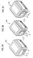
- Figs. 3A to 3C show a procedure of taking out the water supply tank 17 from the high-frequency heating apparatus 100.
- a push button 41 provided on this side on the side surface of the high-frequency heating apparatus 100 is pressed toward the inside of the high-frequency heating apparatus 100.
- a tank case door member 31 and the water supply tank 17 placed on this door member open outward from the side surface of the high-frequency heating apparatus 100.
- the tank case door member 31 corresponds to a tank support member in the Claims.
- the water supply tank 17 is pulled out to the front side of the high-frequency heating apparatus 100 thereby to be taken out.
- the water supply tank 17 is housed, it is inserted to the innermost in an opposite procedure to the above procedure, and the tank case door member 31 is pressed back.
- Fig. 4 is an exploded perspective view of the water supply tank unit in which the water supply tank is arranged on the side surface of the high-frequency heating apparatus 100
- Fig. 5 is an enlarged perspective view of the water supply tank
- Fig. 6 is a schematically exploded perspective view of the water supply tank unit, which explains the detailed structure of the water supply tank unit
- Fig. 7 is an explanatory view of a coupling part between a water supply port and a water inlet
- Fig. 8 is a sectional view showing a state where the water supply tank is inserted into the tank case door member
- Fig. 9 is an enlarged view of a bottom of the tank case door member
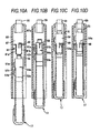
- Fig. 10 is an explanatory diagram showing a positional relation among the water supply tank, a guide wall, and the water inlet when the water supply tank is attached.
- a side surface heat insulating plate 25 is fixed with the predetermined space from a side wall plate inside the heating room to the outside of the high-frequency heating apparatus 100, and a tank case body 27 is attached to this side surface heat insulating plate 25 with the predetermined space.
- One side part of the tank case door member 31 is supported openably and closably about a support shaft by this tank case body 27. Further, between the tank case body 27 and the tank case door member 31, the water supply tank 17 is housed in a state where it is placed on the tank case door member 31. In the predetermined position on a bottom surface of the tank case body 27, a sponge 1 functioning as a water absorption means is bonded. The bonding position of the sponge 1 will be described later. On the outside of the tank case door member 31, a cover 12 is attached.
- the water supply tank 17 is formed in the shape of a flat rectangular parallelepiped, and comprises, as shown in Fig. 5, a tank body 51, a water supply port 55 corresponding to a water supply connection port in the Claims, and a tank lid member 57 attached to the tank body 51 detachably. Further, the water supply tank 17 has a raised bottom part 54 at a part of its bottom near the water supply port 55. Further, a part of a side surface of the tank lid member 57 of the water supply tank 17 has a function of guiding the water supply tank 17 to the predetermined holding position in a housing space S by contact with a guide wall 65a of the tank case door member 31.
- This water supply tank 17 is inserted into the tank case door member 31 as shown in Fig. 6, whereby the water supply port 55 is connected to a water inlet 59 of the tank case door member 31.
- the water inlet 59 corresponds to a water pour connection port in the Claims.
- the water inside the water supply tank 17 is fed from the water supply port 55 through the water supply passage into the evaporation tray 25 (refer to Fig. 2) provided at an end of the water supply passage.
- a base end circular tube part 43 of the water inlet 9 with which the water supply port 5 of the tank body 51 engages is provided with a pipe-sided shut-off valve 45 for preventing water leakage when the tank body 51 is detached.
- the water supply port 55 of the tank body 51 has not engaged with the base end circular tube part 43 yet, and both of a tank-sided shut-off valve 33 and the pipe-sided shut-off valve 45 close the flowing passage.
- a direction of a spring 33b for energizing a valve body 33a is opposite to a direction of a spring 45b for energizing a valve body 45a.
- the leading ends of the both valve bodies 33a and 45a abut on each other, and they give displacement to the respective opposite leading ends against the energizing power of the springs 33b and 45b, whereby the flowing passage is opened.
- an O-ring 49 is provided as a seal member for plugging a gap between the water supply port and the base end circular tube part 43.
- the tank case door member 31 into which this water supply tank 17 is inserted and attached comprises an upper surface part 65, a side surface part 68, and a bottom surface part 67, which form the housing space S.
- the upper surface part 65 and the bottom surface part 67 guide walls 65a and 67a which come into contact with the side surface of the water supply tank 17 to guide the attachment and detachment operations of the water supply tank 17 are provided in the attachment direction of the water supply tank 17.
- the tank case door member 31 includes the water inlet 59 connected to the water supply port 55 with the inserting operation of the water supply tank 17, a scupper 60 provided at the bottom part near the connection end of the water inlet 59, and a stanch rib 61 which surrounds the scupper 60 and stands from the bottom part.
- the protrusion height of this stanch rib 61 from the bottom part 67 (refer to Fig. 8) is set to a height h by which the flow of the water that has dropped is surely stanched. In this embodiment, this protrusion height h is about 3 mm.
- the stanch rib 61 is provided continuously from the side surface 68 to the guide wall 67a, and its intermediate part is formed nearly in C-shape.
- the area of the bottom part 67 near the scupper 60 is completely surrounded by the stanch rib 61, the side surface part 68, the guide wall 67a, and a sidewall having the water inlet 59.
- the stanch rib 61, the side surface part 68, the guide wall 67a, and the sidewall having the water inlet 59 constitute a water-storing wall.
- the stanch rib 61 has partially straight wall parts 61a and 61b which become parallel to the inserting direction of the water supply tank 17, that is, the guide wall 67a and the side surface part 68.
- the bottom surface part 67 of the tank case door member 31, as shown in Fig. 8, has an elastic fitting piece 63 in which a projection 69 over which the water supply tank 17 gets in the attachment process in the predetermined holding position in the housing space S to be locked is formed.
- the projection 69 corresponds to a projection part in the Claims.
- the elastic fitting piece 63 is formed by providing a groove around the elastic fitting piece 63 except its base part at the bottom part 67, and this groove is used as the scupper 60.
- a spaced height H between the bottom surface part 67 of the tank case door member 31 and the bottom in the raised bottom part 54 of the tank body 51 is set to a height by which contact of the bottom of the tank body 51 with the water is prevented even in case that water adheres to the top of the stanch rib 61.
- this spaced height H is about 5 mm.
- the flow of the water that has flown out from the water inlet 59 or the water supply port 55 is stanched by the stanch rib 61, the side surface part 68, the guide wall 67a, and the side wall having the water inlet 59, it always flows through the scupper 60 to the outside of the tank case door member 31 and is absorbed in the sponge 1. Namely, since the flow of the water is stanched by the stanch rib 61, it does not spread over other regions of the bottom surface part 67 than the region partitioned by the stanch rib 61. Further, the water absorbed in the sponge 1 is evaporated by heat generated when the high-frequency heating apparatus 100 operates. In place of the sponge, an unwoven fabric that is good in water absorbability may be used. Further, the scupper 60 may be provided for the bottom part under the connection end of the water inlet 59.
- the raised bottom part 54 defines when the water supply tank 17 is held by the tank case door member 31, space by which the stanch rib 61 of the tank case door member 31 and the bottom surface part of the tank case door member 31 surrounded by the stanch rib 61 are not brought into contact with the bottom of the water supply tank 17. Further, in the raised bottom part 54, as shown in Fig. 5, a projection 54a for locking the water supply tank 17 when the water supply tank 17 is attached to the tank case door member 31 is formed projectingly from the tank bottom surface to the downside.
- This raised bottom part 54 prevents, even if the water that has flown out of the water support port 55 or the water inlet 59 adheres to the stanch rib 61 or the bottom surface part 67 surrounded by the stanch rib 61, this water from adhering to the bottom part of the tank body 51.
- the raised bottom part 54 as shown in Fig. 5, has a projection 54a of which a part is protruded to the outside.
- the water supply tank 17 has bottom ribs 52a and 52b formed by protruding both edges of its bottom from the vicinity of the surface having the water supply port 55 in the longitudinal direction.
- the water supply tank 17 becomes a reinforcing member for the tank case door member 31, so that a part of the door (particularly end part 66 (refer to Fig. 6)) which is low in rigidity in a state of only the tank case door member 31 and difficult to close in pushing the door becomes easy to close.
- the water that has leaked from the water supply port 55 or the water inlet 59 is stanched by the stanch rib 61, without spreading over other regions of the bottom surface part 67 than the region partitioned by the stanch rib 61, the water drops from the scupper 60 and is absorbed in the sponge 1 bonded to the tank case body 27. Therefore, the water that has leaked can be treated so as not to remain into the tank case door member 31. In result, it is not misunderstood that the water is leaking from the water supply tank 17.
- the high-frequency heating apparatus with steam generating function 100 in the embodiment has the raised bottom part 54 at the bottom of the water supply tank 17.
- the spaced height between the top part of the stanch rib 61 of the tank case door member 31 and the bottom in the raised bottom part 54 is set to the height by which the contact of the bottom part of the tank body with the water is prevented even in case that the water adheres to the top of the stanch rib 61.
- the bottom ribs 52a and 52b of the water supply tank 17 come into slide-contact with the straight wall parts 61a and 61b of the tank case door member 31, the side surface part 68, and the guide wall 67a, and the water supply tank 17 is inserted into the tank case door member 31. Further, since the projection 69 of the tank case door member 31 and the projection 54a of the water supply tank 17 fit to each other, the water supply tank 17 is surely attached in the exact holding position.
- the water that has leaked when the water supply tank is detached can be treated so as not to remain.
Landscapes
- Physics & Mathematics (AREA)
- Electromagnetism (AREA)
- Electric Ovens (AREA)
- Cookers (AREA)
Abstract
Description
- The present invention relates to a water supply tank unit which is attached to a heating apparatus having a steam generating function and holds a water supply tank detachably. Moreover, the present invention relates to a heating apparatus having the water supply tank unit.
- A high-frequency heating apparatus provided with a high-frequency generating means which outputs a high frequency wave into a heating room in which a heated matter is housed, since it can efficiently heat the heated matter into the heating room in a short time, has spread rapidly as an electronic oven that is a heat cooking device for food material.
- However, heating by only use of high-frequency heating, limits heat cooking.
- Therefore, a high-frequency heating apparatus in which an electric heating device that generates heat into a heating room is added to enable oven heating has been proposed, and further a high-frequency heating apparatus with a steam generating function in which a steam supply mechanism for supplying heating steam into a heating room is added to enable also heat cooking by high-temperature steam has been recently proposed (for example, refer to Patent Reference 1: JP-A-54-115448).
- The steam supply mechanism of the high-frequency heating apparatus with a steam generating function comprises a water supply tank installed in an apparatus body through an tank support member detachably; a supplied water receiver provided into a heating room; and a heating means which heats this supplied water receiver and evaporates the water on the supplied water receiver. The water is, after a water supply port provided for the water supply tank has been inserted into a water inlet on the heating apparatus side, is supplied through a water supply pipe connected to this water inlet to the water receiver. However, in case that the water supply tank is pulled out from the tank support member, when the water supply port of the water supply tank separates from the water inlet on the heating apparatus side, a small amount of water may drop into the water inlet due to pressure of the water supply pipe path. Therefore, there is fear that this water that has dropped stays in a member for housing the water supply tank on the heating apparatus side and it enters in a circuit area such a power supply into the heating apparatus to influence the circuit area. Further, when the water that has leaked into the member for housing the water supply tank is attached to the bottom surface of the water supply tank, there is fear that a user misunderstands that the water is leaking from the water supply tank.
- In view to the above conventional circumstances, it is an object of the invention to provide a water supply tank unit which can treat the water that has leaked when the water supply tank is pulled out so that it does not remain.
- In order to achieve the above object, a water supply tank unit according to the invention, which is attached to a heating apparatus having a steam generating function and holds a water supply tank detachably, is characterized by comprising: a tank support member which has a water pour connection port connected to a water supply connection port with an inserting operation of the water supply tank, and a scupper provided at the bottom near the water pour connection port, and supports the inserted water supply tank; and a water absorption means provided below the scupper of the tank support member.
- Therefore, the water that has leaked from the water supply connection port or the water pour connection port comes out through the scupper from the tank support member, and is absorbed by the water absorption means. Consequently, in case that the water has leaked out into the tank support member, the leaking water can be treated so as not to remain. In result, it is not misunderstood that the water is leaking from the water supply tank.
- Further, the water supply tank unit of the invention is characterized in that at the bottom of the tank support member, a water-storing wall which surrounds the scupper and stands from the bottom is provided. Therefore, since the flow of the water that has leaked into the tank support member is stanched by the water storing wall, the water can be treated so as not to flow to the other area at the tank support member bottom than the area surrounded by the water storing wall.
- Further, The water supply tank unit of the invention is characterized in that the water storing wall has at its part a straight wall part parallel to the inserting direction of the water supply tank, and the water supply tank has at the tank bottom a guide which comes into slide-contact with the straight wall part in insertion into the tank support member. Therefore, since the guide located at the water supply tank bottom can be brought into slide-contact with the straight wall part of the tank support member to insert the water supply tank into the tank support member, the water supply tank is held in an exact position.
- Further, the water supply tank unit of the invention is characterized in that a raised bottom part which defines space for bringing the water storing wall of the tank support member and the bottom inside the water storing wall into no-contact with the tank bottom of the water supply tank when the water supply tank is held by the tank support member is formed at a part of the bottom of the water supply tank. Therefore, even in case that the water is attached onto the water storing wall or the bottom inside the water storing wall, this water is not attached onto the tank bottom, so that it is possible to prevent the water from leaking through the tank bottom to the outside of the water storing wall.
- Further, the water supply tank unit of the invention is characterized in that: the tank support member has at its bottom an elastic fitting piece provided with a projection part which fits to the water supply tank inserted to the tank support member and locks the water supply tank; and the elastic fitting piece is formed by providing a cavity around the elastic fitting piece except its base part at the bottom of the tank support member, and the cavity is used as the scupper. Therefore, the water supply tank is held surely in the tank support member by the projection part. Further, since the water that has leaked into the tank support member drops from the cavity around the elastic fitting piece and is absorbed by the water absorption member, labor and cost for forming the scupper newly can be omitted.
-
- Fig. 1 is an exterior perspective view of a high-frequency heating apparatus with a steam generating function according to the invention;
- Fig. 2 is a schematically front view showing a state where a door of the high-frequency heating apparatus with the steam generating function is opened;
- Figs. 3A to 3C are an explanatory views showing a procedure of taking out a water supply tank from the high-frequency heating apparatus with the steam generation function;
- Fig. 4 is an exploded perspective view of a water supply tank unit in which the water supply tank is arranged on a side surface of the high-frequency heating apparatus;
- Fig. 5 is an enlarged perspective view of the water supply tank;
- Fig. 6 is a schematically exploded perspective view of the water supply tank unit, which explains the detailed structure of the water supply tank unit;
- Figs. 7A and 7B are an explanatory views of a coupling part between a water supply port and a water inlet;
- Fig. 8 is a sectional view showing a state where the water supply tank is inserted into a tank case door member;
- Fig. 9 is an enlarged view of a bottom part of the tank case door member; and
- Figs. 10A to 10D are explanatory diagrams showing a positional relation among the water supply tank, a guide wall, and the water inlet when the water supply tank is attached.
-
- In the drawings, a
reference numeral 100 refers to a high-frequency heating apparatus; 17 to a water supply tank; 20 to a water supply tank unit; 7 to a steam generating part; 25 to an evaporation tray; 1 to a sponge; 35 to an operation member; 27 to a tank case body; 25 to a side surface heat insulating plate; 51 to a tank body; 57 to a tank lid member; 55 to a water supply port; 54 to a raised bottom part; 54a, 69 to a projection; 52a, 52b to a bottom rib; 59 to a water inlet; 61 to a stanch rib; 65 to an upper surface part; 65a, 67a to a guide wall; 60 to a scupper; 63 to an elastic fitting piece; 61a, 61b to a straight wall part; 66 to an end part; 67 to a bottom surface part; 68 to a side surface part; 31a, 31b to a sidewall; 51a, 51b to a guide rib; 33, 45 to a shut-off valve; 33a, 45a to a valve body; 33b, 45b to a spring; 49 to an O-ring; and 43 to a base end circular tube part. - Additionally, a reference sign S refers to a housing space.
- One embodiment of water supply tank structure of the invention will be described in detain below with reference to attached drawings.
- Herein, as an example of a heating apparatus having a steam generating function and being provided with a water supply tank unit, a high-frequency heating apparatus with a steam generating function is taken.
- Fig. 1 is an exterior perspective view of a high-frequency heating apparatus with a steam generating function according to the invention, and Fig. 2 is a schematically front view showing a state where an opening-and-closing door of the high-frequency heating apparatus with a steam generating function is opened.
- In the invention, as shown in Fig. 1, in order to give the steam generating function to a high-
frequency heating apparatus 100, a water supply tank unit in which a water supply tank for supplying water to a steam generating part is housed is arranged on a side surface of the high-frequency heating apparatus 100. The invention is characterized in that water leakage from this water supply tank unit, which is produced when the water supply tank unit is pulled out, does not have an influence on the high-frequency heating apparatus 100 side. Firstly, the basic structure of the high-frequency heating apparatus 100 as the heating apparatus and its working will be described. - This high-
frequency heating apparatus 100, as shown in Figs. 1 and 2, is a heat-cooking apparatus which supplies at least either a high-frequency wave (microwave) or steam to aheating room 3 in which a heated matter such as food material is housed to treat the heated matter by use of heat. The high-frequency heating apparatus 100 includes amagnetron 5 which outputs the high-frequency wave into theheating room 3 for housing the heated matter such as the food material therein, asteam generating part 7 which generates steam into theheating room 3, and awater supply tank 17 which is connected to a water supply passage to thesteam generating part 7 detachably. - The
heating room 3 is formed inside a box-shaped body case 10 of which a front surface is open, and an opening-and-closingdoor 13 which has a light-permeable window 13a, and opens and closes a heated matter outlet is provided on the front surface of thebody case 10. - The
magnetron 5 is arranged in space on the downside of theheating room 3, and astirrer vane 47 is provided in a position where the high-frequency wave generated from thismagnetron 5 is received. The high-frequency wave from themagnetron 5 is applied to the rotatingstirrer vane 47, whereby the high-frequency wave, being stirred in theheating room 3 by thestirrer vane 47, is supplied. - The
steam generating part 7 is provided with anevaporation tray 25 having a water storing recess that generates steam by heating. Below this evaporation tray 25, an evaporation tray heating heater for heating theevaporation tray 25, which is not shown, is provided. As the evaporation tray 25, an elongate tray made of, for example, stainless, or an aluminum block which is die casting-molded integrally with an evaporation tray heating heater and has a water storing recess on its upper surface may be used. Further, though oneevaporation tray 25 is provided in Fig. 2, the plural evaporation trays may be provided. - Figs. 3A to 3C show a procedure of taking out the
water supply tank 17 from the high-frequency heating apparatus 100. As shown in Fig. 3A, apush button 41 provided on this side on the side surface of the high-frequency heating apparatus 100 is pressed toward the inside of the high-frequency heating apparatus 100. Hereby, as shown in Fig. 3B, a tankcase door member 31 and thewater supply tank 17 placed on this door member open outward from the side surface of the high-frequency heating apparatus 100. The tankcase door member 31 corresponds to a tank support member in the Claims. Next, as shown in Fig. 3C, thewater supply tank 17 is pulled out to the front side of the high-frequency heating apparatus 100 thereby to be taken out. - Further, in case that the
water supply tank 17 is housed, it is inserted to the innermost in an opposite procedure to the above procedure, and the tankcase door member 31 is pressed back. - The structure of a water
supply tank unit 20 in which thewater supply tank 17 is detachably attached to the high-frequency heating apparatus 100 will be described below. - Fig. 4 is an exploded perspective view of the water supply tank unit in which the water supply tank is arranged on the side surface of the high-
frequency heating apparatus 100, Fig. 5 is an enlarged perspective view of the water supply tank, Fig. 6 is a schematically exploded perspective view of the water supply tank unit, which explains the detailed structure of the water supply tank unit, Fig. 7 is an explanatory view of a coupling part between a water supply port and a water inlet, Fig. 8 is a sectional view showing a state where the water supply tank is inserted into the tank case door member, Fig. 9 is an enlarged view of a bottom of the tank case door member, and Fig. 10 is an explanatory diagram showing a positional relation among the water supply tank, a guide wall, and the water inlet when the water supply tank is attached. - Onto the side surface of the high-
frequency heating apparatus 100, as shown in Fig. 4, a side surfaceheat insulating plate 25 is fixed with the predetermined space from a side wall plate inside the heating room to the outside of the high-frequency heating apparatus 100, and atank case body 27 is attached to this side surfaceheat insulating plate 25 with the predetermined space. - One side part of the tank
case door member 31 is supported openably and closably about a support shaft by thistank case body 27. Further, between thetank case body 27 and the tankcase door member 31, thewater supply tank 17 is housed in a state where it is placed on the tankcase door member 31. In the predetermined position on a bottom surface of thetank case body 27, asponge 1 functioning as a water absorption means is bonded. The bonding position of thesponge 1 will be described later. On the outside of the tankcase door member 31, acover 12 is attached. - Next, the
water supply tank 17 and the tankcase door member 31 will be described in detail. - The
water supply tank 17 is formed in the shape of a flat rectangular parallelepiped, and comprises, as shown in Fig. 5, atank body 51, awater supply port 55 corresponding to a water supply connection port in the Claims, and atank lid member 57 attached to thetank body 51 detachably. Further, thewater supply tank 17 has a raisedbottom part 54 at a part of its bottom near thewater supply port 55. Further, a part of a side surface of thetank lid member 57 of thewater supply tank 17 has a function of guiding thewater supply tank 17 to the predetermined holding position in a housing space S by contact with aguide wall 65a of the tankcase door member 31. - This
water supply tank 17 is inserted into the tankcase door member 31 as shown in Fig. 6, whereby thewater supply port 55 is connected to awater inlet 59 of the tankcase door member 31. Thewater inlet 59 corresponds to a water pour connection port in the Claims. In this state, the water inside thewater supply tank 17 is fed from thewater supply port 55 through the water supply passage into the evaporation tray 25 (refer to Fig. 2) provided at an end of the water supply passage. - Here, an engaging operation between the
water supply port 55 and thewater inlet 59 will be described. - In a base
end pipe part 29a of thewater inlet 59, as shown in Fig. 7A, a base endcircular tube part 43 of the water inlet 9 with which thewater supply port 5 of thetank body 51 engages is provided with a pipe-sided shut-offvalve 45 for preventing water leakage when thetank body 51 is detached. In the state shown in Fig. 7A, thewater supply port 55 of thetank body 51 has not engaged with the base endcircular tube part 43 yet, and both of a tank-sided shut-offvalve 33 and the pipe-sided shut-offvalve 45 close the flowing passage. - In the tank-sided shut-off
valve 33 and the pipe-sided shut-offvalve 45, a direction of aspring 33b for energizing a valve body 33a is opposite to a direction of aspring 45b for energizing avalve body 45a. In case that thewater supply port 55 of thetank body 51 is appropriately engaged with the base endcircular tube part 43, as shown in Fig. 7B, the leading ends of the bothvalve bodies 33a and 45a abut on each other, and they give displacement to the respective opposite leading ends against the energizing power of thesprings water supply port 55 of thetank body 51, an O-ring 49 is provided as a seal member for plugging a gap between the water supply port and the base endcircular tube part 43. - On the other hand, the tank
case door member 31 into which thiswater supply tank 17 is inserted and attached, as shown in Fig. 6, comprises anupper surface part 65, aside surface part 68, and abottom surface part 67, which form the housing space S. For theupper surface part 65 and thebottom surface part 67,guide walls water supply tank 17 to guide the attachment and detachment operations of thewater supply tank 17 are provided in the attachment direction of thewater supply tank 17. Further, the tankcase door member 31 includes thewater inlet 59 connected to thewater supply port 55 with the inserting operation of thewater supply tank 17, ascupper 60 provided at the bottom part near the connection end of thewater inlet 59, and a stanchrib 61 which surrounds thescupper 60 and stands from the bottom part. The protrusion height of this stanchrib 61 from the bottom part 67 (refer to Fig. 8) is set to a height h by which the flow of the water that has dropped is surely stanched. In this embodiment, this protrusion height h is about 3 mm. Further, the stanchrib 61 is provided continuously from theside surface 68 to theguide wall 67a, and its intermediate part is formed nearly in C-shape. Therefore, the area of thebottom part 67 near thescupper 60 is completely surrounded by the stanchrib 61, theside surface part 68, theguide wall 67a, and a sidewall having thewater inlet 59. Further, the stanchrib 61, theside surface part 68, theguide wall 67a, and the sidewall having thewater inlet 59 constitute a water-storing wall. Further, the stanchrib 61 has partiallystraight wall parts water supply tank 17, that is, theguide wall 67a and theside surface part 68. - The
bottom surface part 67 of the tankcase door member 31, as shown in Fig. 8, has an elasticfitting piece 63 in which aprojection 69 over which thewater supply tank 17 gets in the attachment process in the predetermined holding position in the housing space S to be locked is formed. Theprojection 69 corresponds to a projection part in the Claims. The elasticfitting piece 63 is formed by providing a groove around the elasticfitting piece 63 except its base part at thebottom part 67, and this groove is used as thescupper 60. In the state where thewater supply tank 17 is attached to the tankcase door member 31, a spaced height H between thebottom surface part 67 of the tankcase door member 31 and the bottom in the raisedbottom part 54 of thetank body 51 is set to a height by which contact of the bottom of thetank body 51 with the water is prevented even in case that water adheres to the top of the stanchrib 61. In this embodiment, this spaced height H is about 5 mm. Therefore, existence of space of height H-h (in this embodiment, about 2 mm) prevents, even if the water that has flown out of thewater support port 55 or thewater inlet 59 adheres to the stanchrib 61 or thebottom surface part 67 surrounded by the stanchrib 61, this water from adhering to the bottom part of thetank body 51. - Namely, when the
water supply tank 17 is pulled out from the tankcase door member 31, as shown in Fig. 9, a small amount of water remaining the connection part between thewater supply port 55 and thewater inlet 59 may flow out. At this time, the water droplet has flown out from thewater inlet 59 or thewater supply port 55 passes through thescupper 60 around the elasticfitting piece 63 and is absorbed in thesponge 1 bonded in the predetermined position of thetank case body 27 bottom. Thesponge 1 is bonded in a position of thetank case body 27 bottom which is under thescupper 60 when the tankcase door member 31 is closed. Since the flow of the water that has flown out from thewater inlet 59 or thewater supply port 55 is stanched by the stanchrib 61, theside surface part 68, theguide wall 67a, and the side wall having thewater inlet 59, it always flows through thescupper 60 to the outside of the tankcase door member 31 and is absorbed in thesponge 1. Namely, since the flow of the water is stanched by the stanchrib 61, it does not spread over other regions of thebottom surface part 67 than the region partitioned by the stanchrib 61. Further, the water absorbed in thesponge 1 is evaporated by heat generated when the high-frequency heating apparatus 100 operates. In place of the sponge, an unwoven fabric that is good in water absorbability may be used. Further, thescupper 60 may be provided for the bottom part under the connection end of thewater inlet 59. - Further, as shown in Figs. 6 and 8, the raised
bottom part 54 defines when thewater supply tank 17 is held by the tankcase door member 31, space by which the stanchrib 61 of the tankcase door member 31 and the bottom surface part of the tankcase door member 31 surrounded by the stanchrib 61 are not brought into contact with the bottom of thewater supply tank 17. Further, in the raisedbottom part 54, as shown in Fig. 5, aprojection 54a for locking thewater supply tank 17 when thewater supply tank 17 is attached to the tankcase door member 31 is formed projectingly from the tank bottom surface to the downside. This raisedbottom part 54 prevents, even if the water that has flown out of thewater support port 55 or thewater inlet 59 adheres to the stanchrib 61 or thebottom surface part 67 surrounded by the stanchrib 61, this water from adhering to the bottom part of thetank body 51. Further, the raisedbottom part 54, as shown in Fig. 5, has aprojection 54a of which a part is protruded to the outside. Further, thewater supply tank 17 hasbottom ribs water supply port 55 in the longitudinal direction. - Next, an operation of attaching the
water supply tank 17 in the predetermined holding position of the tankcase door member 31 will be described in detail. - As shown in Fig. 10A, in case that the
water supply tank 17 is inserted from a state where it is placed on thebottom surface 67 of the tankcase door member 31,guide ribs tank body 51 come into slide-contact with theside surface part 68 of the tankcase door member 31, whereby thewater supply tank 17 is positioned. Namely, thewater supply tank 17 is guided in the predetermined position of the tankcase door member 31 with the inserting operation. Further, when thewater supply tank 17 is pushed toward thewater inlet 59, as shown in Fig. 10B, the outer side surfaces of thestraight wall parts rib 61 standing at thebottom surface 67 of the tankcase door member 31 come into contact with the inner wall surfaces of thebottom ribs water supply tank 17, and thewater tank 17 slides while its position is being regulated. - Thereafter, as shown in Fig. 10C, insertion resistance increases in a position where the
projection 54a provided for the raisedbottom part 54 of thetank body 51 comes into contact with theprojection 69 provided for thebottom surface 67 of the tankcase door member 31, and the inserting operation is stopped once. When thewater supply tank 17 is further pushed toward thewater inlet 59 from this state, as shown in Fig. 10D, theprojections fitting piece 63, and flat rear end surfaces of theprojections water supply port 55 and thewater inlet 59 engage with each other, whereby thewater supply tank 17 is surely attached in the predetermined holding position. Further, by attaching thewater supply tank 17 to the tankcase door member 31, thewater supply tank 17 becomes a reinforcing member for the tankcase door member 31, so that a part of the door (particularly end part 66 (refer to Fig. 6)) which is low in rigidity in a state of only the tankcase door member 31 and difficult to close in pushing the door becomes easy to close. - In the high-frequency heating apparatus with a
steam generating function 100, since the flow of the water that has leaked from thewater supply port 55 or thewater inlet 59 is stanched by the stanchrib 61, without spreading over other regions of thebottom surface part 67 than the region partitioned by the stanchrib 61, the water drops from thescupper 60 and is absorbed in thesponge 1 bonded to thetank case body 27. Therefore, the water that has leaked can be treated so as not to remain into the tankcase door member 31. In result, it is not misunderstood that the water is leaking from thewater supply tank 17. - Further, the high-frequency heating apparatus with
steam generating function 100 in the embodiment has the raisedbottom part 54 at the bottom of thewater supply tank 17. In the state where thewater supply tank 17 is attached to the tankcase door member 31, the spaced height between the top part of the stanchrib 61 of the tankcase door member 31 and the bottom in the raisedbottom part 54 is set to the height by which the contact of the bottom part of the tank body with the water is prevented even in case that the water adheres to the top of the stanchrib 61. Consequently, even if the water that has flown out of thewater support port 55 or thewater inlet 59 adheres to the stanchrib 61 or thebottom surface part 67 surrounded by the stanchrib 61, this water never adheres to the bottom part of thetank body 51. Therefore, it is possible to prevent the water from leaking out to the outside of the stanchrib 61 through the tank bottom. - Further, the
bottom ribs water supply tank 17 come into slide-contact with thestraight wall parts case door member 31, theside surface part 68, and theguide wall 67a, and thewater supply tank 17 is inserted into the tankcase door member 31. Further, since theprojection 69 of the tankcase door member 31 and theprojection 54a of thewater supply tank 17 fit to each other, thewater supply tank 17 is surely attached in the exact holding position. - Further, since the water that has leaked into the tank
case door member 31 comes out from thescupper 60 forming the elasticfitting piece 63, labor and cost for newly forming the scupper can be omitted. - As described above, according to the water supply tank unit of the invention, the water that has leaked when the water supply tank is detached can be treated so as not to remain.
Claims (7)
- A water supply tank unit attached to a heating apparatus having a steam generating function and holds a water supply tank detachably, said tank unit comprising:a tank support member for supporting the water supply tank inserted to the water supply tank unit, said tank support member including: a water pour connection port connected to a water supply connection port with an inserting operation of the water supply tank; and a scupper provided at the bottom near the water pour connection port; anda water absorption means provided below the scupper of said tank support member.
- The water supply tank unit according to Claim 1,
wherein, at the bottom of said tank support member, a water storing wall which surrounds said scupper and stands from said bottom is provided. - The water supply tank unit according to Claim 2,
wherein said water storing wall has at its part a straight wall part parallel to the inserting direction of said water supply tank, and
wherein said water supply tank has at the tank bottom a guide which comes into slide-contact with said straight wall part in insertion into said tank support member. - The water supply tank unit according to Claim 2, further comprising:wherein, when the water supply tank is held by said tank support member, said raised bottom part defines space for bringing the water storing wall of said tank support member and the bottom inside the water storing wall into no-contact with the tank bottom of said water supply tank, when the water supply tank is held by said tank support member.a raised bottom part is formed at a part of the bottom of said water supply tank,
- The water supply tank unit according to Claim 3, further comprising:wherein, when the water supply tank is held by said tank support member, said raised bottom part defines space for bringing the water storing wall of said tank support member and the bottom inside the water storing wall into no-contact with the tank bottom of said water supply tank, when the water supply tank is held by said tank support member.a raised bottom part is formed at a part of the bottom of said water supply tank,
- The water supply tank unit according to any one of Claims 1 to 5, further comprising:wherein said elastic fitting piece is formed by providing a cavity around the elastic fitting piece except a base part at the bottom of said tank support member, andan elastic fitting piece provided at a bottom of said tank support member, said elastic fitting piece is provided with a projection part which fits to the water supply tank inserted to the tank support member and locks the water supply tank,
wherein said cavity is used as said scupper. - A heating apparatus comprising:wherein said water supply tank unit includes:a body case;a steam generating part in a heating room, including an evaporation tray; anda water supply tank unit attached to the body case, for holding a water supply tank detachably,a tank support member for supporting the water supply tank inserted into the water supply tank unit, said tank support member having: a water pour connection port connected to a water supply connection port with an inserting operation of the water supply tank; and a scupper provided at the bottom near the water pour connection port; anda water absorption means provided below the scupper of said tank support member.
Applications Claiming Priority (2)
| Application Number | Priority Date | Filing Date | Title |
|---|---|---|---|
| JP2003137473 | 2003-05-15 | ||
| JP2003137473A JP3843301B2 (en) | 2003-05-15 | 2003-05-15 | Water supply tank unit |
Publications (2)
| Publication Number | Publication Date |
|---|---|
| EP1477091A1 true EP1477091A1 (en) | 2004-11-17 |
| EP1477091B1 EP1477091B1 (en) | 2006-08-02 |
Family
ID=33028397
Family Applications (1)
| Application Number | Title | Priority Date | Filing Date |
|---|---|---|---|
| EP04011571A Expired - Lifetime EP1477091B1 (en) | 2003-05-15 | 2004-05-14 | Water supply tank unit and heating apparatus having the same |
Country Status (5)
| Country | Link |
|---|---|
| US (1) | US7171923B2 (en) |
| EP (1) | EP1477091B1 (en) |
| JP (1) | JP3843301B2 (en) |
| CN (1) | CN100385174C (en) |
| DE (1) | DE602004001710T2 (en) |
Cited By (4)
| Publication number | Priority date | Publication date | Assignee | Title |
|---|---|---|---|---|
| CN107440488A (en) * | 2017-09-29 | 2017-12-08 | 广东美的厨房电器制造有限公司 | Drawer type cooking apparatus |
| CN113854818A (en) * | 2021-10-08 | 2021-12-31 | 福建金源泉科技发展有限公司 | TRIZ-based water vapor system applying healthy water steaming oven and working method thereof |
| WO2022066491A3 (en) * | 2020-09-28 | 2022-05-05 | Anova Applied Electronics, Inc. | Combination oven |
| US11940332B2 (en) | 2019-09-23 | 2024-03-26 | Anova Applied Electronics, Inc. | Wet bulb temperature sensor system and method for direct measurement of wet bulb temperature in an oven |
Families Citing this family (16)
| Publication number | Priority date | Publication date | Assignee | Title |
|---|---|---|---|---|
| US8301019B2 (en) * | 2003-09-04 | 2012-10-30 | Bath & Body Works Brand Management, Inc. | Fragrance emanation system |
| KR100824006B1 (en) | 2006-12-29 | 2008-04-24 | 엘지전자 주식회사 | Steam generator in steam oven |
| DE102010002853B4 (en) | 2010-03-15 | 2022-02-03 | BSH Hausgeräte GmbH | Tank for a household appliance for preparing food and household appliance with such a tank |
| DE102010062888A1 (en) * | 2010-12-13 | 2012-06-14 | BSH Bosch und Siemens Hausgeräte GmbH | Water tank for a Dampfgargerät, Dampfgargerät with such a water tank and method for removing a water tank from a recording in a Dampfgargerät |
| FR3014665B1 (en) * | 2013-12-13 | 2016-02-05 | Seb Sa | METHOD AND APPARATUS FOR HEATING AND / OR COOKING STEAM FOOD |
| CN105351979B (en) * | 2015-10-08 | 2018-01-30 | 广东美的厨房电器制造有限公司 | The cistern assembly of micro-wave oven and micro-wave oven |
| CN105342371B (en) * | 2015-11-20 | 2017-09-19 | 广东美的厨房电器制造有限公司 | Pure steam stove |
| CN105326341B (en) * | 2015-11-20 | 2018-03-06 | 广东美的厨房电器制造有限公司 | Pure steam stove |
| TWI658804B (en) * | 2017-08-08 | 2019-05-11 | 日商夏普股份有限公司 | Heating conditioner |
| CN110200516A (en) | 2017-08-09 | 2019-09-06 | 沙克忍者运营有限责任公司 | Cooking system |
| CN109340836B (en) * | 2018-09-12 | 2020-06-09 | 洪东潦 | A domestic turntable microwave oven that uses pressure to change the position of the disc |
| WO2020176477A1 (en) | 2019-02-25 | 2020-09-03 | Sharkninja Operating Llc | Cooking system with guard |
| US11033146B2 (en) | 2019-02-25 | 2021-06-15 | Sharkninja Operating Llc | Cooking device and components thereof |
| CN110742496B (en) * | 2019-11-08 | 2025-03-11 | 珠海格力电器股份有限公司 | Water box assembly and steam oven |
| US11647861B2 (en) | 2020-03-30 | 2023-05-16 | Sharkninja Operating Llc | Cooking device and components thereof |
| CN116268997B (en) * | 2023-05-12 | 2023-09-01 | 杭州老板电器股份有限公司 | Draining board assembly and integrated water tank |
Citations (4)
| Publication number | Priority date | Publication date | Assignee | Title |
|---|---|---|---|---|
| JPS54115448A (en) | 1978-03-01 | 1979-09-08 | Mitsubishi Electric Corp | Cooking device |
| US5111740A (en) * | 1989-03-14 | 1992-05-12 | Peter Klein | Electrical apparatus useful to prepare a hot beverage |
| US5952634A (en) * | 1997-07-11 | 1999-09-14 | Hosiden Corporation | Drip-proof tactile push button switch |
| US6157006A (en) * | 1998-11-04 | 2000-12-05 | Metro Industries, Inc. | High humidity apparatus |
Family Cites Families (14)
| Publication number | Priority date | Publication date | Assignee | Title |
|---|---|---|---|---|
| JPS5321184A (en) | 1976-08-06 | 1978-02-27 | Takeda Chem Ind Ltd | Preparation of lactone compounds |
| JPS5444076A (en) | 1977-09-09 | 1979-04-07 | Matsushita Electric Industrial Co Ltd | Steam oven |
| JPS5444077A (en) | 1977-09-09 | 1979-04-07 | Matsushita Electric Industrial Co Ltd | Steam oven |
| JPS5448091A (en) | 1977-09-21 | 1979-04-16 | Fujikura Ltd | Connecting power cable conductor |
| JPS5850728B2 (en) | 1977-09-24 | 1983-11-12 | 松下電器産業株式会社 | steam oven |
| JPS5448090A (en) | 1977-09-26 | 1979-04-16 | Nippon Telegr & Teleph Corp <Ntt> | Armored submarine cable |
| JP2593507B2 (en) * | 1988-02-29 | 1997-03-26 | 株式会社東芝 | Air conditioner |
| US5636319A (en) * | 1988-12-21 | 1997-06-03 | Glucksman; Dov Z. | Portable and personal-sized warm air humidifier |
| JPH037924A (en) | 1989-06-05 | 1991-01-16 | Canon Inc | Camera provided with data imprinting function |
| US5242375A (en) * | 1992-02-27 | 1993-09-07 | Air-Shields, Inc. | Infant incubator and humidifier |
| US5228107A (en) * | 1992-07-29 | 1993-07-13 | Duracraft Corporation | Humidifier with safety shutoff |
| JPH07229627A (en) * | 1994-02-17 | 1995-08-29 | Sanyo Electric Co Ltd | Heating cooker |
| JP2001132955A (en) * | 1999-11-08 | 2001-05-18 | Sharp Corp | Combined cooker |
| US6591061B2 (en) * | 2000-10-03 | 2003-07-08 | Burton, Inc. | Humidifier |
-
2003
- 2003-05-15 JP JP2003137473A patent/JP3843301B2/en not_active Expired - Fee Related
-
2004
- 2004-05-14 DE DE602004001710T patent/DE602004001710T2/en not_active Expired - Lifetime
- 2004-05-14 US US10/846,409 patent/US7171923B2/en not_active Expired - Lifetime
- 2004-05-14 EP EP04011571A patent/EP1477091B1/en not_active Expired - Lifetime
- 2004-05-17 CN CNB200410043282XA patent/CN100385174C/en not_active Expired - Fee Related
Patent Citations (4)
| Publication number | Priority date | Publication date | Assignee | Title |
|---|---|---|---|---|
| JPS54115448A (en) | 1978-03-01 | 1979-09-08 | Mitsubishi Electric Corp | Cooking device |
| US5111740A (en) * | 1989-03-14 | 1992-05-12 | Peter Klein | Electrical apparatus useful to prepare a hot beverage |
| US5952634A (en) * | 1997-07-11 | 1999-09-14 | Hosiden Corporation | Drip-proof tactile push button switch |
| US6157006A (en) * | 1998-11-04 | 2000-12-05 | Metro Industries, Inc. | High humidity apparatus |
Cited By (5)
| Publication number | Priority date | Publication date | Assignee | Title |
|---|---|---|---|---|
| CN107440488A (en) * | 2017-09-29 | 2017-12-08 | 广东美的厨房电器制造有限公司 | Drawer type cooking apparatus |
| US11940332B2 (en) | 2019-09-23 | 2024-03-26 | Anova Applied Electronics, Inc. | Wet bulb temperature sensor system and method for direct measurement of wet bulb temperature in an oven |
| WO2022066491A3 (en) * | 2020-09-28 | 2022-05-05 | Anova Applied Electronics, Inc. | Combination oven |
| CN116209858A (en) * | 2020-09-28 | 2023-06-02 | 安诺华应用电子公司 | Combined oven |
| CN113854818A (en) * | 2021-10-08 | 2021-12-31 | 福建金源泉科技发展有限公司 | TRIZ-based water vapor system applying healthy water steaming oven and working method thereof |
Also Published As
| Publication number | Publication date |
|---|---|
| JP3843301B2 (en) | 2006-11-08 |
| DE602004001710D1 (en) | 2006-09-14 |
| JP2004340482A (en) | 2004-12-02 |
| CN100385174C (en) | 2008-04-30 |
| US20040255871A1 (en) | 2004-12-23 |
| CN1550711A (en) | 2004-12-01 |
| DE602004001710T2 (en) | 2006-11-30 |
| EP1477091B1 (en) | 2006-08-02 |
| US7171923B2 (en) | 2007-02-06 |
Similar Documents
| Publication | Publication Date | Title |
|---|---|---|
| EP1477091B1 (en) | Water supply tank unit and heating apparatus having the same | |
| KR101860714B1 (en) | Steam cooking apparatus | |
| CN101152049B (en) | Steam generator and heating cooking apparatus having the same | |
| KR101827831B1 (en) | Steam cooking apparatus | |
| US20200182485A1 (en) | Steam cooking device | |
| KR101859320B1 (en) | Water dispenser and steam generating device and cooking appliance therewith | |
| EP1403586B1 (en) | Water supply tank unit attached to a heating apparatus | |
| EP2775217A2 (en) | Steam cooking appliance | |
| US20200352382A1 (en) | Steam cooking appliance | |
| TWI639405B (en) | Heating conditioner | |
| CN102317691B (en) | Liquid tank and cooking device | |
| US20050087528A1 (en) | High frequency heating apparatus with steam generating function | |
| JP2006038316A (en) | Cooker | |
| JP5117215B2 (en) | Cooker | |
| JP3966362B2 (en) | High frequency cooker | |
| JP2011058710A (en) | Heating cooker | |
| US7870821B2 (en) | Coffee maker and microwave oven having the same | |
| KR100643894B1 (en) | Microwave rice cooker | |
| JP2004093068A (en) | Assembling structure of storage unit | |
| KR20140141075A (en) | A steam oven range | |
| US20080073338A1 (en) | High Frequency Cookware | |
| JP2004092862A (en) | Tube with hollow case and tank case door member provided therewith | |
| JP2006177661A (en) | High-frequency heating device with steam generation function | |
| KR100764275B1 (en) | Microwave | |
| JP2004340539A (en) | High frequency heating device with steam generation function |
Legal Events
| Date | Code | Title | Description |
|---|---|---|---|
| PUAI | Public reference made under article 153(3) epc to a published international application that has entered the european phase |
Free format text: ORIGINAL CODE: 0009012 |
|
| AK | Designated contracting states |
Kind code of ref document: A1 Designated state(s): AT BE BG CH CY CZ DE DK EE ES FI FR GB GR HU IE IT LI LU MC NL PL PT RO SE SI SK TR |
|
| AX | Request for extension of the european patent |
Extension state: AL HR LT LV MK |
|
| 17P | Request for examination filed |
Effective date: 20050128 |
|
| 17Q | First examination report despatched |
Effective date: 20050614 |
|
| AKX | Designation fees paid |
Designated state(s): DE FR GB |
|
| GRAP | Despatch of communication of intention to grant a patent |
Free format text: ORIGINAL CODE: EPIDOSNIGR1 |
|
| GRAS | Grant fee paid |
Free format text: ORIGINAL CODE: EPIDOSNIGR3 |
|
| GRAA | (expected) grant |
Free format text: ORIGINAL CODE: 0009210 |
|
| AK | Designated contracting states |
Kind code of ref document: B1 Designated state(s): DE FR GB |
|
| REG | Reference to a national code |
Ref country code: GB Ref legal event code: FG4D |
|
| RAP2 | Party data changed (patent owner data changed or rights of a patent transferred) |
Owner name: MATSUSHITA ELECTRIC INDUSTRIAL CO., LTD. |
|
| REF | Corresponds to: |
Ref document number: 602004001710 Country of ref document: DE Date of ref document: 20060914 Kind code of ref document: P |
|
| ET | Fr: translation filed | ||
| PLBE | No opposition filed within time limit |
Free format text: ORIGINAL CODE: 0009261 |
|
| STAA | Information on the status of an ep patent application or granted ep patent |
Free format text: STATUS: NO OPPOSITION FILED WITHIN TIME LIMIT |
|
| 26N | No opposition filed |
Effective date: 20070503 |
|
| REG | Reference to a national code |
Ref country code: FR Ref legal event code: PLFP Year of fee payment: 12 |
|
| PGFP | Annual fee paid to national office [announced via postgrant information from national office to epo] |
Ref country code: GB Payment date: 20150513 Year of fee payment: 12 Ref country code: DE Payment date: 20150506 Year of fee payment: 12 |
|
| PGFP | Annual fee paid to national office [announced via postgrant information from national office to epo] |
Ref country code: FR Payment date: 20150508 Year of fee payment: 12 |
|
| REG | Reference to a national code |
Ref country code: DE Ref legal event code: R119 Ref document number: 602004001710 Country of ref document: DE |
|
| GBPC | Gb: european patent ceased through non-payment of renewal fee |
Effective date: 20160514 |
|
| REG | Reference to a national code |
Ref country code: FR Ref legal event code: ST Effective date: 20170131 |
|
| PG25 | Lapsed in a contracting state [announced via postgrant information from national office to epo] |
Ref country code: DE Free format text: LAPSE BECAUSE OF NON-PAYMENT OF DUE FEES Effective date: 20161201 Ref country code: FR Free format text: LAPSE BECAUSE OF NON-PAYMENT OF DUE FEES Effective date: 20160531 |
|
| PG25 | Lapsed in a contracting state [announced via postgrant information from national office to epo] |
Ref country code: GB Free format text: LAPSE BECAUSE OF NON-PAYMENT OF DUE FEES Effective date: 20160514 |