EP1476727B1 - Appareil et procede de mesure des parametres d'un melange contenant des particules solides suspendues dans un fluide circulant dans un tuyau - Google Patents
Appareil et procede de mesure des parametres d'un melange contenant des particules solides suspendues dans un fluide circulant dans un tuyau Download PDFInfo
- Publication number
- EP1476727B1 EP1476727B1 EP03732047A EP03732047A EP1476727B1 EP 1476727 B1 EP1476727 B1 EP 1476727B1 EP 03732047 A EP03732047 A EP 03732047A EP 03732047 A EP03732047 A EP 03732047A EP 1476727 B1 EP1476727 B1 EP 1476727B1
- Authority
- EP
- European Patent Office
- Prior art keywords
- mixture
- pipe
- pressure
- fluid
- speed
- Prior art date
- Legal status (The legal status is an assumption and is not a legal conclusion. Google has not performed a legal analysis and makes no representation as to the accuracy of the status listed.)
- Expired - Lifetime
Links
Images


Classifications
-
- G—PHYSICS
- G01—MEASURING; TESTING
- G01F—MEASURING VOLUME, VOLUME FLOW, MASS FLOW OR LIQUID LEVEL; METERING BY VOLUME
- G01F1/00—Measuring the volume flow or mass flow of fluid or fluent solid material wherein the fluid passes through a meter in a continuous flow
- G01F1/704—Measuring the volume flow or mass flow of fluid or fluent solid material wherein the fluid passes through a meter in a continuous flow using marked regions or existing inhomogeneities within the fluid stream, e.g. statistically occurring variations in a fluid parameter
- G01F1/708—Measuring the time taken to traverse a fixed distance
- G01F1/7082—Measuring the time taken to traverse a fixed distance using acoustic detecting arrangements
-
- G—PHYSICS
- G01—MEASURING; TESTING
- G01F—MEASURING VOLUME, VOLUME FLOW, MASS FLOW OR LIQUID LEVEL; METERING BY VOLUME
- G01F1/00—Measuring the volume flow or mass flow of fluid or fluent solid material wherein the fluid passes through a meter in a continuous flow
- G01F1/66—Measuring the volume flow or mass flow of fluid or fluent solid material wherein the fluid passes through a meter in a continuous flow by measuring frequency, phase shift or propagation time of electromagnetic or other waves, e.g. using ultrasonic flowmeters
- G01F1/666—Measuring the volume flow or mass flow of fluid or fluent solid material wherein the fluid passes through a meter in a continuous flow by measuring frequency, phase shift or propagation time of electromagnetic or other waves, e.g. using ultrasonic flowmeters by detecting noise and sounds generated by the flowing fluid
-
- G—PHYSICS
- G01—MEASURING; TESTING
- G01F—MEASURING VOLUME, VOLUME FLOW, MASS FLOW OR LIQUID LEVEL; METERING BY VOLUME
- G01F1/00—Measuring the volume flow or mass flow of fluid or fluent solid material wherein the fluid passes through a meter in a continuous flow
- G01F1/66—Measuring the volume flow or mass flow of fluid or fluent solid material wherein the fluid passes through a meter in a continuous flow by measuring frequency, phase shift or propagation time of electromagnetic or other waves, e.g. using ultrasonic flowmeters
- G01F1/667—Arrangements of transducers for ultrasonic flowmeters; Circuits for operating ultrasonic flowmeters
- G01F1/668—Compensating or correcting for variations in velocity of sound
-
- G—PHYSICS
- G01—MEASURING; TESTING
- G01F—MEASURING VOLUME, VOLUME FLOW, MASS FLOW OR LIQUID LEVEL; METERING BY VOLUME
- G01F1/00—Measuring the volume flow or mass flow of fluid or fluent solid material wherein the fluid passes through a meter in a continuous flow
- G01F1/704—Measuring the volume flow or mass flow of fluid or fluent solid material wherein the fluid passes through a meter in a continuous flow using marked regions or existing inhomogeneities within the fluid stream, e.g. statistically occurring variations in a fluid parameter
- G01F1/708—Measuring the time taken to traverse a fixed distance
- G01F1/712—Measuring the time taken to traverse a fixed distance using auto-correlation or cross-correlation detection means
-
- G—PHYSICS
- G01—MEASURING; TESTING
- G01F—MEASURING VOLUME, VOLUME FLOW, MASS FLOW OR LIQUID LEVEL; METERING BY VOLUME
- G01F1/00—Measuring the volume flow or mass flow of fluid or fluent solid material wherein the fluid passes through a meter in a continuous flow
- G01F1/74—Devices for measuring flow of a fluid or flow of a fluent solid material in suspension in another fluid
Definitions
- This invention relates to an apparatus for measuring the flow passing within a pipe, and more particularly to an apparatus and method for measuring the speed of sound and/or vortical disturbances propagating in the flow, having particles suspended within a continuous fluid, to determine parameters, such as particle/fluid ratio, particle size and volumetric flow rate of the flow in pipes using acoustic and/or dynamic pressures.
- This invention provides a method to measure parameters of a fluid/particle mixture in a pipe that can be used in many applications, such as in chemical, pharmaceutical, petroleum and power generation industries.
- the invention provides a method to measure pulverized coal and air mixtures used in pulverized fuel delivery systems in place in a large percentage of coal fired boilers used in the power generation industry.
- the ability to measure the flow rate and composition of the air /coal mixture within the coal pipes is an important aspect of any system or strategy designed to optimize the performance of the PF delivery system.
- the industry recognizes this and therefore has been developing a wide variety of technologies to perform this measurement. These include probe based and sampling devices, as well as real time meters based on a wide variety of technologies including electrostatic charges, microwaves, and ultrasonic.
- Objects of the present invention include providing a system for measuring the speed of sound propagating through a particle/fluid mixture in pipes in coal fired boiler systems and related processes, for example, to determine particular parameters of the mixture.
- an apparatus for measuring at least one parameter of a particle/fluid mixture in a pipe includes a spatial array of at least two pressure sensors, disposed at different axial locations along the pipe. Each of the pressure sensors measures an unsteady pressure within the pipe at a corresponding axial location. Each of said sensors provides a pressure signal indicative of the unsteady pressure within the pipe at said axial location of a corresponding one of said sensors. A signal processor, responsive to said pressure signals, provides a signal indicative of the at least one parameter of the mixture in the pipe.
- a method for measuring at least one parameter of a particle/fluid mixture in a pipe includes measuring unsteady pressures within the pipe at at least two predetermined axial measurement locations along the pipe to provide a pressure signal indicative of the unsteady pressure within the pipe at each of the at least two predetermined axial measurement locations. Further the method includes calculating the at least one parameter of the particle/fluid mixture in the pipe using the unsteady pressure measured at the axial measurement locations.
- a flow meter 10,70 embodying the present invention measures a number of parameters/characteristics of a mixture 12 of solid particles suspended within a continuous fluid flowing within a pipe or conduit 14, wherein a fluid is defined as a liquid and/or a gas.
- the flow meter may be configured and programmed to measure the speed of sound propagating through the mixture or measure the vortical disturbances propagating through the mixture. In some instances, the flow meter 10 may be configured to measure both the speed of sound and the vortical disturbances.
- the flow meter can measure at least one of the following parameters of the mixture flow 12: the fluid/particle concentration (volumetric phase fraction), the volumetric flow rate, the size of the solid particles, the mass flow of the mixture and the velocity of the mixture.
- the flow meter 10,70 measures the unsteady pressures created by the speed of sound (SOS) and/or the vortical disturbances propagating through the mixture flowing in the pipe 14, which will be described in greater detail hereinafter.
- SOS speed of sound
- the solid particles of the mixture 12 may be of any size, shape and material.
- the particles may be small in size as in the form of a powder, in a granular form, or greater in size.
- the flow meter 10,70 can be used in any application that carries solid particles suspended in a fluid through a pipe, such as in chemical, pharmaceutical, petroleum and power generation applications.
- the present invention is well suited to measure the parameters (e.g. air/coal ratio, particle size) for power generation systems that use pulverized coal to fire the furnace a steam boiler system.
- PF Pulverized Fuel
- a representative PF delivery system 1 is shown in a coal fired boiler system 2 in Fig. 2 .
- the coal is pulverized in a mill 3 and entrained in air produced by many means, such as a fan 4 to transport the PF/air mixture via pipes 12 for delivery to the furnace 6.
- Typical furnaces can have >50 coal pipes, each 30,5-50,8 m (12.20 inch) in diameter.
- a large utility boiler >300 Mw can have 4-11 pulverizing mills feeding the furnace.
- the ability of the PF delivery system to deliver the proper amount of fuel and air to the furnace through these multiple coal pipes, both collectively and individually, has a strong influence on the performance and emissions from the coal fired boiler.
- the flow meter 10 embodying the present invention is capable of measuring the fuel to air ratio and particle size of the pulverized coal provided to the furnace to thereby provide feedback to the operator to provide more efficient combustion of the coal.
- the flow meter10,70 of the present invention may be configured and programmed to measure and process the detected unsteady pressures P 1 (t) - P N (t) created by acoustic waves and/or vortical disturbances propagating through the mixture to determine parameters of the mixture flow 12.
- One such flow meter 10 is shown in Fig. 1 that measures the speed of sound (SOS) of one-dimensional sound waves propagating through the fluid/particle mixture to determine the composition the mixture, namely the liquid/particle ratio of the mixture.
- SOS speed of sound
- the flow meter is also capable of determining the average size of the particles, velocity of the mixture, and the volumetric flow rate of the mixture. It is known that sound propagates through various mediums at various speeds in such fields as SONAR and RADAR fields.
- the speed of sound of a mixture within a pipe 14 may be determined using a number of known techniques, such as those set forth in U.S. Patent Application Serial No. 09/344,094 , entitled “Fluid Parameter Measurement in Pipes Using Acoustic Pressures", filed June 25, 1999, and U.S. Patent Application Serial No. 10/007,749 , entitled “Fluid Parameter Measurement in Pipes Using Acoustic Pressures", filed November 7, 2001, each of which are incorporated herein by reference.
- the present invention utilizes at least one flow meter 10 to determine various parameters of the liquid/particle mixture, wherein one of the parameters is the speed at which sound travels within the mixture pipe system as will be more fully described herein below.
- the speed of sound propagating through the mixture 12 is measured by passively listening to the flow with an array of unsteady pressure sensors to determine the speed at which one-dimensional compression waves propagate through a liquid/particle mixture contained within the pipe 14.
- the flow meter 10 has an array of at least three acoustic pressure sensors 15,16,17, located at three locations x 1 ,x 2 ,x 3 axially along the pipe 14.
- the sensor array may include more than three pressure sensors as depicted by pressure sensor 18 at location x N .
- the pressure generated by the acoustic waves may be measured through holes in the pipe 14 ported to external pressure sensors 15 - 18 or by other techniques discussed hereinafter.
- the pressure sensors 15-18 provide pressure time-varying signals P 1 (t),P 2 (t),P 3 (t),P N (t) on lines 20,21,22,23 to a signal processing unit 30 to known Fast Fourier Transform (FFT) logics 26,27,28, 29, respectively.
- FFT Fast Fourier Transform
- the FFT logics 26 - 29 calculate the Fourier transform of the time-based input signals P 1 (t) - P N (t) and provide complex frequency domain (or frequency based) signals P 1 (w),P 2 (w),P 3 (w),P N (w) on lines 32,33,34,35 indicative of the frequency content of the input signals.
- any other technique for obtaining the frequency domain characteristics of the signals P 1 (t) - P N (t) may be used.
- the cross-spectral density and the power spectral density may be used to form a frequency domain transfer functions (or frequency response or ratios) discussed hereinafter.
- the frequency signals P 1 (w) - P N (w) are fed to a mix -Mx Calculation Logic 38 which provides a signal to line 40 indicative of the speed of sound of the mixture a mix (discussed more hereinafter).
- the a mix signal is provided to map (or equation) logic 42, which converts a mix to a percent composition of the PF/air mixture and provides a %Comp signal to line 44 indicative thereof (as discussed hereinafter).
- the calculation logic 40 may also provide a signal Mx to line 46 indicative of the Mach number Mx.
- A,B are the frequency-based complex amplitudes of the right and left traveling waves, respectively
- x is the pressure measurement location along a pipe
- k r ,k l are wave numbers for the right and left travelling waves, respectively, which are defined as: k r ⁇ ⁇ a mix ⁇ 1 1
- the data from the array of sensors may be processed in any domain, including the frequency/spatial domain, the temporal/spatial domain, the temporal/wave-number domain or the wave-number/frequency (k- ⁇ ) domain.
- any known array processing technique in any of these or other related domains may be used if desired.
- signal processing unit 30 may be implemented in software (using a microprocessor or computer) and/or firmware, or may be implemented using analog and/or digital hardware, having sufficient memory, interfaces, and capacity to perform the functions described herein.
- Acoustic pressure sensors 15-18 sense acoustic pressure signals that, as measured, are lower frequency (and longer wavelength) signals than those used for ultrasonic flow meters of the prior art, and thus the current invention is more tolerant to inhomogeneities in the flow, such as roping and other time and space domain inhomogeneities within the flow, even where entrenchment or coal "roping" is unlikely such as following a bend.
- the term "roping” is a term known to those skilled in this art which represents a form of severe spatial and temporal mal-distribution induced in mixture flows of widely different component densities. It is a condition where a large portion of the coal flow is in a band running along one side of pipe 14.
- the present invention incorporates the compliance of the pipe 14 to determine the effective speed of sound of the pipe/PF/air mixture system.
- the acoustic pressure signals P 1 (t) - P N (t) are generated within the PF/air mixture of the pipe 14 by a variety of non-discrete sources such as remote machinery, mills, fans 4 ( Fig. 2 ), valves, elbows, as well as the PF/air mixture flow itself. It is this last source, the PF/air mixture 12 flowing within the pipe 14, which is a generic source of acoustic noise that assures a minimum level of acoustics for any PF/air mixture piping systems for which the present invention takes unique advantage.
- the flow generated acoustics increase with mean flow velocity and the overall noise levels (acoustic pressure levels) are a function of the generating mechanism and the damping mechanism. As such, no external discrete noise source is required within the present invention and thus may operate using passive listening. While the flow meter 10 passively listens to the mixture flow 12, the present invention contemplates adding an acoustic source to inject a desire acoustic wave into the flow to be measured, such as by compressing, vibrating and/or tapping the pipe, to name a few examples.
- the pipe 14 may be desirable for the pipe 14 to exhibit a certain amount of pipe compliance.
- the axial test section 50 of the pipe 14 along where the sensors 15 - 18 are located may be made as rigid as possible.
- the thickness of the wall of the test section 50 may be made to have a predetermined thickness, or the test section 50 may be made of a very rigid material, e.g., steel, titanium, Kevlar ® , ceramic, or other material with a high modulus.
- the pressure sensor spacing may be known or arbitrary and that as few as two sensors are required if certain information is known about the acoustic properties of the PF/air mixture piping system.
- the pressure sensors are spaced sufficiently such that the entire length of the array (aperature) is at least a significant fraction of the measured wavelength of the acoustic waves being measured.
- the acoustic wavelength to be measured is a function of at least the size and mass of the particles, and the viscosity of the fluid. The greater the size and mass of the particles and/or the less viscous the fluid, the greater the spacing of the sensors is needed. Conversely, the smaller the size and mass of the particles and/or the more viscous the fluid, the shorter the spacing of the sensors is needed.
- the flow meter 10 measures the speed of sound of one-dimensional sound waves propagating through the fluid/particle mixture to determine the composition of the mixture.
- the speed of sound propagating through dilute solid/air mixtures can be directly related to the mass fraction particles of the flow.
- a typical PF fuel delivery system 1 may operate with an air to coal mass ratio of 1.5 to 2.5.
- PF delivery systems operate with an air-to-coal mass ratio of 1.5 to 2.5 with coal density of 1200 to 1400 kg/m 3 compared to 1.2 kg/m 3 for air at standard atmospheric conditions.
- meeting the desired mass ratio results in a very dilute mixture of coal on a volumetric basis, on the order of one part in 1000 by volume.
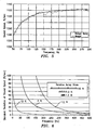
- the speed at which sound travels within the piping system of a representative coal / air mixtures is shown in Fig. 4 as a function of air /coal mass ratio.
- the pure air was assumed to have a density of 1.2 kg/m ⁇ 3 and a sound speed of 365.9 m/s and the coal was assumed to have a density of 1400 kg/m ⁇ 3 and a sound speed of 2439 m/s.
- the effect of increasing coal fraction, i.e. decreasing air/coal ratio is to decrease the sound speed.
- adding coal particles effectively mass loads the mixture, while not appreciably changing the compressibility of the air.
- the relation between mixture sound speed and air / coal ratio is well behaved and monatomic.
- Fig. 5 shows the measured speed of sound as a function of frequency for an actual coal/air mixture 12.
- the sound speed was measured utilizing passive listening techniques of the present invention as described herein.
- the frequency dependence of the sound speed was determined by applying a Capon array-processing algorithm at multiple narrow frequency ranges between 50-300 Hz thereby determining a frequency specific acoustic propagation velocity.
- the data was obtained wherein the coal/air mixture was flowing at nominally 30,5 m/s (100 ft/sec) with an air-to-coal mass ratio equal to 1.8.
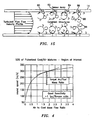
- the coal particles were nominally 50 ⁇ m in size, representative of pulverized coal typically used in power generation and other industrial applications.
- a magnified view of the coal particles that were used for this test is shown in Fig. 3 .
- the sound speed increases with increasing frequency and asymptotes toward a constant value.
- the sound speed asymptote at higher frequency is essentially the sound speed of air only with no influence of the suspended particles.
- the sound speed of the coal/air mixture has not reached the quasi-steady limit at the lowest frequency for which sound speed was measured.
- the sound speed is continuing to decrease at the lower frequency limit.
- An important discovery of the present invention is that the speed at which sound propagates through dilute particles suspended in a continuous fluid is said to be dispersive. As defined herein, the speed at which acoustic waves propagate through dispersive mixtures varies with frequency.
- the aperture should be at least a significant fraction of a wavelength of the sound speed of interest.
- sound speed data was recorded with an array of four sensors, spaced at 12 inches, for a total aperture of three feet.
- a 305 m/s (1000 ft/sec) sound wave has a wavelength of 6,10 m (20 ft).
- the dispersive nature of the system utilizes a first principles model of the interaction between the air and particles.
- This model is viewed as being representative of a class of models that seek to account for dispersive effects
- Other models could be used to account for dispersive effects without altering the intent of this disclosure (for example, see the paper titled "Viscous Attenuation of Acoustic Waves in Suspensions" by R.L. Gibson, Jr. and M.N. Toksöz), which is incorporated herein by reference.
- the model allows for slip between the local velocity of the continuous fluid phase and that of the particles.
- the drag force on the particles by the continuous fluid is modeled by a force proportional to the difference between the local fluid velocity and that of the fluid particles and is balanced by inertial force:
- K proportionality constant
- U f fluid velocity
- U p particle velocity
- ⁇ p particle density
- v p particle volume.
- the effect of the force on the continuous fluid phase by the fluid particles is modeled as a force term in the axial momentum equation.
- C d drag coefficient
- a p frontal area of particle
- ⁇ f fluid density.
- K 3 ⁇ ⁇ ⁇ D p
- a mix ⁇ a f ⁇ 1 1 + ⁇ p ⁇ ⁇ p ⁇ f ⁇ 1 + ⁇ 2 ⁇ ⁇ p 2 ⁇ v p 2 K 2
- the fluid SOS, density ( ⁇ ) and viscosity ( ⁇ ) are those of the pure phase fluid
- v p is the volume of individual particles
- ⁇ p is the volumetric phase fraction of the particles in the mixture.
- Figs. 7 and 8 show the dispersive behavior for coal/air mixtures with parameters typical of those used in pulverized coal deliver systems.
- Fig. 7 shows the predicted behavior for nominally 50 ⁇ m size coal in air for a range of air-to-fuel ratios.
- the effect of air-to-fuel ratio is well defined in the low frequency limit.
- the effect of the air-to-fuel ratio becomes indistinguishable at higher frequencies, approaching the sound speed of the pure air at high frequencies (above ⁇ 100 Hz).
- Fig. 8 shows the predicted behavior for a coal/air mixture with an air-to-fuel ratio of 1.8 with varying particle size. This figure illustrates that particle size has no influence on either the low frequency limit (quasi-steady) sound speed, or on the high frequency limit of the sound speed. However, particle size does have a pronounced effect in the transition region.
- Figs. 7 and 8 illustrate an important aspect of the present invention. Namely, that the dispersive properties of dilute mixtures of particles suspended in a continuous fluid can be broadly classified into three frequency regimes: low frequency range, high frequency range and a transitional frequency range. Although the effect of particle size and air-to-fuel ratio are inter-related, the predominant effect of air-to-fuel ratio is to determine the low frequency limit of the sound speed to be measured and the predominate effect of particle size is to determine the frequency range of the transitional regions. As particle size increases, the frequency at which the dispersive properties appear decreases. For typical pulverized coal applications, this transitional region begins at fairly low frequencies, ⁇ 2Hz for 50 ⁇ m size particles.
- the frequency range for which the no-slip, quasi-steady approximation is valid is a function of a variety of parameters including particle size, continuous phase viscosity, particle shape and particle density.
- the sound speed was measured using an embodiment of the present invention having eight sensors at 20.5 inch spacing, averaged from 20-40 Hz, for a range of air-to-coal mass ratios.
- the sound speed predicted for the coal/air mixtures using the quasi-steady model are also presented. As shown, although the general trend is captured, i.e. sound speed decreases with increased coal loading, the error is significant, rendering a first principle interpretation, based on a quasi-steady model inadequate.
- the dispersion relation predicts the sound speed with asymptote towards the sound speed of the pure fluid.
- the high frequency limit is independent of both particle size and air-to-fuel ratio.
- the flow meter 10 of the present invention includes the ability to accurately determine the average particle size of the coal in the PF/air mixture within the pipe 14 and the air to fuel ratio.
- the propagation of one dimensional sound wave through multiphase mixtures is influenced by the effective mass and the effective compressibility of the mixture.
- the degree to which the no-slip assumption applies is a strong function of particle size and frequency. In the limit of small particles and low frequency, the no-slip assumption is valid. As the size of the particles increases and the frequency of the sound waves increase, the non-slip assumption becomes increasing less valid.
- the increase in slip with frequency causes dispersion, or, in other words, the sound speed of the mixture to change with frequency.
- dispersive characteristic of a mixture will provide a measurement of the average particle size, as well as, the air to fuel ratio (particle/fluid ratio) of the mixture.
- a mix ⁇ a f ⁇ 1 1 + ⁇ p ⁇ ⁇ p ⁇ f ⁇ 1 + ⁇ 2 ⁇ ⁇ p 2 ⁇ v p 2 K 2
- Fig. 11 The results of the optimization procedure applied to data recorded from an array of sensors listening to flow in a six inch circular duct, 50 ⁇ m particle size, 30,5 m/s (100 ft/sec) air flow rate with an air-to-fuel ratio of 1.8 is shown in Fig. 11 .
- the measured and optimized-model-predicted sound speed is shown.
- the model captures the transitional frequency range well and provides a good estimate of the air-to-fuel ratio.
- the flow meter 10 further includes the ability to measure of volumetric flow rate of the mixture by comparing the difference of the speed of one dimensional sound waves propagating with and against the mean flow.
- This method of determining the volumetric flow rate of the particle/fluid mixture 12 within pipe 14 relies on the interaction of the mean flow with the acoustic pressure field.
- a L velocity of a left traveling acoustic wave apparent to a stationary observer
- a mix fluid speed of sound (if the fluid were not flowing)
- u the mean flow velocity (assumed to be flowing from left to right in this instance).
- the flow meter 10 utilizes similar processing algorithms as those employed herein before.
- the temporal and spatial frequency content of sound propagating within the process piping 14 is related through a dispersion relationship.
- ⁇ k a mix .
- ⁇ is the temporal frequency in rad/sec
- a mix is the speed at which sound propagates within the process piping.
- the acoustic power is located along two acoustic ridges, one for the sound traveling with the flow at a speed of a mix + V mix and one for the sound traveling against the flow at a speed of a mix - V mix .
- Fig. 13 shows a k- ⁇ plot generated for acoustic sound field of a coal/air mixture flowing through a pipe. Two acoustic ridges are clearly evident. Each of the slopes of the two depicted acoustic ridges respectively defines the speed of sound traveling with and against the mean flow.
- the sonar flow meter 10 of Fig. 1 is configured and programmed to measure and utilize the speed of sound propagating through a particle/fluid mixture 12 flowing in a pipe 14 to determine volumetric flow rate.
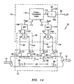
- a flow meter 70 embodying the present invention includes the ability to measure volumetric flow rate of the mixture by measuring the unsteady pressures generated by vortical disturbance 88 propagating in the mixture.
- the flow meter 70 uses one or both of the following techniques to determine the convection velocity of the vortical disturbances within the fluid/particle mixture 12 by:
- Fig. 15 shows a representative schematic of a velocity profile and coherent vortical flow structures 88 present in fully developed turbulent pipe flow 12.
- the vortical structures 88 are superimposed over time averaged velocity profile within the pipe 14 and contain temporally and spatially random fluctuations with magnitudes typically less than 10% percent of the mean flow velocity.
- volumetrically averaged flow velocity is of interest.
- A is the cross sectional area of the pipe and Q is the volumetric flow rate. In fact, given the velocity profile within the pipe, little flow is actually moving at this speed.
- Turbulent pipes flows are highly complex flows. Predicting the details of any turbulent flow is one of nature's great-unsolved problems. However, much is known regarding the statistical properties of the flow. For instance, turbulent pipe flows contain self-generating, coherent vortical structures often termed "turbulent eddies". The maximum length scale of these eddies is set by the diameter of the pipe. These structures remain coherent for several pipe diameters downstream, eventually breaking down into progressively smaller eddies until the energy is dissipated by viscous effects.
- the flow meter 70 of Fig. 14 determines the convection velocity of the vortical disturbances within the fluid/particle mixture by cross correlating unsteady pressure variations using an array of unsteady pressure sensors, similar to that shown in U.S. Patent Application Serial No. 10/007,736, filed November 8, 2001 , entitled “Flow Rate Measurement Using Unsteady Pressures", which is incorporated herein by reference.
- the flow meter 70 includes a sensing section 72 along a pipe 12 and a signal processing unit 74.
- the pipe (or conduit) 14 has two measurement regions 76,78 located a distance ⁇ X apart along the pipe 14.
- At the first measurement region 76 are two unsteady (or dynamic or ac) pressure sensors 80,82, located a distance X 1 apart, capable of measuring the unsteady pressure in the pipe 14, and at the second measurement region 78, are two other unsteady pressure sensors 84,86, located a distance X 2 apart, capable of measuring the unsteady pressure in the pipe 14.
- Each pair of pressure sensors 80,82 and 84,86 act as spatial filters to remove certain acoustic signals from the unsteady pressure signals, and the distances X 1 ,X 2 are determined by the desired filtering characteristic for each spatial filter, as discussed hereinafter.
- the flow meter 70 of the present invention measures velocities associated with unsteady flow fields and/or pressure disturbances represented by 88 associated therewith relating to turbulent eddies (or vortical flow fields), inhomogeneities in the flow (such as bubbles, slugs, and the like), or any other properties of the flow, fluid, or pressure, having time varying or stochastic properties that are manifested at least in part in the form of unsteady pressures.
- the vortical flow fields are generated within the fluid of the pipe 14 by a variety of non-discrete sources such as remote machinery, pumps, valves, elbows, as well as the fluid flow itself.
- the fluid flowing within the pipe that is a generic source of vortical flow fields primarily caused by the shear forces between the fluid and the wall of the pipe that assures a minimum level of disturbances for any fluid piping systems for which the present invention takes unique advantage.
- the flow generated vortical flow fields generally increase with mean flow velocity and do not occur at any predeterminable frequency.
- no external discrete vortex generating source is required within the present invention and thus may operate using passive detection.
- the pressure sensor spacing may be known or arbitrary and that as few as two sensors are required if certain information is known about the acoustic properties of the system as will be more fully described herein below.
- the vortical flow fields 88 are, in general, comprised of pressure disturbances having a wide variation in length scales and which have a variety of coherence length scales such as that described in the reference " Sound and Sources of Sound", A. P.Dowling et al, Halsted Press, 1983 , which is incorporated by reference to the extend of understanding the invention. Certain of these vortical flow fields 88 convect at or near/or related to the mean velocity of at least one of the elements within a mixture flowing in a pipe.
- the vortical pressure disturbances 15 that contain information regarding convection velocity have temporal and spatial length scales as well as coherence length scales that differ from other disturbances in the flow.
- the present invention utilizes these properties to preferentially select disturbances of a desired axial length scale and coherence length scale as will be more fully described hereinafter.
- the terms vortical flow field and vortical pressure field will be used to describe the above-described group of unsteady pressure fields having temporal and spatial length and coherence scales described herein.
- the pressures P 1 ,P 2 ,P 3 ,P 4 may be measured through holes in the pipe 14 ported to external pressure sensors or by other techniques discussed hereinafter.
- the pressure sensors 80,82,84,86 provide time-based pressure signals P 1 (t),P 2 (t),P 3 (t), P 4 (t) on lines 90 - 93, respectively, to signal processing unit 74 which provides a convection velocity signal U c (t) on a line 96 which is related to an average flow rate U f (t) of the fluid flowing in the pipe 14.
- signal processing unit 74 may be implemented in software (using a microprocessor or computer) and/or firmware, or may be implemented using analog and/or digital hardware, having sufficient memory, interfaces, and capacity to perform the functions described herein.
- the pressure signal P 1 (t) on the line 90 is provided to a positive input of a summer 100 and the pressure signal P 2 (t) on the line 91 is provided to a negative input of the summer 100.
- the pressure sensors 80,82 together with the summer 100 create a spatial filter 76.
- the line 104 is fed to bandpass filter 108, which passes a predetermined passband of frequencies and attenuates frequencies outside the passband.
- the passband of the filter 108 is set to filter out (or attenuate) the dc portion and the high frequency portion of the input signals and to pass the frequencies therebetween.
- Other passbands may be used in other embodiments, if desired.
- Passband filter 108 provides a filtered signal P asf 1 on a line 112 to Cross-Correlation Logic 116, described hereinafter.
- the pressure signal P 3 (t) on the line 92 is provided to a positive input of a summer 102 and the pressure signal P 4 (t) on the line 93 is provided to a negative input of the summer 102.
- the pressure sensors 83,84 together with the summer 102 create a spatial filter 78.
- the line 106 is fed to a bandpass filter 110, similar to the bandpass filter 108 discussed hereinbefore, which passes frequencies within the passband and attenuates frequencies outside the passband.
- the filter 110 provides a filtered signal P asf 2 on a line 114 to the Cross-Correlation Logic 116.
- the signs on the summers 100,102 may be swapped if desired, provided the signs of both summers are swapped together.
- the pressure signals P 1 ,P 2 ,P 3 ,P 4 may be scaled prior to presentation to the summers 100,102.
- the Cross-Correlation Logic 116 calculates a known time domain cross-correlation between the signals P asf1 and P asf2 on the lines 112,114, respectively, and provides an output signal on a line 118 indicative of the time delay ⁇ it takes for an vortical flow field 88 (or vortex, stochastic, or vortical structure, field, disturbance or perturbation within the flow) to propagate from one sensing region 76 to the other sensing region 78.
- vortical flow disturbances are coherent dynamic conditions that can occur in the flow which substantially decay (by a predetermined amount) over a predetermined distance (or coherence length) and convect (or flow) at or near the average velocity of the fluid flow.
- the vortical flow field 88 also has a stochastic or vortical pressure disturbance associated with it.
- the vortical flow disturbances 88 are distributed throughout the flow, particularly in high shear regions, such as boundary layers (e.g., along the inner wall of the pipe 14) and are shown herein as discrete vortical flow fields 88. Because the vortical flow fields (and the associated pressure disturbance) convect at or near the mean flow velocity, the propagation time delay ⁇ is related to the velocity of the flow by the distance ⁇ X between the measurement regions 76,78, as discussed hereinafter.
- an optional circumferential groove may be used in the inner diameter of the pipe 14 to help generate unsteady flow fields in the form of vertices into the flow.
- the groove is not required for the present invention to operate, due to vortex generation which naturally occurs along the pipe inner wall, as discussed hereinbefore.
- a plurality of axially spaced circumferential grooves may be used.
- the dimensions and geometry of the groove(s) 70 may be set based on the expected flow conditions and other factors. Other techniques may be used as vortex generators if desired including those that may protrude within the inner diameter of pipe 14.
- a spacing signal ⁇ X on a line 120 indicative of the distance ⁇ X between the sensing regions 76,78 is divided by the time delay signal ⁇ on the line 118 by a divider 122 which provides an output signal on the line 96 indicative of the convection velocity U c (t) of the fluid flowing in the pipe 14, which is related to (or proportional to or approximately equal to) the average (or mean) flow velocity U f (t) of the fluid, as defined below:
- U c t ⁇ X / ⁇ ⁇ U f t
- the convection velocity U c (t) may then be calibrated to more precisely determine the mean velocity U f (t) if desired.
- the result of such calibration may require multiplying the value of the convection velocity U c (t) by a calibration constant (gain) and/or adding a calibration offset to obtain the mean flow velocity U f (t) with the desired accuracy.
- Other calibration may be used if desired. For some applications, such calibration may not be required to meet the desired accuracy.
- the velocities U f (t),U c (t) may be converted to volumetric flow rate by multiplying the velocity by the cross-sectional area of the pipe.
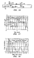
- cross-correlation may be used to determine the time delay ⁇ between two signals y 1 (t),y 2 (t) separated by a known distance ⁇ X, that are indicative of quantities 80 that convect with the flow (e.g., density perturbations, concentration perturbations, temperature perturbations, vortical pressure disturbances, and other quantities).
- the signal y 2 (t) lags behind the signal y 1 (t) by 0.15 seconds.
- a time domain cross-correlation is taken between the two signals y 1 (t),y 2 (t)
- the result is shown in Fig. 17 as a curve 124.
- the highest peak 126 of the curve 124 shows the best fit for the time lag ⁇ between the two signals y 1 (t),y 2 (t) is at 0.15 seconds which matches the reference time delay shown in Fig. 17 .
- the vortical pressure disturbances observed at the downstream location are substantially a time lagged version of the vortical pressure disturbances observed at the upstream location.
- the unsteady pressure disturbances P vortical can be masked by the acoustic pressure disturbances P acoustic and the other types of pressure disturbances P other .
- the presence of the acoustic pressure disturbances that propagate both upstream and downstream at the speed of sound in the fluid (sonic velocity) can prohibit the direct measurement of velocity from cross-correlation of direct vortical pressure measurements.
- the present invention uses temporal and spatial filtering to precondition the pressure signals to effectively filter out the acoustic pressure disturbances P acoustic and other long wavelength (compared to the sensor spacing) pressure disturbances in the pipe 14 at the two sensing regions 76,78 and retain a substantial portion of the vortical pressure disturbances P vortical associated with the vortical flow field 88 and any other short wavelength (compared to the sensor spacing) low frequency pressure disturbances P other .
- the low frequency pressure disturbances P other are small, they will not substantially impair the measurement accuracy of P vortical .
- the P vortical dominated signals from the two regions 76,78 are then cross-correlated to determine the time delay ⁇ between the two sensing locations 76,78. More specifically, at the sensing region 72, the difference between the two pressure sensors 80,82 creates a spatial filter 76 that effectively filters out (or attenuates) acoustic disturbances for which the wavelength ⁇ of the acoustic waves propagating along the fluid is long (e.g., ten-to-one) compared to the spacing X 1 between the sensors.
- Other wavelength to sensor spacing ratios may be used to characterize the filtering, provided the wavelength to sensor spacing ratio is sufficient to satisfy the two-to-one spatial aliasing Nyquist criteria.
- the spatial filter 76 also applies to the second spatial filter 78 comprising the other pair of pressure signals P 3 ,P 4 , axially spaced a distance X 2 apart, which provides the differenced vortical pressure signal P as2 .
- the second technique of determining the convection velocity of the vortical disturbances within the fluid/ particle mixture is by characterisizing the convective ridge of the vortal disturbances using an array of unsteady pressure sensors, as will be described.
- the sonar flow metering methodology uses the convection velocity of coherent structure with turbulent pipe flows to determine the volumetric flow rate.
- the convection velocity of these eddies 88 is determined by applying sonar arraying processing techniques to determine the speed at which the eddies convect past an axial array of unsteady pressure measurements distributed along the pipe 14.
- the sonar-based algorithms determine the speed of the eddies by characterizing both the temporal and spatially frequency characteristics of the flow field.
- ⁇ is the temporal frequency in rad/sec
- U convect is the convection velocity.
- K- ⁇ plots are essentially three-dimensional power spectra in which the power of a sound field is decomposed into bins corresponding to specific spatial wave numbers and temporal frequencies.
- the power associated with a pressure field convecting with the flow is distributed in regions which satisfies the dispersion relationship developed above. This region is termed “the convective ridge” (Beranek, 1992) and the slope of this ridge on a k-w plot indicates the convective velocity of the pressure field. This suggests that the connective velocity of turbulent eddies, and hence flow rate within a pipe, can be determined by constructing a k- ⁇ plot from the output of a phased array of sensor and identifying the slope of the convective ridge.
- Fig. 19 shows an example of a k- ⁇ plot generated from a phased array of pressure sensors.
- the power contours show a well-defined convective ridge.
- a parametric optimization method was used to determine the "best" line representing the slope of the convective ridge 100. For this case, a slope of 4,33m/s (14.2 ft/sec) was determined.
- the intermediate result of the optimization procedure is displayed in the insert, showing that optimized value is a unique and well-defined optima.
- Fig. 19 illustrates the fundamental principle behind sonar based flow measure, namely that axial arrays of pressure sensors can be used in conjunction with sonar processing techniques to determine the speed at which naturally occurring turbulent eddies convect within a pipe.
- the pressure sensors 15-18 described herein may be any type of pressure sensor, capable of measuring the unsteady (or ac or dynamic) pressures within a pipe 14, such as piezoelectric, optical, capacitive, resistive (e.g., Wheatstone bridge), accelerometers (or geophones), velocity measuring devices, displacement measuring devices, etc. If optical pressure sensors are used, the sensors 15-18 may be Bragg.grating based pressure sensors, such as that described in US Patent Application, Serial No. 08/925,598 , entitled "High Sensitivity Fiber Optic Pressure Sensor For Use In Harsh Environments", filed Sept. 8, 1997, now U.S. Patent 6,016,702 .
- the sensors 14 may be electrical or optical strain gages attached to or embedded in the outer or inner wall of the pipe which measure pipe wall strain, including microphones, hydrophones, or any other sensor capable of measuring the unsteady pressures within the pipe 14.
- the sensors 14 may be connected individually or may be multiplexed along one or more optical fibers using wavelength division multiplexing (WDM), time division multiplexing (TDM), or any other optical multiplexing techniques.
- WDM wavelength division multiplexing
- TDM time division multiplexing
- the pressure sensors including electrical strain gages, optical fibers and/or gratings among others as described herein, may be attached to the pipe by adhesive, glue, epoxy, tape or other suitable attachment means to ensure suitable contact between the sensor and the pipe 14.
- the sensors may alternatively be removable or permanently attached via known mechanical techniques such as mechanical fastener, spring loaded, clamped, clam shell arrangement, strapping or other equivalents.
- the strain gages, including optical fibers and/or gratings may be embedded in a composite pipe. If desired, for certain applications, the gratings may be detached from (or strain or acoustically isolated from) the pipe 14 if desired.
- any other strain sensing technique may be used to measure the variations in strain in the pipe, such as highly sensitive piezoelectric, electronic or electric, strain gages attached to or embedded in the pipe 14.
- a piezo-electronic pressure transducer may be used as one or more of the pressure sensors 15-18 and it may measure the unsteady (or dynamic or ac) pressure variations inside the pipe 14 by measuring the pressure levels inside of the pipe.
- the sensors 14 comprise pressure sensors manufactured by PCB Piezotronics.
- one pressure sensor there are integrated circuit piezoelectric voltage mode-type sensors that feature built-in microelectronic amplifiers, and convert the high-impedance charge into a low-impedance voltage output.
- Model 106B manufactured by PCB Piezotronics which is a high sensitivity, acceleration compensated integrated circuit piezoelectric quartz pressure sensor suitable for measuring low pressure acoustic phenomena in hydraulic and pneumatic systems. It has the unique capability to measure small pressure changes of less than 6,89 Pa (0.001 psi) under high static conditions.
- the 106B has a 43,51 ⁇ V/Pa (300 mV/psi) sensitivity and a resolution of 91 dB 0,689 Pa (0.0001 psi).
- the pressure sensors incorporate a built-in MOSFET microelectronic amplifier to convert the high-impedance charge output into a low-impedance voltage signal.
- the sensor is powered from a constant-current source and can operate over long coaxial or ribbon cable without signal degradation.
- the low-impedance voltage signal is not affected by triboelectric cable noise or insulation resistance-degrading contaminants.
- Power to operate integrated circuit piezoelectric sensors generally takes the form of a low-cost, 24 to 27 VDC, 2 to 20 mA constant-current supply.
- a data acquisition system of the present invention may incorporate constant-current power for directly powering integrated circuit piezoelectric sensors.
- piezoelectric pressure sensors are constructed with either compression mode quartz crystals preloaded in a rigid housing, or unconstrained tourmaline crystals. These designs give the sensors microsecond response times and resonant frequencies in the hundreds of kHz, with minimal overshoot or ringing. Small diaphragm diameters ensure spatial resolution of narrow shock waves.
- the output characteristic of piezoelectric pressure sensor systems is that of an AC-coupled system, where repetitive signals decay until there is an equal area above and below the original base line. As magnitude levels of the monitored event fluctuate, the output remains stabilized around the base line with the positive and negative areas of the curve remaining equal.
- each of the pressure sensors 15-18 of the flow meters 10,70 may include a piezoelectric sensor 104 -107 that provides a piezoelectric material 110 to measure the unsteady pressures of the fluid/particle mixture 12 as shown in Fig. 20 .
- the piezoelectric material such as the polymer, polarized fluoropolymer, polyvinylidene fluoride (PVDF), measures the strain induced within the process pipe 14 due to unsteady pressure variations within the process mixture 12. Strain within the pipe is transduced to an output voltage or current by the attached piezoelectric sensors 104-107.
- the PVDF material 110 is adhered to the outer surface of a steel strap 112 that extends around and clamps onto the outer surface of the pipe 14.
- the piezoelectric sensing element is typically conformal to allow complete or nearly complete circumferential measurement of induced strain.
- the sensors can be formed from PVDF films, co-polymer films, or flexible PZT sensors, similar to that described in "Piezo Film Sensors technical Manual” provided by Measurement Specialties, Inc., which is incorporated herein by reference. The advantages of this technique are the following:
- While the present invention is capable of measuring solid particles suspended in a fluid, one will appreciate that other multi-phase mixtures or flows may be measured using an array of sensors, such as steam flow. It is further recognize the effects of dispersion on large solid particles in a fluid would be similar to large droplets of a liquid dispersed in a gas or air, and thus similar considerations when measuring the steam quality and droplet size should be addressed.
Landscapes
- Physics & Mathematics (AREA)
- Fluid Mechanics (AREA)
- General Physics & Mathematics (AREA)
- Acoustics & Sound (AREA)
- Electromagnetism (AREA)
- Investigating Or Analyzing Materials By The Use Of Ultrasonic Waves (AREA)
- Measuring Volume Flow (AREA)
Claims (30)
- Appareil (10) pour mesurer au moins un paramètre d'un mélange particules/fluide (12) dans un conduit (14), comprenant :un réseau spatial d'au moins deux capteurs de pression (15, 16, 17, 18) qui sont disposés à différents endroits en direction axiale le long du conduit (14) et qui mesurent chacun une pression variable au sein du conduit (14) à un endroit correspondant en direction axiale (X1, X2, X3, XN), chacun desdits capteurs générant un signal de pression indiquant la pression variable régnant au sein du conduit (14) audit endroit en direction axiale (X1, X2, X3, XN) d'un desdits capteurs correspondants (15, 16, 17, 18) ; etun processeur de signaux (30) sensible auxdits signaux de pression,caractérisé en ce que le processeur de signaux (30) est conçu pour déterminer la vitesse du son qui se propage à travers le mélange (12) en fonction de la fréquence afin de caractériser les propriétés de dispersion du mélange (12) et pour comparer les propriétés de dispersion du mélange (12) à un modèle de dispersion du mélange (12) afin d'obtenir un signal indicateur dudit au moins un paramètre du mélange (12) dans le conduit (14).
- Appareil (10) selon la revendication 1, dans lequel les capteurs de pression (15, 16, 17, 18) sont choisis parmi le groupe comprenant des dispositifs piézo-électriques, des dispositifs optiques, des dispositifs capacitifs, des dispositifs résistifs, des dispositifs de mesure de la vitesse, des dispositifs de mesure du déplacement ainsi que des accéléromètres ou des géophones.
- Appareil (10) selon la revendication 1, dans lequel les capteurs de pression (15, 16, 17, 18) englobent des jauges ou des capteurs qui se basent sur la déformation.
- Appareil (10) selon la revendication 1, dont le modèle de dispersion est dérivé par voie analytique.
- Appareil (10) selon la revendication 1, dans lequel le modèle de dispersion dérivé par voie analytique est un modèle :

dans lequelαmix représente la vitesse du son qui se propage à travers le mélange ;αf représente la vitesse du son qui se propage à travers le fluide ;ρf représente la densité du fluide ;ρp représente la densité des particules ;ω représente la fréquence ;νp représente le volume des particules ;K représente une constante de proportionnalité ;ϕp représente la fraction de la phase volumétrique. - Appareil (10) selon la revendication 1, conçu pour mesurer un mélange produit(s) solide(s)/fluide (12) y compris un mélange choisi parmi le groupe comprenant un mélange produit(s) solide(s)/liquide (12) et un mélange produit(s) solide(s)/air (12).
- Appareil (10) selon la revendication 1, conçu pour mesurer au moins un paramètre du mélange (12), y compris au moins un paramètre choisi parmi le groupe comprenant le rapport produit(s) solide(s)/liquide et la granulométrie moyenne des particules du mélange (12).
- Appareil (10) selon la revendication 1, dans lequel le processeur de signaux (30) est en outre conçu pour caractériser les propriétés de dispersion du mélange (12) en réponse à la viscosité du fluide, à la densité du fluide, à la densité des particules, au volume estimé des particules et à la fraction estimée de la phase volumétrique du mélange (12).
- Appareil (10) selon la revendication 1, dans lequel la caractéristique dispersive du mélange (12) procure une mesure de la granulométrie moyenne et du rapport produit(s) solide(s)/fluide du mélange (12).
- Appareil (10) selon la revendication 1, qui englobe la capacité de mesurer le débit volumétrique du mélange (12) par comparaison de la différence des vitesses des ondes acoustiques unidimensionnelles qui se propagent avec le débit moyen et de celles qui se déplacent à l'encontre de celui-ci.
- Appareil (10) selon la revendication 1, dans lequel chaque capteur est conçu pour mesurer une pression acoustique et procure un signal indiquant un bruit acoustique au sein du conduit (14).
- Appareil (10) selon la revendication 1, dans lequel ledit processeur de signaux (30) est conçu pour fournir un signal basé sur la fréquence pour chacun desdits signaux de pression.
- Appareil (10) selon la revendication 1, comprenant au moins trois desdits capteurs (15, 16, 17).
- Appareil (10) selon la revendication 1, dans lequel les capteurs de pression du réseau (15, 16, 17, 18) sont suffisamment espacés les uns des autres pour que la longueur totale du réseau représente au moins une fraction significative de la longueur d'onde mesurée des ondes acoustiques que l'on mesure.
- Appareil (10) selon la revendication 1, dans lequel le processeur de signaux (30) est conçu pour définir une crête acoustique dans le plan κ-ω et détermine la pente de ladite au moins une portion d'une crête acoustique afin de déterminer la vitesse du son qui se propage à travers le mélange (12).
- Procédé pour mesurer au moins un paramètre d'un mélange produit(s) solide(s)/fluide (12) dans un conduit (14), ledit procédé comprenant le fait de :mesurer des pressions variables au sein du conduit (14) à au moins deux endroits de mesure prédéterminés en direction axiale (X1, X2, X3, XN) le long du conduit (14) pour procurer un signal de pression indiquant la pression variable régnant au sein du conduit (14) à chacun desdits au moins deux endroits de mesure prédéterminés en direction axiale (X1, X2, X3, XN) ;caractérisé en ce que ledit procédé comprend en outre le fait de :calculer ledit au moins un paramètre du mélange produit(s) solide(s)/fluide (12) dans le conduit (14) en utilisant la pression variable mesurée aux endroits de mesure en direction axiale (X1, X2, X3, XN) en déterminant la vitesse du son qui se propage à travers le mélange (12) en fonction de la fréquence afin de caractériser les propriétés de dispersion du mélange (12) et en comparant les propriétés de dispersion du mélange (12) à un modèle de dispersion du mélange (12).
- Procédé selon la revendication 16, dans lequel les capteurs de pression (15, 16, 17, 18) sont choisis parmi le groupe comprenant des dispositifs piézo-électriques, des dispositifs optiques, des dispositifs capacitifs, des dispositifs résistifs, des dispositifs de mesure de la vitesse, des dispositifs de mesure du déplacement ainsi que des accéléromètres ou des géophones.
- Procédé selon la revendication 16, qui utilise un modèle de dispersion que l'on dérive par voie analytique.
- Procédé selon la revendication 16, qui utilise un modèle de dispersion dérivé par voie analytique, à savoir un modèle :

dans lequelαmix représente la vitesse du son qui se propage à travers le mélange ;αf représente la vitesse du son qui se propage à travers le fluide ;ρf représente la densité du fluide ;ρp représente la densité des particules ;ω représente la fréquence ;νp représente le volume des particules ;K représente une constante de proportionnalité ;ϕp représente la fraction de la phase volumétrique. - Procédé selon la revendication 16, pour mesurer un mélange produit(s) solide(s)/fluide (12) y compris un mélange choisi parmi le groupe comprenant un mélange produit(s) solide(s)/liquide (12) et un mélange produit(s) solide(s)/air (12).
- Procédé selon la revendication 16, pour mesurer au moins un paramètre du mélange (12), y compris au moins un paramètre choisi parmi le groupe comprenant le rapport produit(s) solide(s)/liquide et la dimension moyenne du/des produits solides du mélange (12).
- Procédé selon la revendication 16, dans lequel on utilise une corrélation croisée pour déterminer le temps de retard entre deux signaux, séparés d'une distance connue, qui fournissent des indications de valeurs (80) qui se déplacent par convection avec l'écoulement, y compris au moins un élément choisi parmi le groupe des perturbations de densité, des perturbations de concentration, des perturbations de température, des perturbations de pression tourbillonnaire.
- Procédé selon la revendication 16, dans lequel la caractéristique dispersive du mélange (12) fournit une mesure de la granulométrie moyenne et du rapport produit(s) solide(s)/fluide du mélange (12).
- Procédé selon la revendication 16, qui englobe la capacité de mesurer le débit volumétrique du mélange (12) par comparaison de la différence des vitesses des ondes acoustiques unidimensionnelles qui se propagent avec le débit moyen et de celles qui se déplacent à l'encontre de celui-ci.
- Procédé selon la revendication 16, dans lequel chaque capteur mesure une pression acoustique et procure un signal indiquant un bruit acoustique au sein du conduit (14).
- Procédé selon la revendication 16, dans lequel ledit processeur de signaux (30) fournit un signal basé sur la fréquence pour chacun desdits signaux de pression.
- Procédé selon la revendication 16, dans lequel on utilise au moins trois desdits capteurs.
- Procédé selon la revendication 16, dans lequel on utilise des capteurs de pression du réseau (15, 16, 17, 18) qui sont suffisamment espacés les uns des autres pour que la longueur totale du réseau représente au moins une fraction significative de la longueur d'onde mesurée des ondes acoustiques que l'on mesure.
- Procédé selon la revendication 16, dans lequel le procédé englobe le fait de déterminer la meilleure ligne pour représenter la pente d'une crête acoustique dans le plan κ-ω et pour déterminer la pente de ladite portion de la crête acoustique afin de déterminer la vitesse du son qui se propage à travers le mélange.
- Procédé selon la revendication 16, dans lequel les capteurs de pression (15, 16, 17, 18) englobent des jauges ou des capteurs qui se basent sur la déformation.
Applications Claiming Priority (11)
| Application Number | Priority Date | Filing Date | Title |
|---|---|---|---|
| US35123202P | 2002-01-23 | 2002-01-23 | |
| US351232P | 2002-01-23 | ||
| US35978502P | 2002-02-26 | 2002-02-26 | |
| US359785P | 2002-02-26 | ||
| US37584702P | 2002-04-24 | 2002-04-24 | |
| US375847P | 2002-04-24 | ||
| US42543602P | 2002-11-12 | 2002-11-12 | |
| US425436P | 2002-11-12 | ||
| US42672402P | 2002-11-15 | 2002-11-15 | |
| US426724P | 2002-11-15 | ||
| PCT/US2003/001925 WO2003062759A1 (fr) | 2002-01-23 | 2003-01-23 | Appareil et procede de mesure des parametres d'un melange contenant des particules solides suspendues dans un fluide circulant dans un tuyau |
Publications (2)
| Publication Number | Publication Date |
|---|---|
| EP1476727A1 EP1476727A1 (fr) | 2004-11-17 |
| EP1476727B1 true EP1476727B1 (fr) | 2012-03-14 |
Family
ID=27617920
Family Applications (1)
| Application Number | Title | Priority Date | Filing Date |
|---|---|---|---|
| EP03732047A Expired - Lifetime EP1476727B1 (fr) | 2002-01-23 | 2003-01-23 | Appareil et procede de mesure des parametres d'un melange contenant des particules solides suspendues dans un fluide circulant dans un tuyau |
Country Status (6)
| Country | Link |
|---|---|
| EP (1) | EP1476727B1 (fr) |
| CN (1) | CN100582681C (fr) |
| AT (1) | ATE549602T1 (fr) |
| CA (1) | CA2474071C (fr) |
| ES (1) | ES2382073T3 (fr) |
| WO (1) | WO2003062759A1 (fr) |
Cited By (1)
| Publication number | Priority date | Publication date | Assignee | Title |
|---|---|---|---|---|
| EP1546662B1 (fr) * | 2002-04-24 | 2018-12-05 | Cidra Corporate Services, Inc. | Appareil et procede de mesure de parametres d'un melange comportant des particules solides en suspension dans un fluide s'ecoulant dans un tuyau |
Families Citing this family (20)
| Publication number | Priority date | Publication date | Assignee | Title |
|---|---|---|---|---|
| AU2003287645A1 (en) | 2002-11-12 | 2004-06-03 | Cidra Corporation | An apparatus having an array of piezoelectric film sensors for measuring parameters of a process flow within a pipe |
| US7882750B2 (en) | 2003-08-01 | 2011-02-08 | Cidra Corporate Services, Inc. | Method and apparatus for measuring parameters of a fluid flowing within a pipe using a configurable array of sensors |
| CA2537897C (fr) * | 2003-08-01 | 2014-06-10 | Cidra Corporation | Procede et appareil de mesure de parametres d'un fluide a haute temperature circulant dans une conduite, utilisant un ensemble de detecteurs piezo-electriques de flux |
| CA2537904C (fr) * | 2003-08-01 | 2013-11-19 | Cidra Corporation | Procede et appareil de mesure de parametres d'un debit de fluide dans une conduite au moyen d'un reseau configurable de capteurs |
| CA2537800C (fr) * | 2003-08-08 | 2013-02-19 | Cidra Corporation | Capteur a base de piezo-cable permettant de mesurer des pressions instables a l'interieur d'un tuyau |
| US7367239B2 (en) | 2004-03-23 | 2008-05-06 | Cidra Corporation | Piezocable based sensor for measuring unsteady pressures inside a pipe |
| WO2007009097A1 (fr) | 2005-07-13 | 2007-01-18 | Cidra Corporation | Procede et appareil de mesure de parametres d'un ecoulement de liquide au moyen d'un reseau de capteurs |
| US7379792B2 (en) * | 2005-09-29 | 2008-05-27 | Rosemount Inc. | Pressure transmitter with acoustic pressure sensor |
| DE102007062908A1 (de) | 2007-12-21 | 2009-06-25 | Endress + Hauser Flowtec Ag | Verfahren und System zur Bestimmung mindestens einer Prozessgröße eines strömenden Mediums |
| AU2009249092B2 (en) * | 2008-05-20 | 2015-05-07 | Cidra Corporate Services, Inc. | Applications of pump performance monitoring |
| DE102010064278A1 (de) | 2010-12-28 | 2012-06-28 | Endress + Hauser Flowtec Ag | Verfahren zur Dichtekorrektur in Wirbelströmungsmessgerät |
| US9442094B2 (en) * | 2011-03-07 | 2016-09-13 | Los Alamos National Security, Llc | Apparatus and method for acoustic monitoring of steam quality and flow |
| CN104797909B (zh) * | 2012-11-21 | 2018-03-13 | 贝卡尔特公司 | 用于确定或监测在可流动物质流中存在的附加材料的量或分布的方法 |
| US9441993B2 (en) * | 2013-03-14 | 2016-09-13 | The Board Of Regents Of The University System Of Georgia | Flow measurement systems and methods for gas and liquid applications |
| WO2015070017A1 (fr) * | 2013-11-08 | 2015-05-14 | Lenterra, Inc. | Capteur permettant de surveiller des débits complexes d'un point de vue rhéologique |
| ES2959235T3 (es) * | 2016-06-14 | 2024-02-22 | Fraunhofer Ges Forschung | Procedimiento, dispositivo y uso del dispositivo para la determinación de manera cuantitativa de la concentración o del tamaño de las partículas de un componente de una mezcla heterogénea de sustancias |
| CN106644862B (zh) * | 2016-09-12 | 2023-08-29 | 山东诺方电子科技有限公司 | 一种传感器、基于该传感器的监测站及监测站的监测方法 |
| CN112964896A (zh) * | 2019-12-13 | 2021-06-15 | 大唐环境产业集团股份有限公司 | 适用于燃煤装备大截面烟道的分布式烟气速度测量方法 |
| CN113189570B (zh) * | 2021-04-23 | 2022-02-01 | 中国科学院声学研究所 | 一种基于复域压缩感知的阵列信号处理方法及系统 |
| CN114485911B (zh) * | 2022-01-25 | 2023-11-24 | 重庆医科大学 | 基于亚波长尺度的声波导管中声衰减系数测量装置及方法 |
Family Cites Families (4)
| Publication number | Priority date | Publication date | Assignee | Title |
|---|---|---|---|---|
| NO174643C (no) * | 1992-01-13 | 1994-06-08 | Jon Steinar Gudmundsson | Apparat og framgangsmåte for bestemmelse av strömningshastighet og gass/væske-forhold i flerefase-strömmer |
| EP1090274B1 (fr) * | 1998-06-26 | 2017-03-15 | Weatherford Technology Holdings, LLC | Mesure de parametres de fluide dans des canalisations a l'aide de pressions acoustiques |
| US6354147B1 (en) * | 1998-06-26 | 2002-03-12 | Cidra Corporation | Fluid parameter measurement in pipes using acoustic pressures |
| AU776582B2 (en) * | 1999-07-02 | 2004-09-16 | Weatherford Technology Holdings, Llc | Flow rate measurement using unsteady pressures |
-
2003
- 2003-01-23 WO PCT/US2003/001925 patent/WO2003062759A1/fr not_active Application Discontinuation
- 2003-01-23 CA CA2474071A patent/CA2474071C/fr not_active Expired - Lifetime
- 2003-01-23 AT AT03732047T patent/ATE549602T1/de active
- 2003-01-23 EP EP03732047A patent/EP1476727B1/fr not_active Expired - Lifetime
- 2003-01-23 CN CN03806795A patent/CN100582681C/zh not_active Expired - Lifetime
- 2003-01-23 ES ES03732047T patent/ES2382073T3/es not_active Expired - Lifetime
Cited By (1)
| Publication number | Priority date | Publication date | Assignee | Title |
|---|---|---|---|---|
| EP1546662B1 (fr) * | 2002-04-24 | 2018-12-05 | Cidra Corporate Services, Inc. | Appareil et procede de mesure de parametres d'un melange comportant des particules solides en suspension dans un fluide s'ecoulant dans un tuyau |
Also Published As
| Publication number | Publication date |
|---|---|
| CA2474071C (fr) | 2012-09-18 |
| CN1643345A (zh) | 2005-07-20 |
| ATE549602T1 (de) | 2012-03-15 |
| ES2382073T3 (es) | 2012-06-05 |
| WO2003062759A1 (fr) | 2003-07-31 |
| CN100582681C (zh) | 2010-01-20 |
| CA2474071A1 (fr) | 2003-07-31 |
| EP1476727A1 (fr) | 2004-11-17 |
Similar Documents
| Publication | Publication Date | Title |
|---|---|---|
| US7359803B2 (en) | Apparatus and method for measuring parameters of a mixture having solid particles suspended in a fluid flowing in a pipe | |
| EP1546662B1 (fr) | Appareil et procede de mesure de parametres d'un melange comportant des particules solides en suspension dans un fluide s'ecoulant dans un tuyau | |
| US7275421B2 (en) | Apparatus and method for measuring parameters of a mixture having solid particles suspended in a fluid flowing in a pipe | |
| EP1476727B1 (fr) | Appareil et procede de mesure des parametres d'un melange contenant des particules solides suspendues dans un fluide circulant dans un tuyau | |
| US7400985B2 (en) | Apparatus having an array of clamp on piezoelectric film sensors for measuring parameters of a process flow within a pipe | |
| US7474966B2 (en) | Apparatus having an array of piezoelectric film sensors for measuring parameters of a process flow within a pipe | |
| US7328624B2 (en) | Probe for measuring parameters of a flowing fluid and/or multiphase mixture | |
| US20040144182A1 (en) | Apparatus and method for providing a flow measurement compensated for entrained gas | |
| US20070118304A1 (en) | Method and apparatus for determining a quality metric of a measurement of a fluid parameter | |
| EP1495291B1 (fr) | Sonde et procede de mesure de parametres d'un fluide en ecoulement et/ou d'un melange multiphase | |
| US20060212231A1 (en) | Apparatus and method of processing data to improve the performance of a flow monitoring system | |
| CN101726537A (zh) | 测量管道中微粒/流体混合物的参数的装置和方法 | |
| EP1565709B1 (fr) | Appareil et procede produisant une mesure de debit compensee par rapport au gaz entraine |
Legal Events
| Date | Code | Title | Description |
|---|---|---|---|
| PUAI | Public reference made under article 153(3) epc to a published international application that has entered the european phase |
Free format text: ORIGINAL CODE: 0009012 |
|
| 17P | Request for examination filed |
Effective date: 20040820 |
|
| AK | Designated contracting states |
Kind code of ref document: A1 Designated state(s): AT BE BG CH CY CZ DE DK EE ES FI FR GB GR HU IE IT LI LU MC NL PT SE SI SK TR |
|
| AX | Request for extension of the european patent |
Extension state: AL LT LV MK RO |
|
| RAP1 | Party data changed (applicant data changed or rights of an application transferred) |
Owner name: CIDRA CORPORATE SERVICES, INC. |
|
| 17Q | First examination report despatched |
Effective date: 20101215 |
|
| GRAP | Despatch of communication of intention to grant a patent |
Free format text: ORIGINAL CODE: EPIDOSNIGR1 |
|
| GRAS | Grant fee paid |
Free format text: ORIGINAL CODE: EPIDOSNIGR3 |
|
| GRAA | (expected) grant |
Free format text: ORIGINAL CODE: 0009210 |
|
| AK | Designated contracting states |
Kind code of ref document: B1 Designated state(s): AT BE BG CH CY CZ DE DK EE ES FI FR GB GR HU IE IT LI LU MC NL PT SE SI SK TR |
|
| REG | Reference to a national code |
Ref country code: GB Ref legal event code: FG4D |
|
| REG | Reference to a national code |
Ref country code: CH Ref legal event code: EP Ref country code: AT Ref legal event code: REF Ref document number: 549602 Country of ref document: AT Kind code of ref document: T Effective date: 20120315 |
|
| REG | Reference to a national code |
Ref country code: IE Ref legal event code: FG4D |
|
| REG | Reference to a national code |
Ref country code: DE Ref legal event code: R096 Ref document number: 60340271 Country of ref document: DE Effective date: 20120510 |
|
| REG | Reference to a national code |
Ref country code: ES Ref legal event code: FG2A Ref document number: 2382073 Country of ref document: ES Kind code of ref document: T3 Effective date: 20120605 |
|
| REG | Reference to a national code |
Ref country code: NL Ref legal event code: VDEP Effective date: 20120314 |
|
| REG | Reference to a national code |
Ref country code: GR Ref legal event code: EP Ref document number: 20120401242 Country of ref document: GR Effective date: 20120614 |
|
| PG25 | Lapsed in a contracting state [announced via postgrant information from national office to epo] |
Ref country code: FI Free format text: LAPSE BECAUSE OF FAILURE TO SUBMIT A TRANSLATION OF THE DESCRIPTION OR TO PAY THE FEE WITHIN THE PRESCRIBED TIME-LIMIT Effective date: 20120314 |
|
| REG | Reference to a national code |
Ref country code: AT Ref legal event code: MK05 Ref document number: 549602 Country of ref document: AT Kind code of ref document: T Effective date: 20120314 |
|
| PG25 | Lapsed in a contracting state [announced via postgrant information from national office to epo] |
Ref country code: CY Free format text: LAPSE BECAUSE OF FAILURE TO SUBMIT A TRANSLATION OF THE DESCRIPTION OR TO PAY THE FEE WITHIN THE PRESCRIBED TIME-LIMIT Effective date: 20120314 |
|
| PG25 | Lapsed in a contracting state [announced via postgrant information from national office to epo] |
Ref country code: SI Free format text: LAPSE BECAUSE OF FAILURE TO SUBMIT A TRANSLATION OF THE DESCRIPTION OR TO PAY THE FEE WITHIN THE PRESCRIBED TIME-LIMIT Effective date: 20120314 Ref country code: SE Free format text: LAPSE BECAUSE OF FAILURE TO SUBMIT A TRANSLATION OF THE DESCRIPTION OR TO PAY THE FEE WITHIN THE PRESCRIBED TIME-LIMIT Effective date: 20120314 Ref country code: EE Free format text: LAPSE BECAUSE OF FAILURE TO SUBMIT A TRANSLATION OF THE DESCRIPTION OR TO PAY THE FEE WITHIN THE PRESCRIBED TIME-LIMIT Effective date: 20120314 Ref country code: BE Free format text: LAPSE BECAUSE OF FAILURE TO SUBMIT A TRANSLATION OF THE DESCRIPTION OR TO PAY THE FEE WITHIN THE PRESCRIBED TIME-LIMIT Effective date: 20120314 |
|
| PG25 | Lapsed in a contracting state [announced via postgrant information from national office to epo] |
Ref country code: PT Free format text: LAPSE BECAUSE OF FAILURE TO SUBMIT A TRANSLATION OF THE DESCRIPTION OR TO PAY THE FEE WITHIN THE PRESCRIBED TIME-LIMIT Effective date: 20120716 Ref country code: SK Free format text: LAPSE BECAUSE OF FAILURE TO SUBMIT A TRANSLATION OF THE DESCRIPTION OR TO PAY THE FEE WITHIN THE PRESCRIBED TIME-LIMIT Effective date: 20120314 |
|
| PLBE | No opposition filed within time limit |
Free format text: ORIGINAL CODE: 0009261 |
|
| STAA | Information on the status of an ep patent application or granted ep patent |
Free format text: STATUS: NO OPPOSITION FILED WITHIN TIME LIMIT |
|
| PG25 | Lapsed in a contracting state [announced via postgrant information from national office to epo] |
Ref country code: NL Free format text: LAPSE BECAUSE OF FAILURE TO SUBMIT A TRANSLATION OF THE DESCRIPTION OR TO PAY THE FEE WITHIN THE PRESCRIBED TIME-LIMIT Effective date: 20120314 Ref country code: DK Free format text: LAPSE BECAUSE OF FAILURE TO SUBMIT A TRANSLATION OF THE DESCRIPTION OR TO PAY THE FEE WITHIN THE PRESCRIBED TIME-LIMIT Effective date: 20120314 Ref country code: AT Free format text: LAPSE BECAUSE OF FAILURE TO SUBMIT A TRANSLATION OF THE DESCRIPTION OR TO PAY THE FEE WITHIN THE PRESCRIBED TIME-LIMIT Effective date: 20120314 |
|
| 26N | No opposition filed |
Effective date: 20121217 |
|
| REG | Reference to a national code |
Ref country code: DE Ref legal event code: R097 Ref document number: 60340271 Country of ref document: DE Effective date: 20121217 |
|
| PG25 | Lapsed in a contracting state [announced via postgrant information from national office to epo] |
Ref country code: BG Free format text: LAPSE BECAUSE OF FAILURE TO SUBMIT A TRANSLATION OF THE DESCRIPTION OR TO PAY THE FEE WITHIN THE PRESCRIBED TIME-LIMIT Effective date: 20120614 |
|
| PG25 | Lapsed in a contracting state [announced via postgrant information from national office to epo] |
Ref country code: MC Free format text: LAPSE BECAUSE OF NON-PAYMENT OF DUE FEES Effective date: 20130131 |
|
| REG | Reference to a national code |
Ref country code: CH Ref legal event code: PL |
|
| REG | Reference to a national code |
Ref country code: IE Ref legal event code: MM4A |
|
| REG | Reference to a national code |
Ref country code: FR Ref legal event code: ST Effective date: 20130930 |
|
| PG25 | Lapsed in a contracting state [announced via postgrant information from national office to epo] |
Ref country code: LI Free format text: LAPSE BECAUSE OF NON-PAYMENT OF DUE FEES Effective date: 20130131 Ref country code: CH Free format text: LAPSE BECAUSE OF NON-PAYMENT OF DUE FEES Effective date: 20130131 |
|
| PG25 | Lapsed in a contracting state [announced via postgrant information from national office to epo] |
Ref country code: FR Free format text: LAPSE BECAUSE OF NON-PAYMENT OF DUE FEES Effective date: 20130131 |
|
| PG25 | Lapsed in a contracting state [announced via postgrant information from national office to epo] |
Ref country code: IE Free format text: LAPSE BECAUSE OF NON-PAYMENT OF DUE FEES Effective date: 20130123 |
|
| PG25 | Lapsed in a contracting state [announced via postgrant information from national office to epo] |
Ref country code: LU Free format text: LAPSE BECAUSE OF NON-PAYMENT OF DUE FEES Effective date: 20130123 Ref country code: HU Free format text: LAPSE BECAUSE OF FAILURE TO SUBMIT A TRANSLATION OF THE DESCRIPTION OR TO PAY THE FEE WITHIN THE PRESCRIBED TIME-LIMIT; INVALID AB INITIO Effective date: 20030123 |
|
| PGFP | Annual fee paid to national office [announced via postgrant information from national office to epo] |
Ref country code: GR Payment date: 20210119 Year of fee payment: 19 Ref country code: IT Payment date: 20210129 Year of fee payment: 19 Ref country code: CZ Payment date: 20210113 Year of fee payment: 19 |
|
| PGFP | Annual fee paid to national office [announced via postgrant information from national office to epo] |
Ref country code: DE Payment date: 20210323 Year of fee payment: 19 Ref country code: TR Payment date: 20210118 Year of fee payment: 19 Ref country code: ES Payment date: 20210217 Year of fee payment: 19 Ref country code: GB Payment date: 20210122 Year of fee payment: 19 |
|
| REG | Reference to a national code |
Ref country code: DE Ref legal event code: R119 Ref document number: 60340271 Country of ref document: DE |
|
| GBPC | Gb: european patent ceased through non-payment of renewal fee |
Effective date: 20220123 |
|
| PG25 | Lapsed in a contracting state [announced via postgrant information from national office to epo] |
Ref country code: GR Free format text: LAPSE BECAUSE OF NON-PAYMENT OF DUE FEES Effective date: 20220805 Ref country code: GB Free format text: LAPSE BECAUSE OF NON-PAYMENT OF DUE FEES Effective date: 20220123 Ref country code: DE Free format text: LAPSE BECAUSE OF NON-PAYMENT OF DUE FEES Effective date: 20220802 Ref country code: CZ Free format text: LAPSE BECAUSE OF NON-PAYMENT OF DUE FEES Effective date: 20220123 |
|
| PG25 | Lapsed in a contracting state [announced via postgrant information from national office to epo] |
Ref country code: IT Free format text: LAPSE BECAUSE OF NON-PAYMENT OF DUE FEES Effective date: 20220123 |
|
| REG | Reference to a national code |
Ref country code: ES Ref legal event code: FD2A Effective date: 20230301 |
|
| PG25 | Lapsed in a contracting state [announced via postgrant information from national office to epo] |
Ref country code: ES Free format text: LAPSE BECAUSE OF NON-PAYMENT OF DUE FEES Effective date: 20220124 |