EP1476065B1 - Cleaning apparatus with continuous action wiping and sweeping - Google Patents
Cleaning apparatus with continuous action wiping and sweeping Download PDFInfo
- Publication number
- EP1476065B1 EP1476065B1 EP03711150A EP03711150A EP1476065B1 EP 1476065 B1 EP1476065 B1 EP 1476065B1 EP 03711150 A EP03711150 A EP 03711150A EP 03711150 A EP03711150 A EP 03711150A EP 1476065 B1 EP1476065 B1 EP 1476065B1
- Authority
- EP
- European Patent Office
- Prior art keywords
- cleaning
- reel
- ribbon
- cartridge
- take
- Prior art date
- Legal status (The legal status is an assumption and is not a legal conclusion. Google has not performed a legal analysis and makes no representation as to the accuracy of the status listed.)
- Expired - Lifetime
Links
Images


Classifications
-
- A—HUMAN NECESSITIES
- A47—FURNITURE; DOMESTIC ARTICLES OR APPLIANCES; COFFEE MILLS; SPICE MILLS; SUCTION CLEANERS IN GENERAL
- A47L—DOMESTIC WASHING OR CLEANING; SUCTION CLEANERS IN GENERAL
- A47L11/00—Machines for cleaning floors, carpets, furniture, walls, or wall coverings
- A47L11/40—Parts or details of machines not provided for in groups A47L11/02 - A47L11/38, or not restricted to one of these groups, e.g. handles, arrangements of switches, skirts, buffers, levers
- A47L11/4072—Arrangement of castors or wheels
-
- A—HUMAN NECESSITIES
- A47—FURNITURE; DOMESTIC ARTICLES OR APPLIANCES; COFFEE MILLS; SPICE MILLS; SUCTION CLEANERS IN GENERAL
- A47L—DOMESTIC WASHING OR CLEANING; SUCTION CLEANERS IN GENERAL
- A47L11/00—Machines for cleaning floors, carpets, furniture, walls, or wall coverings
- A47L11/22—Floor-sweeping machines, hand-driven
-
- A—HUMAN NECESSITIES
- A47—FURNITURE; DOMESTIC ARTICLES OR APPLIANCES; COFFEE MILLS; SPICE MILLS; SUCTION CLEANERS IN GENERAL
- A47L—DOMESTIC WASHING OR CLEANING; SUCTION CLEANERS IN GENERAL
- A47L11/00—Machines for cleaning floors, carpets, furniture, walls, or wall coverings
- A47L11/40—Parts or details of machines not provided for in groups A47L11/02 - A47L11/38, or not restricted to one of these groups, e.g. handles, arrangements of switches, skirts, buffers, levers
- A47L11/4013—Contaminants collecting devices, i.e. hoppers, tanks or the like
-
- A—HUMAN NECESSITIES
- A47—FURNITURE; DOMESTIC ARTICLES OR APPLIANCES; COFFEE MILLS; SPICE MILLS; SUCTION CLEANERS IN GENERAL
- A47L—DOMESTIC WASHING OR CLEANING; SUCTION CLEANERS IN GENERAL
- A47L11/00—Machines for cleaning floors, carpets, furniture, walls, or wall coverings
- A47L11/40—Parts or details of machines not provided for in groups A47L11/02 - A47L11/38, or not restricted to one of these groups, e.g. handles, arrangements of switches, skirts, buffers, levers
- A47L11/4036—Parts or details of the surface treating tools
- A47L11/4041—Roll shaped surface treating tools
-
- A—HUMAN NECESSITIES
- A47—FURNITURE; DOMESTIC ARTICLES OR APPLIANCES; COFFEE MILLS; SPICE MILLS; SUCTION CLEANERS IN GENERAL
- A47L—DOMESTIC WASHING OR CLEANING; SUCTION CLEANERS IN GENERAL
- A47L11/00—Machines for cleaning floors, carpets, furniture, walls, or wall coverings
- A47L11/40—Parts or details of machines not provided for in groups A47L11/02 - A47L11/38, or not restricted to one of these groups, e.g. handles, arrangements of switches, skirts, buffers, levers
- A47L11/4036—Parts or details of the surface treating tools
- A47L11/4044—Vacuuming or pick-up tools; Squeegees
-
- A—HUMAN NECESSITIES
- A47—FURNITURE; DOMESTIC ARTICLES OR APPLIANCES; COFFEE MILLS; SPICE MILLS; SUCTION CLEANERS IN GENERAL
- A47L—DOMESTIC WASHING OR CLEANING; SUCTION CLEANERS IN GENERAL
- A47L11/00—Machines for cleaning floors, carpets, furniture, walls, or wall coverings
- A47L11/40—Parts or details of machines not provided for in groups A47L11/02 - A47L11/38, or not restricted to one of these groups, e.g. handles, arrangements of switches, skirts, buffers, levers
- A47L11/4036—Parts or details of the surface treating tools
- A47L11/4047—Wound-up or endless cleaning belts
-
- A—HUMAN NECESSITIES
- A47—FURNITURE; DOMESTIC ARTICLES OR APPLIANCES; COFFEE MILLS; SPICE MILLS; SUCTION CLEANERS IN GENERAL
- A47L—DOMESTIC WASHING OR CLEANING; SUCTION CLEANERS IN GENERAL
- A47L11/00—Machines for cleaning floors, carpets, furniture, walls, or wall coverings
- A47L11/40—Parts or details of machines not provided for in groups A47L11/02 - A47L11/38, or not restricted to one of these groups, e.g. handles, arrangements of switches, skirts, buffers, levers
- A47L11/4063—Driving means; Transmission means therefor
- A47L11/4069—Driving or transmission means for the cleaning tools
-
- A—HUMAN NECESSITIES
- A47—FURNITURE; DOMESTIC ARTICLES OR APPLIANCES; COFFEE MILLS; SPICE MILLS; SUCTION CLEANERS IN GENERAL
- A47L—DOMESTIC WASHING OR CLEANING; SUCTION CLEANERS IN GENERAL
- A47L11/00—Machines for cleaning floors, carpets, furniture, walls, or wall coverings
- A47L11/40—Parts or details of machines not provided for in groups A47L11/02 - A47L11/38, or not restricted to one of these groups, e.g. handles, arrangements of switches, skirts, buffers, levers
- A47L11/4075—Handles; levers
-
- A—HUMAN NECESSITIES
- A47—FURNITURE; DOMESTIC ARTICLES OR APPLIANCES; COFFEE MILLS; SPICE MILLS; SUCTION CLEANERS IN GENERAL
- A47L—DOMESTIC WASHING OR CLEANING; SUCTION CLEANERS IN GENERAL
- A47L13/00—Implements for cleaning floors, carpets, furniture, walls, or wall coverings
- A47L13/10—Scrubbing; Scouring; Cleaning; Polishing
- A47L13/28—Polishing implements
- A47L13/29—Polishing implements having movable or detachable polishing or shining cloths
Definitions
- This invention relates generally to a cleaning apparatus, and, in particular, to an apparatus especially suited for cleaning hard-surfaced floors. Furthermore, it relates to a cartridge for detachable securement within a cleaning apparatus.
- U.S. Patent Nos. 5,896,611 and 500,976 each discloses a device that utilizes a rotatable brush to accelerate debris into a collection container. These devices have the ability to pick up relatively large dirt particles, but smaller items such as dust and hair are usually left behind. Additionally, these devices generally are designed for industrial applications, and therefore, tend to be too cumbersome for household use.
- This invention addresses the foregoing needs in the art by providing a cleaning apparatus with continuous action wiping and sweeping, in which a continuously-fed cleaning ribbon works in conjunction with a rotatable sweeping brush to remove both large and small debris from a hard-surfaced floor.
- the cleaning apparatus includes a housing and a handle attached to the housing.
- the housing houses a supply reel, a take-up reel, a cleaning ribbon extending between the supply reel and the take-up reel, and a rotatable brush.
- the cleaning ribbon is configured to form a particle trap, and the rotatable brush sweeps particles into the particle trap from a forward side of the particle trap.
- a cleaning apparatus in another aspect of the invention, includes a housing and a handle attached to the housing.
- the housing detachably secures a cartridge.
- the cartridge includes the supply reel, the take-up reel, the cleaning ribbon extending between the supply reel and the take-up reel, and the rotatable brush.
- a cartridge for detachable securement within a cleaning apparatus includes a supply reel, a take-up reel, and a cleaning ribbon extending between the supply reel and the take-up reel configured to create a particle trap.
- the cartridge further includes means for sweeping particles into a particle trap, and means for detachably securing the cartridge to the cleaning apparatus.
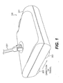
- FIG. 1 is a perspective view of a preferred embodiment of a cleaning apparatus according to the present invention.
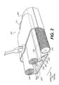
- FIG. 2 is a partial cut-away perspective view of the cleaning apparatus shown in FIG. 1 .
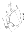
- FIGS. 3A and 3B are partial perspective views of alternate embodiments of the present invention.
- FIG. 4 is a partial cut-away assembly view of another embodiment of the present invention.
- FIG. 5 is a partial cut-away assembly view of yet another embodiment of the present invention.
- FIG. 6 is a partial cut-away assembly view of still another embodiment of the present invention.
- FIG. 7 is a partial cut-away assembly view of a further embodiment of the present invention.
- FIG. 8 is a partial cut-away assembly view of a still further embodiment of the present invention.
- FIG. 9 is a partial cut-away assembly view of an additional embodiment of the present invention.
- FIG. 10 is a partial cut-away assembly view of a further embodiment of the present invention.
- FIG. 11 is a partial cut-away assembly view of another embodiment of the present invention.
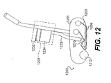
- FIG. 12 is a partial cut-away assembly view of yet another embodiment of the present invention.
- a cleaning apparatus for illustrative purposes, the preferred embodiments of a cleaning apparatus according to this invention are described in connection with the cleaning of floors. This invention, however, can be utilized in the cleaning of other surfaces, such as, for example, walls and sidewalks.
- FIG. 1 illustrates a preferred embodiment of a cleaning apparatus 100 according to the invention.
- a housing 201 is attached to a distal end of a handle 227.
- a plurality of wheels 202 rotatably mounted to the housing 201, allows for easy manipulation of the cleaning apparatus 100 along a surface to be cleaned.
- the cleaning apparatus 100 may be propelled autonomously (e.g., an extension of a robotic cleaning device wherein the robot is pre-programmed to direct itself over a surface to be cleaned), or be electrically self-propelled (e.g., a plug-in or battery operated unit wherein the apparatus advances without user assistance and the user merely walks behind the apparatus to direct the apparatus).
- a handle may not be necessary.
- FIG. 2 illustrates the internal components of the cleaning apparatus 100 shown in FIG. 1 .
- a cleaning ribbon 203 is dispensed from a supply reel 204 and is collected on a take-up reel 205. Both the supply reel 204 and the take-up reel 205 are rotatably mounted within the housing 201.
- a ribbon advancing reel 211 is directly coupled to the take-up reel 205, thus allowing a user to manually advance the cleaning ribbon 203 from the supply reel 204 whenever necessary.
- a guiding system 270 is mounted within the housing 201 to maintain proper orientation of the cleaning ribbon 203.
- the guiding system 270 consists of a plurality of rollers 207 and a platen 206.
- the plurality of rollers 207 and the platen 206 establish the path of the cleaning ribbon 203 between the supply reel 204 and the take-up reel 205, and create tension in the cleaning ribbon 203.
- the platen 206 also forms a cleaning surface 208 by maintaining a section of the cleaning ribbon 203 parallel to, and in substantial contact with, the surface to be cleaned.
- the path of the cleaning ribbon 203 and the tension in the cleaning ribbon 203 are established such that there is no lateral movement in the cleaning ribbon 203.
- the guiding system 270 is a track that engages the sides of the cleaning ribbon 203, and directs the cleaning ribbon 203 in a specified path.
- the guiding system 270 may not comprise the rollers 207 and would include only the tension in the cleaning ribbon 203 as established by either a platen 206, or the rotation of the supply reel 204 and take-up reel 205, or a combination thereof.
- the cleaning ribbon 203 is directed rearwardly, i.e., above the cleaning surface 208 in a direction opposite to the direction of normal travel of the cleaning apparatus 200 so as to create a particle trap 210.
- the particle trap 210 is created by the plurality of rollers 207, and an angled portion 209 formed on the forward edge of the platen 206.
- the angled portion 209 may extend from, or be mounted to, the stationary surface 206. In alternative embodiments, the angled surface could be separately mounted within the housing 201 or the angled portion 209 may not exist at all.
- a rotatable brush 212 At a location forward of the particle trap 210 is a rotatable brush 212.
- the rotatable brush 212 is rotatably mounted within the housing 201 and, in a preferred embodiment, is mounted on the same axis as one of the plurality of wheels 202 (shown in FIG. 1 ).
- the rotatable brush 212 is covered with a plurality of bristles and acts to propel larger particles from the surface to be cleaned into the particle trap 210.
- particles Once in the particle trap 210, particles are collected along with the spent cleaning ribbon 203 by the take-up reel 205.
- the take-up reel 205 collects the cleaning ribbon 203 so as to maintain a dirty side of the cleaning ribbon 203 facing the take-up reel 205.
- the rotatable brush of the present invention comprises a plurality of bristles
- the brush may include a plurality of flexible blades as shown, for example, in U.S. Patent No. 4,646,380 to Kobayashi, et al .
- the Kobayashi, et al. patent is hereinafter incorporated by reference.
- the cleaning ribbon 203 is preferably an electret material like that sold by S. C. Johnson & Son, Inc., of Racine, Wisconsin, under the trademark GRAB-ITTM. Additional compositions for the cleaning ribbon 203 could include an adhesive material, a fabric soaked in a cleaning agent, a textured cloth, or any combination thereof, for example.
- the cleaning ribbon 303 is packaged on the supply reel 304 in a manner that reduces the width of the supply reel 304, i.e., the cleaning ribbon 303 is folded at least once lengthwise before being wrapped on the supply reel 304.
- the guiding system 370 includes at least one track 371 formed to accept and substantially constrain at least one side edge of the cleaning ribbon 303 as the cleaning ribbon 303 is unwound.
- the at least one track 371 forms a contoured path that leads the cleaning ribbon 303 from a folded state to an unfolded state.
- FIG. 3B depicts an embodiment in which the cleaning ribbon 303 is folded at least once lengthwise before being collected, thereby reducing the width of the take-up reel 305.
- the guiding system 370 includes at least one track 371 formed to accept and substantially constrain at least one side edge of the cleaning ribbon 303.
- the at least one track 371 is contoured so as to force the constrained at least one side of the cleaning ribbon 303 over the cleaning surface of the cleaning ribbon 303, thereby folding the cleaning ribbon 303.
- the folded cleaning ribbon 303 can thus be collected by the take-up reel 305.
- FIGS. 4 , 5 , and 6 show other preferred embodiments of the invention.
- the cleaning apparatuses 400, 500, 600 shown in FIGS. 4 , 5 , and 6 are substantially the same as the embodiment discussed above, and similar parts have been given reference numerals that end in the same two digits.
- the primary distinction of these embodiments over the foregoing embodiment is that the means to drive the take-up reels 405, 505, 605, and thus advance the cleaning ribbons 403, 503, 603, differs for each.
- a ratchet mechanism 415 is employed for advancement of the cleaning ribbon 403.
- a foot pedal 416 By applying pressure to a foot pedal 416, a worm member 428 is moved rearwardly, thus rotating a take-up gear 417. Because the take-up gear 417 is attached to and is an extension of the take-up reel 405, the take-up reel 405 rotates, thus causing the cleaning ribbon 403 to advance.
- a further embodiment employs a belt 518 to drive the take-up reel 505.
- a take-up pulley 519 is attached to and is an extension of the take-up reel 505.
- a wheel pulley 520 is attached to and is an extension of one of the plurality of wheels 502. The belt 518 loops around the take-up pulley 519 and the wheel pulley 520.
- Advancing the cleaning apparatus 500 along the surface to be cleaned causes the plurality of wheels 502 to rotate. This simultaneously causes the wheel pulley 520 to rotate, and, as a result, the belt 518 drives the take-up pulley 519. As the take-up pulley 519 rotates, the take-up reel 505 does also, thus advancing the cleaning ribbon 503.
- cleaning potential for the cleaning ribbon 503 can be maximized by setting an optimal value for the rate at which the cleaning ribbon 503 advances with respect to the rate at which the cleaning apparatus 500 moves along the surface to be cleaned.
- FIG. 6 another embodiment utilizes gears to drive the take-up reel 605.
- a take-up gear 617 is attached to and is an extension of the take-up reel 605.
- a wheel gear 621 is attached to and is an extension of one of the plurality of wheels 602.
- additional gears 622 may be used to connect the wheel gear 621 and the take-up gear 617.
- Advancing the cleaning apparatus 600 along the surface to be cleaned causes the plurality of wheels 602 to rotate. This, in turn, causes the wheel gear 621 to rotate, and, as a result, driving power is transferred through the additional gears 622 to drive the take-up gear 617.
- the cleaning ribbon 603 is advanced.
- cleaning potential for the cleaning ribbon 603 can be maximized by setting an optimal value for the rate at which the cleaning ribbon 603 advances with respect to the rate at which the cleaning apparatus 600 moves along the surface to be cleaned.
- FIGS. 7 and 8 show other preferred embodiments of the invention.
- the cleaning apparatuses 700, 800 shown in FIGS. 7 and 8 are substantially the same as the embodiments discussed above, and similar parts have been given reference numerals that end in the same two digits.
- the primary distinction of these embodiments over the foregoing embodiments is that the means to drive the rotatable brushes 712, 812 differs for each.
- FIG. 7 an embodiment is depicted that uses a belt 718 to drive the rotatable brush 712.
- a brush pulley 723 is attached to and is an extension of the rotatable brush 712.
- a wheel pulley 720 is attached to and is an extension of one of the plurality of wheels 702. The belt 718 loops around the brush pulley 723 and the wheel pulley 720.
- Advancing the cleaning apparatus 700 along the surface to be cleaned causes the plurality of wheels 702 to rotate. This, in turn, causes the wheel pulley 720 to rotate, and, as a result, the belt 718 drives the brush pulley 723. As the brush pulley 723 rotates, the rotatable brush 712 does also.
- cleaning potential for the rotatable brush 712 can be maximized by setting an optimal value for the rate at which the rotatable brush 712 advances with respect to the rate at which the cleaning apparatus 700 moves along the surface to be cleaned.
- FIG. 8 a further embodiment is disclosed that uses gears to drive the rotatable brush 812.
- a wheel gear 821 is attached to and is an extension of one of the plurality of wheels 802.
- a brush gear 824 is attached to and is an extension of the rotatable brush 812.
- additional gears may be used to connect the wheel gear 821 and the brush gear 824.
- Advancing the cleaning apparatus 800 along the surface to be cleaned causes the plurality of wheels 802 to rotate. This, in turn, causes the wheel gear 821 to rotate, and, as a result, the brush gear 824 is driven.
- cleaning potential for the rotatable brush 812 can be maximized by setting an optimal value for the rate at which the rotatable brush 812 advances with respect to the rate at which the cleaning apparatus 800 moves along the surface to be cleaned.
- the cleaning apparatus of FIG. 8 could be configured such that the rotatable brush 812 always rotates in a direction to propel dust particles into the particle trap 810.
- the rotatable brush 812 could always rotate to propel dust particles into the particle trap, regardless of the direction of movement of the cleaning apparatus 800.
- FIGS. 9 and 10 illustrate still other preferred embodiments of the invention.
- the cleaning apparatuses 900, 1000 shown in FIGS. 9 and 10 are substantially the same as the embodiments discussed above, and similar parts have been given reference numerals that end in the same two digits.
- the primary distinction of these embodiments over the foregoing embodiments is that the supply reels 904, 1004, the take-up reels 905, 1005, the cleaning ribbons 903, 1003, and/or the rotatable brushes 912, 1012 are detachably secured.
- the housing 901 includes a detachably secured housing panel 913 and at least one mounting protrusion 941. Removal of the housing panel 913 exposes the at least one mounting protrusion 941 and allows for removal and replacement of a cartridge 914.
- the cartridge 914 comprises the supply reel 904, the take-up reel 905, the cleaning ribbon 903, which may be preformed to create a particle trap, the rotatable brush 912, and necessary means to detachably secure the cartridge 914 within the housing 901.
- This securement means may be embodied such that the cartridge 914 contains at least one aperture 942 for mating with the at least one mounting protrusion 941. As shown in FIG.
- the at least one aperture 942 may be formed through the rotational axis of either the supply reel 904, the take-up reel 905, the rotatable brush 912, or any combination therebetween.
- the mounted supply reel 904, take-up reel 905, or rotatable brush 912 may either rotate about the mounting protrusion 941 or the mounting protrusion 941 and the mounted supply reel 904, take-up reel 905, or rotatable brush 912 may rotate in unison (e.g., by forming the at least one mounting protrusion 941 and the at least one mounting aperture 942 with non-circular, identical cross sections).
- the securement means for the cartridge 914 includes any gearing or hardware that would mate with components within the housing 901 for driving the supply reel 904, the take-up reel 905, and/or the rotatable brush 912.
- a significant advantage of this embodiment is that the cleaning ribbon 903 and rotatable brush 912 can be used to their maximum cleaning potential and can then be easily replaced when necessary; the cleaning apparatus 900 need not be exchanged entirely. While in one embodiment of the invention the cartridge 914 is disposable, in another embodiment, the cartridge may be detached merely to facilitate replacement of the cleaning ribbon 903, or to allow for cleaning of the rotatable brush 912.
- the housing 1001 of FIG. 10 includes a detachably secured housing panel 1013. Removal of the housing panel 1013 allows for removal and replacement of either a reel cartridge 1025 comprising the supply reel 1004, the take-up reel 1005, the cleaning ribbon 1003, and the means necessary to detachably secure the reel cartridge 1025 within the housing 1001, or a brush cartridge 1026 comprising the rotatable brush 1012 and the necessary means to detachably secure the disposable brush cartridge 1026 within the housing 1001, or both the reel cartridge 1025 and the brush cartridge 1026.
- the cleaning ribbon may be preformed to create a particle trap.
- the securement means for the reel cartridge 1025 and the brush cartridge 1026 is substantially the same as that discussed for the cartridge 914 and will not be discussed further. Like the embodiment shown in FIG. 9 , this arrangement allows for maximization of cleaning potential. This embodiment, however, further allows the user to replace only the cleaning ribbon 1003 or only the rotatable brush 1012 in the instance that the two soil at different rates. Also similar to the embodiment of FIG. 9 , the reel cartridge 1025 and the brush cartridge 1026 may be disposable, or in a further embodiment, the reel cartridge 1025 and the brush cartridge 1026 may be removed to facilitate either replacement of the cleaning ribbon 1003 or cleaning of the rotatable brush 1012.
- FIG. 11 illustrates another embodiment of the invention.
- the cleaning apparatus 1100 shown in FIG. 11 is substantially the same as the embodiments discussed above, and similar parts have been given reference numerals that end in the same two digits.
- the primary distinction of this embodiment over the foregoing embodiments is that the platen 1106 is movable with respect to the housing 1101.
- the platen 1106 is held parallel to the surface to be cleaned by a linkage 1129.
- the platen 1106 may be moved with respect to the housing 1101 by a lever 1130 through the linkage 1129.
- the apparatus may be used on different surfaces (e.g., carpeting or rugs) and the cleaning ribbon 1103 may be more easily replaced.
- the manner shown in this embodiment is merely representative. A number of linkages or linkage-type devices could be used. Additionally, a number of means other than a hand-lever could be used to operate the linkage, including a foot-operated lever, or a motor, for example.
- the raising and lowering of the platen 1106 may be done automatically by the apparatus 1100.
- the apparatus 1100 By sensing the movement of the apparatus 1100 onto a new surface to be cleaned (e.g., movement from a hard floor to a carpet) the apparatus 1100 would automatically raise or lower the platen 1106 for uninterrupted cleaning on multiple surfaces.
- Such sensing of a new surface would be done, for example, by realizing a change in rolling resistance of the apparatus 1100 created by changing frictional characteristics of differing floor types.
- FIG. 12 shows a still further embodiment of the invention.
- the cleaning apparatus 1200 shown in FIG. 12 is substantially the same as the embodiments discussed above, and similar parts have been given reference numerals that end in the same two digits.
- the primary distinction of this embodiment over the foregoing embodiments is that suction is used in conjunction with the cleaning ribbon 1203 and the rotatable brush 1212.
- a vacuum unit 1231 includes a compressor 1232 for creating a low pressure suction, a length of vacuum tube 1233 extending from the compressor 1232 to within the housing 1201 for aiding in debris collection, and a debris container 1234 for containing debris collected by the vacuum tube 1233.
- the vacuum unit 1231 removes debris directly from the particle trap 1210.
- the suction can be applied to the portion of the cleaning ribbon 1203 that creates the cleaning surface 1208 on a side of the cleaning ribbon 1203 opposite the surface to be cleaned. In this way, the cleaning ribbon's 1203 ability to retain particles is enhanced.
- the suction can be applied to the portion of cleaning ribbon 1203 that forms the particle trap 1210 on a side of the cleaning ribbon 1203 opposite the side of the cleaning ribbon 1203 that retains foreign particles. By so doing, retention of foreign particles within the particle trap 1210 is enhanced.
- the apparatus of this invention is suited for use in cleaning floors, and is particularly useful for household use on hard-surfaced floors.
- the cleaning ribbon disposed parallel to, and in substantial contact with, the floor is effective at attracting and retaining smaller debris particles.
- the rotatable brush acts to sweep larger debris particles into a particle trap. By collecting smaller and larger debris particles, the apparatus effectively cleans an entire surface with minimal manual interaction.
Landscapes
- Nozzles For Electric Vacuum Cleaners (AREA)
- Cleaning Implements For Floors, Carpets, Furniture, Walls, And The Like (AREA)
- Manufacturing Of Electric Cables (AREA)
- Body Washing Hand Wipes And Brushes (AREA)
Abstract
Description
- This invention relates generally to a cleaning apparatus, and, in particular, to an apparatus especially suited for cleaning hard-surfaced floors. Furthermore, it relates to a cartridge for detachable securement within a cleaning apparatus.
- Cleaning floors is a tedious and laborious task. Over the years, many devices have been designed for this purpose, including brooms, mops, vacuum-cleaners, and countless variations thereon. For example,
U.S. Patent Nos. 5,896,611 and500,976 each discloses a device that utilizes a rotatable brush to accelerate debris into a collection container. These devices have the ability to pick up relatively large dirt particles, but smaller items such as dust and hair are usually left behind. Additionally, these devices generally are designed for industrial applications, and therefore, tend to be too cumbersome for household use. - Meanwhile, widely-used electret cloth mops, which utilize static electricity to attract dirt, hair, and dust particles, pose the opposite problem. These devices are effective at picking up small particles, but larger debris tends to collect at the front edge of the mop where the debris is pushed across the floor until a user manually removes the debris from the floor. In addition, using electret cloth mops is time consuming because the user frequently has to replace spent electret cloth. Other floor cleaning devices, like those depicted in
U.S. Patents Nos. 5,092,699 and5,372,609 , attempt to solve this problem by providing a continually-fed cleaning cloth, but these devices are likewise incapable of picking up larger debris.
A cleaning apparatus according to the preamble ofclaim 1 is disclosed inUS 2,601,537 . - Accordingly, there is a need in the art for a cleaning apparatus that is capable of removing both large and small particles from a surface, yet is easily handled and operated.
- This invention addresses the foregoing needs in the art by providing a cleaning apparatus with continuous action wiping and sweeping, in which a continuously-fed cleaning ribbon works in conjunction with a rotatable sweeping brush to remove both large and small debris from a hard-surfaced floor.
- In a first aspect of the invention, the cleaning apparatus includes a housing and a handle attached to the housing. The housing houses a supply reel, a take-up reel, a cleaning ribbon extending between the supply reel and the take-up reel, and a rotatable brush. The cleaning ribbon is configured to form a particle trap, and the rotatable brush sweeps particles into the particle trap from a forward side of the particle trap.
- In another aspect of the invention, a cleaning apparatus includes a housing and a handle attached to the housing. The housing detachably secures a cartridge. The cartridge includes the supply reel, the take-up reel, the cleaning ribbon extending between the supply reel and the take-up reel, and the rotatable brush.
- In a further aspect of the invention, a cartridge for detachable securement within a cleaning apparatus includes a supply reel, a take-up reel, and a cleaning ribbon extending between the supply reel and the take-up reel configured to create a particle trap. The cartridge further includes means for sweeping particles into a particle trap, and means for detachably securing the cartridge to the cleaning apparatus.
- A better understanding of these and other objects, features, and advantages of the invention may be had by reference to the drawings and to the accompanying description, in which there are illustrated and described preferred embodiments of the invention.
-
FIG. 1 is a perspective view of a preferred embodiment of a cleaning apparatus according to the present invention. -
FIG. 2 is a partial cut-away perspective view of the cleaning apparatus shown inFIG. 1 . -
FIGS. 3A and3B are partial perspective views of alternate embodiments of the present invention. -
FIG. 4 is a partial cut-away assembly view of another embodiment of the present invention. -
FIG. 5 is a partial cut-away assembly view of yet another embodiment of the present invention. -
FIG. 6 is a partial cut-away assembly view of still another embodiment of the present invention. -
FIG. 7 is a partial cut-away assembly view of a further embodiment of the present invention. -
FIG. 8 is a partial cut-away assembly view of a still further embodiment of the present invention. -
FIG. 9 is a partial cut-away assembly view of an additional embodiment of the present invention. -
FIG. 10 is a partial cut-away assembly view of a further embodiment of the present invention. -
FIG. 11 is a partial cut-away assembly view of another embodiment of the present invention. -
FIG. 12 is a partial cut-away assembly view of yet another embodiment of the present invention. - For illustrative purposes, the preferred embodiments of a cleaning apparatus according to this invention are described in connection with the cleaning of floors. This invention, however, can be utilized in the cleaning of other surfaces, such as, for example, walls and sidewalks.
-
FIG. 1 illustrates a preferred embodiment of acleaning apparatus 100 according to the invention. Ahousing 201 is attached to a distal end of ahandle 227. A plurality ofwheels 202, rotatably mounted to thehousing 201, allows for easy manipulation of thecleaning apparatus 100 along a surface to be cleaned. In other embodiments, for example, thecleaning apparatus 100 may be propelled autonomously (e.g., an extension of a robotic cleaning device wherein the robot is pre-programmed to direct itself over a surface to be cleaned), or be electrically self-propelled (e.g., a plug-in or battery operated unit wherein the apparatus advances without user assistance and the user merely walks behind the apparatus to direct the apparatus). For these alternate embodiments, a handle may not be necessary. -
FIG. 2 illustrates the internal components of thecleaning apparatus 100 shown inFIG. 1 . Acleaning ribbon 203 is dispensed from asupply reel 204 and is collected on a take-up reel 205. Both thesupply reel 204 and the take-up reel 205 are rotatably mounted within thehousing 201. In the present embodiment, aribbon advancing reel 211 is directly coupled to the take-up reel 205, thus allowing a user to manually advance thecleaning ribbon 203 from thesupply reel 204 whenever necessary. - A guiding
system 270 is mounted within thehousing 201 to maintain proper orientation of thecleaning ribbon 203. In this embodiment, the guidingsystem 270 consists of a plurality ofrollers 207 and aplaten 206. The plurality ofrollers 207 and theplaten 206 establish the path of thecleaning ribbon 203 between thesupply reel 204 and the take-up reel 205, and create tension in thecleaning ribbon 203. Theplaten 206 also forms acleaning surface 208 by maintaining a section of thecleaning ribbon 203 parallel to, and in substantial contact with, the surface to be cleaned. The path of thecleaning ribbon 203 and the tension in thecleaning ribbon 203 are established such that there is no lateral movement in thecleaning ribbon 203. - In an alternative embodiment, the guiding
system 270 is a track that engages the sides of thecleaning ribbon 203, and directs thecleaning ribbon 203 in a specified path. In a further embodiment, the guidingsystem 270 may not comprise therollers 207 and would include only the tension in thecleaning ribbon 203 as established by either aplaten 206, or the rotation of thesupply reel 204 and take-up reel 205, or a combination thereof. - At the forward edge of the
cleaning surface 208, thecleaning ribbon 203 is directed rearwardly, i.e., above thecleaning surface 208 in a direction opposite to the direction of normal travel of thecleaning apparatus 200 so as to create aparticle trap 210. In this embodiment, theparticle trap 210 is created by the plurality ofrollers 207, and anangled portion 209 formed on the forward edge of theplaten 206. Theangled portion 209 may extend from, or be mounted to, thestationary surface 206. In alternative embodiments, the angled surface could be separately mounted within thehousing 201 or theangled portion 209 may not exist at all. - At a location forward of the
particle trap 210 is arotatable brush 212. Therotatable brush 212 is rotatably mounted within thehousing 201 and, in a preferred embodiment, is mounted on the same axis as one of the plurality of wheels 202 (shown inFIG. 1 ). Therotatable brush 212 is covered with a plurality of bristles and acts to propel larger particles from the surface to be cleaned into theparticle trap 210. Once in theparticle trap 210, particles are collected along with the spent cleaningribbon 203 by the take-upreel 205. The take-upreel 205 collects the cleaningribbon 203 so as to maintain a dirty side of thecleaning ribbon 203 facing the take-upreel 205. - While the rotatable brush of the present invention comprises a plurality of bristles, in alternative embodiments, the brush may include a plurality of flexible blades as shown, for example, in
U.S. Patent No. 4,646,380 to Kobayashi, et al . The Kobayashi, et al. patent is hereinafter incorporated by reference. The cleaningribbon 203 is preferably an electret material like that sold by S. C. Johnson & Son, Inc., of Racine, Wisconsin, under the trademark GRAB-IT™. Additional compositions for thecleaning ribbon 203 could include an adhesive material, a fabric soaked in a cleaning agent, a textured cloth, or any combination thereof, for example. - In the further embodiment depicted in
FIG. 3A , the cleaningribbon 303 is packaged on thesupply reel 304 in a manner that reduces the width of thesupply reel 304, i.e., the cleaningribbon 303 is folded at least once lengthwise before being wrapped on thesupply reel 304. In such an embodiment, the guidingsystem 370 includes at least onetrack 371 formed to accept and substantially constrain at least one side edge of thecleaning ribbon 303 as the cleaningribbon 303 is unwound. The at least onetrack 371 forms a contoured path that leads thecleaning ribbon 303 from a folded state to an unfolded state. - Similarly,
FIG. 3B depicts an embodiment in which thecleaning ribbon 303 is folded at least once lengthwise before being collected, thereby reducing the width of the take-upreel 305. Like the embodiment ofFIG. 3A , the guidingsystem 370 includes at least onetrack 371 formed to accept and substantially constrain at least one side edge of thecleaning ribbon 303. The at least onetrack 371 is contoured so as to force the constrained at least one side of thecleaning ribbon 303 over the cleaning surface of thecleaning ribbon 303, thereby folding thecleaning ribbon 303. The foldedcleaning ribbon 303 can thus be collected by the take-upreel 305. -
FIGS. 4 ,5 , and6 show other preferred embodiments of the invention. The cleaningapparatuses FIGS. 4 ,5 , and6 are substantially the same as the embodiment discussed above, and similar parts have been given reference numerals that end in the same two digits. The primary distinction of these embodiments over the foregoing embodiment is that the means to drive the take-upreels ribbons - In
FIG. 4 , aratchet mechanism 415 is employed for advancement of thecleaning ribbon 403. By applying pressure to afoot pedal 416, aworm member 428 is moved rearwardly, thus rotating a take-upgear 417. Because the take-upgear 417 is attached to and is an extension of the take-upreel 405, the take-upreel 405 rotates, thus causing thecleaning ribbon 403 to advance. - In
FIG. 5 , a further embodiment employs abelt 518 to drive the take-upreel 505. A take-uppulley 519 is attached to and is an extension of the take-upreel 505. Awheel pulley 520 is attached to and is an extension of one of the plurality ofwheels 502. Thebelt 518 loops around the take-uppulley 519 and thewheel pulley 520. - Advancing the
cleaning apparatus 500 along the surface to be cleaned causes the plurality ofwheels 502 to rotate. This simultaneously causes thewheel pulley 520 to rotate, and, as a result, thebelt 518 drives the take-uppulley 519. As the take-uppulley 519 rotates, the take-upreel 505 does also, thus advancing the cleaningribbon 503. By varying the sizes of thewheel pulley 520 and the take-uppulley 519, cleaning potential for thecleaning ribbon 503 can be maximized by setting an optimal value for the rate at which thecleaning ribbon 503 advances with respect to the rate at which thecleaning apparatus 500 moves along the surface to be cleaned. - In
FIG. 6 , another embodiment utilizes gears to drive the take-upreel 605. A take-upgear 617 is attached to and is an extension of the take-upreel 605. Awheel gear 621 is attached to and is an extension of one of the plurality ofwheels 602. As necessary,additional gears 622 may be used to connect thewheel gear 621 and the take-upgear 617. - Advancing the
cleaning apparatus 600 along the surface to be cleaned causes the plurality ofwheels 602 to rotate. This, in turn, causes thewheel gear 621 to rotate, and, as a result, driving power is transferred through theadditional gears 622 to drive the take-upgear 617. Thus, the cleaning ribbon 603 is advanced. By varying the sizes of thewheel gear 621, the take-upgear 617, and theadditional gears 622, cleaning potential for the cleaning ribbon 603 can be maximized by setting an optimal value for the rate at which the cleaning ribbon 603 advances with respect to the rate at which thecleaning apparatus 600 moves along the surface to be cleaned. -
FIGS. 7 and8 show other preferred embodiments of the invention. The cleaningapparatuses FIGS. 7 and8 are substantially the same as the embodiments discussed above, and similar parts have been given reference numerals that end in the same two digits. The primary distinction of these embodiments over the foregoing embodiments is that the means to drive the rotatable brushes 712, 812 differs for each. - In
FIG. 7 , an embodiment is depicted that uses abelt 718 to drive therotatable brush 712. Abrush pulley 723 is attached to and is an extension of therotatable brush 712. Awheel pulley 720 is attached to and is an extension of one of the plurality ofwheels 702. Thebelt 718 loops around thebrush pulley 723 and thewheel pulley 720. - Advancing the
cleaning apparatus 700 along the surface to be cleaned causes the plurality ofwheels 702 to rotate. This, in turn, causes thewheel pulley 720 to rotate, and, as a result, thebelt 718 drives thebrush pulley 723. As thebrush pulley 723 rotates, therotatable brush 712 does also. By varying the sizes of thewheel pulley 720 and thebrush pulley 723, cleaning potential for therotatable brush 712 can be maximized by setting an optimal value for the rate at which therotatable brush 712 advances with respect to the rate at which thecleaning apparatus 700 moves along the surface to be cleaned. - In
FIG. 8 , a further embodiment is disclosed that uses gears to drive therotatable brush 812. Awheel gear 821 is attached to and is an extension of one of the plurality ofwheels 802. Abrush gear 824 is attached to and is an extension of therotatable brush 812. As necessary, additional gears (not shown) may be used to connect thewheel gear 821 and thebrush gear 824. - Advancing the
cleaning apparatus 800 along the surface to be cleaned causes the plurality ofwheels 802 to rotate. This, in turn, causes thewheel gear 821 to rotate, and, as a result, thebrush gear 824 is driven. By varying the sizes of thewheel gear 821 and thebrush gear 824, cleaning potential for therotatable brush 812 can be maximized by setting an optimal value for the rate at which therotatable brush 812 advances with respect to the rate at which thecleaning apparatus 800 moves along the surface to be cleaned. Alternatively, the cleaning apparatus ofFIG. 8 could be configured such that therotatable brush 812 always rotates in a direction to propel dust particles into the particle trap 810. By employing, for example, a clutch in conjunction with the gearing, therotatable brush 812 could always rotate to propel dust particles into the particle trap, regardless of the direction of movement of thecleaning apparatus 800. -
FIGS. 9 and10 illustrate still other preferred embodiments of the invention. The cleaningapparatuses FIGS. 9 and10 are substantially the same as the embodiments discussed above, and similar parts have been given reference numerals that end in the same two digits. The primary distinction of these embodiments over the foregoing embodiments is that thesupply reels reels ribbons - According to the embodiment of
FIG. 9 , thehousing 901 includes a detachablysecured housing panel 913 and at least one mountingprotrusion 941. Removal of thehousing panel 913 exposes the at least one mountingprotrusion 941 and allows for removal and replacement of acartridge 914. Thecartridge 914 comprises thesupply reel 904, the take-upreel 905, the cleaningribbon 903, which may be preformed to create a particle trap, therotatable brush 912, and necessary means to detachably secure thecartridge 914 within thehousing 901. This securement means may be embodied such that thecartridge 914 contains at least oneaperture 942 for mating with the at least one mountingprotrusion 941. As shown inFIG. 9 , the at least oneaperture 942 may be formed through the rotational axis of either thesupply reel 904, the take-upreel 905, therotatable brush 912, or any combination therebetween. In this embodiment, the mountedsupply reel 904, take-upreel 905, orrotatable brush 912 may either rotate about the mountingprotrusion 941 or the mountingprotrusion 941 and the mountedsupply reel 904, take-upreel 905, orrotatable brush 912 may rotate in unison (e.g., by forming the at least one mountingprotrusion 941 and the at least one mountingaperture 942 with non-circular, identical cross sections). Additionally, in other embodiments, the securement means for thecartridge 914 includes any gearing or hardware that would mate with components within thehousing 901 for driving thesupply reel 904, the take-upreel 905, and/or therotatable brush 912. - A significant advantage of this embodiment is that the cleaning
ribbon 903 androtatable brush 912 can be used to their maximum cleaning potential and can then be easily replaced when necessary; thecleaning apparatus 900 need not be exchanged entirely. While in one embodiment of the invention thecartridge 914 is disposable, in another embodiment, the cartridge may be detached merely to facilitate replacement of thecleaning ribbon 903, or to allow for cleaning of therotatable brush 912. - Similar to the
housing 901 ofFIG. 9 , thehousing 1001 ofFIG. 10 includes a detachablysecured housing panel 1013. Removal of thehousing panel 1013 allows for removal and replacement of either areel cartridge 1025 comprising thesupply reel 1004, the take-up reel 1005, thecleaning ribbon 1003, and the means necessary to detachably secure thereel cartridge 1025 within thehousing 1001, or abrush cartridge 1026 comprising therotatable brush 1012 and the necessary means to detachably secure thedisposable brush cartridge 1026 within thehousing 1001, or both thereel cartridge 1025 and thebrush cartridge 1026. For thereel cartridge 1025, the cleaning ribbon may be preformed to create a particle trap. The securement means for thereel cartridge 1025 and thebrush cartridge 1026 is substantially the same as that discussed for thecartridge 914 and will not be discussed further. Like the embodiment shown inFIG. 9 , this arrangement allows for maximization of cleaning potential. This embodiment, however, further allows the user to replace only thecleaning ribbon 1003 or only therotatable brush 1012 in the instance that the two soil at different rates. Also similar to the embodiment ofFIG. 9 , thereel cartridge 1025 and thebrush cartridge 1026 may be disposable, or in a further embodiment, thereel cartridge 1025 and thebrush cartridge 1026 may be removed to facilitate either replacement of thecleaning ribbon 1003 or cleaning of therotatable brush 1012. -
FIG. 11 illustrates another embodiment of the invention. Thecleaning apparatus 1100 shown inFIG. 11 is substantially the same as the embodiments discussed above, and similar parts have been given reference numerals that end in the same two digits. The primary distinction of this embodiment over the foregoing embodiments is that theplaten 1106 is movable with respect to thehousing 1101. - According to the embodiment of
FIG. 11 , theplaten 1106 is held parallel to the surface to be cleaned by alinkage 1129. Theplaten 1106 may be moved with respect to thehousing 1101 by alever 1130 through thelinkage 1129. By moving thestationary surface 1106, the apparatus may be used on different surfaces (e.g., carpeting or rugs) and thecleaning ribbon 1103 may be more easily replaced. The manner shown in this embodiment is merely representative. A number of linkages or linkage-type devices could be used. Additionally, a number of means other than a hand-lever could be used to operate the linkage, including a foot-operated lever, or a motor, for example. If a motor is used, the raising and lowering of theplaten 1106 may be done automatically by theapparatus 1100. By sensing the movement of theapparatus 1100 onto a new surface to be cleaned (e.g., movement from a hard floor to a carpet) theapparatus 1100 would automatically raise or lower theplaten 1106 for uninterrupted cleaning on multiple surfaces. Such sensing of a new surface would be done, for example, by realizing a change in rolling resistance of theapparatus 1100 created by changing frictional characteristics of differing floor types. -
FIG. 12 shows a still further embodiment of the invention. Thecleaning apparatus 1200 shown inFIG. 12 is substantially the same as the embodiments discussed above, and similar parts have been given reference numerals that end in the same two digits. The primary distinction of this embodiment over the foregoing embodiments is that suction is used in conjunction with thecleaning ribbon 1203 and therotatable brush 1212. - According to
FIG. 12 , avacuum unit 1231 includes acompressor 1232 for creating a low pressure suction, a length ofvacuum tube 1233 extending from thecompressor 1232 to within thehousing 1201 for aiding in debris collection, and adebris container 1234 for containing debris collected by thevacuum tube 1233. In one embodiment, thevacuum unit 1231 removes debris directly from theparticle trap 1210. Alternatively, the suction can be applied to the portion of thecleaning ribbon 1203 that creates thecleaning surface 1208 on a side of thecleaning ribbon 1203 opposite the surface to be cleaned. In this way, the cleaning ribbon's 1203 ability to retain particles is enhanced. As a further variation of this embodiment, the suction can be applied to the portion ofcleaning ribbon 1203 that forms theparticle trap 1210 on a side of thecleaning ribbon 1203 opposite the side of thecleaning ribbon 1203 that retains foreign particles. By so doing, retention of foreign particles within theparticle trap 1210 is enhanced. - The embodiments discussed above are representative of embodiments of the present invention and are provided for illustrative purposes only. They are not intended to limit the scope of the invention. Variations and modifications are apparent from a reading of the preceding description and are included within the scope of the invention. The invention is intended to be limited only by the scope of the accompanying claims.
- The apparatus of this invention is suited for use in cleaning floors, and is particularly useful for household use on hard-surfaced floors. The cleaning ribbon disposed parallel to, and in substantial contact with, the floor is effective at attracting and retaining smaller debris particles. As the apparatus is moved along the surface to be cleaned, the rotatable brush acts to sweep larger debris particles into a particle trap. By collecting smaller and larger debris particles, the apparatus effectively cleans an entire surface with minimal manual interaction.
Claims (19)
- A cleaning apparatus (100), comprising:a housing (201);a supply reel (204) secured within the housing (201);a take-up reel (205) secured within the housing (201);a cleaning ribbon (203) extending from the supply reel (204) to the take-up reel (205); the apparatus being characterised bya rotatable brush (212) secured within the housing,wherein a particle trap (210) is formed by a configuration of the cleaning ribbon (203), and the rotatable brush (212) is disposed on a forward side of the particle trap (210), and sweeps debris into the particle trap (210) upon rotation of the rotatable brush (212).
- A cleaning apparatus according to claim 1, further comprising a handle attached to the housing for manually moving the apparatus along a surface to be cleaned.
- A cleaning apparatus, according to claim 1 including:a cartridge (914) detachably secured within the housing (901), the cartridge including:the supply reel (904);the take-up reel (905);the cleaning ribbon (903) the cleaning ribbon (903) having a cleaning surface positionable substantially parallel to a surface to be cleaned; andthe rotatable brush (912).
- A cleaning apparatus according to claim 3, wherein the housing (901) includes a panel (913) that is removable for providing access to the cartridge.
- A cleaning apparatus according to claim 3, wherein the cleaning ribbon (903) is comprised of an electret material that electrostatically attracts and retains debris.
- A cleaning apparatus according to claim 3, wherein the cleaning ribbon is comprised of an adhesive material.
- A cleaning apparatus according to claim 3, wherein the cleaning ribbon is saturated with a cleaning agent.
- A cleaning apparatus according to claim 3, wherein the cleaning ribbon is a textured cloth.
- A cleaning apparatus according to claim 3, wherein the cleaning ribbon comprises a combination of at least two of an electret material, an adhesive material, a material saturated with a cleaning agent, and a textured cloth.
- A cleaning apparatus according to claim 3, wherein the cleaning ribbon (303) is wound on the supply reel (304) in such a way that the width of the supply reel (304) is reduced.
- A cartridge (914) for detachable securement within a cleaning apparatus (900), the cartridge (914) comprising:a supply reel (904);a take-up reel (905);a cleaning ribbon (903) extending between the supply reel (904) and the take-up reel (905), the cleaning ribbon (903) being configured so as to form a particle trap;means (912) for sweeping debris into the particle trap; andmeans (941, 913) for detachably securing the cartridge (914) to the cleaning apparatus (900).
- A cartridge according to claim 11, wherein the cleaning ribbon is configured to form a particle trap.
- A cartridge according to claim 11, wherein the sweeping means comprises a rotatable brush.
- A cartridge according to claim 11, wherein the sweeping means comprises a plurality of rotating brushes.
- A cartridge according to claim 11, wherein the securing means consists of at least one aperture within the cartridge for mating with at least one protrusion within the cleaning apparatus.
- A cartridge according to claim 15, wherein the at least one aperture rotates freely about the at least one protrusion.
- A cartridge according to claim 15, wherein the at least one aperture rotates in unison with the at least one protrusion.
- A cartridge according to claim 11, wherein the cleaning ribbon is wound on the supply reel for reducing the width of the supply reel.
- A cartridge according to claim 11, wherein the cleaning ribbon is collected by the take-up reel for reducing the width of the take-up reel.
Applications Claiming Priority (3)
| Application Number | Priority Date | Filing Date | Title |
|---|---|---|---|
| US10/079,843 US6859976B2 (en) | 2002-02-22 | 2002-02-22 | Cleaning apparatus with continuous action wiping and sweeping |
| US79843 | 2002-02-22 | ||
| PCT/US2003/005069 WO2003071916A1 (en) | 2002-02-22 | 2003-02-21 | Cleaning apparatus with continuous action wiping and sweeping |
Publications (2)
| Publication Number | Publication Date |
|---|---|
| EP1476065A1 EP1476065A1 (en) | 2004-11-17 |
| EP1476065B1 true EP1476065B1 (en) | 2010-04-07 |
Family
ID=27752783
Family Applications (1)
| Application Number | Title | Priority Date | Filing Date |
|---|---|---|---|
| EP03711150A Expired - Lifetime EP1476065B1 (en) | 2002-02-22 | 2003-02-21 | Cleaning apparatus with continuous action wiping and sweeping |
Country Status (8)
| Country | Link |
|---|---|
| US (1) | US6859976B2 (en) |
| EP (1) | EP1476065B1 (en) |
| JP (1) | JP2005518235A (en) |
| AT (1) | ATE463195T1 (en) |
| AU (1) | AU2003215329A1 (en) |
| DE (1) | DE60332006D1 (en) |
| TW (1) | TWI236361B (en) |
| WO (1) | WO2003071916A1 (en) |
Cited By (1)
| Publication number | Priority date | Publication date | Assignee | Title |
|---|---|---|---|---|
| CN112274062A (en) * | 2020-09-21 | 2021-01-29 | 罗国海 | Cleaning device for cleaning burnt stone tabletop or gap |
Families Citing this family (74)
| Publication number | Priority date | Publication date | Assignee | Title |
|---|---|---|---|---|
| US7013528B2 (en) * | 2002-01-28 | 2006-03-21 | Bissell Homecare, Inc. | Floor cleaner with dusting |
| US7225503B1 (en) * | 2002-11-27 | 2007-06-05 | Bissell Homecare, Inc. | Hand-held deep cleaner |
| US6966098B2 (en) * | 2003-02-27 | 2005-11-22 | Matsushita Electric Industrial Co., Ltd. | Cleaner |
| AU2005212284A1 (en) * | 2004-02-04 | 2005-08-25 | S. C. Johnson & Son, Inc. | Surface treating device with cartridge-based cleaning system |
| US7223036B2 (en) * | 2004-03-05 | 2007-05-29 | Long Chang | Auto loading and auto dampening cleaning apparatus |
| CA2588870A1 (en) * | 2004-11-23 | 2006-06-01 | S. C. Johnson & Son, Inc. | Device and methods of providing air purification in combination with cleaning of surfaces |
| US7891898B2 (en) | 2005-01-28 | 2011-02-22 | S.C. Johnson & Son, Inc. | Cleaning pad for wet, damp or dry cleaning |
| US7976235B2 (en) | 2005-01-28 | 2011-07-12 | S.C. Johnson & Son, Inc. | Cleaning kit including duster and spray |
| US7740412B2 (en) | 2005-01-28 | 2010-06-22 | S.C. Johnson & Son, Inc. | Method of cleaning using a device with a liquid reservoir and replaceable non-woven pad |
| AU2006287920B2 (en) | 2005-04-15 | 2012-02-02 | S. C. Johnson & Son, Inc. | Continuous adhesive twin roller cleaning device |
| US7578020B2 (en) * | 2005-06-28 | 2009-08-25 | S.C. Johnson & Son, Inc. | Surface treating device with top load cartridge-based cleaning system |
| US20070006404A1 (en) * | 2005-07-08 | 2007-01-11 | Gooten Innolife Corporation | Remote control sweeper |
| ITMI20052214A1 (en) * | 2005-11-18 | 2007-05-19 | Elwatt Srl | BRUSH FOR CLEANING SURFACES |
| DE102007002936A1 (en) * | 2007-01-19 | 2008-07-24 | BSH Bosch und Siemens Hausgeräte GmbH | Cleaning device for preferably flat surfaces |
| DE102007002938A1 (en) * | 2007-01-19 | 2008-07-24 | BSH Bosch und Siemens Hausgeräte GmbH | Cleaning device for preferably flat surfaces |
| US8893347B2 (en) | 2007-02-06 | 2014-11-25 | S.C. Johnson & Son, Inc. | Cleaning or dusting pad with attachment member holder |
| KR100990781B1 (en) * | 2007-02-09 | 2010-10-29 | 산요덴키가부시키가이샤 | Electric vacuum cleaner |
| US20090097902A1 (en) * | 2007-10-16 | 2009-04-16 | Richard Lemmon | Cleaning device |
| US8672799B2 (en) * | 2008-10-12 | 2014-03-18 | Christopher C. Sappenfield | Rotary units, rotary mechanisms, and related applications |
| US8662781B2 (en) * | 2010-03-26 | 2014-03-04 | Christopher C. Sappenfield | Cleaning implements, cleaning material components, and related methods |
| US9382973B2 (en) | 2008-10-12 | 2016-07-05 | Christopher C. Sappenfield | Rotary units, rotary mechanisms, and related applications |
| US9312740B2 (en) | 2008-10-12 | 2016-04-12 | Christopher C. Sappenfield | Apparatus comprising counter-rotational mechanisms and related methods to convey current |
| US8774970B2 (en) | 2009-06-11 | 2014-07-08 | S.C. Johnson & Son, Inc. | Trainable multi-mode floor cleaning device |
| US8578564B2 (en) | 2009-11-05 | 2013-11-12 | The Procter & Gamble Company | Handle for removable cleaning implement |
| US8468635B2 (en) * | 2009-11-25 | 2013-06-25 | Church & Dwight Co., Inc. | Surface treating device |
| US20110146011A1 (en) * | 2009-12-18 | 2011-06-23 | Todd Mitchell Day | Apparatus for collecting debris from a target surface |
| DE102010018010A1 (en) * | 2010-04-23 | 2011-10-27 | Anton Jäger | cleaning device |
| US8984697B2 (en) | 2011-06-01 | 2015-03-24 | S.C. Johnson & Son, Inc. | Quick pickup device for debris on any surface with positive capture |
| ITMO20110240A1 (en) * | 2011-09-22 | 2013-03-23 | Francesco Accorsi | CLEANING DEVICE, PARTICULARLY FOR FLOORS AND FLAT SURFACES |
| US9119463B2 (en) | 2011-10-03 | 2015-09-01 | Pentair Water Pool & Spa, Inc. | Pool cleaner with detachable scrubber assembly |
| TWI485011B (en) * | 2012-03-02 | 2015-05-21 | Univ Shu Te | Cleaning device |
| WO2014033055A1 (en) | 2012-08-27 | 2014-03-06 | Aktiebolaget Electrolux | Robot positioning system |
| US9420932B2 (en) | 2012-09-17 | 2016-08-23 | Bissell Homecare, Inc. | Steam mop with grout cleaning tool and method |
| CN104797185B (en) * | 2012-10-10 | 2017-06-20 | 金井利美男 | Roll banding formula sweeping tool |
| CN110448222A (en) | 2013-04-15 | 2019-11-15 | 伊莱克斯公司 | Robotic vacuum cleaner |
| JP6198234B2 (en) | 2013-04-15 | 2017-09-20 | アクティエボラゲット エレクトロラックス | Robot vacuum cleaner with protruding side brush |
| WO2015090399A1 (en) | 2013-12-19 | 2015-06-25 | Aktiebolaget Electrolux | Robotic cleaning device and method for landmark recognition |
| US10209080B2 (en) | 2013-12-19 | 2019-02-19 | Aktiebolaget Electrolux | Robotic cleaning device |
| WO2015090398A1 (en) | 2013-12-19 | 2015-06-25 | Aktiebolaget Electrolux | Robotic vacuum cleaner with side brush moving in spiral pattern |
| CN105744872B (en) | 2013-12-19 | 2020-01-14 | 伊莱克斯公司 | Adaptive speed control of rotating side brushes |
| WO2015090405A1 (en) | 2013-12-19 | 2015-06-25 | Aktiebolaget Electrolux | Sensing climb of obstacle of a robotic cleaning device |
| WO2015090404A1 (en) | 2013-12-19 | 2015-06-25 | Aktiebolaget Electrolux | Prioritizing cleaning areas |
| US9811089B2 (en) | 2013-12-19 | 2017-11-07 | Aktiebolaget Electrolux | Robotic cleaning device with perimeter recording function |
| US10231591B2 (en) | 2013-12-20 | 2019-03-19 | Aktiebolaget Electrolux | Dust container |
| KR102325130B1 (en) | 2014-07-10 | 2021-11-12 | 에이비 엘렉트로룩스 | Method for detecting a measurement error in a robotic cleaning device |
| EP3190939B1 (en) | 2014-09-08 | 2021-07-21 | Aktiebolaget Electrolux | Robotic vacuum cleaner |
| KR102271782B1 (en) | 2014-09-08 | 2021-06-30 | 에이비 엘렉트로룩스 | Robotic vacuum cleaner |
| WO2016053221A1 (en) * | 2014-09-29 | 2016-04-07 | Yapim Elektrik San. Ve Tic. A.S. | Automatic hard floor cleaning head |
| EP3230814B1 (en) | 2014-12-10 | 2021-02-17 | Aktiebolaget Electrolux | Using laser sensor for floor type detection |
| EP3229983B1 (en) | 2014-12-12 | 2019-02-20 | Aktiebolaget Electrolux | Side brush and robotic cleaner |
| US10678251B2 (en) | 2014-12-16 | 2020-06-09 | Aktiebolaget Electrolux | Cleaning method for a robotic cleaning device |
| EP3234714B1 (en) | 2014-12-16 | 2021-05-12 | Aktiebolaget Electrolux | Experience-based roadmap for a robotic cleaning device |
| KR102343513B1 (en) | 2015-04-17 | 2021-12-28 | 에이비 엘렉트로룩스 | Robot cleaning device and control method of robot cleaning device |
| KR102445064B1 (en) | 2015-09-03 | 2022-09-19 | 에이비 엘렉트로룩스 | system of robot cleaning device |
| WO2017153598A1 (en) * | 2016-03-11 | 2017-09-14 | 1A Dienstleistungs, Handels und Service GmbH | New cleaning device and method for cleaning |
| CN108603935A (en) | 2016-03-15 | 2018-09-28 | 伊莱克斯公司 | The method that robotic cleaning device and robotic cleaning device carry out cliff detection |
| US9901231B2 (en) | 2016-04-29 | 2018-02-27 | Janet Lynn Tibberts | Combination vacuum and towelette mop |
| WO2017194102A1 (en) | 2016-05-11 | 2017-11-16 | Aktiebolaget Electrolux | Robotic cleaning device |
| CN106037122A (en) * | 2016-06-27 | 2016-10-26 | 昆山国显光电有限公司 | Dust-free shoes |
| CN106618446A (en) * | 2017-01-05 | 2017-05-10 | 沈玉龙 | Adhesive tape dust sticking device |
| US10813523B2 (en) * | 2017-02-01 | 2020-10-27 | Infiniti Cleaning Solutions, LLC. | Mop with advancing cleaning fabric material |
| JP7243967B2 (en) | 2017-06-02 | 2023-03-22 | アクチエボラゲット エレクトロルックス | Method for Detecting Level Differences on a Surface in Front of a Robotic Cleaning Device |
| WO2019063066A1 (en) | 2017-09-26 | 2019-04-04 | Aktiebolaget Electrolux | Controlling movement of a robotic cleaning device |
| CN107890328B (en) * | 2017-12-26 | 2023-05-02 | 贵州大学 | Spool mop that facilitates use |
| US11638507B2 (en) | 2018-10-04 | 2023-05-02 | Techtronic Cordless Gp | Vacuum cleaner |
| WO2020123276A1 (en) * | 2018-12-11 | 2020-06-18 | Gojo Industries, Inc. | Surface wipe cleaning device |
| USD910257S1 (en) * | 2019-02-18 | 2021-02-09 | Alfred Kaercher Se & Co. Kg | Floor cleaning device |
| USD925849S1 (en) * | 2019-09-05 | 2021-07-20 | Shenzhen Jashen Technology Co., Ltd. | Electric cleaning device |
| CN113261895A (en) * | 2020-02-14 | 2021-08-17 | 嘉兴捷顺旅游制品有限公司 | Cleaning tool |
| CN111387877A (en) * | 2020-03-06 | 2020-07-10 | 上海高仙自动化科技发展有限公司 | Dust pusher and cleaning robot with same |
| TWI779521B (en) * | 2021-03-17 | 2022-10-01 | 旺玖科技股份有限公司 | Floor types identifying device, suction head having the same, and vacuum cleaner having the same |
| EP4322811A1 (en) * | 2021-04-16 | 2024-02-21 | Pierce Jr., Alfred Raymond | Mop with advancing cleaning fabric material |
| CN113317727B (en) * | 2021-06-29 | 2024-01-26 | 深圳银星智能集团股份有限公司 | Mop device and cleaning robot |
| WO2023221393A1 (en) * | 2022-05-20 | 2023-11-23 | Shenzhen Curiosity Exploration Technology Co., Ltd. | Cleaning device |
Family Cites Families (21)
| Publication number | Priority date | Publication date | Assignee | Title |
|---|---|---|---|---|
| US500976A (en) | 1893-07-04 | Carpet-sweeper | ||
| US2601537A (en) | 1948-07-27 | 1952-06-24 | Carl S Lofgren | Combination floor brush and polisher |
| US3150407A (en) * | 1961-05-31 | 1964-09-29 | Mitchell Daniel | Bowling alley dressing oil applicator |
| US3150396A (en) | 1962-06-26 | 1964-09-29 | Pines Engineering Co Inc | Apparatus for cleaning and dressing bowling lanes |
| US4083075A (en) * | 1977-04-13 | 1978-04-11 | Hester Michael A | Lint pickup device |
| IT1154704B (en) | 1980-01-14 | 1987-01-21 | Novum Novita Elettrodomestica | SURFACE CLEANING DEVICE |
| IT1154703B (en) * | 1980-01-14 | 1987-01-21 | Novum Novita Elettrodomestica | MACHINE FOR WASHING SURFACES |
| US4550467A (en) | 1982-03-12 | 1985-11-05 | Brunswick Corporation | Bowling lane duster |
| US4562610A (en) | 1982-03-19 | 1986-01-07 | The Kegel Company, Inc. | Cleaning apparatus for bowling lanes |
| US4510642A (en) | 1983-12-19 | 1985-04-16 | Century International Corp. | Combination bowling lane stripper and duster |
| JPS6133634A (en) | 1984-07-25 | 1986-02-17 | 株式会社ホ−キイ | Rotary cleaning body in cleaner |
| US4642831A (en) | 1985-09-27 | 1987-02-17 | Roth Eric M | Roller brush |
| DK172087A (en) * | 1987-04-03 | 1988-10-04 | Rotowash Scandinavia | APPLIANCES FOR WATER CLEANING OF FLOOR OR WALL SURFACES |
| US5092699A (en) | 1990-01-04 | 1992-03-03 | Dowbrands, Inc. | Floor cleaning using index fabric rolls in removable cassette |
| NL9000184A (en) | 1990-01-24 | 1991-08-16 | Reinhoud Bv | WIPER WITH CONTINUOUS OPERATION. |
| DE19617986B4 (en) | 1996-05-04 | 2004-02-26 | Ing. Haaga Werkzeugbau Kg | sweeper |
| FR2755001B1 (en) | 1996-10-25 | 1999-01-22 | Beuvry Nov | DEVICE FOR APPLYING A TABLECLOTH MATERIAL TO A SURFACE SUCH AS THE GROUND |
| US6735806B2 (en) | 1999-05-04 | 2004-05-18 | Eggs In The Pipeline, Llc | Tacky roller for improved surface cleaning |
| DE29910164U1 (en) | 1999-06-10 | 1999-10-07 | Kreisz, Laszlo, 50859 Köln | Wiping module of a mechanical sweeping-wiping combination for floor cleaning, with integrated wiping water tank |
| DE29910165U1 (en) | 1999-06-10 | 1999-10-14 | Kreisz, Laszlo, 50859 Köln | Wiping module of a mechanical sweeping / wiping combination for floor cleaning |
| TW558430B (en) | 2000-11-01 | 2003-10-21 | Kao Corp | Cleaning device |
-
2002
- 2002-02-22 US US10/079,843 patent/US6859976B2/en not_active Expired - Lifetime
-
2003
- 2003-02-21 TW TW092103681A patent/TWI236361B/en not_active IP Right Cessation
- 2003-02-21 EP EP03711150A patent/EP1476065B1/en not_active Expired - Lifetime
- 2003-02-21 AT AT03711150T patent/ATE463195T1/en not_active IP Right Cessation
- 2003-02-21 JP JP2003570669A patent/JP2005518235A/en active Pending
- 2003-02-21 WO PCT/US2003/005069 patent/WO2003071916A1/en active Application Filing
- 2003-02-21 AU AU2003215329A patent/AU2003215329A1/en not_active Abandoned
- 2003-02-21 DE DE60332006T patent/DE60332006D1/en not_active Expired - Lifetime
Cited By (1)
| Publication number | Priority date | Publication date | Assignee | Title |
|---|---|---|---|---|
| CN112274062A (en) * | 2020-09-21 | 2021-01-29 | 罗国海 | Cleaning device for cleaning burnt stone tabletop or gap |
Also Published As
| Publication number | Publication date |
|---|---|
| WO2003071916A1 (en) | 2003-09-04 |
| TWI236361B (en) | 2005-07-21 |
| DE60332006D1 (en) | 2010-05-20 |
| TW200303736A (en) | 2003-09-16 |
| ATE463195T1 (en) | 2010-04-15 |
| US6859976B2 (en) | 2005-03-01 |
| AU2003215329A1 (en) | 2003-09-09 |
| JP2005518235A (en) | 2005-06-23 |
| EP1476065A1 (en) | 2004-11-17 |
| US20030159223A1 (en) | 2003-08-28 |
Similar Documents
| Publication | Publication Date | Title |
|---|---|---|
| EP1476065B1 (en) | Cleaning apparatus with continuous action wiping and sweeping | |
| US11903550B2 (en) | Vacuum cleaner | |
| US11071431B2 (en) | Floor cleaning apparatus and method of cleaning a floor | |
| KR100493492B1 (en) | Surface cleaning apparatus | |
| EP1748719B1 (en) | Tool for a surface treating appliance | |
| JP2005518235A5 (en) | ||
| US8020236B2 (en) | Floor sweeper with cloth cleaning pad | |
| US6918156B2 (en) | Suction brush assembly having rotation roller for sweeping dust | |
| US7013521B2 (en) | Surface cleaning apparatus | |
| EP1465518B1 (en) | Surface cleaning apparatus | |
| EP1711098B1 (en) | Surface treating device with cartridge-based cleaning system | |
| EP1475029B1 (en) | Surface cleaning apparatus | |
| US20080172809A1 (en) | Pickup cleaning device with static electric bar/roller | |
| US4267617A (en) | Carpet scrubber with improved brush | |
| MXPA06003693A (en) | Vacuum cleaner attachment. | |
| JP2004222738A (en) | Vacuum cleaner | |
| WO1999023929A1 (en) | Push brush cleaner | |
| US20210386190A1 (en) | Rotating Drum Push Broom | |
| KR20230080659A (en) | Water mop cleaner with dust collector | |
| JPH04282120A (en) | Vacuum cleaner |
Legal Events
| Date | Code | Title | Description |
|---|---|---|---|
| PUAI | Public reference made under article 153(3) epc to a published international application that has entered the european phase |
Free format text: ORIGINAL CODE: 0009012 |
|
| 17P | Request for examination filed |
Effective date: 20040906 |
|
| AK | Designated contracting states |
Kind code of ref document: A1 Designated state(s): AT BE BG CH CY CZ DE DK EE ES FI FR GB GR HU IE IT LI LU MC NL PT SE SI SK TR |
|
| AX | Request for extension of the european patent |
Extension state: AL LT LV MK RO |
|
| GRAP | Despatch of communication of intention to grant a patent |
Free format text: ORIGINAL CODE: EPIDOSNIGR1 |
|
| GRAS | Grant fee paid |
Free format text: ORIGINAL CODE: EPIDOSNIGR3 |
|
| GRAA | (expected) grant |
Free format text: ORIGINAL CODE: 0009210 |
|
| AK | Designated contracting states |
Kind code of ref document: B1 Designated state(s): AT BE BG CH CY CZ DE DK EE ES FI FR GB GR HU IE IT LI LU MC NL PT SE SI SK TR |
|
| REG | Reference to a national code |
Ref country code: GB Ref legal event code: FG4D |
|
| REG | Reference to a national code |
Ref country code: CH Ref legal event code: EP |
|
| REG | Reference to a national code |
Ref country code: IE Ref legal event code: FG4D |
|
| REF | Corresponds to: |
Ref document number: 60332006 Country of ref document: DE Date of ref document: 20100520 Kind code of ref document: P |
|
| REG | Reference to a national code |
Ref country code: NL Ref legal event code: VDEP Effective date: 20100407 |
|
| PG25 | Lapsed in a contracting state [announced via postgrant information from national office to epo] |
Ref country code: SI Free format text: LAPSE BECAUSE OF FAILURE TO SUBMIT A TRANSLATION OF THE DESCRIPTION OR TO PAY THE FEE WITHIN THE PRESCRIBED TIME-LIMIT Effective date: 20100407 |
|
| PG25 | Lapsed in a contracting state [announced via postgrant information from national office to epo] |
Ref country code: NL Free format text: LAPSE BECAUSE OF FAILURE TO SUBMIT A TRANSLATION OF THE DESCRIPTION OR TO PAY THE FEE WITHIN THE PRESCRIBED TIME-LIMIT Effective date: 20100407 Ref country code: SE Free format text: LAPSE BECAUSE OF FAILURE TO SUBMIT A TRANSLATION OF THE DESCRIPTION OR TO PAY THE FEE WITHIN THE PRESCRIBED TIME-LIMIT Effective date: 20100407 Ref country code: ES Free format text: LAPSE BECAUSE OF FAILURE TO SUBMIT A TRANSLATION OF THE DESCRIPTION OR TO PAY THE FEE WITHIN THE PRESCRIBED TIME-LIMIT Effective date: 20100718 |
|
| PG25 | Lapsed in a contracting state [announced via postgrant information from national office to epo] |
Ref country code: FI Free format text: LAPSE BECAUSE OF FAILURE TO SUBMIT A TRANSLATION OF THE DESCRIPTION OR TO PAY THE FEE WITHIN THE PRESCRIBED TIME-LIMIT Effective date: 20100407 Ref country code: AT Free format text: LAPSE BECAUSE OF FAILURE TO SUBMIT A TRANSLATION OF THE DESCRIPTION OR TO PAY THE FEE WITHIN THE PRESCRIBED TIME-LIMIT Effective date: 20100407 |
|
| PG25 | Lapsed in a contracting state [announced via postgrant information from national office to epo] |
Ref country code: GR Free format text: LAPSE BECAUSE OF FAILURE TO SUBMIT A TRANSLATION OF THE DESCRIPTION OR TO PAY THE FEE WITHIN THE PRESCRIBED TIME-LIMIT Effective date: 20100708 Ref country code: CY Free format text: LAPSE BECAUSE OF FAILURE TO SUBMIT A TRANSLATION OF THE DESCRIPTION OR TO PAY THE FEE WITHIN THE PRESCRIBED TIME-LIMIT Effective date: 20100414 |
|
| PG25 | Lapsed in a contracting state [announced via postgrant information from national office to epo] |
Ref country code: DK Free format text: LAPSE BECAUSE OF FAILURE TO SUBMIT A TRANSLATION OF THE DESCRIPTION OR TO PAY THE FEE WITHIN THE PRESCRIBED TIME-LIMIT Effective date: 20100407 Ref country code: EE Free format text: LAPSE BECAUSE OF FAILURE TO SUBMIT A TRANSLATION OF THE DESCRIPTION OR TO PAY THE FEE WITHIN THE PRESCRIBED TIME-LIMIT Effective date: 20100407 Ref country code: PT Free format text: LAPSE BECAUSE OF FAILURE TO SUBMIT A TRANSLATION OF THE DESCRIPTION OR TO PAY THE FEE WITHIN THE PRESCRIBED TIME-LIMIT Effective date: 20100809 |
|
| PLBE | No opposition filed within time limit |
Free format text: ORIGINAL CODE: 0009261 |
|
| STAA | Information on the status of an ep patent application or granted ep patent |
Free format text: STATUS: NO OPPOSITION FILED WITHIN TIME LIMIT |
|
| PG25 | Lapsed in a contracting state [announced via postgrant information from national office to epo] |
Ref country code: BE Free format text: LAPSE BECAUSE OF FAILURE TO SUBMIT A TRANSLATION OF THE DESCRIPTION OR TO PAY THE FEE WITHIN THE PRESCRIBED TIME-LIMIT Effective date: 20100407 Ref country code: CZ Free format text: LAPSE BECAUSE OF FAILURE TO SUBMIT A TRANSLATION OF THE DESCRIPTION OR TO PAY THE FEE WITHIN THE PRESCRIBED TIME-LIMIT Effective date: 20100407 Ref country code: SK Free format text: LAPSE BECAUSE OF FAILURE TO SUBMIT A TRANSLATION OF THE DESCRIPTION OR TO PAY THE FEE WITHIN THE PRESCRIBED TIME-LIMIT Effective date: 20100407 |
|
| 26N | No opposition filed |
Effective date: 20110110 |
|
| PG25 | Lapsed in a contracting state [announced via postgrant information from national office to epo] |
Ref country code: MC Free format text: LAPSE BECAUSE OF NON-PAYMENT OF DUE FEES Effective date: 20110228 |
|
| REG | Reference to a national code |
Ref country code: CH Ref legal event code: PL |
|
| PG25 | Lapsed in a contracting state [announced via postgrant information from national office to epo] |
Ref country code: CH Free format text: LAPSE BECAUSE OF NON-PAYMENT OF DUE FEES Effective date: 20110228 Ref country code: LI Free format text: LAPSE BECAUSE OF NON-PAYMENT OF DUE FEES Effective date: 20110228 |
|
| REG | Reference to a national code |
Ref country code: IE Ref legal event code: MM4A |
|
| PG25 | Lapsed in a contracting state [announced via postgrant information from national office to epo] |
Ref country code: IE Free format text: LAPSE BECAUSE OF NON-PAYMENT OF DUE FEES Effective date: 20110221 |
|
| PG25 | Lapsed in a contracting state [announced via postgrant information from national office to epo] |
Ref country code: LU Free format text: LAPSE BECAUSE OF NON-PAYMENT OF DUE FEES Effective date: 20110221 |
|
| PG25 | Lapsed in a contracting state [announced via postgrant information from national office to epo] |
Ref country code: BG Free format text: LAPSE BECAUSE OF FAILURE TO SUBMIT A TRANSLATION OF THE DESCRIPTION OR TO PAY THE FEE WITHIN THE PRESCRIBED TIME-LIMIT Effective date: 20100707 Ref country code: TR Free format text: LAPSE BECAUSE OF FAILURE TO SUBMIT A TRANSLATION OF THE DESCRIPTION OR TO PAY THE FEE WITHIN THE PRESCRIBED TIME-LIMIT Effective date: 20100407 |
|
| PG25 | Lapsed in a contracting state [announced via postgrant information from national office to epo] |
Ref country code: HU Free format text: LAPSE BECAUSE OF FAILURE TO SUBMIT A TRANSLATION OF THE DESCRIPTION OR TO PAY THE FEE WITHIN THE PRESCRIBED TIME-LIMIT Effective date: 20100407 |
|
| REG | Reference to a national code |
Ref country code: FR Ref legal event code: PLFP Year of fee payment: 14 |
|
| REG | Reference to a national code |
Ref country code: FR Ref legal event code: PLFP Year of fee payment: 15 |
|
| REG | Reference to a national code |
Ref country code: FR Ref legal event code: PLFP Year of fee payment: 16 |
|
| PGFP | Annual fee paid to national office [announced via postgrant information from national office to epo] |
Ref country code: GB Payment date: 20220124 Year of fee payment: 20 Ref country code: DE Payment date: 20220119 Year of fee payment: 20 |
|
| PGFP | Annual fee paid to national office [announced via postgrant information from national office to epo] |
Ref country code: IT Payment date: 20220119 Year of fee payment: 20 Ref country code: FR Payment date: 20220119 Year of fee payment: 20 |
|
| REG | Reference to a national code |
Ref country code: DE Ref legal event code: R071 Ref document number: 60332006 Country of ref document: DE |
|
| REG | Reference to a national code |
Ref country code: GB Ref legal event code: PE20 Expiry date: 20230220 |
|
| PG25 | Lapsed in a contracting state [announced via postgrant information from national office to epo] |
Ref country code: GB Free format text: LAPSE BECAUSE OF EXPIRATION OF PROTECTION Effective date: 20230220 |