EP1475881A2 - Power converter - Google Patents
Power converter Download PDFInfo
- Publication number
- EP1475881A2 EP1475881A2 EP04010785A EP04010785A EP1475881A2 EP 1475881 A2 EP1475881 A2 EP 1475881A2 EP 04010785 A EP04010785 A EP 04010785A EP 04010785 A EP04010785 A EP 04010785A EP 1475881 A2 EP1475881 A2 EP 1475881A2
- Authority
- EP
- European Patent Office
- Prior art keywords
- transformer
- arc
- self
- circuit
- power converter
- Prior art date
- Legal status (The legal status is an assumption and is not a legal conclusion. Google has not performed a legal analysis and makes no representation as to the accuracy of the status listed.)
- Withdrawn
Links
- 238000006243 chemical reaction Methods 0.000 description 14
- 230000001360 synchronised effect Effects 0.000 description 12
- 239000003990 capacitor Substances 0.000 description 3
- 238000005549 size reduction Methods 0.000 description 1
Images


Classifications
-
- H—ELECTRICITY
- H02—GENERATION; CONVERSION OR DISTRIBUTION OF ELECTRIC POWER
- H02M—APPARATUS FOR CONVERSION BETWEEN AC AND AC, BETWEEN AC AND DC, OR BETWEEN DC AND DC, AND FOR USE WITH MAINS OR SIMILAR POWER SUPPLY SYSTEMS; CONVERSION OF DC OR AC INPUT POWER INTO SURGE OUTPUT POWER; CONTROL OR REGULATION THEREOF
- H02M3/00—Conversion of DC power input into DC power output
- H02M3/22—Conversion of DC power input into DC power output with intermediate conversion into AC
- H02M3/24—Conversion of DC power input into DC power output with intermediate conversion into AC by static converters
- H02M3/28—Conversion of DC power input into DC power output with intermediate conversion into AC by static converters using discharge tubes with control electrode or semiconductor devices with control electrode to produce the intermediate AC
- H02M3/325—Conversion of DC power input into DC power output with intermediate conversion into AC by static converters using discharge tubes with control electrode or semiconductor devices with control electrode to produce the intermediate AC using devices of a triode or a transistor type requiring continuous application of a control signal
- H02M3/335—Conversion of DC power input into DC power output with intermediate conversion into AC by static converters using discharge tubes with control electrode or semiconductor devices with control electrode to produce the intermediate AC using devices of a triode or a transistor type requiring continuous application of a control signal using semiconductor devices only
- H02M3/33569—Conversion of DC power input into DC power output with intermediate conversion into AC by static converters using discharge tubes with control electrode or semiconductor devices with control electrode to produce the intermediate AC using devices of a triode or a transistor type requiring continuous application of a control signal using semiconductor devices only having several active switching elements
- H02M3/33573—Full-bridge at primary side of an isolation transformer
-
- B—PERFORMING OPERATIONS; TRANSPORTING
- B41—PRINTING; LINING MACHINES; TYPEWRITERS; STAMPS
- B41F—PRINTING MACHINES OR PRESSES
- B41F15/00—Screen printers
- B41F15/14—Details
- B41F15/40—Inking units
- B41F15/42—Inking units comprising squeegees or doctors
- B41F15/423—Driving means for reciprocating squeegees
-
- H—ELECTRICITY
- H02—GENERATION; CONVERSION OR DISTRIBUTION OF ELECTRIC POWER
- H02M—APPARATUS FOR CONVERSION BETWEEN AC AND AC, BETWEEN AC AND DC, OR BETWEEN DC AND DC, AND FOR USE WITH MAINS OR SIMILAR POWER SUPPLY SYSTEMS; CONVERSION OF DC OR AC INPUT POWER INTO SURGE OUTPUT POWER; CONTROL OR REGULATION THEREOF
- H02M3/00—Conversion of DC power input into DC power output
- H02M3/22—Conversion of DC power input into DC power output with intermediate conversion into AC
- H02M3/24—Conversion of DC power input into DC power output with intermediate conversion into AC by static converters
- H02M3/28—Conversion of DC power input into DC power output with intermediate conversion into AC by static converters using discharge tubes with control electrode or semiconductor devices with control electrode to produce the intermediate AC
- H02M3/325—Conversion of DC power input into DC power output with intermediate conversion into AC by static converters using discharge tubes with control electrode or semiconductor devices with control electrode to produce the intermediate AC using devices of a triode or a transistor type requiring continuous application of a control signal
- H02M3/335—Conversion of DC power input into DC power output with intermediate conversion into AC by static converters using discharge tubes with control electrode or semiconductor devices with control electrode to produce the intermediate AC using devices of a triode or a transistor type requiring continuous application of a control signal using semiconductor devices only
- H02M3/33569—Conversion of DC power input into DC power output with intermediate conversion into AC by static converters using discharge tubes with control electrode or semiconductor devices with control electrode to produce the intermediate AC using devices of a triode or a transistor type requiring continuous application of a control signal using semiconductor devices only having several active switching elements
- H02M3/33576—Conversion of DC power input into DC power output with intermediate conversion into AC by static converters using discharge tubes with control electrode or semiconductor devices with control electrode to produce the intermediate AC using devices of a triode or a transistor type requiring continuous application of a control signal using semiconductor devices only having several active switching elements having at least one active switching element at the secondary side of an isolation transformer
- H02M3/33592—Conversion of DC power input into DC power output with intermediate conversion into AC by static converters using discharge tubes with control electrode or semiconductor devices with control electrode to produce the intermediate AC using devices of a triode or a transistor type requiring continuous application of a control signal using semiconductor devices only having several active switching elements having at least one active switching element at the secondary side of an isolation transformer having a synchronous rectifier circuit or a synchronous freewheeling circuit at the secondary side of an isolation transformer
-
- H—ELECTRICITY
- H02—GENERATION; CONVERSION OR DISTRIBUTION OF ELECTRIC POWER
- H02M—APPARATUS FOR CONVERSION BETWEEN AC AND AC, BETWEEN AC AND DC, OR BETWEEN DC AND DC, AND FOR USE WITH MAINS OR SIMILAR POWER SUPPLY SYSTEMS; CONVERSION OF DC OR AC INPUT POWER INTO SURGE OUTPUT POWER; CONTROL OR REGULATION THEREOF
- H02M3/00—Conversion of DC power input into DC power output
- H02M3/22—Conversion of DC power input into DC power output with intermediate conversion into AC
- H02M3/24—Conversion of DC power input into DC power output with intermediate conversion into AC by static converters
- H02M3/28—Conversion of DC power input into DC power output with intermediate conversion into AC by static converters using discharge tubes with control electrode or semiconductor devices with control electrode to produce the intermediate AC
- H02M3/325—Conversion of DC power input into DC power output with intermediate conversion into AC by static converters using discharge tubes with control electrode or semiconductor devices with control electrode to produce the intermediate AC using devices of a triode or a transistor type requiring continuous application of a control signal
- H02M3/335—Conversion of DC power input into DC power output with intermediate conversion into AC by static converters using discharge tubes with control electrode or semiconductor devices with control electrode to produce the intermediate AC using devices of a triode or a transistor type requiring continuous application of a control signal using semiconductor devices only
- H02M3/337—Conversion of DC power input into DC power output with intermediate conversion into AC by static converters using discharge tubes with control electrode or semiconductor devices with control electrode to produce the intermediate AC using devices of a triode or a transistor type requiring continuous application of a control signal using semiconductor devices only in push-pull configuration
-
- B—PERFORMING OPERATIONS; TRANSPORTING
- B41—PRINTING; LINING MACHINES; TYPEWRITERS; STAMPS
- B41F—PRINTING MACHINES OR PRESSES
- B41F15/00—Screen printers
- B41F15/14—Details
- B41F15/44—Squeegees or doctors
-
- Y—GENERAL TAGGING OF NEW TECHNOLOGICAL DEVELOPMENTS; GENERAL TAGGING OF CROSS-SECTIONAL TECHNOLOGIES SPANNING OVER SEVERAL SECTIONS OF THE IPC; TECHNICAL SUBJECTS COVERED BY FORMER USPC CROSS-REFERENCE ART COLLECTIONS [XRACs] AND DIGESTS
- Y02—TECHNOLOGIES OR APPLICATIONS FOR MITIGATION OR ADAPTATION AGAINST CLIMATE CHANGE
- Y02B—CLIMATE CHANGE MITIGATION TECHNOLOGIES RELATED TO BUILDINGS, e.g. HOUSING, HOUSE APPLIANCES OR RELATED END-USER APPLICATIONS
- Y02B70/00—Technologies for an efficient end-user side electric power management and consumption
- Y02B70/10—Technologies improving the efficiency by using switched-mode power supplies [SMPS], i.e. efficient power electronics conversion e.g. power factor correction or reduction of losses in power supplies or efficient standby modes
Definitions
- the present invention relates to a power converter.
- Fig. 5 is a view of a conventional power converter 6.
- a DC power supply 1 is a known public DC voltage source.
- the power converter 6 is a known public push-pull circuit mainly including a capacitor 21, main conversion circuit 22, transformer 23, rectifying circuit 65, capacitor 26, and control circuit 27.
- the capacitors 21 and 26 which smooth the input and output voltages of the power converter 6 are connected between the input and output terminals.
- the main conversion circuit 22 is a primary-side main conversion circuit of the power converter 6 and includes MOSFETs 223 and 224.
- the main conversion circuit 22 receives the DC power from the DC power supply 1 and outputs an AC power having a rectangular waveform to the transformer 23.
- the source electrodes of the MOSFETs are connected to a low-side line 68a.
- the transformer 23 is an input/output insulated push-pull transformer applied to a known public push-pull circuit.
- the transformer 23 receives the AC power having a rectangular waveform, which is output from the main conversion circuit 22, and outputs the AC power having a rectangular waveform to the rectifying circuit 65.
- the coil of the transformer 23 is formed from primary and secondary coils. More specifically, the primary coil includes coils 231 and 232, i.e., a set of series-connected identical coils. The series connection point between the coils is extracted as the center tap (to be referred to as a CT hereinafter) of the primary coil.
- the CT is connected to the positive electrode of the DC power supply 1.
- the terminals of the coils 231 and 232 which are on the opposite sides of the CT, are connected to the drain electrodes of the MOSFETs 223 and 224.
- a secondary coil 233 is connected to the rectifying circuit 65.
- the rectifying circuit 65 is a full-bridge rectifying circuit which rectifies the AC power output from the transformer 23 and outputs the AC power as the output from the power converter 6.
- the rectifying circuit 65 includes diodes 251, 252, 653, and 654.
- the control circuit 27 is a control circuit for the power converter 6 and includes a control power supply unit 271, pulse generation unit 272, and gate driving unit 273.
- the control power supply unit 271 receives the DC power (i.e., the DC power from the DC power supply 1) on the primary side of the power converter 6 and supplies the power to the pulse generation unit 272 and gate driving unit 273.
- the pulse generation unit 272 outputs a pulse signal S1 to the gate driving unit 273.
- the gate driving unit 273 receives the pulse signal S1 and outputs gate driving signals S2 and S3 to the gates of the MOSFETs 223 and 224.
- the output power from the transformer is rectified by the diodes, as shown in Fig. 5.
- the diodes can rectify the power without control, power loss due to a drop in forward voltage is large, resulting in a decrease in efficiency of the power converter.
- a power converter comprises a transformer, a full-bridge rectifying circuit which is located on a secondary side of the transformer and has at least a pair of self-arc-suppressing elements which are driven while being inverted, connection means for connecting a negative-pole-side connection line on a primary side of the transformer to a negative-pole-side connection line on the secondary side of the transformer, and a control circuit which is commonly used to drive circuits on the primary side and secondary side of the transformer, wherein the self-arc-suppressing elements are driven by the control circuit.
- Fig. 1 is a view showing an arrangement of a power converter 2 according to the present invention.
- the power converter 2 of this embodiment is different from the power converter 6 shown in Fig. 5 in the rectifying circuit. More specifically, the power converter 2 uses a rectifying circuit 25 in place of the rectifying circuit 65.
- the negative-pole-side connection lines (to be referred to as low-side lines or negative lines hereinafter) on the primary and secondary sides of the power converter 2 are connected to form a low-side line 28.
- the embodiments of the present invention will be described below with an emphasis on these different points.
- the rectifying circuit 25 is a full-bridge rectifying circuit which rectifies an AC power having a rectangular waveform, which is output from a transformer 23.
- the upper arm of the rectifying circuit 25 includes diodes 251 and 252 serving as non-self-arc-suppressing elements.
- the lower arm includes SWs 253 and 254 serving as self-arc-suppressing elements.
- the SWs 253 and 254 are driven by gate driving signals S2 and S3, respectively.
- the gate driving signals S2 and S3 have inverted phases.
- synchronous rectification is introduced to the lower arm of the rectifying circuit 25.
- a power converter having a higher conversion efficiency than the prior art shown in Fig. 5 can be provided.
- the size of the control circuit becomes large. This impedes size reduction of the device itself.
- the low-side lines on the primary and secondary sides of the main circuit (transformer) are connected to form the low-side line 28. Accordingly, the self-arc-suppressing elements of the lower arm of the rectifying circuit 25 can be driven by using a control power supply unit 271 as a common power supply. Hence, any new power supply need not be prepared to execute the synchronous rectification, and the control system circuit becomes very simple.
- This embodiment is not limited to the above-described arrangement. It is only necessary that in a power converter including a transformer and a full-bridge circuit arranged on the secondary side of the transformer, the low-side line on the primary side of the transformer and that on the secondary side of the transformer are connected, the SW elements of the lower arm of the full-bridge circuit are formed from at least self-arc-suppressing elements, and the self-arc-suppressing elements are driven by a control power supply arranged on the primary side of the transformer.
- the gate driving signals which drive the self-arc-suppressing elements of the rectifying circuit need not perfectly synchronize with the gate driving signal on the primary side.
- the primary side is the input side
- the secondary side is the output side.
- the secondary side in this embodiment may be used as the input, and the primary side may be used as the output.
- the control power supply is arranged on the primary side. Instead, the control power supply may be arranged on the secondary side.
- Fig. 2 is a view of a power converter 3 according to an embodiment of the present invention.
- the power converter 3 of this embodiment is different from the above-described embodiment in using a rectifying circuit 35 in place of the rectifying circuit 25.
- the rectifying circuit 35 is a full-bridge rectifying circuit including diodes 251 and 252 and MOSFETs 353 and 354.
- the lower arm uses the MOSFETs as synchronous rectification elements.
- the MOSFETs 353 and 354 can be regarded as a pair of self-arc-suppressing elements which are driven by gate driving signals S2 and S3 while being inverted.
- the diodes 251 and 252 can be regarded as a pair of non-self-arc-suppressing elements in the full-bridge rectifying circuit.
- each MOSFET in a main conversion circuit 22 converts a DC power from a DC power supply 1 into an AC power having a rectangular waveform and outputs the AC power to a transformer 23.
- Each MOSFET in the rectifying circuit 35 full-wave-rectifies the AC power output from the transformer 23 by operating in synchronism with the AC power and outputs the AC power as the output from the power converter 3.
- a self-arc-suppressing element of the same type as the SW element in the power converter 2 is used as a synchronous rectification element in the rectifying circuit 35.
- the gate driving signals S2 and S3 can directly be used as the driving signals for the synchronous rectification elements.
- synchronous rectification is introduced to at least the lower arm of the rectifying circuit.
- MOSFETs as a kind of self-arc-suppressing element whose drop in forward voltage is generally smaller than that of diodes are used for synchronous rectification
- a power converter having a higher conversion efficiency than the prior art shown in Fig. 5 can be provided.
- the low-side lines on the primary and secondary sides of the main circuit are connected. Accordingly, the MOSFETs of the lower arm of the rectifying circuit on the secondary side can be driven by using the control power supply on the primary side as a common power supply. Hence, any new power supply need not be prepared to execute the synchronous rectification, and the control system circuit can be made very simple.
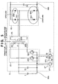
- Fig. 3 is a view of a power converter 4 according to another embodiment of the present invention.
- the power converter 4 is different from the above-described power converter 3 shown in Fig. 2 mainly in using a rectifying circuit 45 in place of the rectifying circuit 35.
- the upper arm of the rectifying circuit 45 uses MOSFETs 451 and 452.
- a gate driving unit 273 outputs a gate driving signal S2 to a high-side driver 39 and MOSFETs 223 and 353 whose source electrodes are connected to a low-side line 28. Similarly, the gate driving unit 273 outputs a gate driving signal S3 to a high-side driver 38 and MOSFETs 224 and 354.
- the high-side drivers 38 and 39 are circuits which drive the gates of the upper arm, for which the gate driving reference potential (source potential) is different from the reference potential for the lower arm. More specifically, the high-side drivers 38 and 39 apply a DC bias to the received gate driving signals S3 and S2 so that the zero potential of the gate driving signals coincides with the potentials of the source electrodes of the MOSFETs 451 and 452.
- the power for the high-side drivers 38 and 39 can be supplied from a control power supply 271.
- the high-side drivers 38 and 39 output gate driving signals S4 and S5 synchronized with the gate driving signals S3 and S2.
- the low-side lines on the primary and secondary sides of the main circuit (transformer) are connected. Accordingly, as in the first embodiment, the MOSFETs of the lower arm of the rectifying circuit 45 can be driven by using the control power supply unit 271 as a common power supply. In addition, since synchronous rectification is introduced to all components of the rectifying circuit 35, a power converter having a very high conversion efficiency can be provided.
- Fig. 4 is a view of a power converter 5 according to still another embodiment of the present invention.
- the power converter 5 is different from the above-described power converter 3 shown in Fig. 2 mainly in the structures of the main conversion circuit and transformer. More specifically, the power converter 5 is different from the power converter 3 in using a main conversion circuit 52 and transformer 53 in place of the main conversion circuit 22 and transformer 23.
- the main circuit 52 is a full-bridge inverter circuit which is arranged on the input side of the transformer to receive a power from a DC power supply 1 and output an AC power having a rectangular waveform to the transformer 23.
- the main conversion circuit 52 includes MOSFETS 521, 522, 523, and 524.
- high-side drivers 48 and 49 are gate driving circuits having the same function as that of the above-described high-side drivers 38 and 39.
- the high-side drivers 48 and 49 apply a DC bias to received gate driving signals S2 and S3 and output gate driving signals S6 and S7 to the gates of the MOSFETS 521 and 522 so that the zero potential of the gate driving signals coincides with desired potentials of the source electrodes of the MOSFETs 521 and 522.
- the power for the high-side drivers 48 and 49 can be supplied from a control power supply 271.
- the power converter according to the present invention can be applied independently of the main circuit scheme.
- a power converter which reduces the drop in forward voltage to ensure a high conversion efficiency can be provided.
- the rectifying circuit on the secondary side can be driven by using the control power supply on the primary side as a common power supply. Hence, any new power supply need not be prepared to execute synchronous rectification. Since the control system circuit can be simplified, the scale of the device can greatly be reduced.
- a power converter includes a transformer, a full-bridge rectifying circuit which is located on the secondary side of the transformer and has at least a pair of self-arc-suppressing elements which are driven while being inverted, connection means which connects the negative-pole-side connection line on the primary side of the transformer to that on the secondary side of the transformer, and a control circuit which is commonly used to drive circuits on the primary and secondary sides of the transformer.
- the self-arc-suppressing elements are driven by the control circuit.
Landscapes
- Engineering & Computer Science (AREA)
- Power Engineering (AREA)
- Mechanical Engineering (AREA)
- Dc-Dc Converters (AREA)
- Rectifiers (AREA)
Abstract
Description
Claims (9)
- A power converter characterized by comprising:wherein the self-arc-suppressing elements are driven by said control circuit.a transformer (23);a full-bridge rectifying circuit (25, 35, 45) which is located on a secondary side of said transformer and has at least a pair of self-arc-suppressing elements (253, 254, 353, 354) which are driven while being inverted;connection means (28) for connecting a negative-pole-side connection line on a primary side of said transformer to a negative-pole-side connection line on the secondary side of said transformer; anda control circuit (27) which is commonly used to drive circuits on the primary side and secondary side of said transformer,
- The converter according to claim 1, characterized in that said control circuit receives a power supplied from the circuit on the primary side of said transformer.
- The converter according to claim 1 or 2, characterized in that in said full-bridge rectifying circuit, another pair of elements are formed from non-self-arc-suppressing elements (251, 252).
- The converter according to claim 1 or 2, characterized in that in said full-bridge rectifying circuit, another pair of elements which are driven while being inverted are formed from self-arc-suppressing elements (451, 452).
- The converter according to any one of claims 1 to 4, characterized in that said transformer comprises a full-bridge inverter circuit (52) as an input stage.
- A power converter characterized by comprising:wherein the first and fourth self-arc-suppressing elements are driven on the basis of a first driving signal (S3) from said control circuit, anda transformer (23);a full-bridge rectifying circuit (45) which is located on a secondary side of said transformer and has a first self-arc-suppressing element (451), a second self-arc-suppressing element (452), a third self-arc-suppressing element (353), and a fourth self-arc-suppressing element (354);connection means (28) for connecting a negative-pole-side connection line on a primary side of said transformer to a negative-pole-side connection line on the secondary side of said transformer; anda control circuit (27) which is commonly used to drive circuits on the primary side and secondary side of said transformer,
the second and third self-arc-suppressing elements are driven on the basis of a second driving signal (S2) from said control circuit. - The converter according to claim 6, characterized in that said control circuit receives a power supplied from the circuit on the primary side of said transformer.
- The converter according to claim 6 or 7, characterized by further comprising a first bias circuit (38) which applies a bias to the first driving signal,
wherein the first self-arc-suppressing element is driven by the first driving signal to which the bias is applied by said first bias circuit. - The converter according to claim 8, characterized by further comprising a second bias circuit (39) which applies a bias to the second driving signal,
wherein the second self-arc-suppressing element is driven by the second driving signal to which the bias is applied by said second bias circuit.
Applications Claiming Priority (2)
| Application Number | Priority Date | Filing Date | Title |
|---|---|---|---|
| JP2003132153 | 2003-05-09 | ||
| JP2003132153A JP2004336943A (en) | 2003-05-09 | 2003-05-09 | Power converter |
Publications (2)
| Publication Number | Publication Date |
|---|---|
| EP1475881A2 true EP1475881A2 (en) | 2004-11-10 |
| EP1475881A3 EP1475881A3 (en) | 2006-04-19 |
Family
ID=32985682
Family Applications (1)
| Application Number | Title | Priority Date | Filing Date |
|---|---|---|---|
| EP04010785A Withdrawn EP1475881A3 (en) | 2003-05-09 | 2004-05-06 | Power converter |
Country Status (5)
| Country | Link |
|---|---|
| US (1) | US20040223281A1 (en) |
| EP (1) | EP1475881A3 (en) |
| JP (1) | JP2004336943A (en) |
| KR (1) | KR20040096782A (en) |
| CN (1) | CN1551471A (en) |
Cited By (2)
| Publication number | Priority date | Publication date | Assignee | Title |
|---|---|---|---|---|
| JP2013115928A (en) * | 2011-11-29 | 2013-06-10 | Sanken Electric Co Ltd | Synchronous rectification circuit |
| US9369058B2 (en) | 2010-08-13 | 2016-06-14 | Auckland Uniservices Limited | Inductive power transfer control |
Families Citing this family (8)
| Publication number | Priority date | Publication date | Assignee | Title |
|---|---|---|---|---|
| JP2005310980A (en) * | 2004-04-20 | 2005-11-04 | Canon Inc | Inductors and transformers |
| WO2010113218A1 (en) * | 2009-04-01 | 2010-10-07 | 三菱電機株式会社 | Power conversion apparatus |
| JP5552752B2 (en) * | 2009-04-15 | 2014-07-16 | セイコーエプソン株式会社 | Power receiving device, electronic device and non-contact power transmission system |
| JP5530401B2 (en) * | 2011-05-26 | 2014-06-25 | 株式会社日立情報通信エンジニアリング | Power supply |
| CN102882417A (en) * | 2012-10-12 | 2013-01-16 | 广东易事特电源股份有限公司 | UPS isolated bidirectional DC converter |
| JP6111970B2 (en) * | 2013-10-11 | 2017-04-12 | 株式会社デンソー | Power converter control method |
| CN104816985B (en) * | 2015-04-21 | 2017-01-25 | 艾志(南京)环保管接技术股份有限公司 | Ropy packing apparatus integrating measurement, cutting and protection functions |
| JP7605568B2 (en) * | 2021-06-14 | 2024-12-24 | パナソニックオートモーティブシステムズ株式会社 | DC-DC converter and vehicle |
Family Cites Families (16)
| Publication number | Priority date | Publication date | Assignee | Title |
|---|---|---|---|---|
| US4399499A (en) * | 1981-12-18 | 1983-08-16 | Gte Automatic Electric Labs Inc. | Bi-lateral four quadrant power converter |
| US4870555A (en) * | 1988-10-14 | 1989-09-26 | Compaq Computer Corporation | High-efficiency DC-to-DC power supply with synchronous rectification |
| US4953068A (en) * | 1989-11-08 | 1990-08-28 | Unisys Corporation | Full bridge power converter with multiple zero voltage resonant transition switching |
| US5255174A (en) * | 1991-10-18 | 1993-10-19 | Allied-Signal Inc. | Regulated bi-directional DC-to-DC voltage converter which maintains a continuous input current during step-up conversion |
| US5414609A (en) * | 1992-08-25 | 1995-05-09 | Square D Company | DC to DC/DC to AC power conversion system |
| JP2771096B2 (en) * | 1993-06-11 | 1998-07-02 | キヤノン株式会社 | Power control device, power control method, and power generation device |
| JP2810630B2 (en) * | 1993-11-16 | 1998-10-15 | キヤノン株式会社 | Solar cell power control device, power control system, power control method, and voltage / current output characteristic measurement method |
| JP3651972B2 (en) * | 1995-07-26 | 2005-05-25 | キヤノン株式会社 | Control device for grid-connected inverter and photovoltaic power generation system using the same |
| JPH0962387A (en) * | 1995-08-29 | 1997-03-07 | Canon Inc | Method and apparatus for controlling power of battery power supply, and battery power supply system |
| JP3327774B2 (en) * | 1996-06-03 | 2002-09-24 | キヤノン株式会社 | Solar power system |
| JP3416461B2 (en) * | 1997-05-30 | 2003-06-16 | キヤノン株式会社 | Solar battery charge control device |
| JP2001519999A (en) * | 1998-02-03 | 2001-10-23 | コーニンクレッカ フィリップス エレクトロニクス エヌ ヴィ | Switching voltage converter by synchronous rectification |
| GB2370431A (en) * | 2000-12-19 | 2002-06-26 | Brian Victor Olliver | A dc-ac-dc power converter |
| US6452815B1 (en) * | 2001-02-22 | 2002-09-17 | Lizhi Zhu | Accelerated commutation for passive clamp isolated boost converters |
| US6429629B1 (en) * | 2001-03-08 | 2002-08-06 | Tranh To Nguyen | Switch-mode power supplies |
| US6603675B1 (en) * | 2002-01-17 | 2003-08-05 | Abb Ab | Apparatus and a method for voltage conversion |
-
2003
- 2003-05-09 JP JP2003132153A patent/JP2004336943A/en not_active Withdrawn
-
2004
- 2004-04-30 US US10/834,931 patent/US20040223281A1/en not_active Abandoned
- 2004-04-30 CN CNA2004100385636A patent/CN1551471A/en active Pending
- 2004-05-06 EP EP04010785A patent/EP1475881A3/en not_active Withdrawn
- 2004-05-08 KR KR1020040032465A patent/KR20040096782A/en not_active Ceased
Cited By (4)
| Publication number | Priority date | Publication date | Assignee | Title |
|---|---|---|---|---|
| US9369058B2 (en) | 2010-08-13 | 2016-06-14 | Auckland Uniservices Limited | Inductive power transfer control |
| US9912250B2 (en) | 2010-08-13 | 2018-03-06 | Auckland Uniservices Limited | Inductive power transfer control |
| US10411613B2 (en) | 2010-08-13 | 2019-09-10 | Aukland Uniservices Limited | Inductive power transfer control |
| JP2013115928A (en) * | 2011-11-29 | 2013-06-10 | Sanken Electric Co Ltd | Synchronous rectification circuit |
Also Published As
| Publication number | Publication date |
|---|---|
| CN1551471A (en) | 2004-12-01 |
| EP1475881A3 (en) | 2006-04-19 |
| JP2004336943A (en) | 2004-11-25 |
| KR20040096782A (en) | 2004-11-17 |
| US20040223281A1 (en) | 2004-11-11 |
Similar Documents
| Publication | Publication Date | Title |
|---|---|---|
| US6188592B1 (en) | Externally-driven scheme for synchronous rectification | |
| EP3681038B1 (en) | Transformer based gate drive circuit | |
| US11539299B2 (en) | Switching power supply unit and electric power supply system | |
| US6061254A (en) | Forward converter with active clamp circuit | |
| US10256736B2 (en) | DC-DC converter with polarity reversal protection | |
| US12500424B2 (en) | Power supply system and solar photovoltaic inverter | |
| JP2005316429A (en) | Power supply system used for liquid crystal display apparatus | |
| US11095229B1 (en) | High switching frequency direct AC to AC converter | |
| EP1475881A2 (en) | Power converter | |
| US6859372B2 (en) | Bridge-buck converter with self-driven synchronous rectifiers | |
| US20060083029A1 (en) | Switching power supply | |
| TW200822519A (en) | A DC/AC inverter with adjustable gate-source voltage and LCD device thereof | |
| US11165361B2 (en) | Power supply and medical system | |
| US12388343B2 (en) | Bridgeless power factor-improving converter | |
| CN115706524A (en) | Conversion circuit and adapter | |
| JPH07337005A (en) | DC / DC converter and power supply device | |
| JP2024054576A (en) | Switching control device, power conversion device and power supply system | |
| JP3341441B2 (en) | Switching power supply | |
| JP4201161B2 (en) | Switching power supply | |
| JP7778522B2 (en) | Power supply circuit and power supply device | |
| WO2000038305A1 (en) | A synchronous flyback converter | |
| JPH04183269A (en) | Multistone converter device | |
| US20240007004A1 (en) | Electronic device and driving circuit thereof | |
| CN112564457B (en) | Current transformation system and power supply circuit of IGBT driving device | |
| JP3770863B2 (en) | Synchronous rectifier circuit for switching power supply |
Legal Events
| Date | Code | Title | Description |
|---|---|---|---|
| PUAI | Public reference made under article 153(3) epc to a published international application that has entered the european phase |
Free format text: ORIGINAL CODE: 0009012 |
|
| AK | Designated contracting states |
Kind code of ref document: A2 Designated state(s): AT BE BG CH CY CZ DE DK EE ES FI FR GB GR HU IE IT LI LU MC NL PL PT RO SE SI SK TR |
|
| AX | Request for extension of the european patent |
Extension state: AL HR LT LV MK |
|
| PUAL | Search report despatched |
Free format text: ORIGINAL CODE: 0009013 |
|
| AK | Designated contracting states |
Kind code of ref document: A3 Designated state(s): AT BE BG CH CY CZ DE DK EE ES FI FR GB GR HU IE IT LI LU MC NL PL PT RO SE SI SK TR |
|
| AX | Request for extension of the european patent |
Extension state: AL HR LT LV MK |
|
| RIC1 | Information provided on ipc code assigned before grant |
Ipc: H02M 3/335 20060101ALI20060228BHEP Ipc: H02M 7/219 20060101ALI20060228BHEP Ipc: H02M 3/337 20060101AFI20040827BHEP |
|
| AKX | Designation fees paid |
Designated state(s): AT BE BG CH CY CZ DE DK EE ES FI FR GB GR HU IE IT LI LU MC NL PL PT RO SE SI SK TR |
|
| STAA | Information on the status of an ep patent application or granted ep patent |
Free format text: STATUS: THE APPLICATION IS DEEMED TO BE WITHDRAWN |
|
| 18D | Application deemed to be withdrawn |
Effective date: 20060601 |