EP1475852A1 - Lead outlet structure of secondary battery in sheet type - Google Patents
Lead outlet structure of secondary battery in sheet type Download PDFInfo
- Publication number
- EP1475852A1 EP1475852A1 EP03009748A EP03009748A EP1475852A1 EP 1475852 A1 EP1475852 A1 EP 1475852A1 EP 03009748 A EP03009748 A EP 03009748A EP 03009748 A EP03009748 A EP 03009748A EP 1475852 A1 EP1475852 A1 EP 1475852A1
- Authority
- EP
- European Patent Office
- Prior art keywords
- internal
- leads
- form package
- secondary battery
- envelope form
- Prior art date
- Legal status (The legal status is an assumption and is not a legal conclusion. Google has not performed a legal analysis and makes no representation as to the accuracy of the status listed.)
- Granted
Links
Images


Classifications
-
- H—ELECTRICITY
- H01—ELECTRIC ELEMENTS
- H01M—PROCESSES OR MEANS, e.g. BATTERIES, FOR THE DIRECT CONVERSION OF CHEMICAL ENERGY INTO ELECTRICAL ENERGY
- H01M10/00—Secondary cells; Manufacture thereof
- H01M10/05—Accumulators with non-aqueous electrolyte
- H01M10/052—Li-accumulators
- H01M10/0525—Rocking-chair batteries, i.e. batteries with lithium insertion or intercalation in both electrodes; Lithium-ion batteries
-
- H—ELECTRICITY
- H01—ELECTRIC ELEMENTS
- H01M—PROCESSES OR MEANS, e.g. BATTERIES, FOR THE DIRECT CONVERSION OF CHEMICAL ENERGY INTO ELECTRICAL ENERGY
- H01M10/00—Secondary cells; Manufacture thereof
- H01M10/04—Construction or manufacture in general
- H01M10/0413—Large-sized flat cells or batteries for motive or stationary systems with plate-like electrodes
-
- H—ELECTRICITY
- H01—ELECTRIC ELEMENTS
- H01M—PROCESSES OR MEANS, e.g. BATTERIES, FOR THE DIRECT CONVERSION OF CHEMICAL ENERGY INTO ELECTRICAL ENERGY
- H01M10/00—Secondary cells; Manufacture thereof
- H01M10/05—Accumulators with non-aqueous electrolyte
- H01M10/058—Construction or manufacture
- H01M10/0585—Construction or manufacture of accumulators having only flat construction elements, i.e. flat positive electrodes, flat negative electrodes and flat separators
-
- H—ELECTRICITY
- H01—ELECTRIC ELEMENTS
- H01M—PROCESSES OR MEANS, e.g. BATTERIES, FOR THE DIRECT CONVERSION OF CHEMICAL ENERGY INTO ELECTRICAL ENERGY
- H01M50/00—Constructional details or processes of manufacture of the non-active parts of electrochemical cells other than fuel cells, e.g. hybrid cells
- H01M50/10—Primary casings, jackets or wrappings of a single cell or a single battery
- H01M50/116—Primary casings, jackets or wrappings of a single cell or a single battery characterised by the material
- H01M50/124—Primary casings, jackets or wrappings of a single cell or a single battery characterised by the material having a layered structure
-
- H—ELECTRICITY
- H01—ELECTRIC ELEMENTS
- H01M—PROCESSES OR MEANS, e.g. BATTERIES, FOR THE DIRECT CONVERSION OF CHEMICAL ENERGY INTO ELECTRICAL ENERGY
- H01M50/00—Constructional details or processes of manufacture of the non-active parts of electrochemical cells other than fuel cells, e.g. hybrid cells
- H01M50/10—Primary casings, jackets or wrappings of a single cell or a single battery
- H01M50/131—Primary casings, jackets or wrappings of a single cell or a single battery characterised by physical properties, e.g. gas-permeability or size
- H01M50/136—Flexibility or foldability
-
- H—ELECTRICITY
- H01—ELECTRIC ELEMENTS
- H01M—PROCESSES OR MEANS, e.g. BATTERIES, FOR THE DIRECT CONVERSION OF CHEMICAL ENERGY INTO ELECTRICAL ENERGY
- H01M50/00—Constructional details or processes of manufacture of the non-active parts of electrochemical cells other than fuel cells, e.g. hybrid cells
- H01M50/10—Primary casings, jackets or wrappings of a single cell or a single battery
- H01M50/172—Arrangements of electric connectors penetrating the casing
- H01M50/174—Arrangements of electric connectors penetrating the casing adapted for the shape of the cells
- H01M50/178—Arrangements of electric connectors penetrating the casing adapted for the shape of the cells for pouch or flexible bag cells
-
- H—ELECTRICITY
- H01—ELECTRIC ELEMENTS
- H01M—PROCESSES OR MEANS, e.g. BATTERIES, FOR THE DIRECT CONVERSION OF CHEMICAL ENERGY INTO ELECTRICAL ENERGY
- H01M50/00—Constructional details or processes of manufacture of the non-active parts of electrochemical cells other than fuel cells, e.g. hybrid cells
- H01M50/10—Primary casings, jackets or wrappings of a single cell or a single battery
- H01M50/183—Sealing members
- H01M50/186—Sealing members characterised by the disposition of the sealing members
-
- H—ELECTRICITY
- H01—ELECTRIC ELEMENTS
- H01M—PROCESSES OR MEANS, e.g. BATTERIES, FOR THE DIRECT CONVERSION OF CHEMICAL ENERGY INTO ELECTRICAL ENERGY
- H01M50/00—Constructional details or processes of manufacture of the non-active parts of electrochemical cells other than fuel cells, e.g. hybrid cells
- H01M50/10—Primary casings, jackets or wrappings of a single cell or a single battery
- H01M50/183—Sealing members
- H01M50/19—Sealing members characterised by the material
- H01M50/193—Organic material
-
- H—ELECTRICITY
- H01—ELECTRIC ELEMENTS
- H01M—PROCESSES OR MEANS, e.g. BATTERIES, FOR THE DIRECT CONVERSION OF CHEMICAL ENERGY INTO ELECTRICAL ENERGY
- H01M50/00—Constructional details or processes of manufacture of the non-active parts of electrochemical cells other than fuel cells, e.g. hybrid cells
- H01M50/50—Current conducting connections for cells or batteries
- H01M50/528—Fixed electrical connections, i.e. not intended for disconnection
-
- H—ELECTRICITY
- H01—ELECTRIC ELEMENTS
- H01M—PROCESSES OR MEANS, e.g. BATTERIES, FOR THE DIRECT CONVERSION OF CHEMICAL ENERGY INTO ELECTRICAL ENERGY
- H01M50/00—Constructional details or processes of manufacture of the non-active parts of electrochemical cells other than fuel cells, e.g. hybrid cells
- H01M50/50—Current conducting connections for cells or batteries
- H01M50/543—Terminals
- H01M50/547—Terminals characterised by the disposition of the terminals on the cells
- H01M50/55—Terminals characterised by the disposition of the terminals on the cells on the same side of the cell
-
- H—ELECTRICITY
- H01—ELECTRIC ELEMENTS
- H01M—PROCESSES OR MEANS, e.g. BATTERIES, FOR THE DIRECT CONVERSION OF CHEMICAL ENERGY INTO ELECTRICAL ENERGY
- H01M50/00—Constructional details or processes of manufacture of the non-active parts of electrochemical cells other than fuel cells, e.g. hybrid cells
- H01M50/50—Current conducting connections for cells or batteries
- H01M50/543—Terminals
- H01M50/552—Terminals characterised by their shape
- H01M50/553—Terminals adapted for prismatic, pouch or rectangular cells
-
- H—ELECTRICITY
- H01—ELECTRIC ELEMENTS
- H01M—PROCESSES OR MEANS, e.g. BATTERIES, FOR THE DIRECT CONVERSION OF CHEMICAL ENERGY INTO ELECTRICAL ENERGY
- H01M50/00—Constructional details or processes of manufacture of the non-active parts of electrochemical cells other than fuel cells, e.g. hybrid cells
- H01M50/10—Primary casings, jackets or wrappings of a single cell or a single battery
- H01M50/116—Primary casings, jackets or wrappings of a single cell or a single battery characterised by the material
- H01M50/117—Inorganic material
- H01M50/119—Metals
-
- H—ELECTRICITY
- H01—ELECTRIC ELEMENTS
- H01M—PROCESSES OR MEANS, e.g. BATTERIES, FOR THE DIRECT CONVERSION OF CHEMICAL ENERGY INTO ELECTRICAL ENERGY
- H01M50/00—Constructional details or processes of manufacture of the non-active parts of electrochemical cells other than fuel cells, e.g. hybrid cells
- H01M50/10—Primary casings, jackets or wrappings of a single cell or a single battery
- H01M50/116—Primary casings, jackets or wrappings of a single cell or a single battery characterised by the material
- H01M50/121—Organic material
-
- H—ELECTRICITY
- H01—ELECTRIC ELEMENTS
- H01M—PROCESSES OR MEANS, e.g. BATTERIES, FOR THE DIRECT CONVERSION OF CHEMICAL ENERGY INTO ELECTRICAL ENERGY
- H01M50/00—Constructional details or processes of manufacture of the non-active parts of electrochemical cells other than fuel cells, e.g. hybrid cells
- H01M50/10—Primary casings, jackets or wrappings of a single cell or a single battery
- H01M50/116—Primary casings, jackets or wrappings of a single cell or a single battery characterised by the material
- H01M50/124—Primary casings, jackets or wrappings of a single cell or a single battery characterised by the material having a layered structure
- H01M50/126—Primary casings, jackets or wrappings of a single cell or a single battery characterised by the material having a layered structure comprising three or more layers
- H01M50/129—Primary casings, jackets or wrappings of a single cell or a single battery characterised by the material having a layered structure comprising three or more layers with two or more layers of only organic material
-
- H—ELECTRICITY
- H01—ELECTRIC ELEMENTS
- H01M—PROCESSES OR MEANS, e.g. BATTERIES, FOR THE DIRECT CONVERSION OF CHEMICAL ENERGY INTO ELECTRICAL ENERGY
- H01M50/00—Constructional details or processes of manufacture of the non-active parts of electrochemical cells other than fuel cells, e.g. hybrid cells
- H01M50/50—Current conducting connections for cells or batteries
- H01M50/531—Electrode connections inside a battery casing
- H01M50/54—Connection of several leads or tabs of plate-like electrode stacks, e.g. electrode pole straps or bridges
-
- Y—GENERAL TAGGING OF NEW TECHNOLOGICAL DEVELOPMENTS; GENERAL TAGGING OF CROSS-SECTIONAL TECHNOLOGIES SPANNING OVER SEVERAL SECTIONS OF THE IPC; TECHNICAL SUBJECTS COVERED BY FORMER USPC CROSS-REFERENCE ART COLLECTIONS [XRACs] AND DIGESTS
- Y02—TECHNOLOGIES OR APPLICATIONS FOR MITIGATION OR ADAPTATION AGAINST CLIMATE CHANGE
- Y02E—REDUCTION OF GREENHOUSE GAS [GHG] EMISSIONS, RELATED TO ENERGY GENERATION, TRANSMISSION OR DISTRIBUTION
- Y02E60/00—Enabling technologies; Technologies with a potential or indirect contribution to GHG emissions mitigation
- Y02E60/10—Energy storage using batteries
-
- Y—GENERAL TAGGING OF NEW TECHNOLOGICAL DEVELOPMENTS; GENERAL TAGGING OF CROSS-SECTIONAL TECHNOLOGIES SPANNING OVER SEVERAL SECTIONS OF THE IPC; TECHNICAL SUBJECTS COVERED BY FORMER USPC CROSS-REFERENCE ART COLLECTIONS [XRACs] AND DIGESTS
- Y02—TECHNOLOGIES OR APPLICATIONS FOR MITIGATION OR ADAPTATION AGAINST CLIMATE CHANGE
- Y02P—CLIMATE CHANGE MITIGATION TECHNOLOGIES IN THE PRODUCTION OR PROCESSING OF GOODS
- Y02P70/00—Climate change mitigation technologies in the production process for final industrial or consumer products
- Y02P70/50—Manufacturing or production processes characterised by the final manufactured product
Definitions
- the present invention relates to a lead outlet structure of secondary battery in sheet type.
- the present invention relates to, it is not limited to them though, a lead outlet structure of a large capacity secondary battery in sheet type for an electric vehicle, a UPS (uninterrupted power supply), a road leveling and so on.
- UPS uninterrupted power supply
- One of secondary batteries that have higher capacity or more energy per volume or weight and have higher energy density is, for example, a lithium ion rechargeable battery that is a secondary battery with non-aqueous electrolyte, is composed of lithium or lithium alloy.
- This lithium ion battery has advantages such as no memory effect, little self-discharge and so on, therefore, it is widely used for video camera recorders, audio equipment, portable computers, mobile phones, various electric equipment, communication devices, optical equipment and audio equipment.
- This lithium ion secondary battery generally composes of an electrode pair, a battery housing which encloses this electrode pair and seals it inside with electrolyte, and a cathode lead and an anode lead those are connected from each of cathode electrode and anode electrode of the electrode pair to each of cathode terminal and anode terminal which are incorporated on the battery housing, where the electrode pair consists of sheets of cathode electrode that consists of a sheet of cathode collector and cathode active material coated on it, sheets of anode electrode that consists of a sheet of anode collector and anode active material coated on it and a separator that is stacked between them.
- a lithium goes out of cathode active material and gets into electrolyte as an ion, then gets into anode active material, while during discharging, this lithium ion gets out of anode material and gets into electrolyte and goes back into cathode material.
- lithium ion secondary battery like this is expected to use, for example, as a large capacity secondary battery for electric vehicle use. And a plenty of development and proposal have been conducted in this area so far. Not only relatively small secondary batteries used for electric equipment, communication devices, optical equipment, audio devices and so on, but also larger secondary batteries for electric vehicles, are requested to be smaller in size, lighter in weight, thinner in thickness and free in shape.
- a flexible envelope form package of three layer laminated film that is composed of an inner layer of thermoplastic resin such as polyethylene or polypropylene which are stable with electrolyte and suitable for heat-sealing, a middle layer of metal foil that is flexible and strong such as aluminum foil and an external layer of insulating resin such as polyamide resin, which shows good electrical insulation.
- thermoplastic resin such as polyethylene or polypropylene
- middle layer of metal foil that is flexible and strong such as aluminum foil
- an external layer of insulating resin such as polyamide resin
- this conventional lithium ion secondary battery in sheet type B consists of an internal electrode pair 1 in sheet type that is generally composed of cathode electrode 1a in sheet type, anode electrode 1b in sheet type and separator 1c stacked between them and a flexible envelope form package 2 that is made of laminated film which has an internal layer 2a of thermoplastic resin, a middle layer 2b of metal foil and an external layer 2c of insulating resin, which contains the above-mentioned internal electrode pair 1 and electrolyte inside. And also inside this envelope form package 2, each of cathode electrode 1a and each of anode electrode 1b are connected to a pair of cathode lead 3a and anode lead 3b, respectively.
- this pair of cathode lead 3a and anode lead 3b goes hermetically through heat sealed portion 4 of the envelope form package 2 and is fixed to this heat sealed portion. And the projected external portions of the cathode lead 3a and anode lead 3b out of the heat sealed portion 4 are used as terminals or external leads.
- heat sealed portion between the cathode lead 3a and the envelope form package 2 may have an opening and in some cases, water may go inside through this opening andmay produce hydrogen fluoride, then the battery may deteriorate or the electrolyte may go out of the envelope form package 2.
- an objective of the present invention is to provide a lead outlet structure of a secondary battery in sheet type, which accomplishes a relatively large capacity secondary battery as a secondary battery in sheet type, which uses an envelope form package as a battery housing and at the same time it can be light, thin and flexible
- the present invention is a lead outlet structure of secondary battery in sheet type, which comprises; an internal electrode pair in sheet type which is obtained by stacking alternately sheets of cathode electrode and sheets of anode electrode with separator between them, a flexible envelope form package that contains inside hermetically this internal electrode pair and electrolyte, a pair of internal leads that are respectively connected with separately each of cathode electrode and each of anode electrode of the internal electrode pair inside the envelope form package, a pair of external leads that are provided on the outside of the above-mentioned envelope form package corresponding to each of the above-mentioned internal leads with the above-mentioned envelope form package in between, and a pair of connecting means, one side of which is connected to each of the internal leads inside the above-mentioned envelope formpackage and the other side is connected to each of the external leads on the outside of the envelope form package as well so that each of the internal leads and each of the external leads are electrically connected.
- An envelope form package in the present invention is not limited to something special, as far as it has practical strength to be a battery housing of a secondary battery in sheet type and at the same time it is stable with electrolyte that is contained inside.
- a flexible envelope form package that has three layer laminated film that consists of; an internal layer of thermoplastic resin that are stable with electrolyte and suitable for heat-sealing, for example, polyethylene, polypropylene, polystyrene, polyamide, ionomer and so on, an middle layer of metal foil that is flexible and strong, for example, aluminum foil, stainless steel foil and so on and an external layer of insulating resin that has good electrical insulation, for example, polyamide system resin, polyester system resin and so on.
- each of cathode electrode sheets of an internal electrode pair are connected by cathode internal leads and at the same time each of anode electrode sheets are connected by anode internal leads.
- each of external leads for cathode and anode are provided on the position on the outside of the envelope form package corresponding to the above-mentioned internal cathode and anode leads and a pair of connecting means that goes hermetically through the envelope form package connects electrically between the internal cathode lead and the external cathode lead and between the internal anode lead and the external anode lead.
- the size of the above-mentioned internal leads and external leads is designed to the capacity, volume, weight or application of a secondary battery in sheet type, though, preferably it should be in stripe form, for instance, of more than about 0.5mm, preferably 1 to 5 mm thickness, which is relatively thicker compared to conventional leads for a secondary battery.
- metal such as aluminum, aluminum alloy, copper, and nickel is preferred to be used, and preferably the same material as that of the cathode collector, for example, aluminum or aluminum alloy is preferred to be used for the internal cathode lead and the external cathode lead.
- the same material as that of the anode collector for example, copper and/or nickel is preferred to be used for the internal anode lead and the external anode lead.
- this connecting means such as a rivet concerns, it is good enough as far as it connects firmly these internal leads and external leads and connects electrically them.
- a riveting with solid rivets hereinafter referred as 'rivets'
- full tubular rivets semi-tubular rivets
- split rivets split rivets
- compression rivets blind rivets
- blind rivets a fixing means where one of an external lead or an internal lead has a stud that is integral or is fixed to it and at the same time the other lead has a hole to receive the stud to connect and fix them by clamping the top of the stud
- a fixing means by a bolt and a nut are samples of this connecting means.
- rivets that comprise this connecting means preferably for connecting an internal cathode lead and an external cathode lead, it is preferred to use aluminum or aluminum alloy, those are the same material that is used for the internal lead. And for connecting an internal anode lead and an external anode lead, it is preferred to use copper and/or nickel, those are the same material that is used for the internal lead.
- penetrating holes on an envelope form package which a connecting means goes through to connect internal leads and external leads are required to be hermetically sealed.
- sealing parts may be installed between an internal lead and the envelope form package and/or between an external lead and the envelope form package in order to seal the penetrating holes on the envelope form package, which the connecting means goes through, or thickness of the internal layer and/or the external layer around these penetrating holes that this connecting means goes through may be formed thicker than other areas beforehand and when the connecting means connect between the internal leads and the external leads, it may seal the penetrating holes by the thicker area around the penetrating holes.
- sealing parts installed between the internal lead and the envelope form package are required to be made of synthetic resin that is stable with electrolyte and it is preferred to be made of thermoplastic resin, such as polypropylene, polyethylene, polyimide, polyamide, polyethylene telephthalate, polytetrafluoroethylene, or fluorocarbon polymers, same as or similar to an internal layer of laminated film that comprises the envelope form package.
- thermoplastic resin such as polypropylene, polyethylene, polyimide, polyamide, polyethylene telephthalate, polytetrafluoroethylene, or fluorocarbon polymers
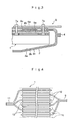
- Fig. shows a diagonal diagramof a lithium ion secondary battery in sheet type that has a lead outlet structure related with an embodiment of the present invention.
- Fig. 2 is a sectional drawing at II-II line in fig. 1.
- Fig. 3 indicates a sectional drawing at III-III line in fig.1.
- Fig. 4 illustrates an internal electrode pair installed inside an envelope form package in fig. 1.
- Fig. 5 shows a diagonal diagram of a lithium ion secondary battery in sheet type that has a conventional lead outlet structure.
- Fig. 6 indicates a sectional drawing at VI-VI line in fig.5.
- B-lithium ion secondary battery in sheet type 1-internal electrode pair, la-cathode electrode, 1b-anode electrode, 1c-separator, 2- envelope from package, 4-heat sealed portion, 5a, 5b-internal leads, 6a, 6b-external leads, 7a, 7b-rivet, 8a, 8b-sealing parts, 9-cathode collector, 10-cathode active material, 11-anode collector, 12-anode active material.
- FIG. 1 A lithium ion secondary battery in sheet type, applied the present invention of a lead outlet structure, is indicated in figure 1 to 3.
- Figure 2 and 3 now show a section of cathode leads and the cathode leads are mainly explained below, since structure of anode leads are same as that of the cathode leads.
- the present embodiment of a secondary battery in sheet type B comprises; an internal electrode pair in sheet type 1 which is obtained by stacking alternately sheets of cathode electrode 1a and sheets of anode electrode 1b with separator 1c between them, a flexible envelope form package 2 that contains inside hermetically this internal electrode pair 1 and electrolyte (not shown), an internal cathode lead 5a that connects each of cathode electrode sheets 1a of the internal electrode pair 1 inside the envelope form package 2, an internal anode lead (5b, not shown) that connects each of anode electrode sheets 1b of the internal electrode pair 1 inside the envelope form package 2, an external cathode lead 6a that are provided on the outside of the above-mentioned envelope 2 form package corresponding to the above-mentioned internal cathode lead 5a with the above-mentioned envelope form package 2 in between, an external anode lead 6b that are provided on the outside of the above-mentioned envelope form package 2, corresponding to the above-mentioned internal anode lead
- Sealing parts 8a and 8b are in this embodiment installed between each of the internal leads 5a, 5b and the envelope form package 2 as well as between each of the external leads 6a, 6b and the envelope form package 2 in order to seal the rivet holes on the envelope form package 2, through which the rivets 7a, 7b are inserted.
- sign 4 shows the heat sealed portion of the envelope form package 2.
- the above mentioned electrode pair 1 consists of cathode electrode 1a, which is composed of aluminum cathode collector 9 coated on both sides with cathode active material 10, and anode electrode 1b, which is composed of copper anode collector 11 coated on both sides with anode active material 12.
- a cathode internal lead 5a, a cathode external lead 6a and a rivet 7a that connects them are made of aluminum, same as the above mentioned cathode collector.
- An anode internal lead 5b, an anode external lead 6b and the rivet 7b that connects them are made of copper, same as the above mentioned anode collector
- the above mentioned envelope formpackage 2 consists of laminated filmof three layers, such as a polyethylene internal layer 2a, an aluminum foil middle layer 2b and a nylon external layer 2c.
- a sealing part 8a that is installed between the above mentioned internal leads 5a, 5b, and the envelope form package 2 are made of polyethylene, same as the internal layer 2a of the envelope form package 2, and a sealing part 8b that is installed between the above mentioned internal leads 6a and 6b, and the envelope form package 2 are made of nylon, same as the external layer 2c of the envelope form package 2,
- One hundred lithium ion batteries of 4.2V and 10Ah in sheet type that is similar form to the embodiment, which comprise an internal electrode pair of 120 mm x 300 mm x 5 mm in size, internal leads of aluminum or copper of 15 mm x 100 mm x 1.5 mm in size, external leads of aluminum or copper of 15 mm x 100 mm x 1.5 mm in size, rivets of aluminum or copper of 4 mm diameter x 6 mm in size, an envelope form package that consists of an internal layer of polyethylene of 0.08 mm thickness, an middle layer of aluminum foil of 0.04 mm thickness and an external layer of nylon of 0.03 mm thickness, and electrolyte of mixture of ethylene carbonate (EC) and diethyl carbonate (DEC), were fabricated, were stored at 80 degree C for one week, and then electrolyte leakage occurrences were counted and the voltages were checked. As a result, no electrolyte leakage was found and the voltages after the storage were among 4.12 to 4.18V.
- lithium ion batteries of 10 Ah and 4. 2V which have the same composition except that external leads are extended portions of internal leads through heat sealed portion of an envelope form package, were fabricated, were stored at 80 degree C for one week, and then electrolyte leakage occurrences were counted and the voltages were checked. As a result, 45 batteries was found to have electrolyte leakage and the voltages after the storage were among 0 to 4.0V.
- the lithium ion secondary batteries with conventional structure of the comparison sample have large self-discharge, and about half of the samples have electrolyte leakage.
- the lithium ion secondary batteries with a structure of the present invention have small self discharge such as about 0.05V and none of the samples has electrolyte leakage.
- the batteries When a lead outlet structure of this present invention is employed, among secondary batteries in sheet type with an envelope form package as a battery housing, the batteries have light, thin and flexible characteristics and at the same time secondary batteries with relatively large capacity can be achieved. Especially this structure is highly suitable for a lead outlet structure of a lithium ion secondary battery in sheet type with relatively large capacity.
Abstract
Description
- The present invention relates to a lead outlet structure of secondary battery in sheet type. For example, , the present invention relates to, it is not limited to them though, a lead outlet structure of a large capacity secondary battery in sheet type for an electric vehicle, a UPS (uninterrupted power supply), a road leveling and so on.
- One of secondary batteries that have higher capacity or more energy per volume or weight and have higher energy density is, for example, a lithium ion rechargeable battery that is a secondary battery with non-aqueous electrolyte, is composed of lithium or lithium alloy. This lithium ion battery has advantages such as no memory effect, little self-discharge and so on, therefore, it is widely used for video camera recorders, audio equipment, portable computers, mobile phones, various electric equipment, communication devices, optical equipment and audio equipment.
- This lithium ion secondary battery generally composes of an electrode pair, a battery housing which encloses this electrode pair and seals it inside with electrolyte, and a cathode lead and an anode lead those are connected from each of cathode electrode and anode electrode of the electrode pair to each of cathode terminal and anode terminal which are incorporated on the battery housing, where the electrode pair consists of sheets of cathode electrode that consists of a sheet of cathode collector and cathode active material coated on it, sheets of anode electrode that consists of a sheet of anode collector and anode active material coated on it and a separator that is stacked between them.
During charging, a lithium goes out of cathode active material and gets into electrolyte as an ion, then gets into anode active material, while during discharging, this lithium ion gets out of anode material and gets into electrolyte and goes back into cathode material. - Since it can accomplish its high energy density, lithium ion secondary battery like this is expected to use, for example, as a large capacity secondary battery for electric vehicle use. And a plenty of development and proposal have been conducted in this area so far.
Not only relatively small secondary batteries used for electric equipment, communication devices, optical equipment, audio devices and so on, but also larger secondary batteries for electric vehicles, are requested to be smaller in size, lighter in weight, thinner in thickness and free in shape. - Therefore, conventionallyinregardof abatteryhousing, a flexible envelope form package of three layer laminated film that is composed of an inner layer of thermoplastic resin such as polyethylene or polypropylene which are stable with electrolyte and suitable for heat-sealing, a middle layer of metal foil that is flexible and strong such as aluminum foil and an external layer of insulating resin such as polyamide resin, which shows good electrical insulation.
Light, thin, and flexible lithium ion secondary batteries in sheet type are proposed to be obtained by inserting an internal electrode pair in sheet type and electrolyte into the above-mentioned envelope form package. - And as indicated in figure 5 and figure 6, this conventional lithium ion secondary battery in sheet type B consists of an internal electrode pair 1 in sheet type that is generally composed of
cathode electrode 1a in sheet type,anode electrode 1b in sheet type andseparator 1c stacked between them and a flexibleenvelope form package 2 that is made of laminated film which has aninternal layer 2a of thermoplastic resin, amiddle layer 2b of metal foil and anexternal layer 2c of insulating resin, which contains the above-mentioned internal electrode pair 1 and electrolyte inside. And also inside thisenvelope form package 2, each ofcathode electrode 1a and each ofanode electrode 1b are connected to a pair ofcathode lead 3a and anode lead 3b, respectively. In addition, this pair ofcathode lead 3a and anode lead 3b goes hermetically through heat sealedportion 4 of theenvelope form package 2 and is fixed to this heat sealed portion. And the projected external portions of thecathode lead 3a and anode lead 3b out of the heat sealedportion 4 are used as terminals or external leads. - In this structure of electrode leads, the surface between the envelope from
package 2, thecathode lead 3a and the anode lead 3b, which are extended, as external leads or terminals, to the outside of theenvelope form package 2 is adhered by heat-sealing ofinner layer 2a of thermoplastic resin of theenvelope form package 2. And adhesion strength between thesecathode lead 3a and anode lead 3b and anenvelope form package 2 is not sufficient, especially the larger the capacity becomes, the heavier the cell becomes inevitably, consequently adhesion between acathode lead 3a and an anode lead 3b, and anenvelope form package 2 becomes unreliable with heat seal only. And if material of acathode lead 3a is aluminum as in normal case, the adhesion strength on thisaluminum cathode lead 3a becomes more unreliable, then heat sealed portion between thecathode lead 3a and theenvelope form package 2 may have an opening and in some cases, water may go inside through this opening andmay produce hydrogen fluoride, then the battery may deteriorate or the electrolyte may go out of theenvelope form package 2. - Moreover, when capacity becomes larger and as a result large drain is desired, the section area of leads that is conducted from the inside electrode pair (cathode electrode and anode electrode) through the envelope form package to the outside is also required to be large. Then the larger this section area is, the more frequently the above-mentioned problems occur. For this reason a sheet type lithium ion battery in an envelope form package with capacity of more than 3Ah is considered to be difficult to achieve, although it is expected to contribute to smaller or lighter equipment, machines, or automobiles with these lighter, thinner, flexible and versatile characteristics.
- Then after the inventors of the present invention examined whole heartedly lead outlet structures of electrode which can construct a relatively large capacity, preferably more than 5 Ah, batteries without spoiling advantages such as light, thin, flexible characteristics as secondary batteries in sheet type have, using an envelope form package of three layer laminated film like this, they completed the present invention by finding that an envelope form package between each of the internal leads and the external leads are fixed firmly and hermetically by connecting between the pair of internal leads that is respectively connected to each of the cathode electrode and the anode electrode of the electrode pair inside the envelope form package and the pair of the external leads provided on the outside surface of the envelope form package, through the envelope form package by a pair of connecting means, whose one end is connected to each of the internal leads inside the envelope form package and the other end at the same time is connected to each of the external leads outside the envelope form package, and by electrically connecting each of the internal leads and each of the external leads by this pair of connecting means.
- Hence, an objective of the present invention is to provide a lead outlet structure of a secondary battery in sheet type, which accomplishes a relatively large capacity secondary battery as a secondary battery in sheet type, which uses an envelope form package as a battery housing and at the same time it can be light, thin and flexible
- The present invention is a lead outlet structure of secondary battery in sheet type, which comprises; an internal electrode pair in sheet type which is obtained by stacking alternately sheets of cathode electrode and sheets of anode electrode with separator between them, a flexible envelope form package that contains inside hermetically this internal electrode pair and electrolyte, a pair of internal leads that are respectively connected with separately each of cathode electrode and each of anode electrode of the internal electrode pair inside the envelope form package, a pair of external leads that are provided on the outside of the above-mentioned envelope form package corresponding to each of the above-mentioned internal leads with the above-mentioned envelope form package in between, and a pair of connecting means, one side of which is connected to each of the internal leads inside the above-mentioned envelope formpackage and the other side is connected to each of the external leads on the outside of the envelope form package as well so that each of the internal leads and each of the external leads are electrically connected.
- An envelope form package in the present invention is not limited to something special, as far as it has practical strength to be a battery housing of a secondary battery in sheet type and at the same time it is stable with electrolyte that is contained inside. One example is a flexible envelope form package that has three layer laminated film that consists of; an internal layer of thermoplastic resin that are stable with electrolyte and suitable for heat-sealing, for example, polyethylene, polypropylene, polystyrene, polyamide, ionomer and so on, an middle layer of metal foil that is flexible and strong, for example, aluminum foil, stainless steel foil and so on and an external layer of insulating resin that has good electrical insulation, for example, polyamide system resin, polyester system resin and so on.
- And in this invention inside the above-mentioned envelope form package, each of cathode electrode sheets of an internal electrode pair are connected by cathode internal leads and at the same time each of anode electrode sheets are connected by anode internal leads. And also each of external leads for cathode and anode are provided on the position on the outside of the envelope form package corresponding to the above-mentioned internal cathode and anode leads and a pair of connecting means that goes hermetically through the envelope form package connects electrically between the internal cathode lead and the external cathode lead and between the internal anode lead and the external anode lead.
- The size of the above-mentioned internal leads and external leads is designed to the capacity, volume, weight or application of a secondary battery in sheet type, though, preferably it should be in stripe form, for instance, of more than about 0.5mm, preferably 1 to 5 mm thickness, which is relatively thicker compared to conventional leads for a secondary battery. And also as far as material concerns, same as material and shape of leads used for a conventional secondary battery of this kind, metal such as aluminum, aluminum alloy, copper, and nickel is preferred to be used, and preferably the same material as that of the cathode collector, for example, aluminum or aluminum alloy is preferred to be used for the internal cathode lead and the external cathode lead. And as the same material as that of the anode collector, for example, copper and/or nickel is preferred to be used for the internal anode lead and the external anode lead.
- As far as material of this connecting means such as a rivet concerns, it is good enough as far as it connects firmly these internal leads and external leads and connects electrically them. For instance, a riveting with solid rivets (hereinafter referred as 'rivets'), full tubular rivets, semi-tubular rivets, split rivets, compression rivets, blind rivets and so on, a fixing means where one of an external lead or an internal lead has a stud that is integral or is fixed to it and at the same time the other lead has a hole to receive the stud to connect and fix them by clamping the top of the stud, or a fixing means by a bolt and a nut are samples of this connecting means.
- Further, regarding material of rivets that comprise this connecting means, preferably for connecting an internal cathode lead and an external cathode lead, it is preferred to use aluminum or aluminum alloy, those are the same material that is used for the internal lead. And for connecting an internal anode lead and an external anode lead, it is preferred to use copper and/or nickel, those are the same material that is used for the internal lead. As describedhere, whenaluminumor aluminum alloy which is same as the material used for the cathode collector is used as material of the internal cathode lead, the external cathode lead and the connecting means, and copper and/or nickel which is same as the material used for the anode collector is used as material of the internal anode lead, the external anode lead and the connecting means, it can reduce its contact resistance as well as it canprevent thermal deformation due to their different coefficient of thermal expansion.
- Moreover, in the present invention, penetrating holes on an envelope form package, which a connecting means goes through to connect internal leads and external leads are required to be hermetically sealed. There is no restriction to how to seal hermetically these penetrating holes of the envelope form packages, however, for example, sealing parts may be installed between an internal lead and the envelope form package and/or between an external lead and the envelope form package in order to seal the penetrating holes on the envelope form package, which the connecting means goes through, or thickness of the internal layer and/or the external layer around these penetrating holes that this connecting means goes through may be formed thicker than other areas beforehand and when the connecting means connect between the internal leads and the external leads, it may seal the penetrating holes by the thicker area around the penetrating holes.
- And, in the case of the above-mentioned sealing parts installation, at least sealing parts installed between the internal lead and the envelope form package are required to be made of synthetic resin that is stable with electrolyte and it is preferred to be made of thermoplastic resin, such as polypropylene, polyethylene, polyimide, polyamide, polyethylene telephthalate, polytetrafluoroethylene, or fluorocarbon polymers, same as or similar to an internal layer of laminated film that comprises the envelope form package.
- Regarding a lead outlet structure of a secondary battery in sheet type, position on an envelope form package, where an external lead is provided, has no restriction, as far as it can be installed with the corresponding internal lead.
- There is no restriction regarding manufacturing procedure of a secondary battery that has a lead outlet structure of the present invention, however, if a flat rectangle sheet type secondary battery is fabricated with rivets as connecting means, for instance, the following procedure fabricates it easily.
- (1) First, connect internal cathode and anode leads to the specified position of an internal electrode pair.
- (2) Next, insert the internal electrode pair into an envelope form package, whose three sides are heat-sealed.
- (3) Place external leads on the position of the outside of the envelope form package, corresponding to the internal leads and align rivet holes of the internal leads, the external leads and penetrating holes of the envelope form package.
-
- (4) Insert rivets into the rivet holes and the penetrating holes and add force on the rivet axis that sticks out through the rivet holes of the internal leads and the external leads by means of strikes, hydraulic force or air pressure to clamp the tops of the rivets that stick out through the rivet holes.
- (5) Seal hermetically by heat-sealing the unsealed side of the envelope form package.
- (6) Make a relatively small opening, for example, by cutting one edge of the envelope form package.
- (7) Fill the envelope form package with electrolyte through the opening and at the same time seal this opening by heat sealing.
-
- Fig. shows a diagonal diagramof a lithium ion secondary battery in sheet type that has a lead outlet structure related with an embodiment of the present invention.
Fig. 2 is a sectional drawing at II-II line in fig. 1.
Fig. 3 indicates a sectional drawing at III-III line in fig.1. - Fig. 4 illustrates an internal electrode pair installed inside an envelope form package in fig. 1.
Fig. 5 shows a diagonal diagram of a lithium ion secondary battery in sheet type that has a conventional lead outlet structure.
Fig. 6 indicates a sectional drawing at VI-VI line in fig.5. - B-lithium ion secondary battery in sheet type, 1-internal electrode pair, la-cathode electrode, 1b-anode electrode, 1c-separator, 2- envelope from package, 4-heat sealed portion, 5a, 5b-internal leads, 6a, 6b-external leads, 7a, 7b-rivet, 8a, 8b-sealing parts, 9-cathode collector, 10-cathode active material, 11-anode collector, 12-anode active material.
- A preferred embodiment of the present invention is described below with reference to the drawing which indicates an embodiment sample and a test sample.
- A lithium ion secondary battery in sheet type, applied the present invention of a lead outlet structure, is indicated in figure 1 to 3. Figure 2 and 3 now show a section of cathode leads and the cathode leads are mainly explained below, since structure of anode leads are same as that of the cathode leads.
- The present embodiment of a secondary battery in sheet type B comprises; an internal electrode pair in sheet type 1 which is obtained by stacking alternately sheets of
cathode electrode 1a and sheets ofanode electrode 1b withseparator 1c between them, a flexibleenvelope form package 2 that contains inside hermetically this internal electrode pair 1 and electrolyte (not shown), aninternal cathode lead 5a that connects each ofcathode electrode sheets 1a of the internal electrode pair 1 inside theenvelope form package 2, an internal anode lead (5b, not shown) that connects each ofanode electrode sheets 1b of the internal electrode pair 1 inside theenvelope form package 2, anexternal cathode lead 6a that are provided on the outside of the above-mentionedenvelope 2 form package corresponding to the above-mentionedinternal cathode lead 5a with the above-mentionedenvelope form package 2 in between, anexternal anode lead 6b that are provided on the outside of the above-mentionedenvelope form package 2, corresponding to the above-mentioned internal anode lead with the above-mentionedenvelope form package 2 in between, and a pair of two connecting rivets (total 4 pieces) 7a, 7b, one side of which is connected to each of theinternal leads 5a, 5b inside the above-mentioned envelope form package and the other side is connected to each of theexternal leads internal leads 5a, 5b and each of theexternal leads -
Sealing parts internal leads 5a, 5b and theenvelope form package 2 as well as between each of theexternal leads envelope form package 2 in order to seal the rivet holes on theenvelope form package 2, through which therivets
In addition,sign 4 shows the heat sealed portion of theenvelope form package 2. - The above mentioned electrode pair 1, as indicated in figure 4, consists of
cathode electrode 1a, which is composed ofaluminum cathode collector 9 coated on both sides with cathodeactive material 10, andanode electrode 1b, which is composed ofcopper anode collector 11 coated on both sides with anodeactive material 12. In addition, a cathodeinternal lead 5a, a cathodeexternal lead 6a and arivet 7a that connects them are made of aluminum, same as the above mentioned cathode collector. An anode internal lead 5b, an anodeexternal lead 6b and therivet 7b that connects them are made of copper, same as the above mentioned anode collector - Moreover, in this embodiment, the above mentioned
envelope formpackage 2 consists of laminated filmof three layers, such as a polyethyleneinternal layer 2a, an aluminum foilmiddle layer 2b and a nylonexternal layer 2c. A sealingpart 8a that is installed between the above mentionedinternal leads 5a, 5b, and theenvelope form package 2 are made of polyethylene, same as theinternal layer 2a of theenvelope form package 2, and a sealingpart 8b that is installed between the above mentionedinternal leads envelope form package 2 are made of nylon, same as theexternal layer 2c of theenvelope form package 2, - In this embodiment of a lithium ion secondary battery in sheet type B, after the
rivets internal leads 5a and 5b and each of theexternal leads envelope form package 2 and the sealingparts internal leads 5a, 5b and theexternal leads rivets rivets internal leads 5a, 5b and theexternal leads - One hundred lithium ion batteries of 4.2V and 10Ah in sheet type that is similar form to the embodiment, which comprise an internal electrode pair of 120 mm x 300 mm x 5 mm in size, internal leads of aluminum or copper of 15 mm x 100 mm x 1.5 mm in size, external leads of aluminum or copper of 15 mm x 100 mm x 1.5 mm in size, rivets of aluminum or copper of 4 mm diameter x 6 mm in size, an envelope form package that consists of an internal layer of polyethylene of 0.08 mm thickness, an middle layer of aluminum foil of 0.04 mm thickness and an external layer of nylon of 0.03 mm thickness, and electrolyte of mixture of ethylene carbonate (EC) and diethyl carbonate (DEC), were fabricated, were stored at 80 degree C for one week, and then electrolyte leakage occurrences were counted and the voltages were checked.
As a result, no electrolyte leakage was found and the voltages after the storage were among 4.12 to 4.18V. - In addition, one hundred lithium ion batteries of 10 Ah and 4. 2V, which have the same composition except that external leads are extended portions of internal leads through heat sealed portion of an envelope form package, were fabricated, were stored at 80 degree C for one week, and then electrolyte leakage occurrences were counted and the voltages were checked.
As a result, 45 batteries was found to have electrolyte leakage and the voltages after the storage were among 0 to 4.0V. - As the above test sample and comparison sample clearly show, the lithium ion secondary batteries with conventional structure of the comparison sample, have large self-discharge, and about half of the samples have electrolyte leakage. On the contrary, the lithium ion secondary batteries with a structure of the present invention have small self discharge such as about 0.05V and none of the samples has electrolyte leakage.
- When a lead outlet structure of this present invention is employed, among secondary batteries in sheet type with an envelope form package as a battery housing, the batteries have light, thin and flexible characteristics and at the same time secondary batteries with relatively large capacity can be achieved. Especially this structure is highly suitable for a lead outlet structure of a lithium ion secondary battery in sheet type with relatively large capacity.
Claims (9)
- A lead outlet structure of a secondary battery in sheet type, which comprises; an internal electrode pair in sheet type which is obtained by stacking alternately sheets of cathode electrode and sheets of anode electrode with separator between them, a flexible envelope form package that contains inside hermetically this internal electrode pair and electrolyte, a pair of internal leads that are respectively connected with separately each of cathode electrode and each of anode electrode of the internal electrode pair inside the envelope formpackage, a pair of external leads that are provided on the outside of the above-mentioned envelope formpackage corresponding to each of the above-mentioned internal leads with the above-mentioned envelope form package in between, and a pair of connecting means, one side of which is connected to each of the internal leads inside the above-mentioned envelope form package and the other side is connected to each of the external leads on the outside of the envelope form package as well so that each of the internal leads and each of the external leads are electrically connected.
- A lead outlet structure of a secondary battery in sheet type according to claim 1, wherein sealing parts are installed between internal leads and an envelope form package and /or between external leads and the envelope form package in order to seal penetrating holes of the envelope form package, which a connecting means goes through.
- A lead outlet structure of a secondary battery in sheet type according to claim 1 or 2, wherein internal leads and external leads, which are connected by a connecting means, are made of the same material.
- A lead outlet structure of a secondary battery in sheet type according to one of claim 1, 2 or 3, wherein a connecting means is made of the same material at least as the internal leads.
- A lead outlet structure of a secondary battery in sheet type according to one of claim 1 to 4, wherein a connecting means is a rivet that connects an internal lead and the corresponding external lead.
- A lead outlet structure of a secondary battery in sheet type according to one of claim 2 to 5, wherein among sealing parts, at least a sealing part installed between internal leads and a envelope formpackage is made of synthetic resin which has chemical resistance.
- A lead outlet structure of a secondary battery in sheet type according to claim 6, wherein at least a sealing part installed between internal leads and a envelope form package is made of polypropylene, polyethylene or ionomar.
- A lead outlet structure of a secondary battery in sheet type according to one of claim 1 to 7, wherein a pair of external leads is provided on the same surface of a envelope form package.
- A lead outlet structure of a secondary battery in sheet type according to one of claim 1 to 8, wherein a secondary battery is a lithium ion secondary battery with large capacity of more than 5 Ah.
Priority Applications (2)
| Application Number | Priority Date | Filing Date | Title |
|---|---|---|---|
| EP03009748.9A EP1475852B1 (en) | 2003-05-05 | 2003-05-05 | Lead outlet structure of secondary battery in sheet type |
| US10/429,883 US7014950B2 (en) | 2003-05-05 | 2003-05-06 | Lead outlet structure of secondary battery in sheet type |
Applications Claiming Priority (2)
| Application Number | Priority Date | Filing Date | Title |
|---|---|---|---|
| EP03009748.9A EP1475852B1 (en) | 2003-05-05 | 2003-05-05 | Lead outlet structure of secondary battery in sheet type |
| US10/429,883 US7014950B2 (en) | 2003-05-05 | 2003-05-06 | Lead outlet structure of secondary battery in sheet type |
Publications (2)
| Publication Number | Publication Date |
|---|---|
| EP1475852A1 true EP1475852A1 (en) | 2004-11-10 |
| EP1475852B1 EP1475852B1 (en) | 2017-01-11 |
Family
ID=33566311
Family Applications (1)
| Application Number | Title | Priority Date | Filing Date |
|---|---|---|---|
| EP03009748.9A Expired - Fee Related EP1475852B1 (en) | 2003-05-05 | 2003-05-05 | Lead outlet structure of secondary battery in sheet type |
Country Status (2)
| Country | Link |
|---|---|
| US (1) | US7014950B2 (en) |
| EP (1) | EP1475852B1 (en) |
Cited By (6)
| Publication number | Priority date | Publication date | Assignee | Title |
|---|---|---|---|---|
| WO2008058758A1 (en) * | 2006-11-17 | 2008-05-22 | Li-Tec Vermögensverwaltungs GmbH | Battery cell comprising a contact element arrangement |
| EP2184796A1 (en) * | 2007-07-20 | 2010-05-12 | Enax, Inc. | Electric energy storage device and its manufacturing method |
| WO2010084026A1 (en) | 2009-01-26 | 2010-07-29 | Li-Tec Battery Gmbh | Electrochemical energy storage cell |
| DE102009011524A1 (en) | 2009-03-03 | 2010-09-09 | Li-Tec Battery Gmbh | Electric energy storage cell and cell block, electric energy storage device and vehicle with it |
| EP2425471A1 (en) * | 2009-04-30 | 2012-03-07 | BYD Company Limited | Single cell and battery pack comprising the same |
| WO2018233930A1 (en) * | 2017-06-20 | 2018-12-27 | Robert Bosch Gmbh | Battery cell |
Families Citing this family (12)
| Publication number | Priority date | Publication date | Assignee | Title |
|---|---|---|---|---|
| US7556885B2 (en) * | 2003-11-14 | 2009-07-07 | Sony Corporation | Battery pack |
| FR2888668B1 (en) * | 2005-07-13 | 2013-05-24 | Batscap Sa | ELECTRICAL BONDING TERMINAL FOR ELECTRIC ENERGY STORAGE CELL |
| US8133604B1 (en) * | 2006-04-05 | 2012-03-13 | Hiroshi Nakahara | Electrochemical device assembly having electrode tabs connected to a clad spacer |
| US20080020272A1 (en) * | 2006-07-24 | 2008-01-24 | Paul Leslie Kemper | Device and method for producing layered battery cells |
| WO2009002126A1 (en) * | 2007-06-28 | 2008-12-31 | Cm Partner Inc. | Secondary battery with a structure having electrode tabs drawn out in different direction and the fabrication method thereof, and battery module using the same |
| KR100984367B1 (en) * | 2008-07-03 | 2010-09-30 | 삼성에스디아이 주식회사 | Secondary battery comprising Electrolyte Injection-hole and Fabricating method the same |
| US20100233527A1 (en) * | 2009-03-13 | 2010-09-16 | International Battery, Inc. | Battery terminal |
| CN201466126U (en) * | 2009-04-30 | 2010-05-12 | 比亚迪股份有限公司 | Single cell and power cell pack comprising same |
| KR101106428B1 (en) * | 2009-12-01 | 2012-01-18 | 삼성에스디아이 주식회사 | Secondary battery |
| JP2014035951A (en) * | 2012-08-09 | 2014-02-24 | Sanyo Electric Co Ltd | Nonaqueous electrolyte secondary battery |
| US10476049B2 (en) | 2017-07-17 | 2019-11-12 | Robert Bosch Battery Systems Llc | Mechanically fastened through-wall current collector |
| CN113131053B (en) * | 2021-03-31 | 2023-11-24 | 宁德新能源科技有限公司 | Battery cell and electric equipment |
Citations (3)
| Publication number | Priority date | Publication date | Assignee | Title |
|---|---|---|---|---|
| JPS5971254A (en) * | 1982-10-18 | 1984-04-21 | Toshiba Corp | Manufacturing method for sealed type thin storage battery |
| JPS63174265A (en) * | 1987-01-09 | 1988-07-18 | Japan Storage Battery Co Ltd | Manufacture of thin type enclosed lead storage battery |
| JP2003151529A (en) * | 2001-11-19 | 2003-05-23 | Enax Inc | Electrode lead out structure of secondary sheet battery |
Family Cites Families (6)
| Publication number | Priority date | Publication date | Assignee | Title |
|---|---|---|---|---|
| US5419982A (en) * | 1993-12-06 | 1995-05-30 | Valence Technology, Inc. | Corner tab termination for flat-cell batteries |
| TW396651B (en) | 1997-03-19 | 2000-07-01 | Asahi Chemical Ind | Non-aqueous thin battery |
| JP4281129B2 (en) | 1998-10-28 | 2009-06-17 | 三菱電機株式会社 | Lithium ion secondary battery |
| CN1300889C (en) * | 1999-03-26 | 2007-02-14 | 松下电器产业株式会社 | Laminate sheath type battery |
| CN1160821C (en) * | 1999-07-23 | 2004-08-04 | 三菱电机株式会社 | Cell and cell inspecting method |
| JP3640856B2 (en) | 2000-02-10 | 2005-04-20 | 三菱化学株式会社 | Lithium ion secondary battery |
-
2003
- 2003-05-05 EP EP03009748.9A patent/EP1475852B1/en not_active Expired - Fee Related
- 2003-05-06 US US10/429,883 patent/US7014950B2/en not_active Expired - Lifetime
Patent Citations (3)
| Publication number | Priority date | Publication date | Assignee | Title |
|---|---|---|---|---|
| JPS5971254A (en) * | 1982-10-18 | 1984-04-21 | Toshiba Corp | Manufacturing method for sealed type thin storage battery |
| JPS63174265A (en) * | 1987-01-09 | 1988-07-18 | Japan Storage Battery Co Ltd | Manufacture of thin type enclosed lead storage battery |
| JP2003151529A (en) * | 2001-11-19 | 2003-05-23 | Enax Inc | Electrode lead out structure of secondary sheet battery |
Non-Patent Citations (3)
| Title |
|---|
| PATENT ABSTRACTS OF JAPAN vol. 008, no. 176 (E - 260) 14 August 1984 (1984-08-14) * |
| PATENT ABSTRACTS OF JAPAN vol. 012, no. 447 (E - 685) 24 November 1988 (1988-11-24) * |
| PATENT ABSTRACTS OF JAPAN vol. 2003, no. 09 3 September 2003 (2003-09-03) * |
Cited By (14)
| Publication number | Priority date | Publication date | Assignee | Title |
|---|---|---|---|---|
| WO2008058758A1 (en) * | 2006-11-17 | 2008-05-22 | Li-Tec Vermögensverwaltungs GmbH | Battery cell comprising a contact element arrangement |
| US8283067B2 (en) | 2007-07-20 | 2012-10-09 | Enax, Inc. | Electric energy storage device and manufacturing method thereof |
| EP2184796A1 (en) * | 2007-07-20 | 2010-05-12 | Enax, Inc. | Electric energy storage device and its manufacturing method |
| CN101743654A (en) * | 2007-07-20 | 2010-06-16 | 英耐时有限公司 | Electric energy storage device and its manufacturing method |
| CN101743654B (en) * | 2007-07-20 | 2014-04-30 | 英耐时有限公司 | Electric energy storage device and its manufacturing method |
| EP2184796A4 (en) * | 2007-07-20 | 2012-01-18 | Enax Inc | Electric energy storage device and its manufacturing method |
| WO2010084026A1 (en) | 2009-01-26 | 2010-07-29 | Li-Tec Battery Gmbh | Electrochemical energy storage cell |
| DE102009006117A1 (en) | 2009-01-26 | 2010-07-29 | Li-Tec Battery Gmbh | Electrochemical energy storage cell |
| CN102292846A (en) * | 2009-01-26 | 2011-12-21 | 锂电池科技有限公司 | Electrochemical energy storage cell |
| WO2010099906A2 (en) | 2009-03-03 | 2010-09-10 | Li-Tech Battery Gmbh | Electrical energy storage cell and cell block, electrical energy storage device and the vehicle comprising the same |
| DE102009011524A1 (en) | 2009-03-03 | 2010-09-09 | Li-Tec Battery Gmbh | Electric energy storage cell and cell block, electric energy storage device and vehicle with it |
| EP2425471A1 (en) * | 2009-04-30 | 2012-03-07 | BYD Company Limited | Single cell and battery pack comprising the same |
| EP2425471A4 (en) * | 2009-04-30 | 2013-01-02 | Byd Co Ltd | Single cell and battery pack comprising the same |
| WO2018233930A1 (en) * | 2017-06-20 | 2018-12-27 | Robert Bosch Gmbh | Battery cell |
Also Published As
| Publication number | Publication date |
|---|---|
| US20040224227A1 (en) | 2004-11-11 |
| US7014950B2 (en) | 2006-03-21 |
| EP1475852B1 (en) | 2017-01-11 |
Similar Documents
| Publication | Publication Date | Title |
|---|---|---|
| EP1475852B1 (en) | Lead outlet structure of secondary battery in sheet type | |
| US9136538B2 (en) | Rechargeable battery having current collection plate with protrusion | |
| US7824794B2 (en) | Battery having simplified arrangement for insulating electrode assembly | |
| US7452627B2 (en) | Rechargeable battery with jelly roll type electrode assembly | |
| CN105518904B (en) | Battery pack | |
| US7060117B2 (en) | Rechargeable lithium battery | |
| JP3789439B2 (en) | Film exterior laminated battery pack | |
| US7655353B2 (en) | Battery | |
| US20060008702A1 (en) | Secondary battery | |
| US20040126650A1 (en) | Electrode assembly for lithium ion cell and lithium cell using the same | |
| US20060099494A1 (en) | Lithium rechargeable battery | |
| US20120060361A1 (en) | Battery Housing and Method of Manufacturing the Same | |
| CN101295779A (en) | Pouch type secondary battery and fabrication method thereof | |
| KR100329855B1 (en) | Lithium ion secondary battery and manufacturing method thereof | |
| JP4199948B2 (en) | Electrode extraction structure of sheet-like secondary battery | |
| US7985499B2 (en) | Battery having electrode lead element with fixing member | |
| KR101735511B1 (en) | Battery cell with patterned shape and Method for manufacturing the same | |
| KR20220030627A (en) | Secondary battery and device including the same | |
| KR20060097485A (en) | Assembly method for secondary battery | |
| JPH11250873A (en) | Nonaqueous electrolyte secondary battery | |
| US7166387B2 (en) | Thin battery with an electrode having a higher strength base portion than a tip portion | |
| EP4007026A1 (en) | Rechargeable battery | |
| KR20220000662A (en) | Secondary battery and device including the same | |
| US20230411807A1 (en) | Secondary Battery and Device Including the Same | |
| EP4243163A1 (en) | Secondary battery |
Legal Events
| Date | Code | Title | Description |
|---|---|---|---|
| PUAI | Public reference made under article 153(3) epc to a published international application that has entered the european phase |
Free format text: ORIGINAL CODE: 0009012 |
|
| AK | Designated contracting states |
Kind code of ref document: A1 Designated state(s): AT BE BG CH CY CZ DE DK EE ES FI FR GB GR HU IE IT LI LU MC NL PT RO SE SI SK TR |
|
| AX | Request for extension of the european patent |
Extension state: AL LT LV MK |
|
| 17P | Request for examination filed |
Effective date: 20050406 |
|
| AKX | Designation fees paid |
Designated state(s): DE FR GB |
|
| RAP1 | Party data changed (applicant data changed or rights of an application transferred) |
Owner name: ENAX INC. |
|
| 17Q | First examination report despatched |
Effective date: 20071106 |
|
| GRAP | Despatch of communication of intention to grant a patent |
Free format text: ORIGINAL CODE: EPIDOSNIGR1 |
|
| RIC1 | Information provided on ipc code assigned before grant |
Ipc: H01M 10/0585 20100101ALI20160523BHEP Ipc: H01M 10/0525 20100101ALI20160523BHEP Ipc: H01M 2/26 20060101ALN20160523BHEP Ipc: H01M 2/08 20060101ALI20160523BHEP Ipc: H01M 2/06 20060101ALI20160523BHEP Ipc: H01M 2/22 20060101ALI20160523BHEP Ipc: H01M 2/02 20060101AFI20160523BHEP Ipc: H01M 2/30 20060101ALI20160523BHEP Ipc: H01M 10/04 20060101ALI20160523BHEP |
|
| INTG | Intention to grant announced |
Effective date: 20160606 |
|
| GRAS | Grant fee paid |
Free format text: ORIGINAL CODE: EPIDOSNIGR3 |
|
| RIN1 | Information on inventor provided before grant (corrected) |
Inventor name: KONNO, SHINICHI Inventor name: OZAWA, KAZUNORI Inventor name: FUJIYA, NAOKO Inventor name: TAKASAKI, TAKAO |
|
| GRAA | (expected) grant |
Free format text: ORIGINAL CODE: 0009210 |
|
| RAP1 | Party data changed (applicant data changed or rights of an application transferred) |
Owner name: ENAX, INC. |
|
| RIN1 | Information on inventor provided before grant (corrected) |
Inventor name: KONNO, SHINICHI Inventor name: FUJIYA, NAOKO Inventor name: OZAWA, KAZUNORI Inventor name: TAKASAKI, TAKAO |
|
| AK | Designated contracting states |
Kind code of ref document: B1 Designated state(s): DE FR GB |
|
| REG | Reference to a national code |
Ref country code: GB Ref legal event code: FG4D |
|
| REG | Reference to a national code |
Ref country code: DE Ref legal event code: R081 Ref document number: 60349789 Country of ref document: DE Owner name: ENAX, INC., BUNKYO, JP Free format text: FORMER OWNERS: ENAX, INC., BUNKYO, TOKYO, JP; HI-MECHA CO., INC., YONEZAWA, YAMAGATA, JP |
|
| REG | Reference to a national code |
Ref country code: DE Ref legal event code: R096 Ref document number: 60349789 Country of ref document: DE |
|
| REG | Reference to a national code |
Ref country code: FR Ref legal event code: PLFP Year of fee payment: 15 |
|
| REG | Reference to a national code |
Ref country code: DE Ref legal event code: R097 Ref document number: 60349789 Country of ref document: DE |
|
| PLBE | No opposition filed within time limit |
Free format text: ORIGINAL CODE: 0009261 |
|
| STAA | Information on the status of an ep patent application or granted ep patent |
Free format text: STATUS: NO OPPOSITION FILED WITHIN TIME LIMIT |
|
| 26N | No opposition filed |
Effective date: 20171012 |
|
| REG | Reference to a national code |
Ref country code: FR Ref legal event code: PLFP Year of fee payment: 16 |
|
| PGFP | Annual fee paid to national office [announced via postgrant information from national office to epo] |
Ref country code: FR Payment date: 20200511 Year of fee payment: 18 Ref country code: DE Payment date: 20200527 Year of fee payment: 18 |
|
| PGFP | Annual fee paid to national office [announced via postgrant information from national office to epo] |
Ref country code: GB Payment date: 20200527 Year of fee payment: 18 |
|
| REG | Reference to a national code |
Ref country code: DE Ref legal event code: R079 Ref document number: 60349789 Country of ref document: DE Free format text: PREVIOUS MAIN CLASS: H01M0002020000 Ipc: H01M0050100000 |
|
| REG | Reference to a national code |
Ref country code: DE Ref legal event code: R081 Ref document number: 60349789 Country of ref document: DE Owner name: ENAX, INC., BUNKYO, JP Free format text: FORMER OWNER: ENAX, INC., TOKYO, JP |
|
| REG | Reference to a national code |
Ref country code: DE Ref legal event code: R081 Ref document number: 60349789 Country of ref document: DE Owner name: ENAX, INC., BUNKYO, JP Free format text: FORMER OWNER: KASUGA PARTNERS CO. LTD., TOKYO, JP Ref country code: DE Ref legal event code: R082 Ref document number: 60349789 Country of ref document: DE |
|
| REG | Reference to a national code |
Ref country code: GB Ref legal event code: 732E Free format text: REGISTERED BETWEEN 20210902 AND 20210908 |
|
| REG | Reference to a national code |
Ref country code: DE Ref legal event code: R119 Ref document number: 60349789 Country of ref document: DE |
|
| GBPC | Gb: european patent ceased through non-payment of renewal fee |
Effective date: 20210505 |
|
| PG25 | Lapsed in a contracting state [announced via postgrant information from national office to epo] |
Ref country code: GB Free format text: LAPSE BECAUSE OF NON-PAYMENT OF DUE FEES Effective date: 20210505 Ref country code: DE Free format text: LAPSE BECAUSE OF NON-PAYMENT OF DUE FEES Effective date: 20211201 |
|
| PG25 | Lapsed in a contracting state [announced via postgrant information from national office to epo] |
Ref country code: FR Free format text: LAPSE BECAUSE OF NON-PAYMENT OF DUE FEES Effective date: 20210531 |