EP1475516A1 - High pressure turbine elastic clearance control system and method - Google Patents
High pressure turbine elastic clearance control system and method Download PDFInfo
- Publication number
- EP1475516A1 EP1475516A1 EP04252521A EP04252521A EP1475516A1 EP 1475516 A1 EP1475516 A1 EP 1475516A1 EP 04252521 A EP04252521 A EP 04252521A EP 04252521 A EP04252521 A EP 04252521A EP 1475516 A1 EP1475516 A1 EP 1475516A1
- Authority
- EP
- European Patent Office
- Prior art keywords
- case
- shroud
- blade
- control system
- clearance control
- Prior art date
- Legal status (The legal status is an assumption and is not a legal conclusion. Google has not performed a legal analysis and makes no representation as to the accuracy of the status listed.)
- Withdrawn
Links
Images


Classifications
-
- F—MECHANICAL ENGINEERING; LIGHTING; HEATING; WEAPONS; BLASTING
- F01—MACHINES OR ENGINES IN GENERAL; ENGINE PLANTS IN GENERAL; STEAM ENGINES
- F01D—NON-POSITIVE DISPLACEMENT MACHINES OR ENGINES, e.g. STEAM TURBINES
- F01D25/00—Component parts, details, or accessories, not provided for in, or of interest apart from, other groups
- F01D25/24—Casings; Casing parts, e.g. diaphragms, casing fastenings
- F01D25/246—Fastening of diaphragms or stator-rings
-
- F—MECHANICAL ENGINEERING; LIGHTING; HEATING; WEAPONS; BLASTING
- F01—MACHINES OR ENGINES IN GENERAL; ENGINE PLANTS IN GENERAL; STEAM ENGINES
- F01D—NON-POSITIVE DISPLACEMENT MACHINES OR ENGINES, e.g. STEAM TURBINES
- F01D11/00—Preventing or minimising internal leakage of working-fluid, e.g. between stages
- F01D11/08—Preventing or minimising internal leakage of working-fluid, e.g. between stages for sealing space between rotor blade tips and stator
- F01D11/14—Adjusting or regulating tip-clearance, i.e. distance between rotor-blade tips and stator casing
- F01D11/16—Adjusting or regulating tip-clearance, i.e. distance between rotor-blade tips and stator casing by self-adjusting means
- F01D11/18—Adjusting or regulating tip-clearance, i.e. distance between rotor-blade tips and stator casing by self-adjusting means using stator or rotor components with predetermined thermal response, e.g. selective insulation, thermal inertia, differential expansion
Definitions
- the present invention relates to the active clearance control system of a high-pressure turbine and, more particularly, to casing mechanical deflection for the high-pressure turbine.
- the active clearance control system (ACC) of a high-pressure turbine (HPT) has two basic functions. The first is to maintain tight blade-shroud clearances during transient operation, to minimize exhaust gas temperature (EGT). The second is to close the tip clearances during steady-state operation to increase turbine efficiency and reduce fuel burn.
- the case will shrink or grow, depending on the air-cooling temperature and the effect on the temperature of the case. Changing the case temperature will result in a clearance change.
- the thermal part of the clearance system is a slow response deflection approximately 30-60 seconds.
- the present invention provides a system and method for achieving clearance control for a high-pressure turbine by means of casing mechanical deflection.
- An active clearance control system is provided to act on a blade that rotates near a shroud.
- the shroud is attached to a case at a shroud supporting location, or shroud hanger.
- a clearance is required between a tip of the blade and the shroud.
- the blade tip and shroud are surrounded with an elastic case. This case can deflect radially in response not only to thermal expansion, but also to a difference in pressures acting on the inner and outer diameters of the case.
- Modern gas turbine engine control systems typically require an active clearance control system for maintaining blade-shroud clearances and tip clearances during operation.
- the appropriate clearance 18 between the blade 14 and the shroud 16 is achieved by controlling the case 10 temperature.
- the case is heated and cooled by air coming from compressor mid stage 12 and discharge pressure source.
- the first stage turbine case is controlled by compressor discharge pressure air.
- the second stage is controlled by compressor inter-stage bleed air.
- the case is cooled by fan air in order to reduce case ring 25 temperatures.
- the shroud 16 is a piece of metal that defines the distances, or clearances, between the blade 14 tip and the shroud 16 itself.
- the purpose of the active clearance control system is to minimize-clearance 18. The larger the clearance, the less efficient the turbine will be.
- the shroud 16 is attached to the case of the ACC by a hanger 22. Case growth causes the shroud 16 to move radially. In the existing art, the case 10 grows only by thermal expansion. With the present invention, the case will deflect due to thermal expansion and pressure acting on the outer and inner diameter of the case.
- the present invention proposes a system and method for improving an existing high-pressure turbine active clearance control system by modifying the turbine case, as illustrated in Fig. 3.
- the elastic case 24 will be a continuous 360-degree shell flexible enough to deflect radially due to the difference between the pressures P low acting on the outer diameter of the case 24 and P high acting on the inner diameter of the case 24.
- the case 24 flexibility will be achieved by making the case average thickness in the locations supporting the hangers thin, so that the casing elastic deflection is increased from the prior art design.
- the thickness of the casing at the location where the shroud supports are attached to the casing will be substantially thicker than that proposed by the present invention, with the prior art configuration therefore having negligible casing deflection.
- the thickness will be thinner than the current design by eliminating the case rings 25, typically, by way of example only, on the order of approximately 0.1 inches to 0.2 inches, or otherwise significantly thinner than the 1 to 2 inch thickness of existing casings. It will be obvious to those skilled in the art, however, that the thickness can vary beyond the thickness of a preferred embodiment, still being thinner than the existing art provides for, without departing from the scope of the invention.
- the shrouds 16 will be attached to the case 24 by shroud hangers 22.
- the shroud and the case will be made of a high temperature alloy.
- the blade 14 to shroud 16 clearance 18 will change when the case 24 deflects radially due to pressure.
- the blade tip to shroud clearance will depend on the magnitude of the pressure acting on the case.
- the pressure acting on the case depends on the engine operating condition. Referring now to Fig. 4 the relationship between pressure and speed is shown.
- the present invention takes advantage of this pressure and speed, resulting in the illustration of Fig. 5.
- the pressure is at a minimum when the engine is at idle conditions, in region 26. It will reach a maximum during high power at low altitude, in region 28. At cruise conditions, in region 30, when the engine is at high altitudes, the pressure will decrease ( ⁇ 30% change) while the speed remains almost constant ( ⁇ 10% change).
- Fig. 5 illustrates the stator and rotor deflection when the elastic case of the present invention is applied to a single or dual stage high pressure turbine.
- the elasticity of the case is indicated by dotted line 32 in Fig. 5.
- the prior art stator response is shown by line 34, indicating the thermal expansion.
- the rotor response for both the invention and the prior art is shown by line 36, indicating disk elastic stretch and blade thermal expansion during periods of idle, acceleration and cruise.
- the present invention will provide a protection against airfoil to shroud contact due to instantaneous acceleration (reburst).
- the pressure will increase at nearly the same rate as the rotor speed during an instantaneous acceleration allowing the case to deflect to avoid airfoil to shroud contact (rubs).
- an alternative embodiment for the thin case active clearance control can be applied by modifying the case elastic deflection to account for airfoil tip loss over operation time.
- the alternative embodiment comprises a band 38 attached to the case outer diameter.
- the band is preferably comprised of any suitable high temperature alloy or coating.
- the band thickness will be sized depending on the amount of airfoil material loss.
- the band will cause the case elastic deflection to be less by the same amount of airfoil material loss.
Abstract
Description
- The present invention relates to the active clearance control system of a high-pressure turbine and, more particularly, to casing mechanical deflection for the high-pressure turbine.
- The active clearance control system (ACC) of a high-pressure turbine (HPT) has two basic functions. The first is to maintain tight blade-shroud clearances during transient operation, to minimize exhaust gas temperature (EGT). The second is to close the tip clearances during steady-state operation to increase turbine efficiency and reduce fuel burn.
- For both types of designs, i.e., single and dual stage, the case will shrink or grow, depending on the air-cooling temperature and the effect on the temperature of the case. Changing the case temperature will result in a clearance change. The thermal part of the clearance system is a slow response deflection approximately 30-60 seconds.
- State of the art active clearance control systems account for disk elastic deflection and blade thermal growth from idle conditions to take off by having a large clearance at idle. Such a system requires a large change in temperature at steady state conditions to reduce clearance to a minimum level. However, the desired case temperature change can be beyond system capabilities. In addition, it is difficult for the state of the art system to respond in time to overcome any rotor elastic stretch due to an instantaneous acceleration or re-acceleration (reburst) resulting in airfoil to shroud contact or rub.
- It would be desirable to provide an improved active clearance control system and method for a high-pressure turbine that overcomes problems in the existing art.
- In accordance with the invention a system and method are proposed wherein casing elastic deflection is used to improve active clearance control of a high-pressure turbine.
- Accordingly, the present invention provides a system and method for achieving clearance control for a high-pressure turbine by means of casing mechanical deflection. An active clearance control system is provided to act on a blade that rotates near a shroud. The shroud is attached to a case at a shroud supporting location, or shroud hanger. A clearance is required between a tip of the blade and the shroud. The blade tip and shroud are surrounded with an elastic case. This case can deflect radially in response not only to thermal expansion, but also to a difference in pressures acting on the inner and outer diameters of the case.
- The invention will now be described in greater detail, by way of example, with reference to the drawings, in which:-
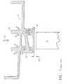
- Fig. 1 is a schematic illustration of a single stage active clearance control system of the type that may employ the casing mechanical deflection technique of the present invention;
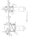
- Fig. 2 is a schematic illustration of a dual stage active clearance control system of the type that may employ the casing mechanical deflection technique of the present invention;
- Fig. 3 illustrates the thin case active clearance control according to the present invention;
- Fig. 4 is a diagram that shows the relation between pressure and rotor speed for idle to cruise conditions;
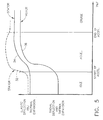
- Fig. 5 is a diagram comparing the radial deflection of the rotor and stator for a state of the art system and for the system applying the present invention; and
- Fig. 6 illustrates an alternative embodiment of the thin case active clearance control according to the present invention.
-
- Modern gas turbine engine control systems typically require an active clearance control system for maintaining blade-shroud clearances and tip clearances during operation. For a single and dual stage HPT, illustrated in Figs. 1 and 2, respectively, the
appropriate clearance 18 between theblade 14 and theshroud 16 is achieved by controlling thecase 10 temperature. For a single stage high-pressure turbine type, the case is heated and cooled by air coming from compressor mid stage 12 and discharge pressure source. Moreover, for a dual stage high-pressure turbine type, the first stage turbine case is controlled by compressor discharge pressure air. The second stage is controlled by compressor inter-stage bleed air. At appropriate times, the case is cooled by fan air in order to reducecase ring 25 temperatures. - In Figs. 1 and 2, the
blade 14 and blade tip rotate as a result of the hot air flowing through the turbine. Theshroud 16 is a piece of metal that defines the distances, or clearances, between theblade 14 tip and theshroud 16 itself. The purpose of the active clearance control system is to minimize-clearance 18. The larger the clearance, the less efficient the turbine will be. Theshroud 16 is attached to the case of the ACC by ahanger 22. Case growth causes theshroud 16 to move radially. In the existing art, thecase 10 grows only by thermal expansion. With the present invention, the case will deflect due to thermal expansion and pressure acting on the outer and inner diameter of the case. - The present invention proposes a system and method for improving an existing high-pressure turbine active clearance control system by modifying the turbine case, as illustrated in Fig. 3. In accordance with the present invention, the
elastic case 24 will be a continuous 360-degree shell flexible enough to deflect radially due to the difference between the pressures Plow acting on the outer diameter of thecase 24 and Phigh acting on the inner diameter of thecase 24. Thecase 24 flexibility will be achieved by making the case average thickness in the locations supporting the hangers thin, so that the casing elastic deflection is increased from the prior art design. Although the specific thickness can vary, in the prior art the thickness of the casing at the location where the shroud supports are attached to the casing will be substantially thicker than that proposed by the present invention, with the prior art configuration therefore having negligible casing deflection. In a preferred embodiment of the present invention, the thickness will be thinner than the current design by eliminating thecase rings 25, typically, by way of example only, on the order of approximately 0.1 inches to 0.2 inches, or otherwise significantly thinner than the 1 to 2 inch thickness of existing casings. It will be obvious to those skilled in the art, however, that the thickness can vary beyond the thickness of a preferred embodiment, still being thinner than the existing art provides for, without departing from the scope of the invention. As with existing systems, theshrouds 16 will be attached to thecase 24 byshroud hangers 22. The shroud and the case will be made of a high temperature alloy. - With the application of the present invention, the
blade 14 to shroud 16clearance 18 will change when thecase 24 deflects radially due to pressure. The blade tip to shroud clearance will depend on the magnitude of the pressure acting on the case. The pressure acting on the case depends on the engine operating condition. Referring now to Fig. 4 the relationship between pressure and speed is shown. The present invention takes advantage of this pressure and speed, resulting in the illustration of Fig. 5. In Fig. 4, the pressure is at a minimum when the engine is at idle conditions, inregion 26. It will reach a maximum during high power at low altitude, inregion 28. At cruise conditions, inregion 30, when the engine is at high altitudes, the pressure will decrease (∼30% change) while the speed remains almost constant (∼10% change). According to this relationship between pressure and speed, illustrated in Fig. 4, the clearance will increase when the engine goes from idle to take off conditions. This pressure to speed relationship will allow the system to compensate for some disk elastic stretch and blade thermal expansion without the necessity of having large clearance at idle. Moreover, at high altitudes the pressure acting on the case will decrease, causing the case to shrink while the rotor speed change is small, thus maintaining high elastic stretch. This will result in smaller clearance at cruise relative to clearances required by current state of the art systems. - The present invention takes advantage of the relationship between pressure and speed. Fig. 5 illustrates the stator and rotor deflection when the elastic case of the present invention is applied to a single or dual stage high pressure turbine. The elasticity of the case is indicated by
dotted line 32 in Fig. 5. The prior art stator response is shown byline 34, indicating the thermal expansion. The rotor response for both the invention and the prior art is shown byline 36, indicating disk elastic stretch and blade thermal expansion during periods of idle, acceleration and cruise. The present invention will provide a protection against airfoil to shroud contact due to instantaneous acceleration (reburst). The pressure will increase at nearly the same rate as the rotor speed during an instantaneous acceleration allowing the case to deflect to avoid airfoil to shroud contact (rubs). - Referring now to Fig. 6, an alternative embodiment for the thin case active clearance control can be applied by modifying the case elastic deflection to account for airfoil tip loss over operation time. The alternative embodiment comprises a
band 38 attached to the case outer diameter. The band is preferably comprised of any suitable high temperature alloy or coating. The band thickness will be sized depending on the amount of airfoil material loss. The band will cause the case elastic deflection to be less by the same amount of airfoil material loss.
Claims (10)
- A method of controlling clearance in a gas turbine engine, comprising the steps of:providing an active clearance control system acting on at least one blade (14) that rotates near at least one shroud (16), the at least one shroud (16) having an associated shroud hanger (22), wherein a clearance (18) is required between a tip of the at least one blade (14) and the at least one shroud (16); andsurrounding the blade (14) tip and shroud (16) with an elastic case (24), wherein the case (24) can deflect radially in response to thermal expansion and a difference in pressures acting on inner and outer diameters of the case (24).
- A method as claimed in claim 1 further comprising the step of attaching a band (38) to the case (24) outer diameter to account for blade (14) tip loss during operation.
- A method as claimed in claim 1 or 2 wherein the step of providing an active clearance control system further comprises the step of providing a single stage active clearance control system.
- A method as claimed in claim 1 or 2 wherein the step of providing an active clearance control system further comprises the step of providing a dual stage active clearance control system.
- A method as claimed in any preceding claim wherein the step of surrounding the blade (14) tip and shroud (16) with an elastic case (24) further comprises the step of providing an elastic case (24) having elastic deflection during engine operation.
- A system for controlling clearance in a gas turbine engine, comprising:an active clearance control system to act on at least one blade (14) that rotates near at least one shroud (16), the at least one shroud (16) having an associated shroud hanger (22), wherein a clearance (18) is required between a tip of the at least one blade (14) and the at least one shroud (16); andan elastic case (24) to surround the blade (14) tip and shroud (16), wherein the case (24) can deflect radially in response to a difference in pressures acting on inner and outer diameters of the case (24).
- A system as claimed in claim 6 further comprising a band (38) attached to the case (24) outer diameter to account for blade (14) tip loss during operation.
- A system as claimed in claim 6 or 7 wherein the active clearance control system comprises a single stage active clearance control system.
- A system as claimed in claim 6 or 7 wherein the active clearance control system comprises a dual stage active clearance control system.
- A system as claimed in any preceding claim wherein the elastic case (24) comprises an elastic case (24) having elastic deflection during engine operation.
Applications Claiming Priority (2)
| Application Number | Priority Date | Filing Date | Title |
|---|---|---|---|
| US10/428,219 US20040219011A1 (en) | 2003-05-02 | 2003-05-02 | High pressure turbine elastic clearance control system and method |
| US428219 | 2003-05-02 |
Publications (1)
| Publication Number | Publication Date |
|---|---|
| EP1475516A1 true EP1475516A1 (en) | 2004-11-10 |
Family
ID=32990469
Family Applications (1)
| Application Number | Title | Priority Date | Filing Date |
|---|---|---|---|
| EP04252521A Withdrawn EP1475516A1 (en) | 2003-05-02 | 2004-04-30 | High pressure turbine elastic clearance control system and method |
Country Status (4)
| Country | Link |
|---|---|
| US (1) | US20040219011A1 (en) |
| EP (1) | EP1475516A1 (en) |
| JP (1) | JP2004332731A (en) |
| CN (1) | CN1542259A (en) |
Cited By (9)
| Publication number | Priority date | Publication date | Assignee | Title |
|---|---|---|---|---|
| GB2418955A (en) * | 2004-07-09 | 2006-04-12 | United Technologies Corp | Blade tip clearance control |
| WO2006046969A2 (en) * | 2004-05-17 | 2006-05-04 | Cardarella L James Jr | Turbine case reinforcement in a gas turbine jet engine |
| WO2011026921A1 (en) | 2009-09-04 | 2011-03-10 | Turbomeca | Device for supporting a turbine ring, turbine having such a device, and turbine engine having such a turbine |
| FR2952965A1 (en) * | 2009-11-25 | 2011-05-27 | Snecma | INSULATING A CIRCONFERENTIAL SIDE OF AN EXTERNAL TURBOMACHINE CASTER WITH RESPECT TO A CORRESPONDING RING SECTOR |
| CN102352778A (en) * | 2011-10-20 | 2012-02-15 | 西北工业大学 | Electronic mechanical actuation device for actively controlling tip clearance of turbine |
| US8191254B2 (en) | 2004-09-23 | 2012-06-05 | Carlton Forge Works | Method and apparatus for improving fan case containment and heat resistance in a gas turbine jet engine |
| FR2973069A1 (en) * | 2011-03-24 | 2012-09-28 | Snecma | Ring for casing of stator of high pressure turbine, has part continuous on circumference and concentric with another part, and defining gas flow passage surrounded by casing, where former part is constructed by composite material |
| US8727709B2 (en) | 2009-09-28 | 2014-05-20 | Rolls-Royce Plc | Casing component |
| EP3351732A1 (en) * | 2017-01-18 | 2018-07-25 | United Technologies Corporation | Rotatable vanes |
Families Citing this family (23)
| Publication number | Priority date | Publication date | Assignee | Title |
|---|---|---|---|---|
| GB2404953A (en) * | 2003-08-15 | 2005-02-16 | Rolls Royce Plc | Blade tip clearance system |
| DE102004016222A1 (en) * | 2004-03-26 | 2005-10-06 | Rolls-Royce Deutschland Ltd & Co Kg | Arrangement for automatic running gap adjustment in a two-stage or multi-stage turbine |
| US8126628B2 (en) * | 2007-08-03 | 2012-02-28 | General Electric Company | Aircraft gas turbine engine blade tip clearance control |
| US8434997B2 (en) * | 2007-08-22 | 2013-05-07 | United Technologies Corporation | Gas turbine engine case for clearance control |
| FR2933458B1 (en) * | 2008-07-01 | 2010-09-03 | Snecma | AXIALO-CENTRIFUGAL COMPRESSOR WITH STEERING SYSTEM |
| CA2750938A1 (en) * | 2009-03-09 | 2010-09-16 | Snecma | Turbine ring assembly |
| US9726043B2 (en) | 2011-12-15 | 2017-08-08 | General Electric Company | Mounting apparatus for low-ductility turbine shroud |
| CA2912428C (en) | 2013-05-17 | 2018-03-13 | General Electric Company | Cmc shroud support system of a gas turbine |
| US9266618B2 (en) | 2013-11-18 | 2016-02-23 | Honeywell International Inc. | Gas turbine engine turbine blade tip active clearance control system and method |
| EP3080403B1 (en) * | 2013-12-12 | 2019-05-01 | General Electric Company | Cmc shroud support system |
| WO2015191169A1 (en) | 2014-06-12 | 2015-12-17 | General Electric Company | Shroud hanger assembly |
| CA2951638A1 (en) | 2014-06-12 | 2015-12-17 | General Electric Company | Shroud hanger assembly |
| JP6574208B2 (en) | 2014-06-12 | 2019-09-11 | ゼネラル・エレクトリック・カンパニイ | Shroud hanger assembly |
| US11008890B2 (en) * | 2014-11-25 | 2021-05-18 | Raytheon Technologies Corporation | Sealing interface for a case of a gas turbine engine |
| US9874104B2 (en) | 2015-02-27 | 2018-01-23 | General Electric Company | Method and system for a ceramic matrix composite shroud hanger assembly |
| US9915153B2 (en) * | 2015-05-11 | 2018-03-13 | General Electric Company | Turbine shroud segment assembly with expansion joints |
| FR3036432B1 (en) * | 2015-05-22 | 2019-04-19 | Safran Ceramics | TURBINE RING ASSEMBLY WITH AXIAL RETENTION |
| US10443417B2 (en) | 2015-09-18 | 2019-10-15 | General Electric Company | Ceramic matrix composite ring shroud retention methods-finger seals with stepped shroud interface |
| FR3041993B1 (en) * | 2015-10-05 | 2019-06-21 | Safran Aircraft Engines | TURBINE RING ASSEMBLY WITH AXIAL RETENTION |
| US10344769B2 (en) | 2016-07-18 | 2019-07-09 | United Technologies Corporation | Clearance control between rotating and stationary structures |
| EP3332894A1 (en) * | 2016-12-08 | 2018-06-13 | Siemens Aktiengesellschaft | Method for producing a gas turbine component |
| US10815816B2 (en) * | 2018-09-24 | 2020-10-27 | General Electric Company | Containment case active clearance control structure |
| KR102579798B1 (en) * | 2018-10-15 | 2023-09-15 | 한화에어로스페이스 주식회사 | Turbo Device |
Citations (8)
| Publication number | Priority date | Publication date | Assignee | Title |
|---|---|---|---|---|
| US4439982A (en) * | 1979-02-28 | 1984-04-03 | Mtu Motoren-Und Turbinen-Union Munchen Gmbh | Arrangement for maintaining clearances between a turbine rotor and casing |
| US4529355A (en) * | 1982-04-01 | 1985-07-16 | Rolls-Royce Limited | Compressor shrouds and shroud assemblies |
| US4683716A (en) * | 1985-01-22 | 1987-08-04 | Rolls-Royce Plc | Blade tip clearance control |
| US5407320A (en) * | 1991-04-02 | 1995-04-18 | Rolls-Royce, Plc | Turbine cowling having cooling air gap |
| US5593278A (en) * | 1982-12-31 | 1997-01-14 | Societe National D'etude Et De Construction De Moteurs D'aviation S.N.E.C.M.A. | Gas turbine engine rotor blading sealing device |
| EP1013894A2 (en) * | 1998-12-23 | 2000-06-28 | United Technologies Corporation | Fan case liner |
| US6116852A (en) * | 1997-12-11 | 2000-09-12 | Pratt & Whitney Canada Corp. | Turbine passive thermal valve for improved tip clearance control |
| US6126390A (en) * | 1997-12-19 | 2000-10-03 | Rolls-Royce Deutschland Gmbh | Passive clearance control system for a gas turbine |
Family Cites Families (6)
| Publication number | Priority date | Publication date | Assignee | Title |
|---|---|---|---|---|
| US3039737A (en) * | 1959-04-13 | 1962-06-19 | Int Harvester Co | Device for controlling clearance between rotor and shroud of a turbine |
| US4513567A (en) * | 1981-11-02 | 1985-04-30 | United Technologies Corporation | Gas turbine engine active clearance control |
| FR2540939A1 (en) * | 1983-02-10 | 1984-08-17 | Snecma | SEALING RING FOR A TURBINE ROTOR OF A TURBOMACHINE AND TURBOMACHINE INSTALLATION PROVIDED WITH SUCH RINGS |
| US4728255A (en) * | 1985-02-25 | 1988-03-01 | General Electric Company | Removable stiffening disk |
| US6487491B1 (en) * | 2001-11-21 | 2002-11-26 | United Technologies Corporation | System and method of controlling clearance between turbine engine blades and case based on engine components thermal growth model |
| GB2388407B (en) * | 2002-05-10 | 2005-10-26 | Rolls Royce Plc | Gas turbine blade tip clearance control structure |
-
2003
- 2003-05-02 US US10/428,219 patent/US20040219011A1/en not_active Abandoned
-
2004
- 2004-04-30 EP EP04252521A patent/EP1475516A1/en not_active Withdrawn
- 2004-04-30 JP JP2004135246A patent/JP2004332731A/en not_active Withdrawn
- 2004-04-30 CN CNA2004100421045A patent/CN1542259A/en active Pending
Patent Citations (8)
| Publication number | Priority date | Publication date | Assignee | Title |
|---|---|---|---|---|
| US4439982A (en) * | 1979-02-28 | 1984-04-03 | Mtu Motoren-Und Turbinen-Union Munchen Gmbh | Arrangement for maintaining clearances between a turbine rotor and casing |
| US4529355A (en) * | 1982-04-01 | 1985-07-16 | Rolls-Royce Limited | Compressor shrouds and shroud assemblies |
| US5593278A (en) * | 1982-12-31 | 1997-01-14 | Societe National D'etude Et De Construction De Moteurs D'aviation S.N.E.C.M.A. | Gas turbine engine rotor blading sealing device |
| US4683716A (en) * | 1985-01-22 | 1987-08-04 | Rolls-Royce Plc | Blade tip clearance control |
| US5407320A (en) * | 1991-04-02 | 1995-04-18 | Rolls-Royce, Plc | Turbine cowling having cooling air gap |
| US6116852A (en) * | 1997-12-11 | 2000-09-12 | Pratt & Whitney Canada Corp. | Turbine passive thermal valve for improved tip clearance control |
| US6126390A (en) * | 1997-12-19 | 2000-10-03 | Rolls-Royce Deutschland Gmbh | Passive clearance control system for a gas turbine |
| EP1013894A2 (en) * | 1998-12-23 | 2000-06-28 | United Technologies Corporation | Fan case liner |
Cited By (18)
| Publication number | Priority date | Publication date | Assignee | Title |
|---|---|---|---|---|
| WO2006046969A2 (en) * | 2004-05-17 | 2006-05-04 | Cardarella L James Jr | Turbine case reinforcement in a gas turbine jet engine |
| WO2006046969A3 (en) * | 2004-05-17 | 2006-06-22 | Cardarella L James Jr | Turbine case reinforcement in a gas turbine jet engine |
| EP2314831A1 (en) * | 2004-05-17 | 2011-04-27 | Carlton Forge Works | Turbine case reinforcement in a gas turbine jet engine |
| GB2418955B (en) * | 2004-07-09 | 2009-07-08 | United Technologies Corp | Blade clearance control |
| GB2418955A (en) * | 2004-07-09 | 2006-04-12 | United Technologies Corp | Blade tip clearance control |
| US8191254B2 (en) | 2004-09-23 | 2012-06-05 | Carlton Forge Works | Method and apparatus for improving fan case containment and heat resistance in a gas turbine jet engine |
| US8454298B2 (en) | 2004-09-23 | 2013-06-04 | Carlton Forge Works | Fan case reinforcement in a gas turbine jet engine |
| US8317456B2 (en) | 2004-09-23 | 2012-11-27 | Carlton Forge Works | Fan case reinforcement in a gas turbine jet engine |
| WO2011026921A1 (en) | 2009-09-04 | 2011-03-10 | Turbomeca | Device for supporting a turbine ring, turbine having such a device, and turbine engine having such a turbine |
| US8727709B2 (en) | 2009-09-28 | 2014-05-20 | Rolls-Royce Plc | Casing component |
| WO2011064496A1 (en) * | 2009-11-25 | 2011-06-03 | Snecma | Insulation of a circumferential edge of an outer casing of a turbine engine from a corresponding ring sector |
| FR2952965A1 (en) * | 2009-11-25 | 2011-05-27 | Snecma | INSULATING A CIRCONFERENTIAL SIDE OF AN EXTERNAL TURBOMACHINE CASTER WITH RESPECT TO A CORRESPONDING RING SECTOR |
| US8961117B2 (en) | 2009-11-25 | 2015-02-24 | Snecma | Insulating a circumferential rim of an outer casing of a turbine engine from a corresponding ring sector |
| FR2973069A1 (en) * | 2011-03-24 | 2012-09-28 | Snecma | Ring for casing of stator of high pressure turbine, has part continuous on circumference and concentric with another part, and defining gas flow passage surrounded by casing, where former part is constructed by composite material |
| CN102352778A (en) * | 2011-10-20 | 2012-02-15 | 西北工业大学 | Electronic mechanical actuation device for actively controlling tip clearance of turbine |
| CN102352778B (en) * | 2011-10-20 | 2013-11-27 | 西北工业大学 | Electronic mechanical actuation device for actively controlling tip clearance of turbine |
| EP3351732A1 (en) * | 2017-01-18 | 2018-07-25 | United Technologies Corporation | Rotatable vanes |
| US10968782B2 (en) | 2017-01-18 | 2021-04-06 | Raytheon Technologies Corporation | Rotatable vanes |
Also Published As
| Publication number | Publication date |
|---|---|
| CN1542259A (en) | 2004-11-03 |
| US20040219011A1 (en) | 2004-11-04 |
| JP2004332731A (en) | 2004-11-25 |
Similar Documents
| Publication | Publication Date | Title |
|---|---|---|
| EP1475516A1 (en) | High pressure turbine elastic clearance control system and method | |
| US9518474B2 (en) | Continuous ring composite turbine shroud | |
| JP5048444B2 (en) | Plasma blade tip clearance controller | |
| US5044881A (en) | Turbomachine clearance control | |
| JP3819424B2 (en) | Compressor vane assembly | |
| US7269955B2 (en) | Methods and apparatus for maintaining rotor assembly tip clearances | |
| US5645399A (en) | Gas turbine engine case coated with thermal barrier coating to control axial airfoil clearance | |
| JP2007315396A (en) | Method of compensating blade tip gap degrading in active gap control | |
| EP0781371A1 (en) | Dynamic control of tip clearance | |
| US5154575A (en) | Thermal blade tip clearance control for gas turbine engines | |
| US7654791B2 (en) | Apparatus and method for controlling a blade tip clearance for a compressor | |
| JP2006200530A (en) | Method and apparatus of maintaining tip clearance of rotor assembly | |
| US10822964B2 (en) | Blade outer air seal with non-linear response | |
| EP2009250B1 (en) | Annular turbine casing of a gas turbine engine and corresponding turbine assembly | |
| US6129513A (en) | Fluid seal | |
| US10082152B2 (en) | Gas turbine compressor with adaptive blade tip seal assembly | |
| EP2009251B1 (en) | Annular turbine casing of a gas turbine engine and corresponding turbine assembly | |
| JP3040560B2 (en) | Stator blade shroud integrated turbine | |
| EP3896263B1 (en) | Spoked thermal control ring for a high pressure compressor case clearance control system | |
| JP3959551B2 (en) | How to adjust wing tip clearance |
Legal Events
| Date | Code | Title | Description |
|---|---|---|---|
| PUAI | Public reference made under article 153(3) epc to a published international application that has entered the european phase |
Free format text: ORIGINAL CODE: 0009012 |
|
| AK | Designated contracting states |
Kind code of ref document: A1 Designated state(s): AT BE BG CH CY CZ DE DK EE ES FI FR GB GR HU IE IT LI LU MC NL PL PT RO SE SI SK TR |
|
| AX | Request for extension of the european patent |
Extension state: AL HR LT LV MK |
|
| 17P | Request for examination filed |
Effective date: 20050510 |
|
| AKX | Designation fees paid |
Designated state(s): DE FR GB |
|
| 17Q | First examination report despatched |
Effective date: 20060807 |
|
| STAA | Information on the status of an ep patent application or granted ep patent |
Free format text: STATUS: THE APPLICATION IS DEEMED TO BE WITHDRAWN |
|
| 18D | Application deemed to be withdrawn |
Effective date: 20081202 |