EP1475302A1 - Electronically servo-assisted bicycle gearshift - Google Patents
Electronically servo-assisted bicycle gearshift Download PDFInfo
- Publication number
- EP1475302A1 EP1475302A1 EP03425287A EP03425287A EP1475302A1 EP 1475302 A1 EP1475302 A1 EP 1475302A1 EP 03425287 A EP03425287 A EP 03425287A EP 03425287 A EP03425287 A EP 03425287A EP 1475302 A1 EP1475302 A1 EP 1475302A1
- Authority
- EP
- European Patent Office
- Prior art keywords
- sprocket
- gear
- gearshift
- shifting
- displacement
- Prior art date
- Legal status (The legal status is an assumption and is not a legal conclusion. Google has not performed a legal analysis and makes no representation as to the accuracy of the status listed.)
- Granted
Links
- 238000000034 method Methods 0.000 claims abstract description 36
- 238000006073 displacement reaction Methods 0.000 claims abstract description 18
- 230000015654 memory Effects 0.000 claims description 95
- 238000012544 monitoring process Methods 0.000 claims description 18
- 238000005516 engineering process Methods 0.000 claims description 4
- 229910000831 Steel Inorganic materials 0.000 description 6
- 239000010959 steel Substances 0.000 description 6
- 230000003213 activating effect Effects 0.000 description 4
- 238000010586 diagram Methods 0.000 description 4
- 230000033001 locomotion Effects 0.000 description 4
- 238000010276 construction Methods 0.000 description 2
- 230000005540 biological transmission Effects 0.000 description 1
- 239000003638 chemical reducing agent Substances 0.000 description 1
- 125000004122 cyclic group Chemical group 0.000 description 1
- 230000003247 decreasing effect Effects 0.000 description 1
- 230000001419 dependent effect Effects 0.000 description 1
- 230000035622 drinking Effects 0.000 description 1
- 230000006870 function Effects 0.000 description 1
- 230000002401 inhibitory effect Effects 0.000 description 1
- 230000003287 optical effect Effects 0.000 description 1
- 230000001737 promoting effect Effects 0.000 description 1
Images




Classifications
-
- B—PERFORMING OPERATIONS; TRANSPORTING
- B62—LAND VEHICLES FOR TRAVELLING OTHERWISE THAN ON RAILS
- B62M—RIDER PROPULSION OF WHEELED VEHICLES OR SLEDGES; POWERED PROPULSION OF SLEDGES OR SINGLE-TRACK CYCLES; TRANSMISSIONS SPECIALLY ADAPTED FOR SUCH VEHICLES
- B62M9/00—Transmissions characterised by use of an endless chain, belt, or the like
- B62M9/04—Transmissions characterised by use of an endless chain, belt, or the like of changeable ratio
- B62M9/06—Transmissions characterised by use of an endless chain, belt, or the like of changeable ratio using a single chain, belt, or the like
- B62M9/10—Transmissions characterised by use of an endless chain, belt, or the like of changeable ratio using a single chain, belt, or the like involving different-sized wheels, e.g. rear sprocket chain wheels selectively engaged by the chain, belt, or the like
- B62M9/12—Transmissions characterised by use of an endless chain, belt, or the like of changeable ratio using a single chain, belt, or the like involving different-sized wheels, e.g. rear sprocket chain wheels selectively engaged by the chain, belt, or the like the chain, belt, or the like being laterally shiftable, e.g. using a rear derailleur
- B62M9/121—Rear derailleurs
- B62M9/122—Rear derailleurs electrically or fluid actuated; Controls thereof
-
- B—PERFORMING OPERATIONS; TRANSPORTING
- B62—LAND VEHICLES FOR TRAVELLING OTHERWISE THAN ON RAILS
- B62M—RIDER PROPULSION OF WHEELED VEHICLES OR SLEDGES; POWERED PROPULSION OF SLEDGES OR SINGLE-TRACK CYCLES; TRANSMISSIONS SPECIALLY ADAPTED FOR SUCH VEHICLES
- B62M25/00—Actuators for gearing speed-change mechanisms specially adapted for cycles
- B62M25/08—Actuators for gearing speed-change mechanisms specially adapted for cycles with electrical or fluid transmitting systems
-
- B—PERFORMING OPERATIONS; TRANSPORTING
- B62—LAND VEHICLES FOR TRAVELLING OTHERWISE THAN ON RAILS
- B62M—RIDER PROPULSION OF WHEELED VEHICLES OR SLEDGES; POWERED PROPULSION OF SLEDGES OR SINGLE-TRACK CYCLES; TRANSMISSIONS SPECIALLY ADAPTED FOR SUCH VEHICLES
- B62M9/00—Transmissions characterised by use of an endless chain, belt, or the like
- B62M9/04—Transmissions characterised by use of an endless chain, belt, or the like of changeable ratio
- B62M9/06—Transmissions characterised by use of an endless chain, belt, or the like of changeable ratio using a single chain, belt, or the like
- B62M9/10—Transmissions characterised by use of an endless chain, belt, or the like of changeable ratio using a single chain, belt, or the like involving different-sized wheels, e.g. rear sprocket chain wheels selectively engaged by the chain, belt, or the like
- B62M9/12—Transmissions characterised by use of an endless chain, belt, or the like of changeable ratio using a single chain, belt, or the like involving different-sized wheels, e.g. rear sprocket chain wheels selectively engaged by the chain, belt, or the like the chain, belt, or the like being laterally shiftable, e.g. using a rear derailleur
- B62M9/131—Front derailleurs
- B62M9/132—Front derailleurs electrically or fluid actuated; Controls thereof
-
- Y—GENERAL TAGGING OF NEW TECHNOLOGICAL DEVELOPMENTS; GENERAL TAGGING OF CROSS-SECTIONAL TECHNOLOGIES SPANNING OVER SEVERAL SECTIONS OF THE IPC; TECHNICAL SUBJECTS COVERED BY FORMER USPC CROSS-REFERENCE ART COLLECTIONS [XRACs] AND DIGESTS
- Y10—TECHNICAL SUBJECTS COVERED BY FORMER USPC
- Y10T—TECHNICAL SUBJECTS COVERED BY FORMER US CLASSIFICATION
- Y10T74/00—Machine element or mechanism
- Y10T74/18—Mechanical movements
- Y10T74/18568—Reciprocating or oscillating to or from alternating rotary
- Y10T74/18832—Reciprocating or oscillating to or from alternating rotary including flexible drive connector [e.g., belt, chain, strand, etc.]
-
- Y—GENERAL TAGGING OF NEW TECHNOLOGICAL DEVELOPMENTS; GENERAL TAGGING OF CROSS-SECTIONAL TECHNOLOGIES SPANNING OVER SEVERAL SECTIONS OF THE IPC; TECHNICAL SUBJECTS COVERED BY FORMER USPC CROSS-REFERENCE ART COLLECTIONS [XRACs] AND DIGESTS
- Y10—TECHNICAL SUBJECTS COVERED BY FORMER USPC
- Y10T—TECHNICAL SUBJECTS COVERED BY FORMER US CLASSIFICATION
- Y10T74/00—Machine element or mechanism
- Y10T74/18—Mechanical movements
- Y10T74/18568—Reciprocating or oscillating to or from alternating rotary
- Y10T74/18832—Reciprocating or oscillating to or from alternating rotary including flexible drive connector [e.g., belt, chain, strand, etc.]
- Y10T74/1884—Reciprocating or oscillating to or from alternating rotary including flexible drive connector [e.g., belt, chain, strand, etc.] with sprocket wheel
-
- Y—GENERAL TAGGING OF NEW TECHNOLOGICAL DEVELOPMENTS; GENERAL TAGGING OF CROSS-SECTIONAL TECHNOLOGIES SPANNING OVER SEVERAL SECTIONS OF THE IPC; TECHNICAL SUBJECTS COVERED BY FORMER USPC CROSS-REFERENCE ART COLLECTIONS [XRACs] AND DIGESTS
- Y10—TECHNICAL SUBJECTS COVERED BY FORMER USPC
- Y10T—TECHNICAL SUBJECTS COVERED BY FORMER US CLASSIFICATION
- Y10T74/00—Machine element or mechanism
- Y10T74/20—Control lever and linkage systems
- Y10T74/20396—Hand operated
- Y10T74/20402—Flexible transmitter [e.g., Bowden cable]
- Y10T74/2042—Flexible transmitter [e.g., Bowden cable] and hand operator
- Y10T74/20438—Single rotatable lever [e.g., for bicycle brake or derailleur]
Definitions
- the present invention concerns an electronically servo-assisted bicycle gearshift and a method for servo-assisting a bicycle gearshift, as well as a program and an electronic circuit having means for carrying out the method.
- An electronically servo-assisted bicycle gearshift generally comprises:
- EP 1 103 456 describes a gearshift wherein the position transducers are of the absolute type, capable of providing an electrical signal indicating the absolute position of the derailleurs, so that after switching them on (again), such transducers take into account the actual position of the derailleurs, which could be slightly displaced due, for example, to vibrations caused by the travel of the bicycle.
- the rear actuator or front actuator must therefore be displaced in a position typically beyond the position corresponding to the second sprocket.
- the problem is particularly serious in the case of the front gearshift, where the chain is taut.
- Such a displacement in advanced position with respect to the second sprocket acts promoting the release of the chain from engagement with the first sprocket and the engagement of the chain on the second sprocket.
- a control mechanism comprising a steel cable slidably extending in a sheath ("Bowden cable") between a manual actuation lever and the chain guide element.
- Bowden cable a steel cable slidably extending in a sheath
- the actuation of the lever in a first direction applies a traction on the chain guide element through the steel cable
- the actuation of the lever in a second opposite direction applies a thrust on the chain guide element through the steel cable, or lets the cable and the chain guide element free to be returned by a return spring.
- a control system has been implemented in which the actuation of the lever causes a movement of the steel cable of such a length that the chain guide element displaces for a greater length than that necessary to reach the position of the adjacent sprocket.
- the return spring acts to take the steel cable - and thus the chain guide element - back to the position corresponding to the second sprocket.
- the actuation of the control lever causes a temporary displacement of the chain guide element greater than the pitch between two adjacent sprockets of the gearshift group by a certain amount indicated hereafter as "overstroke".
- Such a mechanical control gearshift requires a periodical and relatively precise mechanical adjustment of the steel cable and of the tension of the return spring.
- this mechanical solution has the drawback that it is possible to adjust the amount of the overstroke to a single value, which impacts as much in all of the upwards gear-shiftings as in all of the downwards gear-shiftings. Consequently, when the amount of the overstroke in a gearshift group is adjusted for an optimal gear-shifting in one direction (for example for upwards gear-shiftings), a gear-shifting in the opposite direction (in the example, downwards) is totally unsatisfactory. Alternatively it is necessary to adjust the amount of the overstroke to an intermediate value, obtaining sufficient but not optimal results in gear-shiftings in both directions.
- the object of the invention is to provide an electronically servo-assisted gearshift that allows optimal gear-shifting in both directions, up and down, and between any pair of sprockets.
- the present invention concerns a method for electronically servo-assisting an electronically servo-assisted bicycle gearshift, comprising the steps of:
- the upwards gear-shifting position for the second sprocket and the downwards gear-shifting position for the second sprocket are asymmetrical with respect to a theoretical position of the second sprocket.
- the step b1) of obtaining an upwards gear-shifting position for the second sprocket may comprise the step of obtaining a theoretical position of the second sprocket.
- the step b1) of obtaining an upwards gear-shifting position for the second sprocket may also comprise the step of algebraically adding a predetermined amount of overstroke to the theoretical position of the second sprocket.
- the step b2) of obtaining a downwards gear-shifting position for the second sprocket may comprise the step of obtaining a theoretical position of the second sprocket.
- the step b2) of obtaining a downwards gear-shifting position for the second sprocket may also comprise the step of algebraically adding a predetermined amount of overstroke to the theoretical position of the second sprocket.
- the method may also comprise the sequential steps of:
- the step c1) of temporarily maintaining the position comprises the step of waiting a predetermined time period.
- the step c1) of temporarily maintaining the position comprises the step of waiting for an end-of-displacement-request signal.
- the step c1) of temporarily maintaining the position comprises the sequential steps of waiting a predetermined minimum time period, and waiting for an end-of-displacement-request signal.
- the step c1) of temporarily maintaining the position comprises the steps of monitoring the passing of a predetermined minimum time period, and monitoring the receiving of an end-of-displacement-request signal, wherein the execution of step d) takes place at the latest in time between the receiving of the end-of-displacement-request signal and the passing of the predetermined minimum time period.
- the step c1) of temporarily maintaining the position comprises the steps of monitoring the receiving of an end-of-displacement-request signal, and monitoring the passing of a predetermined maximum time period, wherein the execution of step d) takes place at the first in time between the receiving of the end-of-displacement-request signal and the passing of the predetermined maximum time period.
- the step c1) of temporarily maintaining the position comprises the steps of monitoring the passing of a predetermined minimum time period, monitoring the receiving of an end-of-displacement-request signal, and monitoring the passing of a predetermined maximum time period, wherein the execution of step d) takes place at the latest in time between the receiving of the end-of-displacement-request signal and the passing of the predetermined minimum time period if the receiving of the end-of-displacement-request signal precedes in time the passing of the predetermined maximum time period, or else upon the passing of the predetermined maximum time period if it precedes the receiving of the end-of-displacement-request signal.
- the method according to the invention advantageously comprises the step of setting a value of said or of each of said gear-shifting positions or of said or of each of said amounts of overstroke and/or of said or of each of said predetermined time periods.
- the invention concerns a program for electronically servo-assisting a bicycle gearshift, comprising program code means suitable for carrying out the steps of the above described method when the program is run on a computer.
- the program is preferably embodied in at least one microcontroller.
- the program can be stored in a computer memory or embodied in a read-only memory.
- the invention concerns an electronic circuit suitable for carrying out the steps of the above described method.
- the invention concerns a bicycle gearshift, comprising:
- the electronic control unit may comprise means for checking at least one condition selected from the group consisting of the passing of a predetermined time period and the receiving of an end-of-displacement-request signal and, subordinately to said checking means, be suitable for driving the rear or front actuator to displace the guide element of the chain from the upwards gear-shifting position for the second sprocket or, respectively, from the downwards gear-shifting position for the second sprocket to a theoretical position of the second sprocket.
- the electronic control unit may comprise memory means suitable for storing the upwards gear-shifting position and/or the downwards gear-shifting position for at least one second sprocket.
- the electronic control unit may comprise memory means suitable for storing at least one differential amount representing the difference between the theoretical position of at least one sprocket and the upwards gear-shifting position or, respectively, the downwards gear-shifting position for said at least one sprocket.
- the electronic control unit may also comprise memory means suitable for storing information representing the theoretical position of each sprocket.
- the gearshift comprises a rear counter and a front counter indicating the position of the guide element of the chain with respect to the rear and front gearshift group, respectively.
- the gearshift according to the invention may comprise means for detecting the position of the rear actuator and front actuator, respectively, and providing it to the electronic control unit, comprising a rear transducer and a front transducer.
- the electronic control unit may drive the rear or front actuator, respectively, in a feedback controlled manner by the position detected by the means for detecting the position.
- the motors of the rear and front actuators can be stepper motors and a displacement of the rear or front actuator by one step or by an integer multiple of steps corresponds to a unitary increase or decrease of the rear or front counter.
- the motors of the front and rear actuators can be selected from the group consisting of dc motors, brushless motors, asynchronous motors and hydraulic motors.
- the gearshift typically may comprise a power board arranged between the electronic control unit and the rear and front actuators.
- the electronic control unit may comprise at least one micro-controller made in C-MOS technology.
- the electronic control unit is distributed and comprises many microcontrollers at a display unit and/or at a unit controlling manual input means and/or at a power board.
- the display unit is preferably removable.
- a bicycle in particular a racing bicycle, includes a frame 2 formed in a known way from tubular elements defining a support structure 3 for a rear wheel 4 and a fork 5 for a front wheel 6.
- a handlebar 70 having a tubular structure is operatively connected to the fork 5.
- the frame 2 at its lower portion, supports an axle of the pedal cranks or pedal unit 7, of the conventional type, to actuate the rear wheel 4 through an electronically servo-assisted gearshift according to the invention, generally indicated with reference 8.
- the gearshift 8 is substantially formed from a rear gearshift group 9 and a front gearshift group 10.
- the rear gearshift group 9 includes a plurality of toothed wheels or sprockets or pinions 11 (ten in the illustrated example, but which can also be nine, eleven or whatever else in number) having different diameters and coaxial (axis A) with the rear wheel 4.
- the front gearshift group 10 includes a plurality of toothed wheels or sprockets or crowns or gears 12 (three in the illustrated example, but which can also be two or whatever else in number), having different diameters and coaxial (axis B) with the axle of the pedal cranks 7.
- the sprockets 11 of the rear gearshift group 9 and the sprockets 12 of the front gearshift group 10 are selectively engageable by a looped transmission chain 13, to provide the different available gear ratios, through the electronically servo-assisted gearshift 8.
- the different gear ratios can be obtained by moving a chain guide element or rear derailleur (or also simply gearshift) 14 of the rear gearshift group 9 and/or a chain guide element or front derailleur (or also simply derailleur) 15 of the front gearshift group 10.
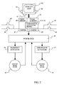
- the rear derailleur 14 and the front derailleur 15 are controlled by a respective actuator 16, 17 ( Figure 2) typically comprising an articulated parallelogram mechanism and an electric motor with reducer to deform the articulated parallelogram.
- a position sensor of the rear derailleur or rear transducer 18 and a position sensor of the front derailleur or front transducer 19 ( Figure 2) are associated with the actuators 16, 17.
- transducers 18, 19 are preferably of the type described in EP 1 103 456 A2, suitable for providing an electrical signal indicating the absolute position of the derailleurs 14, 15.
- the battery is preferably of the rechargeable type and the rear derailleur 14 can include, in a per se known way, a dynamo-electric unit for recharging the battery.
- a logic unit shall be meant, which can however be formed of many physical units, in particular of one or more distributed microprocessors which can be held in the display unit 60 and/or in the electronic power board 30 and/or in a command unit.
- the electronic control unit 40 comprises, besides the microprocessor(s), memory means which can comprise one or more device(s) for storing the instructions which encode the management program of the electronic gearshift, for the temporary storing of service variables to carry out the program itself (registers) as well as for volatile, non-volatile or permanent storing of some values specified later in the description.
- the memory means are distinct in rear memory means, front memory means, overstroke memory means and gear-shifting memory means. It must however be clear that such a distinction is simply to be taken from the functional point of view and does not necessarily have to correspond to a physical distinction of the storing devices.
- one or more physical devices can be used for each of the memory means indicated above or, vice-versa, each of the memory means indicated above can physically be embodied by a respective physical device or by memory locations of one or more physical devices.
- the storing devices can be of one or more types among read only, write once, or read/write, random access or sequential access memories, and they can be made in various technologies, such as optical memories, magnetic memories, etc.
- the storing device(s) can be contained in the display unit 60 and/or in the electronic power board 30 and/or in the command unit and/or they can be distinct devices.
- the display unit 60 can be removed from the bicycle 1 and houses at least part of the memory means of the electronic control unit 40.
- the values set by the user for various parameters of the electronically servo-assisted gearshift 8 are preferably stored in the memory means housed in the display unit 60.
- the electronic power board 30 is, for example, housed in one of the tubes of the handlebar 70, in one of the tubes of the frame 2, for example at a support for a drinking bottle (not illustrated), or in the display unit 60, which is preferably housed centrally on the handlebar 70.
- the information transfer between the various components is carried out through electrical cables, advantageously housed inside the tubes of the frame 2, or else in a wireless mode, for example with the Bluetooth protocol.
- the rear and front deraille 14, 15 are controlled, through the actuators 16, 17, by the electronic control unit 40 based upon signals requesting a displacement of the chain towards a sprocket adjacent to the one upon which the chain is engaged (upwards and downwards gear-shifting request signals) established by manual command devices, or semi-automatically or automatically by the electronic control unit 40 itself.
- the manual command devices can, for example, comprise levers 43, 44 associated with the brake lever 41 on a grip of the handlebar 70 for the upwards and downwards gear-shifting signals, respectively, of the rear gearshift group 9, and levers 45, 46 (Figure 2) associated with the brake lever on the other grip of the handlebar 70 for the upwards or downwards gear-shifting signals of the front gearshift group 10 (the levers 45, 46 are not illustrated in Figure 1 for the sake of clarity).
- buttons 43, 44 45, 46
- two manually operated buttons or two buttons which can be operated by a swing lever can be provided.
- the electronic control unit 40 is also associated with the two transducers 18, 19 to stop the motors of the actuators 16, 17 when the respective derailleur 14 or 15 has reached the desired position, such that the chain can engage the adjacent sprocket 11 or 12 (with a larger or smaller diameter, respectively) to the one with which it was engaged when the displacement request signal (upwards or downwards gear-shifting request signal, respectively) was generated through the manual command device 43, 44, 45, 46 or by the electronic control unit 40.
- Such a position is indicated in the present description and in the attached claims as "gear-shifting position".
- the gear-shifting position for at least one given sprocket 11, 12 of a gearshift group 9, 10 is preferably different according to whether the gear-shifting is upwards or downwards and more preferably the upwards and downwards gear-shifting positions are asymmetrical with respect to the theoretical position of the sprocket.
- the motors of the actuators 16, 17 are stepper motors which are driven by an appropriate number of steps for each upwards or downwards gear-shifting and then automatically stopped, whereas the transducers 18, 19 are used to provide a feedback signal to the electronic control unit 40 so that it can possibly provide to actuate once again the motors of the actuators 16, 17 in case the gear-shifting position has not been reached.
- This can, for example, be due to the fact that the resisting torque offered by the derailleur 14, 15, which is to some degree dependent upon how the rider is pedalling, was too high, greater than the maximum torque which can be delivered by the stepper motors.
- the electronic control unit 40 comprises a rear counter 47 and a front counter 48.
- the counters 47, 48 can, for example, each be embodied by a register or a variable stored in a memory cell of the electronic control unit.
- the electronic control unit 40 in the normal ride operating mode of the gearshift 8, drives the actuators 16, 17 and tracks their position increasing or decreasing the counters 47, 48, for example by one unit for every step imposed on the stepper motor and/or based upon the reading of the transducers 18, 19.
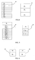
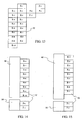
- the memory means of the electronic control unit 40 comprise (figures 4-6, described hereafter) rear memory means 49 for the theoretical positions of the sprockets 11 of the rear gearshift group 9 and front memory means 50 for the theoretical positions of the sprockets 12 of the front gearshift group 10.
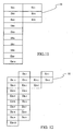
- the memory means of the electronic control unit 40 also comprise overstroke memory means 51 (figures 7-12, described hereafter) for at least a differential amount, indicated as "amount of overstroke".
- the or each amount of overstroke represents the offset between the theoretical position of the sprocket 11 and/or 12, indicated by the memory means 49 and/or 50, and the position that the guide element 14, 15 of the chain 13 must take up during an upwards and/or downwards gear-shifting to assist the gear-shifting itself, i.e. the upwards and/or downwards gear-shifting position defined above.
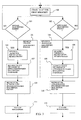
- FIG. 3 represents a method according to the invention for electronically servo-assisting the gearshift 8 and which generally applies both to the rear gearshift group 9 and to the front gearshift group 10, if the chain 13 is, block 100, at a first sprocket 11 (12) and the counter 47 (48) has a first logic value, when the rider actuates the manual upwards gear-shifting request command 43 (45), block 101, or respectively, the manual downwards gear-shifting request control 44 (46), block 102 (or when such a request is generated by the electronic control unit 40 itself), the electronic control unit 40 firstly provides for obtaining the gear-shifting position for the second sprocket 11 (12), block 103 or 104 respectively, which according to the present invention shall be an upwards gear-shifting position, if the first sprocket has a smaller diameter than the second sprocket (block 103), and a downwards gear-shifting position, if the first sprocket has a larger diameter than the second
- the electronic control unit 40 takes care of driving, block 109 or 110, respectively, the actuator 16 (17) to displace the chain along the axis A (B) in a first direction which goes from the first sprocket to the second sprocket until the counter 47 (48) reaches the value indicated by the upwards gear-shifting position or by the downwards gear-shifting position, respectively.
- actuators 16, 17 comprise stepper motors, advantageously a movement of one step or an integer multiple of steps of the stepper motor, in a first or second direction of rotation, corresponds to each unitary increase or decrease of the counter 47, 48.
- the electronic control unit 40 can optionally take care of carrying out a stay and repositioning step, schematically indicated by the dashed blocks 111 and 112 in figure 3 and better described hereafter with reference to figures 16-19.
- a stay and repositioning step comprises driving the actuator 16 (17) to displace the chain along the axis A (B) in the first direction or in a second direction opposite to the first direction until the counter 47 (48) reaches the theoretical position of the second sprocket 11 (12), read directly from the memory means 49 (50) or derived from the information read from the memory means 49 (50).
- the step of obtaining the upwards gear-shifting position (block 103), or respectively the downwards gear-shifting position (block 104), is carried out through the steps of:
- the rear and front memory means 49 and 50 are suitable for directly storing a value associated with each sprocket 11, 12 of the respective gearshift group 9, 10, representing the physical position of the sprocket 11, 12 in the respective gearshift group.
- the rear memory means 49 are suitable for storing a logic value R1 associated with the wheel with the smallest diameter, a logic value R2 associated with the sprocket immediately adjacent to it, with a slightly larger diameter, a logic value R3 associated with the sprocket immediately adjacent to it, with a yet larger diameter etc., up to a logic value R10 associated with the sprocket with the largest diameter;
- the front memory means 50 are suitable for storing a logic value F1 associated with the wheel with the smallest diameter, a logic value F2 associated with the sprocket with an intermediate diameter and a logic value F3 associated with the sprocket with the largest diameter.
- the electronic control unit 40 obtains, in block 105 or 106, the theoretical position of the second sprocket 11, 12 by reading the value associated with it directly from the memory 49, 50.
- the rear memory means 49 are suitable for storing a differential amount associated with each pair of adjacent sprockets 11.
- the rear memory means 49 are suitable for storing a differential amount ⁇ R1-2 associated with the pair consisting of the sprocket 11 with the smallest diameter and the sprocket 11 immediately adjacent to it (with a slightly larger diameter), a differential amount ⁇ R2-3 associated with the pair consisting of this latter sprocket and that one adjacent to it, etc., up to a differential amount ⁇ R9-10 associated with the pair of sprockets 11 having the largest diameters;
- the front memory means 50 are suitable for storing two differential amount ⁇ F1-2 and ⁇ F2-3. If the theoretical position of the sprocket with the smallest diameter does not correspond
- the electronic control unit 40 obtains, in block 105 (or in block 106 respectively), the theoretical position of the second sprocket 11, 12 by adding (or subtracting) the differential amount corresponding to the pair consisting of the first sprocket 11, 12 and the second sprocket 11, 12 with immediately larger (smaller) diameter stored in the front and rear memory means 49, 50 to (or from) the current value of the counter when the chain 13 is at the first sprocket, block 100.
- the electronic control unit 40 obtains, in block 105 (or in block 106, respectively), the theoretical position of the second sprocket 11, 12 by adding up the differential amount associated with the pair of sprockets formed by the second sprocket and the adjacent sprocket with a smaller diameter (which is the first sprocket in the case of an upwards gear-shifting), all of the possible differential amounts associated with the pairs of sprockets with smaller diameters and the value associated with the sprocket with the smallest diameter, if provided for.
- the rear 49 and front memory means 50 are suitable for storing a single differential amount ⁇ R and ⁇ F. If the pitch between adjacent sprockets 11 of the rear gearshift group 9 is equal to the pitch between adjacent sprockets 12 of the front gearshift group 10, there can be only a single memory means, for example just the front memory 49. If the theoretical position of the sprocket with the smallest diameter does not correspond to the zero value of the counter 47, 48, the front and rear memory means 49, 50 are also suitable for storing such a theoretical position R1, F1.
- the electronic control unit 40 obtains, in block 105 (or in block 106, respectively), the theoretical position of the second sprocket 11, 12 by adding (or subtracting) the differential amount ⁇ R or ⁇ F to or from the current value of the counter when the chain 13 is at the first sprocket, block 100.
- the electronic control unit 40 obtains the theoretical position of the second sprocket 11, 12 from the product of the differential amount ⁇ R or ⁇ F times the number (j-1 if the second sprocket is the j th of the gearshift group) of pairs of sprockets comprised of the pair of sprockets formed by the second sprocket and by the adjacent sprocket with a smaller diameter (which is the first sprocket in the case of an upwards gear-shifting) and all of the possible differential amounts associated with the pairs of sprockets with smaller diameters and adding to this, if provided for, the value associated with the sprocket with the smallest diameter.
- the electronic control unit 40 can use the single amount of overstroke E in various ways according to the block diagram of figure 3.
- such an amount of overstroke E is algebraically added in the case of an upwards gear-shifting, block 107, to the theoretical position of the second sprocket obtained in block 105 in the ways defined above, whereas block 108 is absent; in such a case the amount of overstroke E is typically represented by a positive number.
- the amount of overstroke E, as well as the theoretical position of the second sprocket 11, 12 stored directly or indirectly in the rear and front memory means 49, 50 and obtained in block 105 or 106, shall have suitable values according to the way of use by the electronic control unit 40; typically, in the second and third ways the theoretical position of the second sprocket can be corrected with respect to the physical position of the sprocket itself.
- the overstroke memory means 51 are suitable for storing an amount E+ of overstroke for an upwards gear-shifting and an amount E- of overstroke for a downwards gear-shifting, in general represented by relative numbers. More typically, the amount E+ of overstroke for an upwards gear-shifting is represented by a positive number and the amount of overstroke E- for a downwards gear-shifting is represented by a negative number.
- the electronic control unit 40 in block 107 of figure 3, algebraically adds the amount of overstroke E+ for an upwards gear-shifting to the theoretical position of the second sprocket 11, 12 obtained in the step represented by block 105; in the case of a downwards gear-shifting, the electronic control unit 40, in block 108, algebraically adds the amount of overstroke E- for a downwards gear-shifting to the theoretical position of the second sprocket 11, 12 obtained in the step represented by block 106.
- the overstroke memory means 51 are suitable for storing a single amount of overstroke ER for the rear gearshift group 9 and a single amount of overstroke EF for the front gearshift group 10, each independently used by the electronic control unit 40 in one of the three ways outlined above with reference to the embodiment of figure 7 and to which the other considerations outlined with reference to such a figure 7 apply.
- the overstroke means 51 are suitable for storing, for the rear gearshift group 9, an amount ER+ of overstroke for an upwards gear-shifting and an amount ER- of overstroke for a downwards gear-shifting and, for the front gearshift group 10, an amount EF+ of overstroke for an upwards gear-shifting and an amount EF- of overstroke for a downwards gear-shifting, to be used in the way described above with reference to the embodiment of figure 8.
- the amounts of overstroke according to the fourth embodiment ER+, ER-, EF+, EF- are also generally represented by relative numbers, but typically the amounts ER+, EF+ are represented by positive numbers so that their absolute value is added to the theoretical position of the second sprocket 11, 12, whereas the amounts ER-, EF- are represented by negative numbers so that their absolute value is subtracted from the theoretical position of the second sprocket 11, 12. This is because, to assist the gear-shifting from a first sprocket to a second sprocket, it turns out to be suitable to displace the chain guide element 14, 15 in a gear-shifting position far from the first sprocket beyond the second sprocket.
- the overstroke memory means are suitable for storing an amount ERj of overstroke for each sprocket of the rear gearshift group 9 and an amount EFj of overstroke for each sprocket of the front gearshift group 10.
- the amounts of overstroke ERj, EFj can be managed by the electronic control unit 40 in block 107 and/or in block 108 in the three ways described above with reference to the embodiment of figure 7.
- the first way in which in the case of an upwards gear-shifting the amount of overstroke ERj or EFj associated with the second sprocket is algebraically added, in particular added in an absolute value, to the theoretical position of the second sprocket, whereas block 108 is absent, no amount of overstroke associated with the sprocket with the smallest diameter shall be provided for;
- the second way in which in the case of a downwards gear-shifting the amount of overstroke ERj or EFj associated with the second sprocket is algebraically added, in particular subtracted in an absolute value, to the theoretical position of the second sprocket, whereas block 107 is absent, no amount of overstroke associated with the sprocket with the largest diameter shall be provided for.
- the overstroke memory means are suitable for storing an amount of overstroke for an upwards gear-shifting ER+j, EF+j and an amount of overstroke for a downwards gear-shifting ER-j, EF-j for each intermediate sprocket 11, 12 of each gearshift group 9, 10, as well as an amount of overstroke for an upwards gear-shifting ER+j, EF+j for the sprocket with the largest diameter and an amount of overstroke for a downwards gear-shifting ER-1, EF-1 for the sprocket with the smallest diameter.
- an amount of overstroke for an upwards gear-shifting and an amount of overstroke for a downwards gear-shifting are stored for each pair of adjacent sprockets of each gearshift group.
- rear gearshift group 9 having ten sprockets 11 eighteen amounts shall be provided for and in the case of front gearshift group 10 comprising three sprockets 12, four amounts shall be provided for.
- the electronic control unit 40 algebraically adds the amount of overstroke ER+j, EF+j for an upwards gear-shifting associated with the second sprocket to the theoretical position of the second sprocket 11, 12; in the case of a downwards gear-shifting, the electronic control unit 40, in block 108, algebraically adds the amount of overstroke ER-j, EF-j for a downwards gear-shifting associated with the second sprocket to the theoretical position of the second sprocket 11, 12.
- the upwards gear-shifting position obtained in block 103 is generally different from the downwards gear-shifting position obtained in block 104, because it is obtained through a different application of a same absolute overstroke value in the aforementioned two blocks, because it is obtained through the application of the or an overstroke value in just one of the aforementioned blocks, or because it is obtained through an analogous application of different overstroke values in the aforementioned two blocks. Even more preferably, the upwards and downwards gear-shifting positions are asymmetrical about the theoretical position of the second sprocket, like in the latter two cases.
- the electronic control unit 40 comprises gear-shifting memory means 52 instead of the overstroke memory means 51.
- the gear-shifting memory means 52 also replace the front memory means 49 and the rear memory means 50 and are suitable for directly storing an upwards gear-shifting position R+j, F+j and a downwards gear-shifting position R-j, F-j for each intermediate sprocket 11, 12 of each gearshift group 9, 10, as well as an upwards gear-shifting position R+j, F+j for the sprocket with the largest diameter and a downwards gear-shifting position R-1, F-1 for the sprocket with the smallest diameter.
- the gear-shifting memory means 52 are suitable for storing the upwards gear-shifting position towards each sprocket 11, 12, apart from the sprocket with the smallest diameter of course, and the downwards gear-shifting position towards each sprocket 11, 12, apart from the sprocket with the largest diameter, of course.
- two (different) gear-shifting positions correspond to each non-end sprocket 11, 12 of the rear or front gearshift group 9, 10, according to whether the sprocket 11, 12 is reached during an upwards gear-shifting or during a downwards gear-shifting.
- One gear-shifting position, upwards or downwards respectively, corresponds to each end sprocket 11, 12 of the gearshift group, i.e. those with the largest and the smallest diameter.
- the gear-shifting memory means 52 are suitable for storing the nine upwards gear-shifting positions R+2, R+3, ..., R+j, ..., R+10 and the nine downwards gear-shifting positions R-1, R-2, ..., R-i, ..., R-9, as well as the two upwards gear-shifting positions F+2, F+3 and the two downwards gear-shifting positions F-1, F-2.
- the electronic control unit 40 obtains the gear-shifting positions, namely the values that the counters 47, 48 must take up so that the derailleurs 14, 15 are in positions such as to allow the engagement of the chain 13 with the sprockets 11, 12 desired from time to time, by reading the suitable value directly from the gear-shifting memory means 52.
- the upwards gear-shifting positions or preferably the downwards gear-shifting positions, could coincide with the theoretical positions of the second sprockets 11, 12 since these positions can cause a sufficient displacement of the chain 13 to obtain the gear-shifting.
- the electronic control unit 40 comprises the rear and front memory means 49, 50 in one of the various embodiments described above (figures 4-6) and, in the gear-shifting memory means 52, just the upwards gear-shifting position (figure 14) or just the downwards gear-shifting position (figure 15), respectively, for each sprocket apart from the sprocket with the smallest or largest diameter, respectively.
- the step of obtaining the upwards gear-shifting position (block 103) or the step of obtaining the downwards gear-shifting position (block 104), respectively shall be carried out by reading the value directly from the gear-shifting memory means 52, whereas the step of obtaining the downwards gear-shifting position (block 104) or the step of obtaining the upwards gear-shifting position (block 103), respectively, shall be carried out through the step, block 106 or block 105 respectively, of obtaining the theoretical position of the second sprocket from the front and rear memory means 49, 50.
- the upwards and downwards gear-shifting positions can be provided for not all of the sprockets, but only for the sprockets in which a gear-shifting position which is different from the theoretical position is necessary.
- the gear-shifting memory means 52 according to the embodiment of figure 14 just the upwards gear-shifting position for the sprocket 12 with the largest diameter of the front gearshift group 10 could be provided for.
- the embodiments of figures 13-15 have the advantage of requiring little memory and of not requiring algebraic adding operations by the electronic control unit 40.
- the values of the gear-shifting positions stored in the gear-shifting memory means 52 differ from the values of the theoretical positions by an offset that would correspond to the or the respective amount of overstroke in one of the embodiments providing for the overstroke memory means 51.
- the values of the gear-shifting positions stored in the gear-shifting memory means 52 in se encompass the amount or amounts of overstroke.
- the method according to the present invention for servo-assisting a bicycle gearshift can provide, after the guide element 14, 15 of the chain 13 has been taken into the gear-shifting position at blocks 109, 110, for an optional step of stay and repositioning, schematically represented by block 111 and/or by block 112 of figure 3.
- the electronic control unit 40 in the optional step of stay and repositioning 111, 112, the electronic control unit 40, once a certain period of time has elapsed and/or once an end-of-gear-shifting-request signal has been received, as better explained hereafter, drives (in a step indicated by block 116 in figures 16-19) the actuator 16, 17 to displace the chain 13 until the counter 47, 48 reaches the theoretical position of the second sprocket 11, 12, obtained from the memory means 49, 50 in the ways described above with reference to blocks 105, 106.
- the displacement shall take place along the axis A, B in the first direction from the first sprocket to the second sprocket or more typically in the second direction from the second sprocket to the first sprocket according to the amount of overstroke or, in the case of the embodiments of figures 13-15, according to whether the upwards gear-shifting position is smaller or greater than the theoretical position of the second sprocket, or the downwards gear-shifting position is greater or smaller than the theoretical position of the second sprocket.
- the advisability of providing for such a step of stay and repositioning 111, 112 consists in that even providing for a gear-shifting position which is different from the theoretical position of the second sprocket (where the difference in position or offset is stored in the overstroke memory means 51 or in any case encompassed in the values of the gear-shifting positions stored in the gear-shifting memory means 52) may not in itself be sufficient to cause the chain 13 to correctly engage with the second sprocket 11, 12.
- the aforementioned step of driving the actuator 16, 17 to displace the guide element 14, 15 of the chain 13 in the theoretical position of the second sprocket 11, 12 (block 116) is subordinated to the passing of a predetermined period of time after the step 109, 110 of driving the actuator 16, 17 to displace the guide element 14, 15 of the chain 13 in the gear-shifting position.
- the electronic control unit 40 takes care, in block 113, of activating a timer and, in block 114, of monitoring the passing of a predetermined time period T.
- the timer can, of course, be a count-down or a count-up one and can be implemented by a memory variable managed by the clock signal of a microprocessor of the electronic control unit 40 or by a dedicated device.
- a step of obtaining the theoretical position of the second sprocket 11, 12 from the information stored in the front and rear memory means 49, 50 is carried out and then, in block 116, the aforementioned step of driving the actuator 16, 17 to displace the chain 13 until the counter 47, 48 reaches the theoretical position of the second sprocket 11, 12 is carried out.
- the step 115 of obtaining the theoretical position of the second sprocket 11, 12 is indicated as optional since typically it will not be carried out if said theoretical position had already been obtained previously when carrying out the step represented by block 105, 106.
- a second embodiment of the step of stay and repositioning 111, 112, illustrated in figure 17, the aforementioned step of driving the actuator 16, 17 to displace the guide element 14, 15 of the chain 13 in the theoretical position of the second sprocket 11, 12 (block 116) is subordinated to the receiving of an end-of-displacement-request signal after the step 109, 110 of driving the actuator 16, 17 to displace the guide element 14, 15 of the chain 13 in the gear-shifting position.
- the electronic control unit 40 takes care, in block 117, of monitoring the receiving of an end-of-displacement-request signal.
- the electronic control unit 40 In the normal ride operating mode, with automatic or semi-automatic operation, it is the electronic control unit 40 itself that generates said end-of-displacement-request signal.
- such a signal is, on the other hand, generated by the release of the gear-shifting request control 43-46 by the rider.
- a block 115 the step of obtaining the theoretical position of the second sprocket 11, 12 from the information stored in the front and rear memory means 49, 50 is carried out and then, in block 116, the aforementioned step of driving the actuator 16, 17 to displace the chain 13 until the counter 47, 48 reaches the theoretical position of the second sprocket 11, 12 is carried out.
- the aforementioned step of driving the actuator 16, 17 to displace the guide element 14, 15 of the chain 13 in the theoretical position of the second sprocket 11, 12 (block 116) is subordinated to the receiving of an end-of-displacement-request signal, in turn subordinated to the passing of a predetermined minimum period of time after the step 109, 110 of driving the actuator 16, 17 to displace the guide element 14, 15 of the chain 13 in the gear-shifting position.
- the electronic control unit 40 takes care, in a block 118, of activating a timer and, in a block 119, of monitoring the passing of a predetermined minimum time period Tmin.
- the timer the considerations outlined above with reference to the embodiment of figure 16 are valid.
- the end-of-displacement-request signal (block 117) is waited for.
- the release of the control 43-46 by the rider already takes place during the passing of the predetermined minimum time period Tmin (i.e. during the cyclic execution of block 119) and in such a case the electronic control unit 40 will take care of inhibiting or holding up the end-of-displacement-request signal until the predetermined minimum time period Tmin has passed.
- block 115 of obtaining the theoretical position of the second sprocket 11, 12 from the information stored in the front and rear memory means 49, 50 is carried out and then, in block 116, the aforementioned step of driving the actuator 16, 17 to displace the chain 13 until the counter 47, 48 reaches the theoretical position of the second sprocket 11, 12 is carried out.
- driving step 116 is carried out at the latest in time of the receiving of end-of-displacement-request signal and the passing of the predetermined minimum time period if the end-of-displacement-request signal is received before the predetermined maximum time period has passed, or else when the predetermined maximum time period has passed if the end-of-displacement-request signal has not yet been received.
- the electronic control unit 40 shall ignore the end-of-displacement-request signal received thereafter.
- the electronic control unit 40 first of all takes care, in block 120, of activating one count-up timer or two count-down timers, one set at a predetermined minimum time period Tmin and the other set at a predetermined maximum time period Tmax.
- the electronic control unit 40 then takes care of monitoring (block 117) the receiving of the end-of-displacement-request signal. While the end-of-displacement-request signal has not been received (output NO of block 117), the electronic control unit 40 monitors, in a block 121, the passing of the predetermined maximum time period Tmax.
- the electronic control unit While the predetermined maximum time period Tmax has not passed (output NO in block 121), the electronic control unit continues to monitor the receiving of the end-of-displacement-request signal (return to block 117).
- step 115 of obtaining the theoretical position of the second sprocket 11, 12 from the information stored in the front and rear memory means 49, 50 is carried out and then, in block 116, the aforementioned step of driving the actuator 16, 17 to displace the chain 13 until the counter 47, 48 reaches the theoretical position of the second sprocket 11, 12 is carried out.
- the electronic control unit 40 checks the passing of the predetermined minimum time period Tmin (block 119).
- the electronic control unit 40 continues to monitor the passing of such a predetermined minimum time period Tmin remaining at block 119. If, on the other hand, when the end-of-displacement-request signal is received the predetermined minimum time period Tmin has passed, or as soon as such a period has passed (output YES of block 119), if necessary the step (block 115) of obtaining the theoretical position of the second sprocket 11, 12 is carried out and then, in block 116, the step of driving the actuator 16, 17 to displace the chain 13 until the counter 47, 48 reaches the theoretical position of the second sprocket 11, 12 is carried out.
- the step of stay and repositioning 111, 112 provides for the checking of the passing of the predetermined maximum time period Tmax, but not the checking of the passing of the predetermined minimum time period Tmin.
- the block 119 of figure 19 is absent and when the end-of-displacement-request signal has been received, it passes directly to the step of obtaining the theoretical position of the second sprocket, if necessary (block 115), and to the step of driving the actuator (block 116), as indicated by the dashed arrow in figure 19.
- the step of stay and repositioning 111, 112 provides for the checking of the passing of the predetermined minimum time period Tmin, but not the checking of the passing of the predetermined maximum time period Tmax.
- the block 121 of figure 19 is absent and until the end-of-displacement-request signal has been received, it remains in block 117, as indicated by the phantom arrow in figure 19.
- the step of activating the timer(s) 113, 118, 120 can, in alternative embodiments which are not shown, be carried out before the step 109, 110 of driving the actuator 16, 17 to displace the guide element 14, 15 of the chain 13 in the gear-shifting position.
- step of stay and repositioning 111, 112 is absolutely optional, not just in that the gear-shifting position for certain pairs of a first and second sprocket 11, 12 can correspond to the theoretical position of the second sprocket 11, 12. Indeed, in general the gear-shifting positions differ from the theoretical positions by sufficiently small amounts (offset or overstroke) as not to interfere with the correct motion of the bicycle 1 in case the chain 14, 15 is left in the gear-shifting position until the next gear-shifting request.
- the values of the theoretical positions of the sprockets or of the differential amounts from which they derive, the values of the amounts of overstroke and/or the values of the gear-shifting positions, as well as the values of the time periods of the optional step of stay and repositioning, are preset in the factory to default values.
- the values listed above, or at least some of them, can however be modified by the user; in such a case it is suitable to provide for the possibility of returning to the default values (corresponding to nominal or average values), suitably stored in read-only memory means.
- the electronically servo-assisted gearshift 8, and in particular its electronic control unit 40 is suitable to operate, besides in the normal ride operating mode, in other operating modes, including a programming mode of the microprocessor(s) of the electronic control unit 40, a diagnostics mode, a "choice-of-operation mode" in which it is possible to choose between manual, automatic or semi-automatic control of the gearshift, for example as described in document US 5,865,454, and a setting mode.
- the various operating modes are selected through manual mode selection command means, forming a user interface with the electronic control unit 40, preferably in cooperation with the display unit 60.
- the manual mode selection command means preferably comprise two buttons 61, 62, arranged at the display unit 60.
- the user interface can of course comprise other buttons or levers, such as the button 63, at the display unit 60 and/or at the grips of the handlebar 70, used in the other operating modes.
- the electronic control unit 40 can show on the display unit 60 the various operating modes in cyclical sequence and the mode selection means can comprise the same button 61 for accepting the operating mode currently displayed on the display unit 60 and a button, for example the button 62 to the right of the display unit 60, to not accept it and cause the display of the next operating mode.
- the electronic control unit 40 can show on the display unit 60 a menu containing all the various operating modes, and the mode selection means can comprise a button for scrolling a selection cursor cyclically in the menu, or two buttons to scroll the selection cursor in the menu in the two directions, as well as a button for accepting the operating mode upon which the selection cursor is currently displayed.
- buttons for accepting and not accepting the operating mode, or the buttons for scrolling the cursor can also be embodied by the same upwards and downwards gear-shifting request commands 43, 44 or 45, 46, the electronic control unit 40 suitably interpreting the signal generated by the pressing of the buttons according to the context, for example through logic gates or Boolean functions.
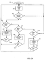
- FIG. 20 A flow chart exemplifying the mode selection of the gearshift 8 according to the invention is represented in Figure 20.
- the electronic control unit 40 When switched on, 101, the electronic control unit 40 enters a block 202 for managing the normal ride operating mode, in particular in manual operation.
- the system remains in this mode, in which it waits for and manages the signals coming from the gear-shifting request commands 43-46 in the way above described, negatively answering to the block 203 querying whether to change the operating mode.
- a mode selection request signal generated by one of the manual input commands, in particular by the pressing of the button 61, is monitored.
- the electronic control unit 40 queries in a block 204 whether one wishes to enter into a programming mode and, in the affirmative case, controls such a mode in a block 205 remaining there until it receives a negative answer to a block 206 requesting whether one wishes to continue, returning to the block 202 for controlling the normal ride operating mode.
- the electronic control unit 40 queries in a block 207 whether one wishes to enter into a diagnostics mode and, in the affirmative case, controls such a mode in a block 208 remaining there until it receives a negative answer to a block 209 requesting whether one wishes to continue, returning to block 202 for controlling the normal ride operating mode.
- the electronic control unit 40 queries in a block 210 whether one wishes to enter into the aforementioned operation mode selection and, in the affirmative case, controls such a mode in a block 211 remaining there until it receives a negative answer to a block 212 requesting whether one wishes to continue, returning to block 202 for controlling the normal ride operating mode, in particular in manual, semi-automatic or automatic operation as chosen by the rider.
- the values of the theoretical positions of the sprockets or of the differential amounts from which they derive, the values of the amounts of overstroke and/or the values of the gear-shifting positions can be corrected to take into account misalignments with respect to the chain 13 of the gearshift group 9, 10 overall and/or misalignments of the sprockets 11, 12 of the gearshift group 9, 10 with respect to each other, for example as illustrated in European patent applications no. 02425750 and no. 02425751 to the Applicant, both filed on 6 December 2002 and not yet published at the filing date of the present application. The descriptions of the aforementioned applications are here incorporated by reference.
- the microprocessor(s) electronic control unit 40 can, for example, be made in C-MOS technology, which has the advantage of having low consumption.
- the functionalities of the electronic control unit 40 described above can be accomplished by a software program loadable in a small computer.
Landscapes
- Engineering & Computer Science (AREA)
- Chemical & Material Sciences (AREA)
- Combustion & Propulsion (AREA)
- Transportation (AREA)
- Mechanical Engineering (AREA)
- Control Of Transmission Device (AREA)
- Gear-Shifting Mechanisms (AREA)
- Transmissions By Endless Flexible Members (AREA)
Abstract
Description
- The present invention concerns an electronically servo-assisted bicycle gearshift and a method for servo-assisting a bicycle gearshift, as well as a program and an electronic circuit having means for carrying out the method.
- An electronically servo-assisted bicycle gearshift generally comprises:
- a rear actuator and a front actuator, having a respective motor, for displacing a chain, through a guide element, in an axial direction with respect to a respective gearshift group comprising at least two sprockets or toothed wheels associated with the hub of the rear wheel (the sprockets also being called pinions and the chain guide element also being called rear derailleur or simply gearshift) of a bicycle and, respectively, with the axis of the pedal cranks (the sprockets or toothed wheels also being called crowns or gears and the guide element also being called front derailleur or simply derailleur), in a first direction (for example from a sprocket with a smaller diameter to a sprocket with a larger diameter, or "upwards gear-shifting") or in a second direction opposite to the first direction (for example, from a sprocket with a larger diameter to a sprocket with a smaller diameter or "downwards gear-shifting"),
- means for generating a signal requesting displacement of the chain from a first sprocket to a second adjacent sprocket of the respective gearshift group, such as levers associated with the two handlebar grips of the bicycle,
- an electronic control unit connected to the rear actuator and to the front actuator, operating, in a normal ride operating mode (i.e. wherein the gearshift is controlled manually by the rider or semiautomatically or automatically by the electronic control unit), for receiving the displacement request signal and driving the rear or front actuator, respectively, based upon the displacement request signal to displace the chain from a first sprocket to a second adjacent sprocket of the respective gearshift group, based upon logic positions ("logic values") representing the physical positions of the various sprockets, and
- a rear transducer and a front transducer for detecting the position of the actuators (and therefore of the chain guide elements) and for indicating it to the electronic control unit, so that the actuators are stopped when the desired position has been reached.
- Electronically servo-assisted bicycle gearshifts of the aforementioned type are described, for example, in patents US 5,480,356, US 5,470,277 and US 5,865,454 and in European
patent application EP 1 103 456, all of the Applicant; in patent US 6,047,230 of Spencer et al. and in German patent application DE 39 38 454 A1 of Ellsäßer. - In particular,
EP 1 103 456 describes a gearshift wherein the position transducers are of the absolute type, capable of providing an electrical signal indicating the absolute position of the derailleurs, so that after switching them on (again), such transducers take into account the actual position of the derailleurs, which could be slightly displaced due, for example, to vibrations caused by the travel of the bicycle. - It has been observed that, in normal ride operating mode, in order to assist a gear-shifting from a first sprocket to a second adjacent sprocket, sometimes it is not sufficient to displace the chain guide element (gearshift or derailleur) up to the second sprocket. In fact, due to the existing distance between the guide element and the second sprocket, on which the chain must engage, and due to the fact that the chain is at an angle during the gear-shifting, such a movement may not be sufficient to allow engagement of the chain on the second sprocket.
- To obtain a gear-shifting, in particular an upwards gear-shifting, the rear actuator or front actuator, respectively, must therefore be displaced in a position typically beyond the position corresponding to the second sprocket. The problem is particularly serious in the case of the front gearshift, where the chain is taut.
- Such a displacement in advanced position with respect to the second sprocket acts promoting the release of the chain from engagement with the first sprocket and the engagement of the chain on the second sprocket.
- In mechanical control gearshifts, the role of the actuator, of displacing the chain guide element, is carried out by a control mechanism comprising a steel cable slidably extending in a sheath ("Bowden cable") between a manual actuation lever and the chain guide element. The actuation of the lever in a first direction applies a traction on the chain guide element through the steel cable, whereas the actuation of the lever in a second opposite direction applies a thrust on the chain guide element through the steel cable, or lets the cable and the chain guide element free to be returned by a return spring.
- To ease gear-shifting, in some mechanical control gearshifts manufactured by the Applicant a control system has been implemented in which the actuation of the lever causes a movement of the steel cable of such a length that the chain guide element displaces for a greater length than that necessary to reach the position of the adjacent sprocket. When the control lever is released, the return spring acts to take the steel cable - and thus the chain guide element - back to the position corresponding to the second sprocket. In other words, the actuation of the control lever causes a temporary displacement of the chain guide element greater than the pitch between two adjacent sprockets of the gearshift group by a certain amount indicated hereafter as "overstroke".
- Such a mechanical control gearshift requires a periodical and relatively precise mechanical adjustment of the steel cable and of the tension of the return spring.
- Moreover, this mechanical solution has the drawback that it is possible to adjust the amount of the overstroke to a single value, which impacts as much in all of the upwards gear-shiftings as in all of the downwards gear-shiftings. Consequently, when the amount of the overstroke in a gearshift group is adjusted for an optimal gear-shifting in one direction (for example for upwards gear-shiftings), a gear-shifting in the opposite direction (in the example, downwards) is totally unsatisfactory. Alternatively it is necessary to adjust the amount of the overstroke to an intermediate value, obtaining sufficient but not optimal results in gear-shiftings in both directions.
- In the case of the front gearshift group it is particularly difficult to carry out an upwards gear-shifting towards the outermost sprocket, with the largest diameter. In this case even the provision of the overstroke may not be per se sufficient to ensure that the chain engages correctly. Particularly experienced riders could avoid this by keeping the front derailleur at the overstroke position for a certain amount of time. The time spent in overstroke position could however be only determined "by ear" and/or "by sight" by the rider, with the result that it could be too brief to give the desired result or so long as to cause harmful stresses to the mechanics of the gearshift or even the arrangement of the chain in positions such as to cause dangerous falls.
- The object of the invention is to provide an electronically servo-assisted gearshift that allows optimal gear-shifting in both directions, up and down, and between any pair of sprockets.
- In a first aspect thereof, the present invention concerns a method for electronically servo-assisting an electronically servo-assisted bicycle gearshift, comprising the steps of:
- a) receiving a signal requesting a displacement of a chain of a bicycle gearshift from a first sprocket to a second adjacent sprocket of a gearshift group comprising at least two sprockets,
- b1) if the first sprocket has a smaller diameter than the second sprocket, obtaining an upwards gear-shifting position for the second sprocket,
- b2) if the first sprocket has a larger diameter than the second sprocket, obtaining a downwards gear-shifting position for the second sprocket, and
- c) driving an actuator of the gearshift group to displace a guide element of the chain in an axial direction with respect to the gearshift group from the first sprocket to the upwards gear-shifting position for the second sprocket or to the downwards gear-shifting position for the second sprocket, respectively.
-
- Preferably the upwards gear-shifting position for the second sprocket and the downwards gear-shifting position for the second sprocket are asymmetrical with respect to a theoretical position of the second sprocket.
- The step b1) of obtaining an upwards gear-shifting position for the second sprocket may comprise the step of obtaining a theoretical position of the second sprocket.
- The step b1) of obtaining an upwards gear-shifting position for the second sprocket may also comprise the step of algebraically adding a predetermined amount of overstroke to the theoretical position of the second sprocket.
- Analogously, the step b2) of obtaining a downwards gear-shifting position for the second sprocket may comprise the step of obtaining a theoretical position of the second sprocket.
- The step b2) of obtaining a downwards gear-shifting position for the second sprocket may also comprise the step of algebraically adding a predetermined amount of overstroke to the theoretical position of the second sprocket.
- Advantageously the method may also comprise the sequential steps of:
- c1) temporarily maintaining the position of the chain guide element obtained in step c), and
- d) driving the actuator of the gearshift group to displace the chain guide element in the axial direction with respect to the gearshift group from the gear-shifting position to a theoretical position of the second sprocket.
-
- In an embodiment, the step c1) of temporarily maintaining the position comprises the step of waiting a predetermined time period.
- In an embodiment, the step c1) of temporarily maintaining the position comprises the step of waiting for an end-of-displacement-request signal.
- In an embodiment, the step c1) of temporarily maintaining the position comprises the sequential steps of waiting a predetermined minimum time period, and waiting for an end-of-displacement-request signal.
- In an embodiment, the step c1) of temporarily maintaining the position comprises the steps of monitoring the passing of a predetermined minimum time period, and monitoring the receiving of an end-of-displacement-request signal, wherein the execution of step d) takes place at the latest in time between the receiving of the end-of-displacement-request signal and the passing of the predetermined minimum time period.
- In an embodiment, the step c1) of temporarily maintaining the position comprises the steps of monitoring the receiving of an end-of-displacement-request signal, and monitoring the passing of a predetermined maximum time period, wherein the execution of step d) takes place at the first in time between the receiving of the end-of-displacement-request signal and the passing of the predetermined maximum time period.
- In an embodiment, the step c1) of temporarily maintaining the position comprises the steps of monitoring the passing of a predetermined minimum time period, monitoring the receiving of an end-of-displacement-request signal, and monitoring the passing of a predetermined maximum time period, wherein the execution of step d) takes place at the latest in time between the receiving of the end-of-displacement-request signal and the passing of the predetermined minimum time period if the receiving of the end-of-displacement-request signal precedes in time the passing of the predetermined maximum time period, or else upon the passing of the predetermined maximum time period if it precedes the receiving of the end-of-displacement-request signal.
- The method according to the invention advantageously comprises the step of setting a value of said or of each of said gear-shifting positions or of said or of each of said amounts of overstroke and/or of said or of each of said predetermined time periods.
- In a second aspect thereof, the invention concerns a program for electronically servo-assisting a bicycle gearshift, comprising program code means suitable for carrying out the steps of the above described method when the program is run on a computer.
- The program is preferably embodied in at least one microcontroller.
- Alternatively, the program can be stored in a computer memory or embodied in a read-only memory.
- In a third aspect thereof, the invention concerns an electronic circuit suitable for carrying out the steps of the above described method.
- In a fourth aspect thereof, the invention concerns a bicycle gearshift, comprising:
- a rear actuator and a front actuator, having a respective motor, to displace, through a guide element, a chain in an axial direction with respect to a respective gearshift group comprising at least two sprockets respectively associated with the hub of the rear wheel and with the axle of the pedal cranks of a bicycle,
- means for generating a signal requesting a displacement of the chain from a first sprocket to a second adjacent sprocket of the respective gearshift group,
- an electronic control unit connected to the rear actuator and to the front actuator, operating to receive the displacement request signal and to drive the rear or front actuator, respectively,
- the electronic control unit is suitable for driving the rear or front actuator, respectively, to displace a guide element of the chain from the first sprocket to an upwards gear-shifting position for the second sprocket if the first sprocket has a smaller diameter than the second sprocket, to a downwards gear-shifting position for the second sprocket if the first sprocket has a larger diameter than the second sprocket.
- The electronic control unit may comprise means for checking at least one condition selected from the group consisting of the passing of a predetermined time period and the receiving of an end-of-displacement-request signal and, subordinately to said checking means, be suitable for driving the rear or front actuator to displace the guide element of the chain from the upwards gear-shifting position for the second sprocket or, respectively, from the downwards gear-shifting position for the second sprocket to a theoretical position of the second sprocket.
- The electronic control unit may comprise memory means suitable for storing the upwards gear-shifting position and/or the downwards gear-shifting position for at least one second sprocket.
- Alternatively, the electronic control unit may comprise memory means suitable for storing at least one differential amount representing the difference between the theoretical position of at least one sprocket and the upwards gear-shifting position or, respectively, the downwards gear-shifting position for said at least one sprocket.
- In both cases the electronic control unit may also comprise memory means suitable for storing information representing the theoretical position of each sprocket.
- Typically the gearshift comprises a rear counter and a front counter indicating the position of the guide element of the chain with respect to the rear and front gearshift group, respectively.
- The gearshift according to the invention may comprise means for detecting the position of the rear actuator and front actuator, respectively, and providing it to the electronic control unit, comprising a rear transducer and a front transducer.
- In such a case, the electronic control unit may drive the rear or front actuator, respectively, in a feedback controlled manner by the position detected by the means for detecting the position.
- Preferably the motors of the rear and front actuators can be stepper motors and a displacement of the rear or front actuator by one step or by an integer multiple of steps corresponds to a unitary increase or decrease of the rear or front counter.
- Alternatively, the motors of the front and rear actuators can be selected from the group consisting of dc motors, brushless motors, asynchronous motors and hydraulic motors.
- The gearshift typically may comprise a power board arranged between the electronic control unit and the rear and front actuators.
- The electronic control unit may comprise at least one micro-controller made in C-MOS technology.
- Preferably, the electronic control unit is distributed and comprises many microcontrollers at a display unit and/or at a unit controlling manual input means and/or at a power board.
- The display unit is preferably removable.
- Further characteristics and advantages of the present invention shall become clearer from the following detailed description of some preferred embodiments thereof, made with reference to the attached drawings. In the drawings:
- figure 1 schematically illustrates a perspective view of a bicycle equipped with an electronically servo-assisted gearshift according to the present invention,
- figure 2 illustrates a block diagram of the electronically servo-assisted gearshift according to the present invention,
- Figure 3 illustrates a block diagram of the method for electronically servo-assisting an electronically servo-assisted gearshift according to the present invention,
- Figures 4-6 schematically illustrate different embodiments of front and rear memory means of the gearshift according to the present invention,
- Figures 7-12 schematically illustrate different embodiments of overstroke memory means of the gearshift according to the present invention,
- Figures 13-15 schematically illustrate different embodiments of gear-shifting memory means of the gearshift according to the present invention,
- Figures 16-19 schematically illustrate different embodiments of an optional step of the method according to the present invention, and
- figure 20 illustrates a flow chart exemplifying a mode selection of the gearshift according to the invention.
- With reference to figure 1, a
bicycle 1, in particular a racing bicycle, includes aframe 2 formed in a known way from tubular elements defining asupport structure 3 for arear wheel 4 and afork 5 for afront wheel 6. Ahandlebar 70 having a tubular structure is operatively connected to thefork 5. - The
frame 2, at its lower portion, supports an axle of the pedal cranks orpedal unit 7, of the conventional type, to actuate therear wheel 4 through an electronically servo-assisted gearshift according to the invention, generally indicated withreference 8. - The
gearshift 8 is substantially formed from arear gearshift group 9 and afront gearshift group 10. Therear gearshift group 9 includes a plurality of toothed wheels or sprockets or pinions 11 (ten in the illustrated example, but which can also be nine, eleven or whatever else in number) having different diameters and coaxial (axis A) with therear wheel 4. Thefront gearshift group 10 includes a plurality of toothed wheels or sprockets or crowns or gears 12 (three in the illustrated example, but which can also be two or whatever else in number), having different diameters and coaxial (axis B) with the axle of the pedal cranks 7. - The
sprockets 11 of therear gearshift group 9 and thesprockets 12 of thefront gearshift group 10 are selectively engageable by a loopedtransmission chain 13, to provide the different available gear ratios, through the electronically servo-assistedgearshift 8. - The different gear ratios can be obtained by moving a chain guide element or rear derailleur (or also simply gearshift) 14 of the
rear gearshift group 9 and/or a chain guide element or front derailleur (or also simply derailleur) 15 of thefront gearshift group 10. - The
rear derailleur 14 and thefront derailleur 15 are controlled by arespective actuator 16, 17 (Figure 2) typically comprising an articulated parallelogram mechanism and an electric motor with reducer to deform the articulated parallelogram. - A position sensor of the rear derailleur or
rear transducer 18 and a position sensor of the front derailleur or front transducer 19 (Figure 2) are associated with theactuators 16, 17. - The details of the construction of the
derailleurs respective actuators 16, 17 and of the respective position sensors ortransducers - In particular, the
transducers EP 1 103 456 A2, suitable for providing an electrical signal indicating the absolute position of thederailleurs - An
electronic power board 30, equipped with a battery, provides the electrical power to the motors of theactuators 16, 17, to thetransducers electronic control unit 40 and preferably to adisplay unit 60. The battery is preferably of the rechargeable type and therear derailleur 14 can include, in a per se known way, a dynamo-electric unit for recharging the battery. - In the present description and in the attached claims, under electronic control unit 40 a logic unit shall be meant, which can however be formed of many physical units, in particular of one or more distributed microprocessors which can be held in the
display unit 60 and/or in theelectronic power board 30 and/or in a command unit. - In such a logic meaning, the
electronic control unit 40 comprises, besides the microprocessor(s), memory means which can comprise one or more device(s) for storing the instructions which encode the management program of the electronic gearshift, for the temporary storing of service variables to carry out the program itself (registers) as well as for volatile, non-volatile or permanent storing of some values specified later in the description. Regarding these values, in the present description and in the attached claims, the memory means are distinct in rear memory means, front memory means, overstroke memory means and gear-shifting memory means. It must however be clear that such a distinction is simply to be taken from the functional point of view and does not necessarily have to correspond to a physical distinction of the storing devices. In other words, one or more physical devices can be used for each of the memory means indicated above or, vice-versa, each of the memory means indicated above can physically be embodied by a respective physical device or by memory locations of one or more physical devices. - The storing devices can be of one or more types among read only, write once, or read/write, random access or sequential access memories, and they can be made in various technologies, such as optical memories, magnetic memories, etc.
- The storing device(s) can be contained in the
display unit 60 and/or in theelectronic power board 30 and/or in the command unit and/or they can be distinct devices. - In a particularly preferred embodiment, the
display unit 60 can be removed from thebicycle 1 and houses at least part of the memory means of theelectronic control unit 40. In such a case the values set by the user for various parameters of the electronically servo-assistedgearshift 8 are preferably stored in the memory means housed in thedisplay unit 60. This embodiment is advantageous above all in the case of racing bicycles, where the values set by the user reflect the know-how of the rider and are therefore confidential, and also since it allows the display unit, which is relatively expensive, to be safeguarded. - The
electronic power board 30 is, for example, housed in one of the tubes of thehandlebar 70, in one of the tubes of theframe 2, for example at a support for a drinking bottle (not illustrated), or in thedisplay unit 60, which is preferably housed centrally on thehandlebar 70. - The information transfer between the various components is carried out through electrical cables, advantageously housed inside the tubes of the
frame 2, or else in a wireless mode, for example with the Bluetooth protocol. - During travel, the rear and
front derailleurs actuators 16, 17, by theelectronic control unit 40 based upon signals requesting a displacement of the chain towards a sprocket adjacent to the one upon which the chain is engaged (upwards and downwards gear-shifting request signals) established by manual command devices, or semi-automatically or automatically by theelectronic control unit 40 itself. The manual command devices can, for example, compriselevers brake lever 41 on a grip of thehandlebar 70 for the upwards and downwards gear-shifting signals, respectively, of therear gearshift group 9, and levers 45, 46 (Figure 2) associated with the brake lever on the other grip of thehandlebar 70 for the upwards or downwards gear-shifting signals of the front gearshift group 10 (thelevers - As an alternative to the
levers 43, 44 (45, 46) two manually operated buttons, or two buttons which can be operated by a swing lever can be provided. - The
electronic control unit 40 is also associated with the twotransducers actuators 16, 17 when therespective derailleur adjacent sprocket 11 or 12 (with a larger or smaller diameter, respectively) to the one with which it was engaged when the displacement request signal (upwards or downwards gear-shifting request signal, respectively) was generated through themanual command device electronic control unit 40. Such a position is indicated in the present description and in the attached claims as "gear-shifting position". According to the present invention, as shall be better explained hereafter, the gear-shifting position for at least one givensprocket gearshift group - In an alternative embodiment, the motors of the
actuators 16, 17 are stepper motors which are driven by an appropriate number of steps for each upwards or downwards gear-shifting and then automatically stopped, whereas thetransducers electronic control unit 40 so that it can possibly provide to actuate once again the motors of theactuators 16, 17 in case the gear-shifting position has not been reached. This can, for example, be due to the fact that the resisting torque offered by thederailleur - More specifically, according to the present invention, the
electronic control unit 40 comprises arear counter 47 and afront counter 48. Thecounters - The
electronic control unit 40, in the normal ride operating mode of thegearshift 8, drives theactuators 16, 17 and tracks their position increasing or decreasing thecounters transducers - According to some embodiments of the electronically servo-assisted
gearshift 8 of the invention, the memory means of theelectronic control unit 40 comprise (figures 4-6, described hereafter) rear memory means 49 for the theoretical positions of thesprockets 11 of therear gearshift group 9 and front memory means 50 for the theoretical positions of thesprockets 12 of thefront gearshift group 10. - Under theoretical positions of the
sprockets counters derailleurs sprockets - In such embodiments of the electronically servo-assisted
gearshift 8 according to the present invention, the memory means of theelectronic control unit 40 also comprise overstroke memory means 51 (figures 7-12, described hereafter) for at least a differential amount, indicated as "amount of overstroke". The or each amount of overstroke represents the offset between the theoretical position of thesprocket 11 and/or 12, indicated by the memory means 49 and/or 50, and the position that theguide element chain 13 must take up during an upwards and/or downwards gear-shifting to assist the gear-shifting itself, i.e. the upwards and/or downwards gear-shifting position defined above. - With reference to the block diagram of figure 3, which represents a method according to the invention for electronically servo-assisting the
gearshift 8 and which generally applies both to therear gearshift group 9 and to thefront gearshift group 10, if thechain 13 is, block 100, at a first sprocket 11 (12) and the counter 47 (48) has a first logic value, when the rider actuates the manual upwards gear-shifting request command 43 (45), block 101, or respectively, the manual downwards gear-shifting request control 44 (46), block 102 (or when such a request is generated by theelectronic control unit 40 itself), theelectronic control unit 40 firstly provides for obtaining the gear-shifting position for the second sprocket 11 (12), block 103 or 104 respectively, which according to the present invention shall be an upwards gear-shifting position, if the first sprocket has a smaller diameter than the second sprocket (block 103), and a downwards gear-shifting position, if the first sprocket has a larger diameter than the second sprocket (block 104). As mentioned, the downwards gear-shifting position is preferably different from the upwards gear-shifting position at least for one second sprocket, and more preferably such positions are asymmetrical around the theoretical position of the second sprocket. - Once the upwards gear-shifting position (block 103) or the downwards gear-shifting position (block 104), respectively, has been obtained, the
electronic control unit 40 takes care of driving, block 109 or 110, respectively, the actuator 16 (17) to displace the chain along the axis A (B) in a first direction which goes from the first sprocket to the second sprocket until the counter 47 (48) reaches the value indicated by the upwards gear-shifting position or by the downwards gear-shifting position, respectively. - In case the
actuators 16, 17 comprise stepper motors, advantageously a movement of one step or an integer multiple of steps of the stepper motor, in a first or second direction of rotation, corresponds to each unitary increase or decrease of thecounter - After the aforementioned driving step, the
electronic control unit 40 can optionally take care of carrying out a stay and repositioning step, schematically indicated by the dashedblocks - In these embodiments, the step of obtaining the upwards gear-shifting position (block 103), or respectively the downwards gear-shifting position (block 104), is carried out through the steps of:
- obtaining, block 105 or 106, respectively, the theoretical position of the second sprocket 11 (12) from the rear 49 (front 50) memory means, reading it directly from the memory means 49 (50) or deriving it from the information read from the memory means 49 (50), as better specified hereafter;
- where provided for, as better specified hereafter, algebraically adding (block 107 and/or 108) the suitable amount of overstroke, stored in the overstroke memory means 51, to the theoretical position of the second sprocket 11 (12).
- In a first embodiment (Figure 4), the rear and front memory means 49 and 50 are suitable for directly storing a value associated with each
sprocket respective gearshift group sprocket rear gearshift group 9 comprising ten sprockets or pinions 11, the rear memory means 49 are suitable for storing a logic value R1 associated with the wheel with the smallest diameter, a logic value R2 associated with the sprocket immediately adjacent to it, with a slightly larger diameter, a logic value R3 associated with the sprocket immediately adjacent to it, with a yet larger diameter etc., up to a logic value R10 associated with the sprocket with the largest diameter; in the exemplifying case offront gearshift group 10 comprising three sprockets or crowns 12, the front memory means 50 are suitable for storing a logic value F1 associated with the wheel with the smallest diameter, a logic value F2 associated with the sprocket with an intermediate diameter and a logic value F3 associated with the sprocket with the largest diameter. - In such an embodiment, the
electronic control unit 40 obtains, inblock second sprocket memory - In a second embodiment (Figure 5), the rear memory means 49 are suitable for storing a differential amount associated with each pair of
adjacent sprockets 11. Thus, in the exemplifying case ofrear gearshift group 9 comprising ten sprockets or pinions 11, the rear memory means 49 are suitable for storing a differential amount ΔR1-2 associated with the pair consisting of thesprocket 11 with the smallest diameter and thesprocket 11 immediately adjacent to it (with a slightly larger diameter), a differential amount ΔR2-3 associated with the pair consisting of this latter sprocket and that one adjacent to it, etc., up to a differential amount ΔR9-10 associated with the pair ofsprockets 11 having the largest diameters; in the exemplifying case offront gearshift group 10 comprising three sprockets or crowns 12, the front memory means 50 are suitable for storing two differential amount ΔF1-2 and ΔF2-3. If the theoretical position of the sprocket with the smallest diameter does not correspond to the zero value of thecounter - In such an embodiment, the
electronic control unit 40 obtains, in block 105 (or inblock 106 respectively), the theoretical position of thesecond sprocket first sprocket second sprocket chain 13 is at the first sprocket, block 100. - As an alternative to the use of the current value of the counter at
block 100, in particular when the stay and repositioning step 111 (112) is absent, theelectronic control unit 40 obtains, in block 105 (or inblock 106, respectively), the theoretical position of thesecond sprocket - In a third embodiment, which can be implemented when the
gearshift groups sprockets adjacent sprockets 11 of therear gearshift group 9 is equal to the pitch betweenadjacent sprockets 12 of thefront gearshift group 10, there can be only a single memory means, for example just thefront memory 49. If the theoretical position of the sprocket with the smallest diameter does not correspond to the zero value of thecounter - In such an embodiment, the
electronic control unit 40 obtains, in block 105 (or inblock 106, respectively), the theoretical position of thesecond sprocket chain 13 is at the first sprocket, block 100. - Alternatively, the
electronic control unit 40 obtains the theoretical position of thesecond sprocket - Irrespectively of the embodiment of the front and rear memory means 49, 50, various embodiments of the overstroke memory means 51 are possible.
- According to a first embodiment of the present invention (figure 7) just one amount of overstroke E is provided for, generally represented by a relative number.
- The
electronic control unit 40 can use the single amount of overstroke E in various ways according to the block diagram of figure 3. In a first particularly preferred way, such an amount of overstroke E is algebraically added in the case of an upwards gear-shifting, block 107, to the theoretical position of the second sprocket obtained inblock 105 in the ways defined above, whereasblock 108 is absent; in such a case the amount of overstroke E is typically represented by a positive number. - In a second way, such an amount of overstroke E is algebraically added in the case of a downwards gear-shifting, block 108, to the theoretical position of the second sprocket obtained in
block 106, whereasblock 107 is absent; in such a case the amount of overstroke E is typically represented by a negative number so that its absolute value is subtracted from the theoretical position of the second sprocket. - In a third way, such an amount of overstroke E is algebraically added in the case of an upwards gear-shifting, block 107, to the theoretical position of the second sprocket obtained in
block 106, whereas in the case of a downwards gear-shifting, block 108, its opposite (where -X indicates the opposite to X) is algebraically added to the theoretical position of the second sprocket obtained inblock 106. In such a case the amount of overstroke E is typically represented by a positive number. - It should be noted that the amount of overstroke E, as well as the theoretical position of the
second sprocket block electronic control unit 40; typically, in the second and third ways the theoretical position of the second sprocket can be corrected with respect to the physical position of the sprocket itself. - Since the
chain 13 is taut at theguide element 15 of thefront gearshift group 10, but not taut at theguide element 14 of therear gearshift group 9, to make the electronically servo-assistedgearshift 8 and the method for servo-assisting it according to the present invention particularly simple, it can be sufficient to provide for thealgebraic adding steps algebraic adding step 107 in the case of an upwards gear-shifting, only for thefront gearshift group 10 or even only in the case of the gear-shifting towards thesprocket 12 with the largest diameter of thefront gearshift group 10. - According to a second embodiment (figure 8), the overstroke memory means 51 are suitable for storing an amount E+ of overstroke for an upwards gear-shifting and an amount E- of overstroke for a downwards gear-shifting, in general represented by relative numbers. More typically, the amount E+ of overstroke for an upwards gear-shifting is represented by a positive number and the amount of overstroke E- for a downwards gear-shifting is represented by a negative number.
- In the case of an upwards gear-shifting, the
electronic control unit 40, inblock 107 of figure 3, algebraically adds the amount of overstroke E+ for an upwards gear-shifting to the theoretical position of thesecond sprocket block 105; in the case of a downwards gear-shifting, theelectronic control unit 40, inblock 108, algebraically adds the amount of overstroke E- for a downwards gear-shifting to the theoretical position of thesecond sprocket block 106. - Also in the case of the second embodiment, to simplify the electronically servo-assisted
gearshift 8 and the method for servo-assisting it of the present invention, it may be sufficient to provide for thealgebraic adding steps front gearshift group 10. - On the contrary, since as stated the tension of the
chain 13 is different at theguide elements front gearshift groups adjacent sprockets rear gearshift group 9 can be different from the pitch betweenadjacent sprockets 12 of thefront gearshift group 10, and since the distance between theguide element chain 13 and thesprockets front 9 and rear 10, it may be suitable to differentiate the values of overstroke to be applied to therear gearshift group 9 and to thefront gearshift group 10. - Thus, in a third embodiment (figure 9), the overstroke memory means 51 are suitable for storing a single amount of overstroke ER for the
rear gearshift group 9 and a single amount of overstroke EF for thefront gearshift group 10, each independently used by theelectronic control unit 40 in one of the three ways outlined above with reference to the embodiment of figure 7 and to which the other considerations outlined with reference to such a figure 7 apply. - In a fourth embodiment (figure 10), the overstroke means 51 are suitable for storing, for the
rear gearshift group 9, an amount ER+ of overstroke for an upwards gear-shifting and an amount ER- of overstroke for a downwards gear-shifting and, for thefront gearshift group 10, an amount EF+ of overstroke for an upwards gear-shifting and an amount EF- of overstroke for a downwards gear-shifting, to be used in the way described above with reference to the embodiment of figure 8. - The amounts of overstroke according to the fourth embodiment ER+, ER-, EF+, EF- are also generally represented by relative numbers, but typically the amounts ER+, EF+ are represented by positive numbers so that their absolute value is added to the theoretical position of the
second sprocket second sprocket chain guide element - According to a fifth embodiment, which favours for optimisation of the operation of the electronically servo-assisted
gearshift 8 and of the method for servo-assisting it of the present invention with respect to the single gear-shiftings, the overstroke memory means (figure 11) are suitable for storing an amount ERj of overstroke for each sprocket of therear gearshift group 9 and an amount EFj of overstroke for each sprocket of thefront gearshift group 10. The amounts of overstroke ERj, EFj can be managed by theelectronic control unit 40 inblock 107 and/or inblock 108 in the three ways described above with reference to the embodiment of figure 7. If the first way is used, in which in the case of an upwards gear-shifting the amount of overstroke ERj or EFj associated with the second sprocket is algebraically added, in particular added in an absolute value, to the theoretical position of the second sprocket, whereasblock 108 is absent, no amount of overstroke associated with the sprocket with the smallest diameter shall be provided for; if the second way is used, in which in the case of a downwards gear-shifting the amount of overstroke ERj or EFj associated with the second sprocket is algebraically added, in particular subtracted in an absolute value, to the theoretical position of the second sprocket, whereasblock 107 is absent, no amount of overstroke associated with the sprocket with the largest diameter shall be provided for. - According to a sixth embodiment, the overstroke memory means (figure 12) are suitable for storing an amount of overstroke for an upwards gear-shifting ER+j, EF+j and an amount of overstroke for a downwards gear-shifting ER-j, EF-j for each
intermediate sprocket gearshift group rear gearshift group 9 having tensprockets 11, eighteen amounts shall be provided for and in the case offront gearshift group 10 comprising threesprockets 12, four amounts shall be provided for. - The
electronic control unit 40, inblock 107 of figure 3, algebraically adds the amount of overstroke ER+j, EF+j for an upwards gear-shifting associated with the second sprocket to the theoretical position of thesecond sprocket electronic control unit 40, inblock 108, algebraically adds the amount of overstroke ER-j, EF-j for a downwards gear-shifting associated with the second sprocket to the theoretical position of thesecond sprocket - It is worth highlighting that in all of the embodiments of the overstroke memory means 51 described above it is possible to choose between the implementation of an adding operation in
blocks block 107 and subtraction operations inblock 108 associated with the storing of typically positive, but also relative, numbers in the overstroke memory means 51. The upwards gear-shifting position obtained inblock 103 is generally different from the downwards gear-shifting position obtained inblock 104, because it is obtained through a different application of a same absolute overstroke value in the aforementioned two blocks, because it is obtained through the application of the or an overstroke value in just one of the aforementioned blocks, or because it is obtained through an analogous application of different overstroke values in the aforementioned two blocks. Even more preferably, the upwards and downwards gear-shifting positions are asymmetrical about the theoretical position of the second sprocket, like in the latter two cases. - According to other embodiments of the electronically servo-assisted
gearshift 8 according to the present invention, theelectronic control unit 40 comprises gear-shifting memory means 52 instead of the overstroke memory means 51. - In a first embodiment (figure 13), the gear-shifting memory means 52 also replace the front memory means 49 and the rear memory means 50 and are suitable for directly storing an upwards gear-shifting position R+j, F+j and a downwards gear-shifting position R-j, F-j for each
intermediate sprocket gearshift group - In other words, the gear-shifting memory means 52 are suitable for storing the upwards gear-shifting position towards each
sprocket sprocket - Therefore, two (different) gear-shifting positions correspond to each
non-end sprocket front gearshift group sprocket end sprocket - In the case illustrated in figure 13, shown merely as an example, of a
rear gearshift group 9 comprising tensprockets 11 and of afront gearshift group 10 comprising threesprockets 12, the gear-shifting memory means 52 are suitable for storing the nine upwards gear-shifting positions R+2, R+3, ..., R+j, ..., R+10 and the nine downwards gear-shifting positions R-1, R-2, ..., R-i, ..., R-9, as well as the two upwards gear-shifting positions F+2, F+3 and the two downwards gear-shifting positions F-1, F-2. - In the method according to the present invention for servo-assisting a
gearshift 8 according to this embodiment, inblocks electronic control unit 40 obtains the gear-shifting positions, namely the values that thecounters derailleurs chain 13 with thesprockets - Analogously to what has been indicated with reference to the embodiments providing for the overstroke memory means 51, the upwards gear-shifting positions, or preferably the downwards gear-shifting positions, could coincide with the theoretical positions of the
second sprockets chain 13 to obtain the gear-shifting. - In accordance therewith, in still alternative embodiments of the
gearshift 8 according to the present invention, theelectronic control unit 40 comprises the rear and front memory means 49, 50 in one of the various embodiments described above (figures 4-6) and, in the gear-shifting memory means 52, just the upwards gear-shifting position (figure 14) or just the downwards gear-shifting position (figure 15), respectively, for each sprocket apart from the sprocket with the smallest or largest diameter, respectively. - It can easily be understood that with such embodiments, in the method according to the invention the step of obtaining the upwards gear-shifting position (block 103) or the step of obtaining the downwards gear-shifting position (block 104), respectively, shall be carried out by reading the value directly from the gear-shifting memory means 52, whereas the step of obtaining the downwards gear-shifting position (block 104) or the step of obtaining the upwards gear-shifting position (block 103), respectively, shall be carried out through the step, block 106 or block 105 respectively, of obtaining the theoretical position of the second sprocket from the front and rear memory means 49, 50.
- Moreover, analogously to what has been indicated with reference to the embodiments providing for the overstroke memory means 51, in embodiments providing for the gear-shifting memory means 52 in combination with the front and rear memory means 49, 50, the upwards and downwards gear-shifting positions, respectively, can be provided for not all of the sprockets, but only for the sprockets in which a gear-shifting position which is different from the theoretical position is necessary. In particular, in the gear-shifting memory means 52 according to the embodiment of figure 14, just the upwards gear-shifting position for the
sprocket 12 with the largest diameter of thefront gearshift group 10 could be provided for. - The embodiments of figures 13-15 have the advantage of requiring little memory and of not requiring algebraic adding operations by the
electronic control unit 40. However, to implement the optional step of stay and repositioning illustrated byblocks - Embodiments in which the gear-shifting positions are stored as differential amounts, analogously to the embodiments of figures 5 and 6, are also possible.
- It can easily be understood that, for a specific electronically servo-assisted
gearshift 8, the values of the gear-shifting positions stored in the gear-shifting memory means 52 differ from the values of the theoretical positions by an offset that would correspond to the or the respective amount of overstroke in one of the embodiments providing for the overstroke memory means 51. In other words, the values of the gear-shifting positions stored in the gear-shifting memory means 52 in se encompass the amount or amounts of overstroke. - It should also be understood that it can be envisaged to use embodiments of the memory means, and/or ways of using the amounts of overstroke stored in the overstroke memory means 51, which are different for the
rear gearshift group 9 and for thefront gearshift group 10. - As mentioned, the method according to the present invention for servo-assisting a bicycle gearshift can provide, after the
guide element chain 13 has been taken into the gear-shifting position atblocks block 111 and/or byblock 112 of figure 3. - According to the present invention, in the optional step of stay and
repositioning electronic control unit 40, once a certain period of time has elapsed and/or once an end-of-gear-shifting-request signal has been received, as better explained hereafter, drives (in a step indicated byblock 116 in figures 16-19) theactuator 16, 17 to displace thechain 13 until thecounter second sprocket blocks - It should be understood that the displacement shall take place along the axis A, B in the first direction from the first sprocket to the second sprocket or more typically in the second direction from the second sprocket to the first sprocket according to the amount of overstroke or, in the case of the embodiments of figures 13-15, according to whether the upwards gear-shifting position is smaller or greater than the theoretical position of the second sprocket, or the downwards gear-shifting position is greater or smaller than the theoretical position of the second sprocket.
- The advisability of providing for such a step of stay and
repositioning chain 13 to correctly engage with thesecond sprocket - As mentioned in the introductory part of the present description, the problem is particularly serious in the case of upwards gear-shifting towards the
sprocket 12 with the largest diameter of the front gearshift group 10 (the outermost one). With the Applicant's mechanical control gearshifts equipped with overstroke described in the introductory part, particularly skilled riders could avoid this by maintaining pressure on the control lever and thus thederailleur - In a first embodiment of the step of stay and
repositioning actuator 16, 17 to displace theguide element chain 13 in the theoretical position of thesecond sprocket 11, 12 (block 116) is subordinated to the passing of a predetermined period of time after thestep actuator 16, 17 to displace theguide element chain 13 in the gear-shifting position. - More specifically, the
electronic control unit 40 takes care, inblock 113, of activating a timer and, inblock 114, of monitoring the passing of a predetermined time period T. The timer can, of course, be a count-down or a count-up one and can be implemented by a memory variable managed by the clock signal of a microprocessor of theelectronic control unit 40 or by a dedicated device. - When the predetermined time period T has passed, if necessary in a block 115 a step of obtaining the theoretical position of the
second sprocket block 116, the aforementioned step of driving theactuator 16, 17 to displace thechain 13 until thecounter second sprocket step 115 of obtaining the theoretical position of thesecond sprocket block - In a second embodiment of the step of stay and
repositioning actuator 16, 17 to displace theguide element chain 13 in the theoretical position of thesecond sprocket 11, 12 (block 116) is subordinated to the receiving of an end-of-displacement-request signal after thestep actuator 16, 17 to displace theguide element chain 13 in the gear-shifting position. - More specifically, the
electronic control unit 40 takes care, inblock 117, of monitoring the receiving of an end-of-displacement-request signal. In the normal ride operating mode, with automatic or semi-automatic operation, it is theelectronic control unit 40 itself that generates said end-of-displacement-request signal. Typically, in the normal ride operating mode with manual control, such a signal is, on the other hand, generated by the release of the gear-shifting request control 43-46 by the rider. - When such a signal has been received, if necessary, in a
block 115, the step of obtaining the theoretical position of thesecond sprocket block 116, the aforementioned step of driving theactuator 16, 17 to displace thechain 13 until thecounter second sprocket - In a third embodiment of the step of stay and
repositioning actuator 16, 17 to displace theguide element chain 13 in the theoretical position of thesecond sprocket 11, 12 (block 116) is subordinated to the receiving of an end-of-displacement-request signal, in turn subordinated to the passing of a predetermined minimum period of time after thestep actuator 16, 17 to displace theguide element chain 13 in the gear-shifting position. - More specifically, the
electronic control unit 40 takes care, in ablock 118, of activating a timer and, in ablock 119, of monitoring the passing of a predetermined minimum time period Tmin. As for the timer, the considerations outlined above with reference to the embodiment of figure 16 are valid. - When the predetermined minimum time period Tmin has passed, the end-of-displacement-request signal (block 117) is waited for. In manual operation, it may happen that the release of the control 43-46 by the rider already takes place during the passing of the predetermined minimum time period Tmin (i.e. during the cyclic execution of block 119) and in such a case the
electronic control unit 40 will take care of inhibiting or holding up the end-of-displacement-request signal until the predetermined minimum time period Tmin has passed. - Once the two-fold condition that the predetermined minimum time period Tmin has passed and that the end-of-displacement-request signal has been received by the
electronic control unit 40 has been met, if necessary (i.e. ifstep second sprocket block 116, the aforementioned step of driving theactuator 16, 17 to displace thechain 13 until thecounter second sprocket - In a fourth embodiment of the step of stay and
repositioning actuator 16, 17 to displace theguide element chain 13 in the theoretical position of thesecond sprocket 11, 12 (block 116) takes place once an end-of-displacement-request signal has been received, but subordinated to the passing of a predetermined minimum period of time and to the passing of a predetermined maximum period of time. In other words, drivingstep 116 is carried out at the latest in time of the receiving of end-of-displacement-request signal and the passing of the predetermined minimum time period if the end-of-displacement-request signal is received before the predetermined maximum time period has passed, or else when the predetermined maximum time period has passed if the end-of-displacement-request signal has not yet been received. In such a case, theelectronic control unit 40 shall ignore the end-of-displacement-request signal received thereafter. - More specifically, the
electronic control unit 40 first of all takes care, inblock 120, of activating one count-up timer or two count-down timers, one set at a predetermined minimum time period Tmin and the other set at a predetermined maximum time period Tmax. - The
electronic control unit 40 then takes care of monitoring (block 117) the receiving of the end-of-displacement-request signal. While the end-of-displacement-request signal has not been received (output NO of block 117), theelectronic control unit 40 monitors, in ablock 121, the passing of the predetermined maximum time period Tmax. - While the predetermined maximum time period Tmax has not passed (output NO in block 121), the electronic control unit continues to monitor the receiving of the end-of-displacement-request signal (return to block 117).
- When the predetermined maximum time period Tmax has passed without the end-of-displacement-request signal having been received (output NO of
block 117 and output YES of block 121), if necessary (i.e. ifstep second sprocket block 116, the aforementioned step of driving theactuator 16, 17 to displace thechain 13 until thecounter second sprocket - If, on the other hand, the end-of-displacement-request signal is received (output YES of block 117) before it has been checked, in the previous cycle, that the predetermined maximum time period Tmax has passed, the
electronic control unit 40 checks the passing of the predetermined minimum time period Tmin (block 119). - If the predetermined minimum time period Tmin has not yet passed (output NO of block 119), the
electronic control unit 40 continues to monitor the passing of such a predetermined minimum time period Tmin remaining atblock 119. If, on the other hand, when the end-of-displacement-request signal is received the predetermined minimum time period Tmin has passed, or as soon as such a period has passed (output YES of block 119), if necessary the step (block 115) of obtaining the theoretical position of thesecond sprocket block 116, the step of driving theactuator 16, 17 to displace thechain 13 until thecounter second sprocket - The provision of a predetermined maximum time period Tmax, after the passing of which the driving
step 116 is carried out independently of the receiving of the end-of-displacement-request signal, is advantageous since, as mentioned, an excessive amount of time in the gear-shifting position could damage the mechanics of thegearshift 8 and turn out to be dangerous for the rider. - In a fifth embodiment the step of stay and
repositioning block 119 of figure 19 is absent and when the end-of-displacement-request signal has been received, it passes directly to the step of obtaining the theoretical position of the second sprocket, if necessary (block 115), and to the step of driving the actuator (block 116), as indicated by the dashed arrow in figure 19. - In a sixth embodiment the step of stay and
repositioning block 121 of figure 19 is absent and until the end-of-displacement-request signal has been received, it remains inblock 117, as indicated by the phantom arrow in figure 19. - The step of activating the timer(s) 113, 118, 120 can, in alternative embodiments which are not shown, be carried out before the
step actuator 16, 17 to displace theguide element chain 13 in the gear-shifting position. - It is worth highlighting that the step of stay and
repositioning second sprocket second sprocket bicycle 1 in case thechain - It should be understood that the sequentiality of the execution of
blocks - In the various aforementioned embodiments, the values of the theoretical positions of the sprockets or of the differential amounts from which they derive, the values of the amounts of overstroke and/or the values of the gear-shifting positions, as well as the values of the time periods of the optional step of stay and repositioning, are preset in the factory to default values.
- Preferably, the values listed above, or at least some of them, can however be modified by the user; in such a case it is suitable to provide for the possibility of returning to the default values (corresponding to nominal or average values), suitably stored in read-only memory means.
- More specifically, according to the invention, the electronically servo-assisted
gearshift 8, and in particular itselectronic control unit 40, is suitable to operate, besides in the normal ride operating mode, in other operating modes, including a programming mode of the microprocessor(s) of theelectronic control unit 40, a diagnostics mode, a "choice-of-operation mode" in which it is possible to choose between manual, automatic or semi-automatic control of the gearshift, for example as described in document US 5,865,454, and a setting mode. - The various operating modes are selected through manual mode selection command means, forming a user interface with the
electronic control unit 40, preferably in cooperation with thedisplay unit 60. The manual mode selection command means preferably comprise twobuttons display unit 60. The user interface can of course comprise other buttons or levers, such as thebutton 63, at thedisplay unit 60 and/or at the grips of thehandlebar 70, used in the other operating modes. - For example, when the rider presses the
button 61 arranged centrally under thedisplay unit 60, theelectronic control unit 40 can show on thedisplay unit 60 the various operating modes in cyclical sequence and the mode selection means can comprise thesame button 61 for accepting the operating mode currently displayed on thedisplay unit 60 and a button, for example thebutton 62 to the right of thedisplay unit 60, to not accept it and cause the display of the next operating mode. - Alternatively, the
electronic control unit 40 can show on the display unit 60 a menu containing all the various operating modes, and the mode selection means can comprise a button for scrolling a selection cursor cyclically in the menu, or two buttons to scroll the selection cursor in the menu in the two directions, as well as a button for accepting the operating mode upon which the selection cursor is currently displayed. - The buttons for accepting and not accepting the operating mode, or the buttons for scrolling the cursor, can also be embodied by the same upwards and downwards gear-shifting request commands 43, 44 or 45, 46, the
electronic control unit 40 suitably interpreting the signal generated by the pressing of the buttons according to the context, for example through logic gates or Boolean functions. - A flow chart exemplifying the mode selection of the
gearshift 8 according to the invention is represented in Figure 20. - When switched on, 101, the
electronic control unit 40 enters ablock 202 for managing the normal ride operating mode, in particular in manual operation. The system remains in this mode, in which it waits for and manages the signals coming from the gear-shifting request commands 43-46 in the way above described, negatively answering to theblock 203 querying whether to change the operating mode. In the query block 203 a mode selection request signal, generated by one of the manual input commands, in particular by the pressing of thebutton 61, is monitored. - In case the mode selection request signal is activated, output Yes from the
query block 203, theelectronic control unit 40 queries in ablock 204 whether one wishes to enter into a programming mode and, in the affirmative case, controls such a mode in ablock 205 remaining there until it receives a negative answer to ablock 206 requesting whether one wishes to continue, returning to theblock 202 for controlling the normal ride operating mode. In the case of a negative answer to block 204, theelectronic control unit 40 queries in ablock 207 whether one wishes to enter into a diagnostics mode and, in the affirmative case, controls such a mode in ablock 208 remaining there until it receives a negative answer to ablock 209 requesting whether one wishes to continue, returning to block 202 for controlling the normal ride operating mode. In the case of a negative answer to block 207, theelectronic control unit 40 queries in ablock 210 whether one wishes to enter into the aforementioned operation mode selection and, in the affirmative case, controls such a mode in ablock 211 remaining there until it receives a negative answer to ablock 212 requesting whether one wishes to continue, returning to block 202 for controlling the normal ride operating mode, in particular in manual, semi-automatic or automatic operation as chosen by the rider. - The values of the theoretical positions of the sprockets or of the differential amounts from which they derive, the values of the amounts of overstroke and/or the values of the gear-shifting positions can be corrected to take into account misalignments with respect to the
chain 13 of thegearshift group sprockets gearshift group - The microprocessor(s)
electronic control unit 40 can, for example, be made in C-MOS technology, which has the advantage of having low consumption. - As an alternative to implementation through dedicated hardware, the functionalities of the
electronic control unit 40 described above can be accomplished by a software program loadable in a small computer.
Claims (30)
- Method for electronically servo-assisting an electronically servo-assisted bicycle gearshift (8), comprising the steps of:a) receiving (101, 102) a signal requesting a displacement of a chain (13) of a bicycle gearshift (8) from a first sprocket (11, 12) to a second adjacent sprocket (11, 12) of a gearshift group (9, 10) comprising at least two sprockets,b1) if (101) the first sprocket has a smaller diameter than the second sprocket, obtaining (103) an upwards gear-shifting position for the second sprocket,b2) if (102) the first sprocket has a larger diameter than the second sprocket, obtaining (104) a downwards gear-shifting position for the second sprocket, andc) driving (109, 110) an actuator (16, 17) of the gearshift group (9, 10) to displace a guide element (14, 15) of the chain (13) in an axial direction with respect to the gearshift group (9, 10) from the first sprocket to the upwards gear-shifting position for the second sprocket or to the downwards gear-shifting position for the second sprocket, respectively.
- Method according to claim 1, characterised in that the upwards gear-shifting position for the second sprocket (11, 12) and the downwards gear-shifting position for the second sprocket (11, 12) are asymmetrical with respect to a theoretical position of the second sprocket (11, 12).
- Method according to claim 1 or 2, characterised in that the step b1) of obtaining (103) an upwards gear-shifting position for the second sprocket comprises the step of:b11) obtaining (105) a theoretical position of the second sprocket.
- Method according to claim 3, characterised in that the step b1) of obtaining (103) an upwards gear-shifting position for the second sprocket also comprises the step of:b12) algebraically adding (107) a predetermined amount of overstroke to the theoretical position of the second sprocket.
- Method according to one of claims 1-4, characterised in that the step b2) of obtaining (104) a downwards gear-shifting position for the second sprocket comprises the step of:b21) obtaining (106) a theoretical position of the second sprocket (11, 12).
- Method according to claim 5, characterised in that the step b2) of obtaining (104) a downwards gear-shifting position for the second sprocket also comprises the step of:b22) algebraically adding (108) a predetermined amount of overstroke to the theoretical position of the second sprocket.
- Method according to any one of the previous claims, also comprising the sequential steps (111, 112) of:c1) temporarily maintaining (113, 114, 117-121) the position of the chain guide element obtained in step c), andd) driving (116) the actuator of the gearshift group to displace the chain guide element in the axial direction with respect to the gearshift group from the gear-shifting position to a theoretical position of the second sprocket.
- Method according to claim 7, characterised in that the step c1) of temporarily maintaining the position comprises the step of:e) waiting (113-114) a predetermined time period (T).
- Method according to claim 7, characterised in that the step c1) of temporarily maintaining the position comprises the step of:f) waiting (117) for an end-of-displacement-request signal.
- Method according to claim 7, characterised in that the step c1) of temporarily maintaining the position comprises the sequential steps of:g) waiting (118-119) a predetermined minimum time period (Tmin),f) waiting (117) for an end-of-displacement-request signal.
- Method according to claim 7, characterised in that the step c1) of temporarily maintaining the position comprises the steps of:wherein the execution of step d) takes place at the latest in time between the receiving (117) of the end-of-displacement-request signal (119) and the passing (119) of the predetermined minimum time period (Tmin).h) monitoring (119, 120) the passing of a predetermined minimum time period (Tmin),i) monitoring (117) the receiving of an end-of-displacement-request signal,
- Method according to claim 7, characterised in that the step c1) of temporarily maintaining the position comprises the steps of:wherein the execution of step d) takes place at the first in time between the receiving (117) of the end-of-displacement-request signal and the passing (121) of the predetermined maximum time period (Tmax).i) monitoring (117) the receiving of an end-of-displacement-request signal,j) monitoring (120, 121) the passing of a predetermined maximum time period (Tmax),
- Method according to claim 7, characterised in that the step c1) of temporarily maintaining the position comprises the steps of:wherein the execution of step d) takes place at the latest in time between the receiving (117) of the end-of-displacement-request signal and the passing (119) of the predetermined minimum time period (Tmin) if the receiving (117) of the end-of-displacement-request signal precedes in time the passing (121) of the predetermined maximum time period (Tmax), or else upon the passing (121) of the predetermined maximum time period (Tmax) if it precedes the receiving (117) of the end-of-displacement-request signal.h) monitoring the passing (119, 120) of a predetermined minimum time period (Tmin),i) monitoring (117) the receiving of an end-of-displacement-request signal,j) monitoring (120, 121) the passing of a predetermined maximum time period (Tmax),
- Method according to any one of the previous claims, characterised in that it comprises the step of setting (205) a value of said or of each of said gear-shifting positions or of said or of each of said amounts of overstroke and/or of said or of each of said predetermined time periods (T, Tmin, Tmax).
- Program for electronically servo-assisting a bicycle gearshift (8), comprising program code means suitable for carrying out the steps of the method of any of the previous claims when the program is run on a computer, embodied in at least one microcontroller.
- Electronic circuit suitable for carrying out the steps of the method according to any of claims 1 to 14.
- Bicycle gearshift (8), comprising:characterised in thata rear actuator (16) and a front actuator (17), having a respective motor, to displace, through a guide element (14, 15), a chain (13) in an axial direction (A, B) with respect to a respective gearshift group (9, 10) comprising at least two sprockets (11, 12) respectively associated with the hub of the rear wheel (4) and with the axle of the pedal cranks (7) of a bicycle (1),means (40; 43-46) for generating a signal requesting a displacement of the chain (13) from a first sprocket (11, 12) to a second adjacent sprocket (11, 12) of the respective gearshift group (9, 10),an electronic control unit (40) connected to the rear actuator (16) and to the front actuator (17), operating to receive the displacement request signal and to drive the rear or front actuator (16, 17), respectively,the electronic control unit (40) is suitable for driving the rear or front actuator (16, 17), respectively, to displace a guide element (14, 15) of the chain (13) from the first sprocket (11, 12) to an upwards gear-shifting position for the second sprocket (11, 12) if the first sprocket has a smaller diameter than the second sprocket, to a downwards gear-shifting position for the second sprocket (11, 12) if the first sprocket has a larger diameter than the second sprocket.
- Gearshift according to claim 17, characterised in that the upwards gear-shifting position for the second sprocket (11, 12) and the downwards gear-shifting position for the second sprocket (11, 12) are asymmetrical with respect to a theoretical position of the second sprocket (11, 12).
- Gearshift according to claim 17 or 18, characterised in that the electronic control unit (40) comprises means (113-114, 117-121) for checking at least one condition selected from the group consisting of the passing of a predetermined time period (T, Tmin, Tmax) and the receiving of an end-of-displacement-request signal (117) and, subordinately to said checking means (113-114, 117-121), is suitable for driving the rear or front actuator (16, 17) to displace the guide element (14, 15) of the chain (13) from the upwards gear-shifting position for the second sprocket (11, 12) or, respectively, from the downwards gear-shifting position for the second sprocket (11, 12) to a theoretical position of the second sprocket (11, 12).
- Gearshift according to one of claims 17-19, characterised in that the electronic control unit comprises memory means (52) suitable for storing the upwards gear-shifting position and/or the downwards gear-shifting position for at least one second sprocket (11, 12).
- Gearshift according to one of claims 17-19, characterised in that the electronic control unit comprises memory means (51) suitable for storing at least one differential amount representing the difference between the theoretical position of at least one sprocket (11, 12) and the upwards gear-shifting position or, respectively, the downwards gear-shifting position for said at least one sprocket (11, 12).
- Gearshift according to claim 20 or 21, characterised in that the electronic control unit (40) comprises memory means (49, 50) suitable for storing information representing the theoretical position of each sprocket (11, 12).
- Gearshift (8) according to one of claims 17-22, characterised in that it comprises a rear counter and a front counter (47, 48) indicative of the position of the guide element (14, 15) of the chain (13) with respect to the rear and front gearshift group (9, 10), respectively.
- Gearshift according to one of claims 17-23, comprising means (18, 19) for detecting the position of the rear actuator (16) and front actuator (17), respectively, and providing it to the electronic control unit (40), comprising a rear transducer (18) and a front transducer (19).
- Gearshift according to claim 24, characterised in that the electronic control unit (40) drives the rear or front actuator (16, 17), respectively, in a feedback controlled manner by the position detected by the means for detecting the position (18, 19).
- Gearshift according to one of claims 23 or 24, characterised in that the motors of the rear and front actuators (16, 17) are stepper motors and a displacement of the rear or front actuator (16, 17) by one step or by an integer multiple of steps corresponds to a unitary increase or decrease of the rear or front counter (47, 48).
- Gearshift according to one of claims 17-26, characterised in that it comprises a power board (30) arranged between the electronic control unit (40) and the rear and front actuators (16, 17).
- Gearshift according to one of claims 17-27, characterised in that the electronic control unit (40) comprises at least one microcontroller made in C-MOS technology.
- Gearshift according to one of claims 17-28, characterised in that the electronic control unit (40) is distributed and comprises many microcontrollers at a display unit (60) and/or at a unit controlling the manual input means (43-47, 61-63) and/or at a power board (30).
- Gearshift according to claim 29, characterised in that the display unit (60) is removable.
Priority Applications (12)
| Application Number | Priority Date | Filing Date | Title |
|---|---|---|---|
| DE60314986T DE60314986T2 (en) | 2003-05-05 | 2003-05-05 | Electronic servo-assisted bicycle transmission |
| ES03425287T ES2290421T3 (en) | 2003-05-05 | 2003-05-05 | CHANGE OF ELECTRONICALLY SERVOASISTIDE BIKE CYCLES. |
| EP03425287A EP1475302B1 (en) | 2003-05-05 | 2003-05-05 | Electronically servo-assisted bicycle gearshift |
| AT03425287T ATE367305T1 (en) | 2003-05-05 | 2003-05-05 | ELECTRONIC SERVO-ASSISTED BICYCLE GEAR SHIFTING |
| JP2004136642A JP5042446B2 (en) | 2003-05-05 | 2004-04-30 | Bicycle electronic servo assisted transmission and method |
| TW093112440A TWI337964B (en) | 2003-05-05 | 2004-05-03 | Electronically servo-assisted bicycle gearshift and related method |
| US10/839,544 US7184872B2 (en) | 2003-05-05 | 2004-05-05 | Electronically servo-assisted bicycle gearshift and related method |
| CN200410038582.9A CN100503355C (en) | 2003-05-05 | 2004-05-08 | Electronic servo assisted bicycle derailleur and related method |
| US11/711,222 US7369929B2 (en) | 2003-05-05 | 2007-02-27 | Electronically servo-assisted bicycle gearshift and related method |
| US11/711,221 US7292923B2 (en) | 2003-05-05 | 2007-02-27 | Electronically servo-assisted bicycle gearshift and related method |
| US11/933,524 US7630810B2 (en) | 2003-05-05 | 2007-11-01 | Electronically servo-assisted bicycle gearshift and related method |
| JP2010210722A JP2011025926A (en) | 2003-05-05 | 2010-09-21 | Electronically servo-assisted bicycle gearshift and method |
Applications Claiming Priority (1)
| Application Number | Priority Date | Filing Date | Title |
|---|---|---|---|
| EP03425287A EP1475302B1 (en) | 2003-05-05 | 2003-05-05 | Electronically servo-assisted bicycle gearshift |
Publications (2)
| Publication Number | Publication Date |
|---|---|
| EP1475302A1 true EP1475302A1 (en) | 2004-11-10 |
| EP1475302B1 EP1475302B1 (en) | 2007-07-18 |
Family
ID=32982043
Family Applications (1)
| Application Number | Title | Priority Date | Filing Date |
|---|---|---|---|
| EP03425287A Expired - Lifetime EP1475302B1 (en) | 2003-05-05 | 2003-05-05 | Electronically servo-assisted bicycle gearshift |
Country Status (8)
| Country | Link |
|---|---|
| US (4) | US7184872B2 (en) |
| EP (1) | EP1475302B1 (en) |
| JP (2) | JP5042446B2 (en) |
| CN (1) | CN100503355C (en) |
| AT (1) | ATE367305T1 (en) |
| DE (1) | DE60314986T2 (en) |
| ES (1) | ES2290421T3 (en) |
| TW (1) | TWI337964B (en) |
Cited By (12)
| Publication number | Priority date | Publication date | Assignee | Title |
|---|---|---|---|---|
| EP2003051A3 (en) * | 2007-06-12 | 2009-06-03 | CAMPAGNOLO S.r.l. | Method for electronically controlling a bicycle gearshift and bicycle electronic system |
| EP2088071A1 (en) | 2008-02-06 | 2009-08-12 | Campagnolo Srl | Method for electronically controlling a bicycle gearshift and electronic system for a bicycle |
| ES2485116A1 (en) * | 2013-02-12 | 2014-08-12 | Alberto GONZÁLEZ GARCÍA | Development change device for bicycles driven by linear actuators electronically controlled and with radio frequency processor (Machine-translation by Google Translate, not legally binding) |
| EP2719616A3 (en) * | 2012-10-11 | 2014-08-13 | Sram, Llc. | Electromechanical shifting systems and method |
| CN105644701A (en) * | 2014-12-02 | 2016-06-08 | 坎培诺洛有限公司 | Derailleur of bicycle gearshift and method for electronically controlling bicycle gearshift |
| US9802669B2 (en) | 2012-10-11 | 2017-10-31 | Sram, Llc | Electronic shifting systems and methods |
| US20230192235A1 (en) * | 2023-02-14 | 2023-06-22 | Hazem Nihad Hamed | Front Derailleur Electrical Actuator |
| US11964725B2 (en) | 2021-08-31 | 2024-04-23 | Sram, Llc | Low power control for a control device for a bicycle |
| WO2025067649A1 (en) | 2023-09-27 | 2025-04-03 | Classified Cycling Bv | Wireless gear shift system for a bicycle |
| WO2025067700A1 (en) | 2023-09-27 | 2025-04-03 | Classified Cycling Bv | Wireless gear shift system for a bicycle |
| WO2025119486A1 (en) | 2023-12-07 | 2025-06-12 | Classified Cycling Bv | Wireless gear shift system for a bicycle |
| DE102024133548A1 (en) | 2024-11-15 | 2026-05-21 | Classified Cycling Bv | Bicycle control system |
Families Citing this family (35)
| Publication number | Priority date | Publication date | Assignee | Title |
|---|---|---|---|---|
| JP2004256047A (en) * | 2003-02-27 | 2004-09-16 | Shimano Inc | Distance display system for bicycle and its device |
| ES2290421T3 (en) * | 2003-05-05 | 2008-02-16 | Campagnolo S.R.L. | CHANGE OF ELECTRONICALLY SERVOASISTIDE BIKE CYCLES. |
| DE60302782T2 (en) * | 2003-07-24 | 2006-07-13 | Campagnolo S.R.L. | Method for shifting a bicycle transmission with electric auxiliary drive and switching device |
| JP2005297655A (en) | 2004-04-08 | 2005-10-27 | Shimano Inc | Speed-change control device for bicycle and control method of front derailleur |
| US20070137361A1 (en) * | 2005-11-18 | 2007-06-21 | Shimano Inc. | Bicycle operating component with electrical shift control switch |
| KR20060066698A (en) * | 2006-05-29 | 2006-06-16 | 김기천 | Bicycle transmission |
| JP4191757B2 (en) * | 2006-10-12 | 2008-12-03 | 株式会社シマノ | Bicycle shift control device |
| JP2008168751A (en) * | 2007-01-11 | 2008-07-24 | Shimano Inc | Brake and gear shift operating device for bicycle |
| US8025597B2 (en) | 2008-02-20 | 2011-09-27 | Shimano Inc. | Bicycle component position correcting device |
| US7760078B2 (en) * | 2008-06-20 | 2010-07-20 | Shimano Inc. | Wireless bicycle communication device |
| US9394031B2 (en) * | 2009-07-16 | 2016-07-19 | Shimano Inc. | Bar end electric shifter for bicycle |
| US8655561B2 (en) | 2010-06-23 | 2014-02-18 | Shimano Inc. | Bicycle control system having a value generating unit |
| EP2551182B1 (en) * | 2011-07-28 | 2015-01-21 | Campagnolo S.r.l. | Method for electronically controlling a bicycle gearshift and electronically servo-assisted bicycle gearshift |
| JP5247863B2 (en) * | 2011-08-29 | 2013-07-24 | 株式会社シマノ | Bicycle control device |
| US8886417B2 (en) | 2011-09-09 | 2014-11-11 | Sram, Llc | Bicycles with electronic shifting systems and methods |
| US9651138B2 (en) | 2011-09-30 | 2017-05-16 | Mtd Products Inc. | Speed control assembly for a self-propelled walk-behind lawn mower |
| DE102012204538A1 (en) * | 2012-03-21 | 2013-09-26 | Robert Bosch Gmbh | Storage for electrical energy and recording device for at least one memory for an electrically driven vehicle |
| US10084331B2 (en) | 2012-03-25 | 2018-09-25 | Gbatteries Energy Canada Inc. | Systems and methods for enhancing the performance and utilization of battery systems |
| US9890838B2 (en) * | 2012-10-18 | 2018-02-13 | Sram, Llc | Front gear changer |
| US9555856B2 (en) * | 2013-03-25 | 2017-01-31 | Shimano Inc. | Electric front derailleur |
| US8882122B2 (en) * | 2013-03-26 | 2014-11-11 | Shimano Inc. | Bicycle gear changing apparatus |
| US9151379B2 (en) | 2013-03-26 | 2015-10-06 | Shimano Inc. | Bicycle gear changing apparatus |
| ITMI20142070A1 (en) * | 2014-12-02 | 2016-06-02 | Campagnolo Srl | DERAILLEUR OF A BICYCLE CHANGE AND METHOD OF ELECTRONICALLY CONTROL OF A BICYCLE CHANGE |
| US20160236750A1 (en) * | 2015-02-13 | 2016-08-18 | Shimano Inc. | Bicycle drive system |
| US9399500B1 (en) * | 2015-03-04 | 2016-07-26 | Shimano Inc. | Bicycle wireless control system |
| ITUA20161318A1 (en) * | 2015-03-06 | 2017-09-03 | Shimano Kk | Set of electric bicycle components |
| US9944350B2 (en) | 2016-01-11 | 2018-04-17 | Sram, Llc | Chain guide sensor and methods of controling a bicycle |
| US10840725B2 (en) | 2016-07-10 | 2020-11-17 | Gbatteries Energy Canada Inc. | Battery charging with charging parameters sweep |
| TWI630144B (en) * | 2017-03-08 | 2018-07-21 | 國立勤益科技大學 | Derailleur system for bicycles |
| IT201700038213A1 (en) | 2017-04-06 | 2018-10-06 | Campagnolo Srl | Manual control device for bicycle and electronic bicycle system that includes it |
| US10442497B2 (en) | 2017-04-25 | 2019-10-15 | Ad-Ii Engineering Inc. | Easy-adjustment bicycle gear-shifting system |
| US11192609B2 (en) * | 2018-12-27 | 2021-12-07 | Shimano Inc. | Shift control device and gear shifting device |
| US10640171B2 (en) * | 2019-03-25 | 2020-05-05 | Hazem Nihad Hamed | Automatic bicycle shifter and user interface |
| US11077908B1 (en) * | 2020-07-13 | 2021-08-03 | Hazem Nihad Hamed | Bicycle shifter user interface |
| US11685470B2 (en) * | 2021-10-01 | 2023-06-27 | Shimano Inc. | Bicycle component controller, bicycle component control system and bicycle component control method |
Citations (13)
| Publication number | Priority date | Publication date | Assignee | Title |
|---|---|---|---|---|
| US4938733A (en) * | 1988-01-06 | 1990-07-03 | Sram Corporation | Bicycle gear shifting method and apparatus |
| EP0529664A2 (en) * | 1991-08-30 | 1993-03-03 | Fichtel & Sachs AG | A speed change system for a bicycle or the like |
| US5213005A (en) * | 1989-07-06 | 1993-05-25 | Shimano, Inc. | Speed control device for bicycle derailleur |
| US5213548A (en) * | 1992-03-02 | 1993-05-25 | Colbert Ralph G | Gear shifting system for derailleur equipped bicycle |
| EP0605741A1 (en) * | 1992-07-28 | 1994-07-13 | Mory Suntour Inc. | Change gear operation device for bicycle |
| US5357177A (en) * | 1992-04-13 | 1994-10-18 | Fichtel & Sachs Ag | Electrical adjustment device |
| US5470277A (en) * | 1993-07-08 | 1995-11-28 | Campagnolo S.R.L. | Power operated gear change assembly for bicycles |
| US5681234A (en) * | 1995-08-14 | 1997-10-28 | Ethington; Russell A. | Automatic transmission shifter for velocipedes |
| US5728017A (en) * | 1990-05-08 | 1998-03-17 | E.B.T., Inc. | Electronic transmission control system for a bicycle or the like |
| US5787757A (en) * | 1994-08-02 | 1998-08-04 | Sugino Cycle Industries, Ltd. | Bicycle speed change operation device |
| US5865454A (en) * | 1995-06-07 | 1999-02-02 | Campagnolo S.R.L. | Electronically controlled speed change device for bicycles |
| US6047230A (en) * | 1997-02-27 | 2000-04-04 | Spencer; Marc D. | Automatic bicycle transmission |
| US20010027495A1 (en) * | 2000-03-29 | 2001-10-04 | Valentino Campagnolo | Multiprocessor control system for cycles, for example for competition bicycles |
Family Cites Families (23)
| Publication number | Priority date | Publication date | Assignee | Title |
|---|---|---|---|---|
| JPS4426571Y1 (en) * | 1966-08-01 | 1969-11-07 | ||
| US4143557A (en) * | 1977-04-18 | 1979-03-13 | Sanyo Electric Co., Ltd | Control system for use in a multiple speed transmission system |
| EP0003592B2 (en) * | 1978-02-15 | 1985-02-06 | Anglo American Corporation of South Africa Limited | Gear ratio selection apparatus |
| US4490127A (en) | 1981-05-29 | 1984-12-25 | Sanyo Electric Co., Ltd. | Electrically operated transmission gear system for bicycles |
| JPS59153684A (en) * | 1983-02-18 | 1984-09-01 | 三洋電機株式会社 | Motor variable speed gear for bicycle |
| US4605240A (en) * | 1983-08-18 | 1986-08-12 | Telewe', Inc. | Electronically controlled bicycle transmission |
| US4952196A (en) * | 1987-10-21 | 1990-08-28 | Autra-Bike Co., Inc. | Variable diameter sprocket assembly |
| US4976435A (en) * | 1988-10-17 | 1990-12-11 | Will Shatford | Video game control adapter |
| DE3938454A1 (en) | 1989-11-18 | 1991-05-23 | Dietrich Gerhard Ellsaesser | Electrohydraulic gearchange for bicycle - with hydraulic commands directed to slave cylinder via electric valves |
| IT1252262B (en) * | 1991-11-18 | 1995-06-08 | Catene Calibrate Regina | AUTOMATED TRANSMISSION FOR BICYCLE |
| JP3326192B2 (en) * | 1992-03-13 | 2002-09-17 | 株式会社シマノ | Bicycle front transmission system |
| JP3470820B2 (en) * | 1993-10-06 | 2003-11-25 | 株式会社シマノ | Bicycle transmission |
| IT1266817B1 (en) | 1994-02-24 | 1997-01-21 | Campagnolo Srl | SPEED CHANGE DEVICE FOR BICYCLES. |
| JPH09249186A (en) * | 1996-03-18 | 1997-09-22 | Jeco Co Ltd | Gear pulse counting method and gear position detecting method |
| JPH10159964A (en) * | 1996-11-22 | 1998-06-16 | Jeco Co Ltd | Automatic transmission |
| JP3765536B2 (en) * | 1996-12-20 | 2006-04-12 | 株式会社シマノ | Bicycle electrical operation device |
| JP3231006B2 (en) * | 1997-08-28 | 2001-11-19 | 株式会社シマノ | Gear change control device for bicycle |
| JP2001041322A (en) * | 1999-05-24 | 2001-02-13 | Hosiden Corp | Transmission controller |
| IT1310731B1 (en) | 1999-11-23 | 2002-02-22 | Campagnolo Srl | SPEED CHANGE DEVICE FOR BICYCLES. |
| US6367833B1 (en) * | 2000-09-13 | 2002-04-09 | Shimano, Inc. | Automatic shifting control device for a bicycle |
| ATE521530T1 (en) | 2002-12-06 | 2011-09-15 | Campagnolo Srl | ELECTRONIC, SERVO OPERATED BICYCLE GEARSHIFT AND ASSOCIATED METHOD |
| ATE353814T1 (en) | 2002-12-06 | 2007-03-15 | Campagnolo Srl | ELECTRONIC, SERVO OPERATED BICYCLE GEARSHIFT AND ASSOCIATED METHOD |
| ES2290421T3 (en) * | 2003-05-05 | 2008-02-16 | Campagnolo S.R.L. | CHANGE OF ELECTRONICALLY SERVOASISTIDE BIKE CYCLES. |
-
2003
- 2003-05-05 ES ES03425287T patent/ES2290421T3/en not_active Expired - Lifetime
- 2003-05-05 AT AT03425287T patent/ATE367305T1/en not_active IP Right Cessation
- 2003-05-05 DE DE60314986T patent/DE60314986T2/en not_active Expired - Lifetime
- 2003-05-05 EP EP03425287A patent/EP1475302B1/en not_active Expired - Lifetime
-
2004
- 2004-04-30 JP JP2004136642A patent/JP5042446B2/en not_active Expired - Fee Related
- 2004-05-03 TW TW093112440A patent/TWI337964B/en not_active IP Right Cessation
- 2004-05-05 US US10/839,544 patent/US7184872B2/en not_active Expired - Lifetime
- 2004-05-08 CN CN200410038582.9A patent/CN100503355C/en not_active Expired - Fee Related
-
2007
- 2007-02-27 US US11/711,222 patent/US7369929B2/en not_active Expired - Lifetime
- 2007-02-27 US US11/711,221 patent/US7292923B2/en not_active Expired - Lifetime
- 2007-11-01 US US11/933,524 patent/US7630810B2/en not_active Expired - Lifetime
-
2010
- 2010-09-21 JP JP2010210722A patent/JP2011025926A/en active Pending
Patent Citations (13)
| Publication number | Priority date | Publication date | Assignee | Title |
|---|---|---|---|---|
| US4938733A (en) * | 1988-01-06 | 1990-07-03 | Sram Corporation | Bicycle gear shifting method and apparatus |
| US5213005A (en) * | 1989-07-06 | 1993-05-25 | Shimano, Inc. | Speed control device for bicycle derailleur |
| US5728017A (en) * | 1990-05-08 | 1998-03-17 | E.B.T., Inc. | Electronic transmission control system for a bicycle or the like |
| EP0529664A2 (en) * | 1991-08-30 | 1993-03-03 | Fichtel & Sachs AG | A speed change system for a bicycle or the like |
| US5213548A (en) * | 1992-03-02 | 1993-05-25 | Colbert Ralph G | Gear shifting system for derailleur equipped bicycle |
| US5357177A (en) * | 1992-04-13 | 1994-10-18 | Fichtel & Sachs Ag | Electrical adjustment device |
| EP0605741A1 (en) * | 1992-07-28 | 1994-07-13 | Mory Suntour Inc. | Change gear operation device for bicycle |
| US5470277A (en) * | 1993-07-08 | 1995-11-28 | Campagnolo S.R.L. | Power operated gear change assembly for bicycles |
| US5787757A (en) * | 1994-08-02 | 1998-08-04 | Sugino Cycle Industries, Ltd. | Bicycle speed change operation device |
| US5865454A (en) * | 1995-06-07 | 1999-02-02 | Campagnolo S.R.L. | Electronically controlled speed change device for bicycles |
| US5681234A (en) * | 1995-08-14 | 1997-10-28 | Ethington; Russell A. | Automatic transmission shifter for velocipedes |
| US6047230A (en) * | 1997-02-27 | 2000-04-04 | Spencer; Marc D. | Automatic bicycle transmission |
| US20010027495A1 (en) * | 2000-03-29 | 2001-10-04 | Valentino Campagnolo | Multiprocessor control system for cycles, for example for competition bicycles |
Cited By (26)
| Publication number | Priority date | Publication date | Assignee | Title |
|---|---|---|---|---|
| US8874338B2 (en) | 2007-06-12 | 2014-10-28 | Campagnolo S.R.L. | Method for electronically controlling a bicycle gearshift and bicyle electronic system |
| EP2003051A3 (en) * | 2007-06-12 | 2009-06-03 | CAMPAGNOLO S.r.l. | Method for electronically controlling a bicycle gearshift and bicycle electronic system |
| EP2088071A1 (en) | 2008-02-06 | 2009-08-12 | Campagnolo Srl | Method for electronically controlling a bicycle gearshift and electronic system for a bicycle |
| US8249782B2 (en) | 2008-02-06 | 2012-08-21 | Campagnolo S.R.L. | Method for electronically controlling a bicycle gearshift and electronic system for a bicycle |
| US11685472B2 (en) | 2012-10-11 | 2023-06-27 | Sram, Llc | Electromechanical shifting systems and methods |
| EP3925871A1 (en) * | 2012-10-11 | 2021-12-22 | Sram, Llc | Electromechanical shifting systems and methods |
| US8909424B2 (en) | 2012-10-11 | 2014-12-09 | Sram, Llc | Electronic shifting systems and methods |
| EP2902308A1 (en) * | 2012-10-11 | 2015-08-05 | Sram, Llc. | Electromechanical shifting systems and methods |
| EP2905214A1 (en) * | 2012-10-11 | 2015-08-12 | Sram, Llc. | Electromechanical shifting systems |
| US12227263B2 (en) | 2012-10-11 | 2025-02-18 | Sram, Llc | Electromechanical shifting systems and methods |
| US9540071B2 (en) | 2012-10-11 | 2017-01-10 | Sram, Llc | Electronic shifting systems and methods |
| US9802669B2 (en) | 2012-10-11 | 2017-10-31 | Sram, Llc | Electronic shifting systems and methods |
| US11345440B2 (en) | 2012-10-11 | 2022-05-31 | Sram, Llc | Electromechanical shifting systems and methods |
| US10392078B2 (en) | 2012-10-11 | 2019-08-27 | Sram, Llc | Electromechanical shifting systems and methods |
| EP2719616A3 (en) * | 2012-10-11 | 2014-08-13 | Sram, Llc. | Electromechanical shifting systems and method |
| ES2485116A1 (en) * | 2013-02-12 | 2014-08-12 | Alberto GONZÁLEZ GARCÍA | Development change device for bicycles driven by linear actuators electronically controlled and with radio frequency processor (Machine-translation by Google Translate, not legally binding) |
| US10668983B2 (en) | 2014-12-02 | 2020-06-02 | Campagnolo S.R.L. | Derailleur of a bicycle gearshift and method for electronically controlling a bicycle gearshift |
| CN105644701B (en) * | 2014-12-02 | 2019-02-15 | 坎培诺洛有限公司 | The derailleur of bicycle speed-varying unit and the electronic control method of bicycle speed-varying unit |
| CN105644701A (en) * | 2014-12-02 | 2016-06-08 | 坎培诺洛有限公司 | Derailleur of bicycle gearshift and method for electronically controlling bicycle gearshift |
| US11964725B2 (en) | 2021-08-31 | 2024-04-23 | Sram, Llc | Low power control for a control device for a bicycle |
| US20230192235A1 (en) * | 2023-02-14 | 2023-06-22 | Hazem Nihad Hamed | Front Derailleur Electrical Actuator |
| US11794856B2 (en) * | 2023-02-14 | 2023-10-24 | Hazem Nihad Hamed | Front derailleur electrical actuator |
| WO2025067649A1 (en) | 2023-09-27 | 2025-04-03 | Classified Cycling Bv | Wireless gear shift system for a bicycle |
| WO2025067700A1 (en) | 2023-09-27 | 2025-04-03 | Classified Cycling Bv | Wireless gear shift system for a bicycle |
| WO2025119486A1 (en) | 2023-12-07 | 2025-06-12 | Classified Cycling Bv | Wireless gear shift system for a bicycle |
| DE102024133548A1 (en) | 2024-11-15 | 2026-05-21 | Classified Cycling Bv | Bicycle control system |
Also Published As
| Publication number | Publication date |
|---|---|
| US20070150152A1 (en) | 2007-06-28 |
| EP1475302B1 (en) | 2007-07-18 |
| ATE367305T1 (en) | 2007-08-15 |
| ES2290421T3 (en) | 2008-02-16 |
| CN1550408A (en) | 2004-12-01 |
| JP2004352227A (en) | 2004-12-16 |
| CN100503355C (en) | 2009-06-24 |
| TW200505739A (en) | 2005-02-16 |
| US7369929B2 (en) | 2008-05-06 |
| US20070150153A1 (en) | 2007-06-28 |
| DE60314986D1 (en) | 2007-08-30 |
| JP2011025926A (en) | 2011-02-10 |
| JP5042446B2 (en) | 2012-10-03 |
| US20040235597A1 (en) | 2004-11-25 |
| DE60314986T2 (en) | 2008-04-03 |
| US7630810B2 (en) | 2009-12-08 |
| US7184872B2 (en) | 2007-02-27 |
| US20080133096A1 (en) | 2008-06-05 |
| US7292923B2 (en) | 2007-11-06 |
| TWI337964B (en) | 2011-03-01 |
Similar Documents
| Publication | Publication Date | Title |
|---|---|---|
| EP1475302B1 (en) | Electronically servo-assisted bicycle gearshift | |
| EP1426284B1 (en) | Electronically servo-assisted bicycle gearshift and related method | |
| EP1426285B1 (en) | Electronically servo-assisted bicycle gearshift and related method | |
| EP1500582B1 (en) | Method for carrying out a multiple gear-shifting in an electronically servo-assisted bicycle gearshift and related gearshift | |
| EP2690001B1 (en) | Method for electronically controlling a bicycle gearshift and electronically servo-assisted bicycle gearshift | |
| JP4950236B2 (en) | Bicycle component position correction device |
Legal Events
| Date | Code | Title | Description |
|---|---|---|---|
| PUAI | Public reference made under article 153(3) epc to a published international application that has entered the european phase |
Free format text: ORIGINAL CODE: 0009012 |
|
| AK | Designated contracting states |
Kind code of ref document: A1 Designated state(s): AT BE BG CH CY CZ DE DK EE ES FI FR GB GR HU IE IT LI LU MC NL PT RO SE SI SK TR |
|
| AX | Request for extension of the european patent |
Extension state: AL LT LV MK |
|
| 17P | Request for examination filed |
Effective date: 20050429 |
|
| 17Q | First examination report despatched |
Effective date: 20050602 |
|
| AKX | Designation fees paid |
Designated state(s): AT BE BG CH CY CZ DE DK EE ES FI FR GB GR HU IE IT LI LU MC NL PT RO SE SI SK TR |
|
| 17Q | First examination report despatched |
Effective date: 20060127 |
|
| GRAP | Despatch of communication of intention to grant a patent |
Free format text: ORIGINAL CODE: EPIDOSNIGR1 |
|
| GRAS | Grant fee paid |
Free format text: ORIGINAL CODE: EPIDOSNIGR3 |
|
| GRAA | (expected) grant |
Free format text: ORIGINAL CODE: 0009210 |
|
| AK | Designated contracting states |
Kind code of ref document: B1 Designated state(s): AT BE BG CH CY CZ DE DK EE ES FI FR GB GR HU IE IT LI LU MC NL PT RO SE SI SK TR |
|
| REG | Reference to a national code |
Ref country code: GB Ref legal event code: FG4D |
|
| REG | Reference to a national code |
Ref country code: CH Ref legal event code: EP |
|
| REF | Corresponds to: |
Ref document number: 60314986 Country of ref document: DE Date of ref document: 20070830 Kind code of ref document: P |
|
| REG | Reference to a national code |
Ref country code: IE Ref legal event code: FG4D |
|
| ET | Fr: translation filed | ||
| PG25 | Lapsed in a contracting state [announced via postgrant information from national office to epo] |
Ref country code: NL Free format text: LAPSE BECAUSE OF FAILURE TO SUBMIT A TRANSLATION OF THE DESCRIPTION OR TO PAY THE FEE WITHIN THE PRESCRIBED TIME-LIMIT Effective date: 20070718 Ref country code: FI Free format text: LAPSE BECAUSE OF FAILURE TO SUBMIT A TRANSLATION OF THE DESCRIPTION OR TO PAY THE FEE WITHIN THE PRESCRIBED TIME-LIMIT Effective date: 20070718 Ref country code: PT Free format text: LAPSE BECAUSE OF FAILURE TO SUBMIT A TRANSLATION OF THE DESCRIPTION OR TO PAY THE FEE WITHIN THE PRESCRIBED TIME-LIMIT Effective date: 20071218 Ref country code: BG Free format text: LAPSE BECAUSE OF FAILURE TO SUBMIT A TRANSLATION OF THE DESCRIPTION OR TO PAY THE FEE WITHIN THE PRESCRIBED TIME-LIMIT Effective date: 20071018 |
|
| REG | Reference to a national code |
Ref country code: CH Ref legal event code: PL |
|
| NLV1 | Nl: lapsed or annulled due to failure to fulfill the requirements of art. 29p and 29m of the patents act | ||
| REG | Reference to a national code |
Ref country code: ES Ref legal event code: FG2A Ref document number: 2290421 Country of ref document: ES Kind code of ref document: T3 |
|
| PG25 | Lapsed in a contracting state [announced via postgrant information from national office to epo] |
Ref country code: LI Free format text: LAPSE BECAUSE OF FAILURE TO SUBMIT A TRANSLATION OF THE DESCRIPTION OR TO PAY THE FEE WITHIN THE PRESCRIBED TIME-LIMIT Effective date: 20070718 Ref country code: AT Free format text: LAPSE BECAUSE OF FAILURE TO SUBMIT A TRANSLATION OF THE DESCRIPTION OR TO PAY THE FEE WITHIN THE PRESCRIBED TIME-LIMIT Effective date: 20070718 Ref country code: CH Free format text: LAPSE BECAUSE OF FAILURE TO SUBMIT A TRANSLATION OF THE DESCRIPTION OR TO PAY THE FEE WITHIN THE PRESCRIBED TIME-LIMIT Effective date: 20070718 |
|
| PG25 | Lapsed in a contracting state [announced via postgrant information from national office to epo] |
Ref country code: BE Free format text: LAPSE BECAUSE OF FAILURE TO SUBMIT A TRANSLATION OF THE DESCRIPTION OR TO PAY THE FEE WITHIN THE PRESCRIBED TIME-LIMIT Effective date: 20070718 |
|
| PG25 | Lapsed in a contracting state [announced via postgrant information from national office to epo] |
Ref country code: DK Free format text: LAPSE BECAUSE OF FAILURE TO SUBMIT A TRANSLATION OF THE DESCRIPTION OR TO PAY THE FEE WITHIN THE PRESCRIBED TIME-LIMIT Effective date: 20070718 Ref country code: GR Free format text: LAPSE BECAUSE OF FAILURE TO SUBMIT A TRANSLATION OF THE DESCRIPTION OR TO PAY THE FEE WITHIN THE PRESCRIBED TIME-LIMIT Effective date: 20071019 |
|
| PLBE | No opposition filed within time limit |
Free format text: ORIGINAL CODE: 0009261 |
|
| STAA | Information on the status of an ep patent application or granted ep patent |
Free format text: STATUS: NO OPPOSITION FILED WITHIN TIME LIMIT |
|
| PG25 | Lapsed in a contracting state [announced via postgrant information from national office to epo] |
Ref country code: SK Free format text: LAPSE BECAUSE OF FAILURE TO SUBMIT A TRANSLATION OF THE DESCRIPTION OR TO PAY THE FEE WITHIN THE PRESCRIBED TIME-LIMIT Effective date: 20070718 Ref country code: CZ Free format text: LAPSE BECAUSE OF FAILURE TO SUBMIT A TRANSLATION OF THE DESCRIPTION OR TO PAY THE FEE WITHIN THE PRESCRIBED TIME-LIMIT Effective date: 20070718 |
|
| 26N | No opposition filed |
Effective date: 20080421 |
|
| PG25 | Lapsed in a contracting state [announced via postgrant information from national office to epo] |
Ref country code: SE Free format text: LAPSE BECAUSE OF FAILURE TO SUBMIT A TRANSLATION OF THE DESCRIPTION OR TO PAY THE FEE WITHIN THE PRESCRIBED TIME-LIMIT Effective date: 20071018 Ref country code: RO Free format text: LAPSE BECAUSE OF FAILURE TO SUBMIT A TRANSLATION OF THE DESCRIPTION OR TO PAY THE FEE WITHIN THE PRESCRIBED TIME-LIMIT Effective date: 20070718 |
|
| PG25 | Lapsed in a contracting state [announced via postgrant information from national office to epo] |
Ref country code: MC Free format text: LAPSE BECAUSE OF NON-PAYMENT OF DUE FEES Effective date: 20080531 |
|
| GBPC | Gb: european patent ceased through non-payment of renewal fee |
Effective date: 20080505 |
|
| PG25 | Lapsed in a contracting state [announced via postgrant information from national office to epo] |
Ref country code: EE Free format text: LAPSE BECAUSE OF FAILURE TO SUBMIT A TRANSLATION OF THE DESCRIPTION OR TO PAY THE FEE WITHIN THE PRESCRIBED TIME-LIMIT Effective date: 20070718 |
|
| PG25 | Lapsed in a contracting state [announced via postgrant information from national office to epo] |
Ref country code: IE Free format text: LAPSE BECAUSE OF NON-PAYMENT OF DUE FEES Effective date: 20080505 |
|
| PG25 | Lapsed in a contracting state [announced via postgrant information from national office to epo] |
Ref country code: GB Free format text: LAPSE BECAUSE OF NON-PAYMENT OF DUE FEES Effective date: 20080505 Ref country code: SI Free format text: LAPSE BECAUSE OF FAILURE TO SUBMIT A TRANSLATION OF THE DESCRIPTION OR TO PAY THE FEE WITHIN THE PRESCRIBED TIME-LIMIT Effective date: 20070718 |
|
| PG25 | Lapsed in a contracting state [announced via postgrant information from national office to epo] |
Ref country code: CY Free format text: LAPSE BECAUSE OF FAILURE TO SUBMIT A TRANSLATION OF THE DESCRIPTION OR TO PAY THE FEE WITHIN THE PRESCRIBED TIME-LIMIT Effective date: 20070718 |
|
| PG25 | Lapsed in a contracting state [announced via postgrant information from national office to epo] |
Ref country code: HU Free format text: LAPSE BECAUSE OF FAILURE TO SUBMIT A TRANSLATION OF THE DESCRIPTION OR TO PAY THE FEE WITHIN THE PRESCRIBED TIME-LIMIT Effective date: 20080119 Ref country code: LU Free format text: LAPSE BECAUSE OF NON-PAYMENT OF DUE FEES Effective date: 20080505 |
|
| PG25 | Lapsed in a contracting state [announced via postgrant information from national office to epo] |
Ref country code: TR Free format text: LAPSE BECAUSE OF FAILURE TO SUBMIT A TRANSLATION OF THE DESCRIPTION OR TO PAY THE FEE WITHIN THE PRESCRIBED TIME-LIMIT Effective date: 20070718 |
|
| REG | Reference to a national code |
Ref country code: FR Ref legal event code: PLFP Year of fee payment: 14 |
|
| REG | Reference to a national code |
Ref country code: FR Ref legal event code: PLFP Year of fee payment: 15 |
|
| REG | Reference to a national code |
Ref country code: FR Ref legal event code: PLFP Year of fee payment: 16 |
|
| PGFP | Annual fee paid to national office [announced via postgrant information from national office to epo] |
Ref country code: IT Payment date: 20220523 Year of fee payment: 20 Ref country code: FR Payment date: 20220525 Year of fee payment: 20 Ref country code: ES Payment date: 20220601 Year of fee payment: 20 Ref country code: DE Payment date: 20220527 Year of fee payment: 20 |
|
| REG | Reference to a national code |
Ref country code: DE Ref legal event code: R071 Ref document number: 60314986 Country of ref document: DE |
|
| REG | Reference to a national code |
Ref country code: ES Ref legal event code: FD2A Effective date: 20230526 |
|
| PG25 | Lapsed in a contracting state [announced via postgrant information from national office to epo] |
Ref country code: ES Free format text: LAPSE BECAUSE OF EXPIRATION OF PROTECTION Effective date: 20230506 |