EP1475299A1 - Motorcycle - Google Patents
Motorcycle Download PDFInfo
- Publication number
- EP1475299A1 EP1475299A1 EP04101915A EP04101915A EP1475299A1 EP 1475299 A1 EP1475299 A1 EP 1475299A1 EP 04101915 A EP04101915 A EP 04101915A EP 04101915 A EP04101915 A EP 04101915A EP 1475299 A1 EP1475299 A1 EP 1475299A1
- Authority
- EP
- European Patent Office
- Prior art keywords
- frame
- vehicle body
- cover
- luggage
- separate frame
- Prior art date
- Legal status (The legal status is an assumption and is not a legal conclusion. Google has not performed a legal analysis and makes no representation as to the accuracy of the status listed.)
- Granted
Links
Images











Classifications
-
- B—PERFORMING OPERATIONS; TRANSPORTING
- B62—LAND VEHICLES FOR TRAVELLING OTHERWISE THAN ON RAILS
- B62K—CYCLES; CYCLE FRAMES; CYCLE STEERING DEVICES; RIDER-OPERATED TERMINAL CONTROLS SPECIALLY ADAPTED FOR CYCLES; CYCLE AXLE SUSPENSIONS; CYCLE SIDECARS, FORECARS, OR THE LIKE
- B62K11/00—Motorcycles, engine-assisted cycles or motor scooters with one or two wheels
- B62K11/02—Frames
- B62K11/10—Frames characterised by the engine being over or beside driven rear wheel
-
- B—PERFORMING OPERATIONS; TRANSPORTING
- B62—LAND VEHICLES FOR TRAVELLING OTHERWISE THAN ON RAILS
- B62K—CYCLES; CYCLE FRAMES; CYCLE STEERING DEVICES; RIDER-OPERATED TERMINAL CONTROLS SPECIALLY ADAPTED FOR CYCLES; CYCLE AXLE SUSPENSIONS; CYCLE SIDECARS, FORECARS, OR THE LIKE
- B62K15/00—Collapsible or foldable cycles
-
- B—PERFORMING OPERATIONS; TRANSPORTING
- B62—LAND VEHICLES FOR TRAVELLING OTHERWISE THAN ON RAILS
- B62K—CYCLES; CYCLE FRAMES; CYCLE STEERING DEVICES; RIDER-OPERATED TERMINAL CONTROLS SPECIALLY ADAPTED FOR CYCLES; CYCLE AXLE SUSPENSIONS; CYCLE SIDECARS, FORECARS, OR THE LIKE
- B62K15/00—Collapsible or foldable cycles
- B62K2015/001—Frames adapted to be easily dismantled
-
- B—PERFORMING OPERATIONS; TRANSPORTING
- B62—LAND VEHICLES FOR TRAVELLING OTHERWISE THAN ON RAILS
- B62K—CYCLES; CYCLE FRAMES; CYCLE STEERING DEVICES; RIDER-OPERATED TERMINAL CONTROLS SPECIALLY ADAPTED FOR CYCLES; CYCLE AXLE SUSPENSIONS; CYCLE SIDECARS, FORECARS, OR THE LIKE
- B62K2202/00—Motorised scooters
Definitions
- the present invention relates to an improvement in a motorcycle.
- Patent Reference 1 Conventionally, a variety of motorcycles have been put to practical use (see, for example, Patent Reference 1).
- Fig. 24 is a copy of Fig. 2 of Patent Reference 1.
- a small-type motorcycle in which a luggage can be mounted on the upper side of an upper frame 20 extending forwards from a seat 2, a separate frame is extended forwards from the upper side of the upper frame 20 to be a front carrier 12, and accessories such as a head light 18 are attached to the front carrier 12.
- the vehicle body in a medium-or larger-type motorcycle, the vehicle body extends in the front-rear direction, so that it is necessary to secure the strength of the vehicle body frame, in order to ensure that a luggage can be mounted on the upper frame.
- a low floor type vehicle represented by a motor scooter type vehicle comprising a straddle portion
- the separate frame has its front portion attached to the head pipe and has its rear portion attached to a portion in the vicinity of the engagement portion between the main frame and the rear frames, a luggage space can be secured without specially reinforcing the separate frame.
- the separate frame has its left-right width made to be substantially equal to that of the left and right two lower pipes, a rectangular frame body can be constituted of the separate frame and the lower pipes, and appearance quality can be enhanced.
- the low floor type vehicle may be any of a motorcycle, a motor tricycle and a four-wheel vehicle, inasmuch as it is a vehicle in which a front wheel or wheels and a rear wheel or wheels are provided at front and rear portions of a vehicle body frame, a main frame extending rearwards from a head pipe, of the vehicle body frame, is V- or U-shaped in side view, and the driver can easily straddle the main frame.
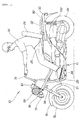
- Fig. 1 is a side view of the motor scooter type vehicle according to the present invention.
- the motor scooter type vehicle 10 has a basic structure in which a steering handle 13 is steerably attached to a head pipe 12 at a front portion of a vehicle body frame 11, and a front wheel 15 and a front fender 16 are mounted to a front fork 14 connected to the steering handle 13.
- the motor scooter type vehicle 10 is a light vehicle on which two persons can ride, in which a separate frame 18 is mounted to the vehicle body frame 11, a head light 19, direction indicator lamps 21 and the like are attached to the separate frame 18, steps 22 are attached to down tubes 17, a power unit 23 is vertically swingably mounted to a rear portion of the vehicle frame 11, a rear wheel 24 is mounted on the rear side of the power unit 23, a driver's seat 25 is provided on the skewly upper side (toward the front side) of the rear wheel 24, and a combined passenger seat and seat back 26 is provided on the upper side of the rear wheel 24.
- numeral 27 denotes a steering handle post cover
- 28 denotes a side cover
- 29 denotes a rear cushion
- 31 denotes a stand
- 32 denotes a grab rail.
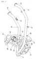
- Fig. 2 is a side view of a motor scooter type vehicle according to the present invention which has been modified to a one-person-riding type, and the basic constitution of which is the same as in Fig. 1, so that the same symbols as above are used again and the description of the basic constitution is omitted.
- the above-mentioned combined passenger seat and seat back 26 is erected to be a backrest, or seat back, for the driver M.
- the figure shows the condition where a luggage 33 such as a tent is mounted on a front portion of the separate frame 18.
- this motor scooter type vehicle is characterized in that not only the steering handle 13 and the grab rails 32 but also the separate frame 18, the down tubes 17, lower pipes 34 extended from the down tubes 17, and rear frames 35 are exposed.
- a vehicle body frame is covered with a vehicle body cover so that most of the vehicle body frame is unexposed.
- a vehicle body cover so that most of the vehicle body frame is unexposed.
- most of the vehicle body frame is exposed, to display a novel characteristic feature on an appearance basis.
- FIG. 3 is a perspective view of steps adopted in the present invention.
- a right step 22R (R is a suffix indicating "right", here and hereinafter) on which the driver puts his right foot is comprised of a receiving plate 36, a stay 37 for connecting the receiving plate 36 to the down tube, a pipe 38 set along the periphery of the receiving plate 36, and a rubber plate 39 attached to the top face of the receiving plate 36.
- a soft resin plate may be used in place of the rubber plate 39.
- a left step 22L (L is a suffix indicating "left", here and hereinafter) on which the driver puts his left foot is the same in structure with the right step 22R, so that the same symbols as above are again used, and description thereof is omitted.
- Fig. 4 is a sectional view taken along line 4-4 of Fig. 3, showing that the rubber plate 39 comprises so-called split-tip bulb form hook projections 41 ⁇ ⁇ ⁇ (the symbol ⁇ ⁇ ⁇ indicates a plurality, here and hereinafter) and that the rubber plate 39 can be detachably attached to the receiving plate 36.
- steps assembled from steel plates by welding have also been adopted, but they are inferior to the die-cast aluminum steps from the viewpoints of weight, appearance, and the like.
- the steps 22 (22L, 22R) according to the present invention have the structure in which the pipe 38 is set along the periphery of the receiving plate 36, so that the pipe 38 functions as a reinforcement for the receiving plate 36, and the receiving plate 36 can be reduced in plate thickness and weight.
- the steps 22L and 22R can be reduced in weight and cost, as compared with the die-cast steps, while maintaining the appearance quality thereof.
- the steps 22 according to the present invention can be manufactured by subjecting a steel member to plastic working such as cutting, bending, drawing, etc. and welding the plastically worked steel semi-products; therefore, there is no need for dies or a die casting machine, and the production cost of the steps 22 can be lowered, as compared to that of the die-cast steps.
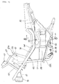
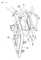
- Fig. 5 is an exploded view of the vehicle body frame of the motor scooter type vehicle according to the present invention.
- the vehicle body frame 11 is comprised of a main frame 43 extended from the head pipe 12 and being V- or U-shaped in side view, the rear frames 35 constituting or extended rearwards from a rear portion of the main frame 43, the down tubes 17 extended downwards from the head pipe 12, lower pipes 34 extended substantially horizontally from the down tubes 17, center frames 44 rising from the rear ends of the lower pipes 34, and stays 45 for connection between the center frames 44 and the rear frames 35.
- the lower pipes 34 are each provided with cover fixing plates 46, 46.
- a simple-formed frame separatedly shown on the upper side in the figure is the separate frame 18.
- the separate frame 18 comprises a luggage receiving pipe 47 provided on the upper surface of a front portion thereof, a lamp support bracket 48 and a luggage hook 49 provided on the lower surface of a front portion thereof, cover fixing plates 51, 51 provided on the lower surface thereof, a bracket 53 provided on the upper surface of a front portion thereof, the bracket 53 being provided with holes 52, 52, and a U-shaped bracket 54 provided on the lower surface of a rear portion thereof.
- a front portion plate 57 provided with holes 56, 56 is provided on the front surface of the head pipe 12, and a rear portion plate 59 provided with a hole 58 is provided on the upper surface of a front portion of each rear frame 35.
- the rear portion plate 59 is disposed in the vicinity of a connection portion 55 between the main frame 43 and the rear frames 35.
- the connection portion 55 is a portion where the single main frame 43 and the two rear frames 35 are collected, and is high in rigidity. Provision of the rear portion plate 59 in the vicinity (in this embodiment, on the rear side) of the high-rigidity connection portion 55 is advantageous on an strength basis in supporting the separate bracket 18.
- the bracket 53 is fastened to the front portion plate 57 with bolts, and the U-shaped bracket 54 is fastened to the rear portion plate 59 with a bolt, whereby the separate frame 18 can be integrated to the head pipe 12 and the main frame 43.
- the form after the integration will be described referring to Fig. 7.
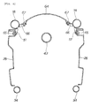
- Fig. 6 is an illustration of the functions of the separate frame according to the present invention.
- the separate frame 18 is a pipe frame being U-shaped in plan view, and is a useful frame such that the direction indicator lamps 21, 21 and the head light 19 can be attached to the lamp support bracket 48, a meter unit 61 can be attached to the luggage receiving pipe 47, and a parking brake lever 63 and the like can be attached to a right portion of the bracket 53 through a stay 62.
- Fig. 7 is a side view of the vehicle body frame of the motor scooter type vehicle according to the present invention, showing the condition after the separate frame 18 is mounted onto the head pipe 12 and the rear frames 35, a center cover portion 64 comprising the steering handle post cover 27 integrally is coveringly mounted, a side cover 28 is mounted between the separate frame 18 and the lower pipe 34 with bolts 65 ⁇ ⁇ ⁇ , and the step 22L is attached to the lower pipe 34.
- the front surface of the steering handle post cover 27 is a flat surface as shown in the figure, i.e., a structure is adopted in which a front luggage carrier space can be secured sufficiently.
- a shelf portion 27a lowered by a step is formed at a rear upper portion of the steering handle post cover 27, so as to attach a combination lock device 70 (a detailed structure thereof will be described later) to the shelf portion 27.
- Fig. 8 is a sectional view taken along line 8-8 of Fig. 7, showing the condition after the center cover portion 64 is attached to cover fixing plates 66, 66 appended to the separate frame 18 with bolts 67, 67, and the side covers 28, 28 are attached to the cover fixing plates 51, 51 with bolts 65, 65.
- the present invention is characterized in that the separate frame 18, 18 (two symbols are used for convenience, though the separate frame 18 is a single body) is disposed on the upper side of the left and right lower pipes 34, 34, and the center cover portion 64 and the side covers 28, 28 are mounted by cleverly utilizing the separate frame 18, 18.
- the separate frame 18, 18 can be utilized for luggage fixation and the like.
- the center cover portion 64 and the side covers 28, 28 (these are referred to as the vehicle body cover) are disposed on the inner side of the separate frame 18, 18 and the left and right lower pipes 34, 34, the vehicle body cover as a whole can be made compacter, and the vehicle body cover can be reduced in weight and cost.
- box-like vehicle body cover is surrounded with the separate frame 18, 18 and the lower pipes 34, 34, it is possible to form a pipe-framed container-like outside shape as a whole, and appearance quality can be enhanced.
- Fig. 9 is an exploded perspective view of the combination lock device according to the present invention.
- the combination lock device 70 is comprised of a combination lock unit 73 comprising a key hole 71, switches (not shown because they are incorporated) and a pin projecting/retracting mechanism (not shown because it is incorporated) for projecting and retracting a lock pin 72; a unit support bracket 74 for attaching the combination lock unit 73 to the head pipe 12; a gate form bracket 76 to be fixed to the unit support bracket 74 with three small screws 75 ⁇ ⁇ ⁇ ; a shutter housing 78 to be fixed to the gate form bracket 76 with bolts 77, 77 which are screwed from the lower side; and a lock plate 81 fixed to a steering shaft 79 by welding.
- the lock plate 81 is provided with two lock holes 82A, 82B.
- the head pipe 12 is a non-rotable member, while the steering shaft 79 is a rotatable member, so that the steering handle can be locked by hooking the side of the steering shaft 79 to the head pipe 12.
- the combination lock device 70 according to the present invention is based on this principle.
- the combination unit 73 is fixed by bolts 83, 83 to the unit support bracket 74 provided on the back surface of the head pipe 12, and the gate form bracket 76 is mounted in the manner of covering the combination lock unit 73.
- the shutter housing 78 is preliminarily fixed to the gate form bracket 76 with bolts.
- Fig. 10 is a perspective view of the combination lock device according to the present invention.
- the combination lock device is characterized in that the shutter housing 78 is placed on the gate form bracket 76 so mounted as to cover the combination lock unit 73, and the shutter housing 78 is fixed by bolts 77, 77 which are fastened from the lower side.
- the head pipe 12 and the steering shaft 79 are covered with the steering handle post cover 27.
- most of the combination lock device 70 in Fig. 10 is covered with the steering handle post cover, leaving only the shutter housing 78 exposed. Since the bolts 77, 77 are not visible and the head portions of the bolts 77, 77 are located on the lower side, it is not easy to slacken the bolts 77, 77 from the upper side. As a result, it is difficult to detach the shutter housing 78, and there is no fear that the combination lock unit 73 might be damaged.
- Figs. 11 (a) to (c) are diagrams for comparison between new and conventional combination lock devices, in which (a) and (b) are function diagrams of the combination lock device according to the present invention, and (c) is a function diagram of a conventional combination lock device.
- Fig. 12 is a perspective view of a rear luggage carrier according to the present invention.
- the driver's seat 25 becomes a seat with a backrest.
- the angle of the combined passenger seat and seat back 26 can be changed by operating a lock lever 86 annexed to a connection link 85.
- FIG. 1 shows that a rear luggage carrier 87 and the grab rails 32 are attached to the rear frame 35.
- the rear luggage carrier 87 is composed of a corrugated plate of a resin or a light metal. As compared with a flat plate, the corrugated plate makes it possible to markedly increase the section modulus and, hence, to mount more luggage thereon.
- Fig. 13 is a sectional view taken along line 13 of Fig. 12, and shows the condition where an inside rail 88 is disposed in parallel to the rear frame 35 and on the vehicle body center side (on the left side in the figure) relative to the rear frame 35 so that a leg portion 89 extended downwards from rear luggage carrier 87 can be mounted on the inside rail 88.
- a triangular bracket 91 is extended from the round pipe form rear frame 35 toward the vehicle body center side, a top face plate 92 of the triangular bracket 91 is provided with two holes 93 and 94, and the rear luggage carrier 87 is fixed to the hole 93 on the inner side with a bolt 95.
- a base 96 of the grab rail 32 is attached to the hole 94 on the outer side with a bolt 97, as shown.
- the top face plate 92 of the triangular bracket 91 is set to be higher than the top surface of the rear frame 35 by a distance t.
- the distance t is 1 to 2 mm. The reason why such a structure is adopted is as follows.
- the lower ends of the grab rails 32 are brought into contact with the rear frame 35, and the content portions are welded.
- the grab rails 32 are detachable members and are fastened in a bolt-on type, the fastened portions appear to the outside.
- the base 96 is extended from the lower end of the grab rail 32, and the tip of the base 96 is inserted to the lower side of the rear luggage carrier 87 and is thereafter bolted to the triangular bracket 91.
- the grab rails 32 are detachable, and are good in appearance quality, since the fastened portions are invisible.
- the flexure has been calculated by regarding the base 96 as a cantilever, and the above-mentioned distance t has been set to a value in excess of the estimated flexure, to thereby prevent the interference.
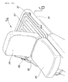
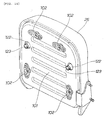
- Fig. 14 is a view along arrow 14 of Fig. 12, showing the back surface (bottom surface) structure of the combined passenger seat and seat back 26.
- the combined passenger seat and seat back 26 is characterized in that a seat bottom plate (symbol 98 in Fig. 17 which will be described later) surrounding a cushioning material is further surrounded with a back plate 101, and a total of four T-shaped hooks 102 ⁇ ⁇ ⁇ are provided, for example, at upper left and right positions and lower left and right positions of the back plate 101.
- the back plate 101 When no luggage is mounted on a rear portion of the vehicle body, the back plate 101 functions as an appearance member, so that the back plate 101 is composed of a beautiful plate member. Moreover, since bending forces due to the T-shaped hooks 102 are exerted on the back plate 101, it is necessary to enhance the rigidity of the back plate 101. In view of this, the back plate 101 is composed of a corrugated plate, so as to earn a section modulus.
- the back plate 101 is suitably composed of a steel plate, a resin plate or the like, and since it is an appearance member, it is subjected to a surface treatment such as coating, plating, coloring, etc.
- Fig. 15 is a back view of the motor scooter type vehicle according to the present invention, showing the condition after a bag 103 and skate boards 104, 104 are mounted on the rear luggage carrier 87, and are fixed with a rope 105 hooked on the grab rails 32 and the combined passenger seat and seat back 26 (the T-shaped hooks not shown here).
- the luggage carrier 87 When the horizontal rear luggage carrier 87 is only used, the luggage will be moved forwards or rearwards upon a sudden braking or the like. According to the present invention, the presence of the combined passenger seat and seat back 26 prevents the luggage from being moved forwards, and, with the rope 105 hooked on the T-shaped hooks (not shown here), the luggage can be prevented from being moved rearwards.
- a luggage stocker 106 is provided at the right side of the rear luggage carrier 87; the luggage stocker 106 will be described in detail later.
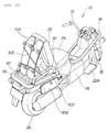
- Fig. 16 is an illustration of a seat slide mechanism adopted in the present invention.
- the driver's seat 25 in the present invention can be changed in its position in the front-rear direction according to the driver's taste, and, for achieving the positional change, the seat slide mechanism 110 is provided at a rear portion of the vehicle body.
- the seat slide mechanism 110 is comprised of left and right seat rails 111L and 111R, left and right sliders 112L and 112R mounted to the seat rails 111L and 111R so as to be slidable in the front-rear direction, a slide lock serrate member 113 provided on the right slider 112R, an operating lever 114 for switching between a locked condition and an unlocked condition by rotating the serrate member 113, front and rear cross members 115 and 116 for connection between the left and right sliders 112L and 112R, the connection link 85 extended from a rear portion of the right slider 112R, and a link 117 extended from a rear portion of the left slider 112L.
- the left and right sliders 112L and 112R can be freely moved in the front-rear direction.
- the driver's seat 25 is fixed to the left and right sliders 112L and 112R, and the combined passenger seat and seat back 26 is fixed to the connection link 85 and the link 117.
- the driver can fix the driver's seat 25 and the combined passenger seat and seat back 26 at the respective positions.
- the driver or the passenger can set the combined passenger seat and seat back 26 into a horizontal state, as shown in the figure.
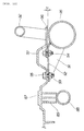
- Fig. 17 is a sectional view (the grab rails are omitted) taken along line 17-17 of Fig. 16.
- the combined passenger seat and seat back 26 is a structure which is composed basically of a cushioning material 118 such as sponge, a skin 119, and the seat bottom plate 98, wherein a reinforcing frame 121 is set along the seat bottom plate 98, legs 122, 122 are extended from the seat bottom plate 98, and pads 123, 123 are attached to the tip ends (the lower ends, in the figure) of the legs 122, 122.
- the reinforcing frame 121 is connected to the link 117 shown in Fig. 16.
- the seat bottom plate 98 is provided with edge portions 124, 124 swelled to the lower side and a recessed portion 125 at a central portion thereof, in order to provide the seat with a feeling of thickness.
- the recessed portion 125 and the reinforcing frame 121 are collectively covered with the back plate 101, thereby enhancing the appearance quality when the combined passenger seat and seat back 26 is erected.
- the above-mentioned legs 122, 122 are projected at positions coinciding with the left and right inside rails 88, 88. This ensures that the weight of the passenger can be directly supported by the inside rails 88, 88 through the legs 122, 122 and the leg portions 89, 89 of the rear luggage carrier 87. Only compressive forces are exerted on the leg portions 89, 89 of the rear luggage carrier 87, and no bending force is exerted on the rear luggage carrier 87.
- the T-shaped hooks 102, 102 are set at such a height that a gap g can be secured above the rear luggage carrier 87.
- the gap g is 4 to 5 mm.
- the luggage carrier may be provided with tiltable hooks or projectable/retractable hooks.
- Such hooks can be contained when not used, so that a good appearance can be maintained, and, since the hooks are drawn out when used, the hooks can be made large, thereby earning the margins for hooking a rope thereon.
- the rear luggage carrier 87 may be scratched and the hooks themselves may be damaged.
- the T-shaped hooks 102 have been adopted. With the T shape, it is possible to secure the horizontal bar of T as left and right two claws, with the vertical bar of T as a center, and the rope can be satisfactorily hooked on the vertical bar and the left and right two claws. Namely, the T-shaped hooks can earn the margins for hooking a rope thereon notwithstanding the small size thereof, as compared with L-shaped hooks.
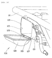
- Fig. 18 is a perspective view of the luggage stocker according to the present invention.
- the luggage stocker 106 is comprised of a container 126 having a lateral opening 125, a flange portion 127 projecting from an edge of the opening 125 of the luggage stocker container 126 toward the front side of the vehicle body, a lid 128 for closing the opening 125, and hinges 129, 129 for connecting the lid 128 to the lower edge of the opening 125.
- the luggage stocker 106 is mounted to the vehicle body by attaching the container 126 to the rear frame 35.
- Fig. 19 is a view along arrow 19 of Fig. 18, showing that a secondary air control valve 131 is arranged behind the flange portion 127 of the luggage stocker 106.
- the secondary air control valve 131 is an important apparatus for supplying an appropriate quantity of air into an exhaust system of an engine, so as to promote combustion of an exhaust gas and to cause combustion of unburned gas components remaining in the exhaust gas, thereby contriving clarification of the exhaust gas.
- the important secondary air control valve 131 is generally contained in the inside of a vehicle body cover.
- the secondary air control valve 131 is not contained in the inside of the vehicle body cover such as the side cover.
- the flange portion 127 is projected from the luggage stocker 106 disposed in the vicinity of the secondary air control valve 131, so as to protect the secondary air control valve 131 with the flange portion 127.
- it is unnecessary to newly provide an exclusive-use protective cover, a mount bracket or brackets and small screws, and a reduction in the number of component parts can be contrived.
- the secondary air control valve 131 is disposed in the outside of the vehicle body cover, maintenance and replacement of the secondary air control valve 131 can be carried out by only detaching the luggage stocker 106.
- Figs. 20 (a) and (b) are side views showing the air cleaner and the power unit, in which (a) pertains to a comparative example, and (b) pertains to an embodiment of the present invention.
- an air cleaner 211 is disposed on the upper side of a power unit 210, and an intake port of the air cleaner 211 is covered with a vehicle body cover 212.
- Motor scooter type vehicles generally adopt this type of structure.
- an air cleaner 132 is disposed on the power unit 23, and an intake port 133 of the air cleaner 132 is not covered with a vehicle body cover 134.
- the vehicle body cover 134 can be reduced in size, but, on the other hand, foreign matters such as stones, sand, mud, etc. flying from the viewer's side are liable to penetrate into the intake port 133, so that there is need for a countermeasure against the penetration.
- it is attempted to provide an intake port cover as the countermeasure it is necessary to provide a cover support bracket for the intake port cover.
- adoption of the cover support bracket is unfavorable because it leads to an increase in the number of component parts.
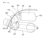
- Fig. 21 illustrates the point in mounting an intake port cover according to the present invention.
- the present inventors have tried to utilize a lid 128 of the power unit 23 which is located in the vicinity of the intake port 133.
- a case 135 of the air cleaner 132 is provided with a recessed portion 136 which is recessed toward the depth side of the drawing, and the recessed portion 136 is provided with screw holes 137, 137.
- the intake port cover 140 is comprised of a circular plate portion 141 roughly the same in shape with the lid 128, a cover portion 142 projected from the circular plate portion 141, and bolt holes 143, 143 provided at the tip of the cover portion 142.
- X-X shown at a right lower portion of the figure indicates section X-X of the cover portion 142
- Y-Y indicates section Y-Y of the cover portion 142, which show that a base portion of the cover portion 142 is a duct portion.
- cooling air can be led to the power unit 23.
- the intake port cover 140 is fixed with bolts 144, 144 by superposing the bolt holes 143, 143 on the screw holes 137, 137, and the circular plate portion 141 is co-fastened and fixed together with the lid 128 by bolts 145 ⁇ ⁇ ⁇ which have fastened the lid 128.
- Fig. 22 shows the condition where the intake port cover according to the present invention is mounted in position, and shows that the intake port cover 140 is mounted by bridging it between the power unit 23 and the air cleaner 132, without using a bracket for exclusive use.
- cover portion 142 of the intake port cover 140 is fitted into the recessed portion 136, resulting in that the cover portion 142 is flush with the case 135 of the air cleaner 132, which provides a good appearance quality.
- Fig. 23 is a perspective view of the vehicle body frame according to the present invention, showing that the main frame 43 is extended from the head pipe 12, and the two rear frames 35, 35 generally called seat rails are extended from the main frame 43.
- Symbol 147 denotes a fuel tank which is mounted to the vehicle body frame 11.
- the separate frame according to the present invention may be any member that can later be mounted to the existing main frame or to the main frame and the rear frames by bolts or the like, and the shape of the separate frame is arbitrary.
- the vehicle component parts to be attached to the separate frame can be selected freely.
- the present invention constituted as described above, displays the following effects.
- the separate frame has its front portion attached to the head pipe and has its rear portion attached to a portion in the vicinity of the engagement portion between the main frame and the rear frames, so that a luggage mounting space can be secured, without specially reinforcing the separate frame.
- the left-right width of the separate frame is substantially equal to that of the left and right two lower pipes, a rectangular frame can be constituted of the separate frame and the lower pipes, thereby enhancing the appearance quality.
- the vehicle body cover can be constituted by only attaching flat plate-like covers.
- the cover can be easily made lighter in weight and compacter, while maintaining the appearance quality.
- a small-type vehicle having a new form can be created by only diverting a vehicle body frame of a conventional full-cover type motor scooter and adding the separate frame to the vehicle body frame.
Landscapes
- Engineering & Computer Science (AREA)
- Mechanical Engineering (AREA)
- Automatic Cycles, And Cycles In General (AREA)
- Vehicle Step Arrangements And Article Storage (AREA)
- Seats For Vehicles (AREA)
Abstract
Description
- The present invention relates to an improvement in a motorcycle.
- Conventionally, a variety of motorcycles have been put to practical use (see, for example, Patent Reference 1).
- Japanese Utility Model Laid-open No. Sho 58-181687 (Fig. 2).
- Fig. 24 is a copy of Fig. 2 of
Patent Reference 1. As shown in the figure, there has been known a small-type motorcycle in which a luggage can be mounted on the upper side of an upper frame 20 extending forwards from a seat 2, a separate frame is extended forwards from the upper side of the upper frame 20 to be afront carrier 12, and accessories such as ahead light 18 are attached to thefront carrier 12. - In the case of such a constitution, in a medium-or larger-type motorcycle, the vehicle body extends in the front-rear direction, so that it is necessary to secure the strength of the vehicle body frame, in order to ensure that a luggage can be mounted on the upper frame.
- In a low floor type vehicle represented by a motor scooter type vehicle comprising a straddle portion, also, it is desired to provide the straddle portion with a luggage mount portion.
- On the other hand, in order to cope with the increase in the diversity of people's taste while using a single main frame, there is a demand for creating a variety of outside shapes.
- Accordingly, it is an object of the present invention to provide a motorcycle which makes it possible to more easily secure the strength of a vehicle body frame and to enhance the luggage mounting performance at a straddle portion and the diversity of shape of a main frame.
- In order to attain the above object, according to
claim 1, there is provided: - a motorcycle comprising:
- a vehicle body frame which comprises a main frame extended from a head pipe, rear frames extended rearwards from the main frame, left and right two down tubes extended downwards from the head pipe, and lower pipes extended rearwards from the down tubes, the lower pipes being connected to a center frame rising upwards, and the center frame being connected to the rear frames; and
- a separate frame which is separate from the vehicle body frame, is extended rearwards along the main frame from the front side of the head pipe, has a left-right width substantially equal to that of the left and right two lower pipes, has a front portion attached to the head pipe, and has a rear portion attached to a portion in the vicinity of an engagement portion between the main frame and the rear frames, whereby the separate frame is mounted to the vehicle body frame.
-
- Since the separate frame has its front portion attached to the head pipe and has its rear portion attached to a portion in the vicinity of the engagement portion between the main frame and the rear frames, a luggage space can be secured without specially reinforcing the separate frame.
- In addition, since the separate frame has its left-right width made to be substantially equal to that of the left and right two lower pipes, a rectangular frame body can be constituted of the separate frame and the lower pipes, and appearance quality can be enhanced.
- With a rectangular frame thus provided, it is possible to constitute a vehicle body cover by only attaching flat plate-like covers to the frame. Thus, it is possible to easily render the cover lighter in weight and compacter while maintaining the appearance quality.
- Furthermore, by only diverting a vehicle body frame of a conventional full-cover type motor scooter and adding a separate frame to the vehicle body frame, it is possible to create a small-type vehicle having a new form.
-
- Fig. 1 is a side view of a motor scooter type vehicle according to the present invention
- Fig. 2 is a side view of the motor scooter type vehicle according to the present invention which has been modified into a one-person-riding type
- Fig. 3 is a perspective view of steps adopted in the present invention
- Fig. 4 is a sectional view taken along line 4-4 of Fig. 3
- Fig. 5 is an exploded view of a vehicle body frame of the motor scooter type vehicle according to the present invention
- Fig. 6 is an illustration of functions of a separate frame according to the present invention
- Fig. 7 is a side view of the vehicle body frame of the motor scooter type vehicle according to the present invention
- Fig. 8 is a sectional view taken along line 8-8 of Fig. 7
- Fig. 9 is an exploded perspective view of a combination lock device according to the present invention
- Fig.10 is a perspective view of the combination lock device according to the present invention
- Fig. 11 is views for comparison between the new combination lock device according to the present invention and a conventional combination lock device
- Fig. 12 is a perspective view of a rear luggage carrier according to the present invention
- Fig. 13 is a sectional view taken along
line 13 of Fig. 12 - Fig. 14 is a view along
arrow 14 of Fig. 12 - Fig. 15 is a back view of the motor scooter type vehicle according to the present invention
- Fig. 16 is an illustration of a seat slide mechanism adopted in the present invention
- Fig. 17 is a sectional view (grab rails are omitted) taken along line 17-17 of Fig. 16
- Fig. 18 is a perspective view of a luggage stocker according to the present invention
- Fig. 19 is a view along
arrow 19 of Fig. 18 - Fig. 20 is a side view of an air cleaner and a power unit
- Fig. 21 is an illustration of the point in mounting an intake port cover according to the present invention
- Fig. 22 is an illustration of the condition where the intake port cover according to the present invention is mounted
- Fig. 23 is a perspective view of a vehicle body frame according to the present invention
- Fig. 24 is a copy of Fig. 1 of
Patent Reference 1 -
- A mode for carrying out the present invention will be described below, based on the accompanying drawings. Incidentally, the drawings are to be looked at according to the posture of symbols.
- In this carrying-out mode, a motor scooter type vehicle will be described as an example of a low floor type vehicle. However, the low floor type vehicle may be any of a motorcycle, a motor tricycle and a four-wheel vehicle, inasmuch as it is a vehicle in which a front wheel or wheels and a rear wheel or wheels are provided at front and rear portions of a vehicle body frame, a main frame extending rearwards from a head pipe, of the vehicle body frame, is V- or U-shaped in side view, and the driver can easily straddle the main frame.
- Fig. 1 is a side view of the motor scooter type vehicle according to the present invention. The motor
scooter type vehicle 10 has a basic structure in which asteering handle 13 is steerably attached to ahead pipe 12 at a front portion of avehicle body frame 11, and afront wheel 15 and afront fender 16 are mounted to afront fork 14 connected to thesteering handle 13. - The motor
scooter type vehicle 10 is a light vehicle on which two persons can ride, in which aseparate frame 18 is mounted to thevehicle body frame 11, ahead light 19,direction indicator lamps 21 and the like are attached to theseparate frame 18,steps 22 are attached to downtubes 17, apower unit 23 is vertically swingably mounted to a rear portion of thevehicle frame 11, arear wheel 24 is mounted on the rear side of thepower unit 23, a driver'sseat 25 is provided on the skewly upper side (toward the front side) of therear wheel 24, and a combined passenger seat andseat back 26 is provided on the upper side of therear wheel 24. - In the figure,
numeral 27 denotes a steering handle post cover, 28 denotes a side cover, 29 denotes a rear cushion, 31 denotes a stand, and 32 denotes a grab rail. - Fig. 2 is a side view of a motor scooter type vehicle according to the present invention which has been modified to a one-person-riding type, and the basic constitution of which is the same as in Fig. 1, so that the same symbols as above are used again and the description of the basic constitution is omitted. In this case, the above-mentioned combined passenger seat and
seat back 26 is erected to be a backrest, or seat back, for the driver M. Besides, the figure shows the condition where aluggage 33 such as a tent is mounted on a front portion of theseparate frame 18. - Furthermore, this motor scooter type vehicle is characterized in that not only the
steering handle 13 and thegrab rails 32 but also theseparate frame 18, thedown tubes 17,lower pipes 34 extended from thedown tubes 17, andrear frames 35 are exposed. - In a conventional motor scooter type vehicle, ordinarily, a vehicle body frame is covered with a vehicle body cover so that most of the vehicle body frame is unexposed. On the contrary, according to the present invention, most of the vehicle body frame is exposed, to display a novel characteristic feature on an appearance basis.
- Fig. 3 is a perspective view of steps adopted in the present invention. A
right step 22R (R is a suffix indicating "right", here and hereinafter) on which the driver puts his right foot is comprised of areceiving plate 36, astay 37 for connecting thereceiving plate 36 to the down tube, apipe 38 set along the periphery of thereceiving plate 36, and arubber plate 39 attached to the top face of thereceiving plate 36. A soft resin plate may be used in place of therubber plate 39. - A
left step 22L (L is a suffix indicating "left", here and hereinafter) on which the driver puts his left foot is the same in structure with theright step 22R, so that the same symbols as above are again used, and description thereof is omitted. - Fig. 4 is a sectional view taken along line 4-4 of Fig. 3, showing that the
rubber plate 39 comprises so-called split-tip bulbform hook projections 41 · · · (the symbol · · · indicates a plurality, here and hereinafter) and that therubber plate 39 can be detachably attached to the receivingplate 36. - Conventionally, flat plate type steps have been formed by aluminum die casting or the like, in some cases. While die-cast products are preferred due to good appearance thereof, a reduction in cost is also expected in the cases of medium- and smaller-type vehicles.
- In view of this, steps assembled from steel plates by welding have also been adopted, but they are inferior to the die-cast aluminum steps from the viewpoints of weight, appearance, and the like.
- In relation to this, the steps 22 (22L, 22R) according to the present invention have the structure in which the
pipe 38 is set along the periphery of the receivingplate 36, so that thepipe 38 functions as a reinforcement for the receivingplate 36, and the receivingplate 36 can be reduced in plate thickness and weight. As a result, thesteps - In addition, the
steps 22 according to the present invention can be manufactured by subjecting a steel member to plastic working such as cutting, bending, drawing, etc. and welding the plastically worked steel semi-products; therefore, there is no need for dies or a die casting machine, and the production cost of thesteps 22 can be lowered, as compared to that of the die-cast steps. - Fig. 5 is an exploded view of the vehicle body frame of the motor scooter type vehicle according to the present invention. The
vehicle body frame 11 is comprised of amain frame 43 extended from thehead pipe 12 and being V- or U-shaped in side view, the rear frames 35 constituting or extended rearwards from a rear portion of themain frame 43, thedown tubes 17 extended downwards from thehead pipe 12,lower pipes 34 extended substantially horizontally from thedown tubes 17, center frames 44 rising from the rear ends of thelower pipes 34, and stays 45 for connection between the center frames 44 and the rear frames 35. Thelower pipes 34 are each provided withcover fixing plates - A simple-formed frame separatedly shown on the upper side in the figure is the
separate frame 18. - The details of the
separate frame 18 will be described below, whereas the details of thevehicle body frame 11 will be described referring to Fig. 23 later. - The
separate frame 18 comprises aluggage receiving pipe 47 provided on the upper surface of a front portion thereof, alamp support bracket 48 and aluggage hook 49 provided on the lower surface of a front portion thereof,cover fixing plates bracket 53 provided on the upper surface of a front portion thereof, thebracket 53 being provided withholes U-shaped bracket 54 provided on the lower surface of a rear portion thereof. - On the other hand, a
front portion plate 57 provided withholes head pipe 12, and arear portion plate 59 provided with ahole 58 is provided on the upper surface of a front portion of eachrear frame 35. - The
rear portion plate 59 is disposed in the vicinity of aconnection portion 55 between themain frame 43 and the rear frames 35. Theconnection portion 55 is a portion where the singlemain frame 43 and the tworear frames 35 are collected, and is high in rigidity. Provision of therear portion plate 59 in the vicinity (in this embodiment, on the rear side) of the high-rigidity connection portion 55 is advantageous on an strength basis in supporting theseparate bracket 18. - The
bracket 53 is fastened to thefront portion plate 57 with bolts, and theU-shaped bracket 54 is fastened to therear portion plate 59 with a bolt, whereby theseparate frame 18 can be integrated to thehead pipe 12 and themain frame 43. The form after the integration will be described referring to Fig. 7. - Fig. 6 is an illustration of the functions of the separate frame according to the present invention. The
separate frame 18 is a pipe frame being U-shaped in plan view, and is a useful frame such that thedirection indicator lamps head light 19 can be attached to thelamp support bracket 48, ameter unit 61 can be attached to theluggage receiving pipe 47, and aparking brake lever 63 and the like can be attached to a right portion of thebracket 53 through astay 62. - Besides, for example, when vehicle component parts such as the
direction indicator lamps 21, thehead light 19, themeter unit 61, and theparking brake lever 63 are preliminarily mounted onto the separate frame 18 (this process is called pre-assembling) and the pre-assembled product (the assembly shown in Fig. 6 itself) is mounted onto thehead pipe 12 and themain frame 43 shown in Fig. 5, it is possible to shorten the mounting time in an assembly line. - Fig. 7 is a side view of the vehicle body frame of the motor scooter type vehicle according to the present invention, showing the condition after the
separate frame 18 is mounted onto thehead pipe 12 and the rear frames 35, acenter cover portion 64 comprising the steering handlepost cover 27 integrally is coveringly mounted, aside cover 28 is mounted between theseparate frame 18 and thelower pipe 34 withbolts 65· · ·, and thestep 22L is attached to thelower pipe 34. - Incidentally, the front surface of the steering handle
post cover 27 is a flat surface as shown in the figure, i.e., a structure is adopted in which a front luggage carrier space can be secured sufficiently. - Besides, a
shelf portion 27a lowered by a step is formed at a rear upper portion of the steering handlepost cover 27, so as to attach a combination lock device 70 (a detailed structure thereof will be described later) to theshelf portion 27. - Fig. 8 is a sectional view taken along line 8-8 of Fig. 7, showing the condition after the
center cover portion 64 is attached to cover fixingplates separate frame 18 withbolts cover fixing plates bolts - If it is attempted to fix the
center cover portion 64 and the side covers 28, 28 to themain frame 43 with bolts, there would be need for large-scale cover mounting brackets. - In relation to this, the present invention is characterized in that the
separate frame 18, 18 (two symbols are used for convenience, though theseparate frame 18 is a single body) is disposed on the upper side of the left and rightlower pipes center cover portion 64 and the side covers 28, 28 are mounted by cleverly utilizing theseparate frame - As a result, the
separate frame center cover portion 64 and the side covers 28, 28 (these are referred to as the vehicle body cover) are disposed on the inner side of theseparate frame lower pipes - Furthermore, since the box-like vehicle body cover is surrounded with the
separate frame lower pipes - Besides, as is clear from the figure, large-scale cover mounting brackets are unnecessary, which enables a reduction in the production cost of the vehicle body frame.
- Next, a steering handle lock mechanism provided for an burglarproof purpose will be described. It should be noted here that, in the present invention, a so-called combination lock device comprising a steering handle lock mechanism incorporated in a combination switch is adopted.
- Fig. 9 is an exploded perspective view of the combination lock device according to the present invention. The
combination lock device 70 is comprised of acombination lock unit 73 comprising akey hole 71, switches (not shown because they are incorporated) and a pin projecting/retracting mechanism (not shown because it is incorporated) for projecting and retracting alock pin 72; aunit support bracket 74 for attaching thecombination lock unit 73 to thehead pipe 12; agate form bracket 76 to be fixed to theunit support bracket 74 with threesmall screws 75 · · · ; ashutter housing 78 to be fixed to thegate form bracket 76 withbolts lock plate 81 fixed to asteering shaft 79 by welding. - The
lock plate 81 is provided with twolock holes head pipe 12 is a non-rotable member, while the steeringshaft 79 is a rotatable member, so that the steering handle can be locked by hooking the side of the steeringshaft 79 to thehead pipe 12. Thecombination lock device 70 according to the present invention is based on this principle. - In order to attain the above principle, the
combination unit 73 is fixed bybolts unit support bracket 74 provided on the back surface of thehead pipe 12, and thegate form bracket 76 is mounted in the manner of covering thecombination lock unit 73. Preferably, theshutter housing 78 is preliminarily fixed to thegate form bracket 76 with bolts. - Fig. 10 is a perspective view of the combination lock device according to the present invention. The combination lock device is characterized in that the
shutter housing 78 is placed on thegate form bracket 76 so mounted as to cover thecombination lock unit 73, and theshutter housing 78 is fixed bybolts - As shown in Fig. 7, the
head pipe 12 and the steeringshaft 79 are covered with the steering handlepost cover 27. As a result, most of thecombination lock device 70 in Fig. 10 is covered with the steering handle post cover, leaving only theshutter housing 78 exposed. Since thebolts bolts bolts shutter housing 78, and there is no fear that thecombination lock unit 73 might be damaged. - Figs. 11 (a) to (c) are diagrams for comparison between new and conventional combination lock devices, in which (a) and (b) are function diagrams of the combination lock device according to the present invention, and (c) is a function diagram of a conventional combination lock device.
- (a) shows the condition after the steering
shaft 79 is turned counterclockwise substantially fully and alock pin 72 is inserted into thelock hole 82A. - (b) shows the condition after the steering
shaft 79 is turned clockwise substantially fully and thelock pin 72 is inserted into thelock hole 82B. In this case, it is a characteristic feature that the longitudinal axis of thecombination lock unit 73 extends in the direction orthogonal to the sheet of the drawing, the longitudinal direction is set substantially parallel to the steeringshaft 79, and thelock pin 72 is set horizontal. As a result, the distance L1 from the center of the steeringshaft 79 to the outside surface of thelock plate 81 can be set short. - (c) shows a conventional product in which
the
longitudinal axis 202 of a combination lock unit 201 (numerals of 200 plus something are used for a prior-art example and a comparative example, here and hereinafter) is set horizontal, alock pin 203 is moved vertically, and alock plate 204 is composed of a sector plate. The distance L2 from the center of asteering shaft 205 to the outside surface of thelock plate 204 is large. Moreover, since the areas in plan view of thelock plate 204 and thecombination lock unit 201 are large, it is difficult to arrange other apparatuses around thesteering shaft 205. -
- In this point, the product according to the present invention shown in (a) and (b) permits other apparatuses to be easily arranged around the steering
shaft 79. - Next, the details of the driver's
seat 25 and the combined passenger seat and seat back 26 according to the present invention will be described. - Fig. 12 is a perspective view of a rear luggage carrier according to the present invention. With the combined passenger seat and seat back 26 erected, the driver's
seat 25 becomes a seat with a backrest. The angle of the combined passenger seat and seat back 26 can be changed by operating alock lever 86 annexed to aconnection link 85. - In addition, the figure shows that a
rear luggage carrier 87 and the grab rails 32 are attached to therear frame 35. - The
rear luggage carrier 87 is composed of a corrugated plate of a resin or a light metal. As compared with a flat plate, the corrugated plate makes it possible to markedly increase the section modulus and, hence, to mount more luggage thereon. - Fig. 13 is a sectional view taken along
line 13 of Fig. 12, and shows the condition where aninside rail 88 is disposed in parallel to therear frame 35 and on the vehicle body center side (on the left side in the figure) relative to therear frame 35 so that aleg portion 89 extended downwards fromrear luggage carrier 87 can be mounted on theinside rail 88. - In addition, a
triangular bracket 91 is extended from the round pipe formrear frame 35 toward the vehicle body center side, atop face plate 92 of thetriangular bracket 91 is provided with twoholes 93 and 94, and therear luggage carrier 87 is fixed to the hole 93 on the inner side with abolt 95. Abase 96 of thegrab rail 32 is attached to thehole 94 on the outer side with abolt 97, as shown. - The
top face plate 92 of thetriangular bracket 91 is set to be higher than the top surface of therear frame 35 by a distance t. The distance t is 1 to 2 mm. The reason why such a structure is adopted is as follows. - Where a structure in which the round pipe
form grab rails 32 are attached directly to the round pipe formrear frame 35 is adopted, the lower ends of the grab rails 32 are brought into contact with therear frame 35, and the content portions are welded. Alternatively, where the grab rails 32 are detachable members and are fastened in a bolt-on type, the fastened portions appear to the outside. - In view of this, in the present invention, the
base 96 is extended from the lower end of thegrab rail 32, and the tip of thebase 96 is inserted to the lower side of therear luggage carrier 87 and is thereafter bolted to thetriangular bracket 91. The grab rails 32 are detachable, and are good in appearance quality, since the fastened portions are invisible. - It should be noted here that a force is naturally exerted on the
grab rail 32, resulting in that thebase 96 is flexed vertically. Thus, thebase 96 may interfere with therear frame 35. - In view of this, the flexure has been calculated by regarding the base 96 as a cantilever, and the above-mentioned distance t has been set to a value in excess of the estimated flexure, to thereby prevent the interference.
- Fig. 14 is a view along
arrow 14 of Fig. 12, showing the back surface (bottom surface) structure of the combined passenger seat and seat back 26. The combined passenger seat and seat back 26 is characterized in that a seat bottom plate (symbol 98 in Fig. 17 which will be described later) surrounding a cushioning material is further surrounded with aback plate 101, and a total of four T-shapedhooks 102 · · · are provided, for example, at upper left and right positions and lower left and right positions of theback plate 101. - When no luggage is mounted on a rear portion of the vehicle body, the
back plate 101 functions as an appearance member, so that theback plate 101 is composed of a beautiful plate member. Moreover, since bending forces due to the T-shapedhooks 102 are exerted on theback plate 101, it is necessary to enhance the rigidity of theback plate 101. In view of this, theback plate 101 is composed of a corrugated plate, so as to earn a section modulus. Theback plate 101 is suitably composed of a steel plate, a resin plate or the like, and since it is an appearance member, it is subjected to a surface treatment such as coating, plating, coloring, etc. - Fig. 15 is a back view of the motor scooter type vehicle according to the present invention, showing the condition after a
bag 103 and skateboards rear luggage carrier 87, and are fixed with arope 105 hooked on the grab rails 32 and the combined passenger seat and seat back 26 (the T-shaped hooks not shown here). - When the horizontal
rear luggage carrier 87 is only used, the luggage will be moved forwards or rearwards upon a sudden braking or the like. According to the present invention, the presence of the combined passenger seat and seat back 26 prevents the luggage from being moved forwards, and, with therope 105 hooked on the T-shaped hooks (not shown here), the luggage can be prevented from being moved rearwards. - Thus, a large amount of luggage can be stably mounted on the
rear luggage carrier 87 and transported. - A
luggage stocker 106 is provided at the right side of therear luggage carrier 87; theluggage stocker 106 will be described in detail later. - Fig. 16 is an illustration of a seat slide mechanism adopted in the present invention. The driver's
seat 25 in the present invention can be changed in its position in the front-rear direction according to the driver's taste, and, for achieving the positional change, theseat slide mechanism 110 is provided at a rear portion of the vehicle body. - The
seat slide mechanism 110 is comprised of left and right seat rails 111L and 111R, left andright sliders serrate member 113 provided on theright slider 112R, an operatinglever 114 for switching between a locked condition and an unlocked condition by rotating theserrate member 113, front andrear cross members right sliders connection link 85 extended from a rear portion of theright slider 112R, and alink 117 extended from a rear portion of theleft slider 112L. - The left and
right sliders - The driver's
seat 25 is fixed to the left andright sliders connection link 85 and thelink 117. As a result, by operating the operatinglever 114 so as to release the slide lock, moving the driver'sseat 25 and the combined passenger seat and seat back 26 to arbitrary positions in the front-rear direction and returning the operatinglever 114, the driver can fix the driver'sseat 25 and the combined passenger seat and seat back 26 at the respective positions. - Furthermore, by operating the
lock lever 86, the driver or the passenger can set the combined passenger seat and seat back 26 into a horizontal state, as shown in the figure. - Fig. 17 is a sectional view (the grab rails are omitted) taken along line 17-17 of Fig. 16. Describing first the sectional structure of the combined passenger seat and seat back 26, the combined passenger seat and seat back 26 is a structure which is composed basically of a
cushioning material 118 such as sponge, askin 119, and theseat bottom plate 98, wherein a reinforcingframe 121 is set along theseat bottom plate 98,legs seat bottom plate 98, andpads legs - Incidentally, the reinforcing
frame 121 is connected to thelink 117 shown in Fig. 16. - In addition, the
seat bottom plate 98 is provided withedge portions portion 125 at a central portion thereof, in order to provide the seat with a feeling of thickness. The recessedportion 125 and the reinforcingframe 121 are collectively covered with theback plate 101, thereby enhancing the appearance quality when the combined passenger seat and seat back 26 is erected. - The above-mentioned
legs legs leg portions rear luggage carrier 87. Only compressive forces are exerted on theleg portions rear luggage carrier 87, and no bending force is exerted on therear luggage carrier 87. - In addition, the T-shaped
hooks rear luggage carrier 87. The gap g is 4 to 5 mm. - In a small-type vehicle, generally, the luggage carrier may be provided with tiltable hooks or projectable/retractable hooks. Such hooks can be contained when not used, so that a good appearance can be maintained, and, since the hooks are drawn out when used, the hooks can be made large, thereby earning the margins for hooking a rope thereon.
- However, if the combined passenger seat and seat back 26 is tilted down by mistake under the condition where the tiltable hooks or projectable/retractable hooks are in a projected state, the
rear luggage carrier 87 may be scratched and the hooks themselves may be damaged. - In this relation, according to the present invention, fixed hooks are adopted. With the fixed hooks, it is unnecessary to take care of the situation that the driver or passenger might forget to contain the hooks, and there is no possibility that the related component parts might be damaged. Since the mounting space is limited, however, an increase in the size of the fixed hooks cannot be expected. In view of this, the T-shaped
hooks 102 have been adopted. With the T shape, it is possible to secure the horizontal bar of T as left and right two claws, with the vertical bar of T as a center, and the rope can be satisfactorily hooked on the vertical bar and the left and right two claws. Namely, the T-shaped hooks can earn the margins for hooking a rope thereon notwithstanding the small size thereof, as compared with L-shaped hooks. - Next, the details of the
luggage stocker 106 provided on the right lower side of the rear luggage carrier will be described. - Fig. 18 is a perspective view of the luggage stocker according to the present invention. The
luggage stocker 106 is comprised of acontainer 126 having alateral opening 125, aflange portion 127 projecting from an edge of theopening 125 of theluggage stocker container 126 toward the front side of the vehicle body, alid 128 for closing theopening 125, and hinges 129, 129 for connecting thelid 128 to the lower edge of theopening 125. - The
luggage stocker 106 is mounted to the vehicle body by attaching thecontainer 126 to therear frame 35. - Fig. 19 is a view along
arrow 19 of Fig. 18, showing that a secondaryair control valve 131 is arranged behind theflange portion 127 of theluggage stocker 106. The secondaryair control valve 131 is an important apparatus for supplying an appropriate quantity of air into an exhaust system of an engine, so as to promote combustion of an exhaust gas and to cause combustion of unburned gas components remaining in the exhaust gas, thereby contriving clarification of the exhaust gas. - In a motor scooter type vehicle, the important secondary
air control valve 131 is generally contained in the inside of a vehicle body cover. - In this embodiment, the secondary
air control valve 131 is not contained in the inside of the vehicle body cover such as the side cover. - In this case, in order to cope with stones flying from the exterior, it is necessary to cover the secondary
air control valve 131 with a protective cover for exclusive use. If this is adopted, it is necessary to provide the exclusive-use protective cover, a mount bracket or brackets and small screws, resulting in an increase in the number of component parts. - In the present invention, the
flange portion 127 is projected from theluggage stocker 106 disposed in the vicinity of the secondaryair control valve 131, so as to protect the secondaryair control valve 131 with theflange portion 127. As a result, it is unnecessary to newly provide an exclusive-use protective cover, a mount bracket or brackets and small screws, and a reduction in the number of component parts can be contrived. In addition, since the secondaryair control valve 131 is disposed in the outside of the vehicle body cover, maintenance and replacement of the secondaryair control valve 131 can be carried out by only detaching theluggage stocker 106. - Next, a protective cover for an intake port of an air cleaner will be described.
- Figs. 20 (a) and (b) are side views showing the air cleaner and the power unit, in which (a) pertains to a comparative example, and (b) pertains to an embodiment of the present invention.
- In the comparative example shown in (a), an
air cleaner 211 is disposed on the upper side of apower unit 210, and an intake port of theair cleaner 211 is covered with avehicle body cover 212. Motor scooter type vehicles generally adopt this type of structure. - In the embodiment shown in (b), an
air cleaner 132 is disposed on thepower unit 23, and anintake port 133 of theair cleaner 132 is not covered with avehicle body cover 134. On one hand, thevehicle body cover 134 can be reduced in size, but, on the other hand, foreign matters such as stones, sand, mud, etc. flying from the viewer's side are liable to penetrate into theintake port 133, so that there is need for a countermeasure against the penetration. When it is attempted to provide an intake port cover as the countermeasure, it is necessary to provide a cover support bracket for the intake port cover. However, adoption of the cover support bracket is unfavorable because it leads to an increase in the number of component parts. - Fig. 21 illustrates the point in mounting an intake port cover according to the present invention. The present inventors have tried to utilize a
lid 128 of thepower unit 23 which is located in the vicinity of theintake port 133. - Namely, a
case 135 of theair cleaner 132 is provided with a recessedportion 136 which is recessed toward the depth side of the drawing, and the recessedportion 136 is provided withscrew holes - The
intake port cover 140 is comprised of acircular plate portion 141 roughly the same in shape with thelid 128, acover portion 142 projected from thecircular plate portion 141, and boltholes cover portion 142. - Incidentally, X-X shown at a right lower portion of the figure indicates section X-X of the
cover portion 142, while Y-Y indicates section Y-Y of thecover portion 142, which show that a base portion of thecover portion 142 is a duct portion. Through the duct portion, cooling air can be led to thepower unit 23. - The
intake port cover 140 is fixed withbolts circular plate portion 141 is co-fastened and fixed together with thelid 128 bybolts 145 · · · which have fastened thelid 128. - Fig. 22 shows the condition where the intake port cover according to the present invention is mounted in position, and shows that the
intake port cover 140 is mounted by bridging it between thepower unit 23 and theair cleaner 132, without using a bracket for exclusive use. - In addition, the
cover portion 142 of theintake port cover 140 is fitted into the recessedportion 136, resulting in that thecover portion 142 is flush with thecase 135 of theair cleaner 132, which provides a good appearance quality. - Fig. 23 is a perspective view of the vehicle body frame according to the present invention, showing that the
main frame 43 is extended from thehead pipe 12, and the tworear frames main frame 43.Symbol 147 denotes a fuel tank which is mounted to thevehicle body frame 11. - Incidentally, the separate frame according to the present invention may be any member that can later be mounted to the existing main frame or to the main frame and the rear frames by bolts or the like, and the shape of the separate frame is arbitrary. Besides, the vehicle component parts to be attached to the separate frame can be selected freely.
- The present invention, constituted as described above, displays the following effects.
- According to
claim 1, the separate frame has its front portion attached to the head pipe and has its rear portion attached to a portion in the vicinity of the engagement portion between the main frame and the rear frames, so that a luggage mounting space can be secured, without specially reinforcing the separate frame. - In addition, since the left-right width of the separate frame is substantially equal to that of the left and right two lower pipes, a rectangular frame can be constituted of the separate frame and the lower pipes, thereby enhancing the appearance quality.
- With the rectangular frame, the vehicle body cover can be constituted by only attaching flat plate-like covers. The cover can be easily made lighter in weight and compacter, while maintaining the appearance quality.
- Furthermore, a small-type vehicle having a new form can be created by only diverting a vehicle body frame of a conventional full-cover type motor scooter and adding the separate frame to the vehicle body frame.
Claims (1)
- A motorcycle comprising:a vehicle body frame (11) which comprises a main frame extended from a head pipe, rear frames extended rearwards from said main frame, left and right two down tubes extended downwards from said head pipe, and lower pipes extended rearwards from said down tubes, said lower pipes being connected to a center frame rising upwards, and said center frame being connected to said rear frames; anda separate frame (18) which is separate from said vehicle body frame, is extended rearwards along said main frame from the front side of said head pipe, has a left-right width substantially equal to that of said left and right two lower pipes, has a front portion attached to said head pipe, and has a rear portion attached to a portion in the vicinity of an engagement portion between said main frame and said rear frames, whereby said separate frame is mounted to said vehicle body frame (11).
Applications Claiming Priority (2)
| Application Number | Priority Date | Filing Date | Title |
|---|---|---|---|
| JP2003132398A JP4153359B2 (en) | 2003-05-09 | 2003-05-09 | Motorcycle |
| JP2003132398 | 2003-05-09 |
Publications (2)
| Publication Number | Publication Date |
|---|---|
| EP1475299A1 true EP1475299A1 (en) | 2004-11-10 |
| EP1475299B1 EP1475299B1 (en) | 2006-05-24 |
Family
ID=32985688
Family Applications (1)
| Application Number | Title | Priority Date | Filing Date |
|---|---|---|---|
| EP04101915A Expired - Lifetime EP1475299B1 (en) | 2003-05-09 | 2004-05-04 | Motorcycle |
Country Status (5)
| Country | Link |
|---|---|
| US (1) | US7249648B2 (en) |
| EP (1) | EP1475299B1 (en) |
| JP (1) | JP4153359B2 (en) |
| CN (1) | CN100344495C (en) |
| TW (1) | TWI232824B (en) |
Cited By (1)
| Publication number | Priority date | Publication date | Assignee | Title |
|---|---|---|---|---|
| DE102011078268A1 (en) * | 2011-06-29 | 2013-01-03 | Bayerische Motoren Werke Aktiengesellschaft | Two-wheeler e.g. motor cycle, has seat comprising driver seat surface at front region and passenger seat surface at rear region, where passenger seat surface is arranged at two-wheeler in upwardly removable or upwardly pivotable manner |
Families Citing this family (11)
| Publication number | Priority date | Publication date | Assignee | Title |
|---|---|---|---|---|
| US6998970B2 (en) * | 2004-02-03 | 2006-02-14 | Honda Motor Company, Ltd. | Turn signal assembly |
| JP4078339B2 (en) * | 2004-08-17 | 2008-04-23 | 本田技研工業株式会社 | Soundproof structure of hybrid vehicle |
| EP1836064A4 (en) * | 2004-12-30 | 2010-10-06 | American Off Road Technologies | IMPROVED REDUCED SIZE VEHICLE |
| US7549494B1 (en) * | 2005-04-02 | 2009-06-23 | Zichek Daniel A | Transverse mounted mid-engine three wheel vehicle |
| US7588110B2 (en) * | 2005-09-01 | 2009-09-15 | Marc Gregory Martino | Three-wheeled vehicle with centrally positioned motor and driver's seat |
| JP5399171B2 (en) * | 2009-08-28 | 2014-01-29 | 本田技研工業株式会社 | Motorcycle backrest structure |
| JP5887152B2 (en) * | 2012-01-30 | 2016-03-16 | 本田技研工業株式会社 | Front structure of saddle-ride type vehicle |
| CN103847887A (en) * | 2012-11-28 | 2014-06-11 | 康浩明 | Folding bicycle |
| JP5872447B2 (en) * | 2012-12-13 | 2016-03-01 | 本田技研工業株式会社 | Rear structure of saddle-ride type vehicle |
| JP6144993B2 (en) * | 2013-08-08 | 2017-06-07 | 本田技研工業株式会社 | Saddle riding vehicle |
| EP3634841A4 (en) * | 2017-05-12 | 2021-01-27 | Bombardier Recreational Products Inc. | VEHICLE INCLUDING TOP AND LOWER FRAME PARTS |
Citations (3)
| Publication number | Priority date | Publication date | Assignee | Title |
|---|---|---|---|---|
| DE3830702A1 (en) * | 1988-09-09 | 1990-03-22 | Rudolf Glaeser | Motorcycle |
| DE4201207A1 (en) * | 1992-01-18 | 1993-07-22 | Eckard Design Gmbh | Motorcycle with separate bodywork - has bowed frame which when viewed from side forms arc directed downwards and has two bearer rails forming vehicle outer limit |
| EP1063160A2 (en) * | 1999-06-25 | 2000-12-27 | Yamaha Hatsudoki Kabushiki Kaisha | Frame structure for a motorcycle |
Family Cites Families (10)
| Publication number | Priority date | Publication date | Assignee | Title |
|---|---|---|---|---|
| JPS58181687A (en) | 1982-04-16 | 1983-10-24 | Nippon Synthetic Chem Ind Co Ltd:The | heat sensitive recording material |
| JPS58181687U (en) * | 1982-05-31 | 1983-12-03 | 本田技研工業株式会社 | Motorcycle body frame |
| US4953911A (en) * | 1988-11-23 | 1990-09-04 | Corbin Pacific | Convertible seat for motorcycle |
| JP3509143B2 (en) * | 1993-10-19 | 2004-03-22 | 本田技研工業株式会社 | Frame structure for motorcycles, etc. |
| JP3644720B2 (en) * | 1995-05-17 | 2005-05-11 | 本田技研工業株式会社 | Body swing structure of unit swing type vehicle |
| JP3594158B2 (en) * | 1996-08-30 | 2004-11-24 | 本田技研工業株式会社 | Body frame structure of motorcycle |
| JPH11301559A (en) * | 1998-04-23 | 1999-11-02 | Yamaha Motor Co Ltd | Body frame structure of scooter type vehicle |
| CN2494308Y (en) * | 2001-02-20 | 2002-06-05 | 海南新大洲摩托车股份有限公司 | Frame structure of pedal motorcycle |
| US6626448B2 (en) * | 2001-12-28 | 2003-09-30 | Carl F. Miles | Heel guard for use with motorcycles |
| JP3689397B2 (en) * | 2002-09-05 | 2005-08-31 | 株式会社ホンダアクセス | Motorcycle rear luggage loader |
-
2003
- 2003-05-09 JP JP2003132398A patent/JP4153359B2/en not_active Expired - Fee Related
-
2004
- 2004-04-28 TW TW093111827A patent/TWI232824B/en active
- 2004-04-28 US US10/833,507 patent/US7249648B2/en not_active Expired - Fee Related
- 2004-05-04 EP EP04101915A patent/EP1475299B1/en not_active Expired - Lifetime
- 2004-05-08 CN CNB2004100422387A patent/CN100344495C/en not_active Expired - Fee Related
Patent Citations (3)
| Publication number | Priority date | Publication date | Assignee | Title |
|---|---|---|---|---|
| DE3830702A1 (en) * | 1988-09-09 | 1990-03-22 | Rudolf Glaeser | Motorcycle |
| DE4201207A1 (en) * | 1992-01-18 | 1993-07-22 | Eckard Design Gmbh | Motorcycle with separate bodywork - has bowed frame which when viewed from side forms arc directed downwards and has two bearer rails forming vehicle outer limit |
| EP1063160A2 (en) * | 1999-06-25 | 2000-12-27 | Yamaha Hatsudoki Kabushiki Kaisha | Frame structure for a motorcycle |
Cited By (2)
| Publication number | Priority date | Publication date | Assignee | Title |
|---|---|---|---|---|
| DE102011078268A1 (en) * | 2011-06-29 | 2013-01-03 | Bayerische Motoren Werke Aktiengesellschaft | Two-wheeler e.g. motor cycle, has seat comprising driver seat surface at front region and passenger seat surface at rear region, where passenger seat surface is arranged at two-wheeler in upwardly removable or upwardly pivotable manner |
| DE102011078268B4 (en) | 2011-06-29 | 2021-11-25 | Bayerische Motoren Werke Aktiengesellschaft | Two-wheeled vehicles, especially motorcycles or scooters |
Also Published As
| Publication number | Publication date |
|---|---|
| JP2004330983A (en) | 2004-11-25 |
| TWI232824B (en) | 2005-05-21 |
| CN100344495C (en) | 2007-10-24 |
| EP1475299B1 (en) | 2006-05-24 |
| CN1550404A (en) | 2004-12-01 |
| TW200427599A (en) | 2004-12-16 |
| JP4153359B2 (en) | 2008-09-24 |
| US20040231908A1 (en) | 2004-11-25 |
| US7249648B2 (en) | 2007-07-31 |
Similar Documents
| Publication | Publication Date | Title |
|---|---|---|
| US7147281B2 (en) | Motorcycle seat structure | |
| US8162091B2 (en) | System for mounting a box or bag to a vehicle | |
| EP1475299B1 (en) | Motorcycle | |
| US7490890B2 (en) | Vehicle | |
| US20070068201A1 (en) | Guard structure for vehicle seat lock | |
| TWI653174B (en) | Straddle type vehicle | |
| JP2004098875A (en) | Seat rail structure | |
| GB2392894A (en) | Motorcycle structure for tapered muffler and rear fender | |
| JP4323215B2 (en) | Air cleaner for scooter type vehicle | |
| AU2016204229B2 (en) | Part attachment structure of straddle type vehicle | |
| JP2006143058A (en) | Grab rail mounting structure for motorcycles | |
| JP4188136B2 (en) | Motorcycle seat structure | |
| US7287615B2 (en) | Front structure of motorcycle | |
| JP4209843B2 (en) | Motorcycle | |
| JP7535492B2 (en) | Saddle type vehicle | |
| US7140474B2 (en) | Parking brake lever attaching structure for a saddle-type vehicle | |
| JP4177181B2 (en) | Motorcycle | |
| US20050279557A1 (en) | Wheeled vehicle with covers | |
| EP3628577B1 (en) | Saddled vehicle | |
| CN102285395B (en) | Saddle type vehicle | |
| US20260070625A1 (en) | Motorcycle | |
| US10703428B2 (en) | Top case arrangement | |
| WO2017018309A1 (en) | Saddle riding type vehicle | |
| JP5059146B2 (en) | Center tunnel structure for scooter type vehicles | |
| JP2020172196A (en) | Body structure of saddle-type vehicle |
Legal Events
| Date | Code | Title | Description |
|---|---|---|---|
| PUAI | Public reference made under article 153(3) epc to a published international application that has entered the european phase |
Free format text: ORIGINAL CODE: 0009012 |
|
| AK | Designated contracting states |
Kind code of ref document: A1 Designated state(s): AT BE BG CH CY CZ DE DK EE ES FI FR GB GR HU IE IT LI LU MC NL PL PT RO SE SI SK TR |
|
| AX | Request for extension of the european patent |
Extension state: AL HR LT LV MK |
|
| GRAP | Despatch of communication of intention to grant a patent |
Free format text: ORIGINAL CODE: EPIDOSNIGR1 |
|
| 17P | Request for examination filed |
Effective date: 20041214 |
|
| GRAS | Grant fee paid |
Free format text: ORIGINAL CODE: EPIDOSNIGR3 |
|
| AKX | Designation fees paid |
Designated state(s): FR IT |
|
| REG | Reference to a national code |
Ref country code: DE Ref legal event code: 8566 |
|
| GRAA | (expected) grant |
Free format text: ORIGINAL CODE: 0009210 |
|
| AK | Designated contracting states |
Kind code of ref document: B1 Designated state(s): FR IT |
|
| RIN1 | Information on inventor provided before grant (corrected) |
Inventor name: SUDA, TOMOKATSU Inventor name: OGAWA, MASAO Inventor name: MICHISAKA, SUSUMU |
|
| REG | Reference to a national code |
Ref country code: DE Ref legal event code: 8566 |
|
| ET | Fr: translation filed | ||
| PLBE | No opposition filed within time limit |
Free format text: ORIGINAL CODE: 0009261 |
|
| STAA | Information on the status of an ep patent application or granted ep patent |
Free format text: STATUS: NO OPPOSITION FILED WITHIN TIME LIMIT |
|
| 26N | No opposition filed |
Effective date: 20070227 |
|
| PGFP | Annual fee paid to national office [announced via postgrant information from national office to epo] |
Ref country code: IT Payment date: 20140512 Year of fee payment: 11 Ref country code: FR Payment date: 20140509 Year of fee payment: 11 |
|
| PG25 | Lapsed in a contracting state [announced via postgrant information from national office to epo] |
Ref country code: IT Free format text: LAPSE BECAUSE OF NON-PAYMENT OF DUE FEES Effective date: 20150504 |
|
| REG | Reference to a national code |
Ref country code: FR Ref legal event code: ST Effective date: 20160129 |
|
| PG25 | Lapsed in a contracting state [announced via postgrant information from national office to epo] |
Ref country code: FR Free format text: LAPSE BECAUSE OF NON-PAYMENT OF DUE FEES Effective date: 20150601 |