EP1475258A1 - Luftmischvorrichtung für eine Klimaanlage - Google Patents
Luftmischvorrichtung für eine Klimaanlage Download PDFInfo
- Publication number
- EP1475258A1 EP1475258A1 EP04010754A EP04010754A EP1475258A1 EP 1475258 A1 EP1475258 A1 EP 1475258A1 EP 04010754 A EP04010754 A EP 04010754A EP 04010754 A EP04010754 A EP 04010754A EP 1475258 A1 EP1475258 A1 EP 1475258A1
- Authority
- EP
- European Patent Office
- Prior art keywords
- mixing device
- air
- air mixing
- adjusting elements
- rotation
- Prior art date
- Legal status (The legal status is an assumption and is not a legal conclusion. Google has not performed a legal analysis and makes no representation as to the accuracy of the status listed.)
- Granted
Links
Images


Classifications
-
- B—PERFORMING OPERATIONS; TRANSPORTING
- B60—VEHICLES IN GENERAL
- B60H—ARRANGEMENTS OF HEATING, COOLING, VENTILATING OR OTHER AIR-TREATING DEVICES SPECIALLY ADAPTED FOR PASSENGER OR GOODS SPACES OF VEHICLES
- B60H1/00—Heating, cooling or ventilating devices
- B60H1/00642—Control systems or circuits; Control members or indication devices for heating, cooling or ventilating devices
- B60H1/00664—Construction or arrangement of damper doors
- B60H1/00671—Damper doors moved by rotation; Grilles
- B60H1/00685—Damper doors moved by rotation; Grilles the door being a rotating disc or cylinder or part thereof
-
- B—PERFORMING OPERATIONS; TRANSPORTING
- B60—VEHICLES IN GENERAL
- B60H—ARRANGEMENTS OF HEATING, COOLING, VENTILATING OR OTHER AIR-TREATING DEVICES SPECIALLY ADAPTED FOR PASSENGER OR GOODS SPACES OF VEHICLES
- B60H1/00—Heating, cooling or ventilating devices
- B60H1/00007—Combined heating, ventilating, or cooling devices
- B60H1/00021—Air flow details of HVAC devices
- B60H1/00028—Constructional lay-out of the devices in the vehicle
Definitions
- the invention relates to an air mixing device for an air conditioner, in particular for a motor vehicle, according to the preamble of claim 1.
- an air mixing device for controlling the Air volume and air distribution in heating and air conditioning units known, the an actuator which is rotated about an axis of rotation in the direction is aligned with the air flow.
- the actuating element is particular built in a frame with the actuator in an air duct is pushed.
- the actuator is according to a variant by a Disc formed with at least one opening, wherein the opening of the control behavior of the actuating element determined.
- the disc preferably has this a circular or circular segmental shape.
- an air mixing device with at least two disk-shaped Adjusting elements designed such that the preferably exactly two disk-shaped adjusting elements with each other by means of a transmission device are connected.
- the adjusting elements are arranged parallel to one another, in particular have the control elements on a common axis of rotation.
- the disc-shaped adjusting elements are preferably circular, where they have a circular segment-like cutout and a circumferential Edge is provided.
- the disk-shaped adjusting elements can be semicircular be formed, several cutouts can be provided or the cutouts may be formed by holes.
- the transfer device by a preferably on Air guide housing firmly mounted, rotatable shaft formed, the rotational movements transfers from one actuator to the other actuator.
- the transmission may preferably by means of a toothing or take place by means of a frictional engagement between actuator and shaft.
- the axis of rotation of the transmission device is parallel to at least one axis of rotation of an actuating element, preferably all axes of rotation all adjusting elements, wherein they are preferably eccentric with respect to at least one of the adjusting elements is arranged.
- the air mixing device preferably has a distribution flap, which is arranged after a mixing chamber and the tempered air as needed distributed.
- the distributor flap is preferably rotatable, in particular rotatable about the same axis of rotation as the adjusting elements formed.
- a common drive is provided for the adjusting elements, which are preferably actuated exclusively simultaneously.
- the adjusting elements in each case in the in the same position with respect to one closing or released air duct arranged.
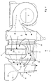
- An air mixing device 1 has two adjusting elements 2a and 2b, which are formed by means of a rotatably mounted shaft Transfer device 3 are interconnected.
- the two control elements 2a, 2b are about a common axis of rotation, which is parallel to the longitudinal direction the shaft extends, rotatably arranged in an air guide housing 4, wherein the configuration and arrangement of the adjusting elements 2a, 2a and the transfer device 3 will be described later.
- a first Air-conveying fan 5 arranged in the air guide housing 4, as seen in the air flow direction.
- This fan 5 is below an air cooling serving evaporator 6 is arranged.
- This evaporator 6 is a first air duct 6a, which is also referred to below as the cold air duct Is assigned.
- a second air channel 7a is provided, in in which a heating element serving the air heater 7 is arranged, the hereinafter also referred to as warm air duct.
- the two air channels 6a, 7a lead, separated from each other by a wall, to a mixing room 8 with a plurality of air outlets, according to the present embodiment released or closed by a distribution valve 9 as needed be, and what the tempered air over other air channels, for example a footwell and / or the windshield.
- Each of the two adjusting elements 2a, 2b has a disc-shaped form, wherein it is a stabilizing, extending in the axial direction, annular Edge with an internal toothing (not shown) and a circular segment-like Detail, which according to the embodiment of the half the bordered by the edge circular area corresponds, has.
- the internal toothing acts with a provided on the transmission device 3 external teeth together, wherein the internal toothing of the two adjusting elements 2a, 2b and the two outer gears associated therewith the transmission device 3 each formed corresponding to each other are, so that upon actuation, the two adjusting elements 2a, 2b respectively be rotated at the same angle and in the same direction. Due to the configuration of the circular segment-like section is so ensures that the total opening area is always the same, and that therefore the flow resistance and thus the total air volume during a rotation of the two adjusting elements 2a, 2b approximately remains constant.
- the two adjusting elements 2a, 2b If a rotation of the two adjusting elements 2a, 2b via an actuation the actuating device, the two adjusting elements 2a, 2b, as described above synchronously rotated by an angle and take a mixing position, as shown in Fig. 3. Due to the rotation, according to the embodiment by 90 °, change the two circular segment-like Cutouts of the two control elements 2a, 2b their position and release a part, in this case half, of the second air channel 7a, whereas a part, in the present case half, of the first air duct 6a closed becomes. Thus, as described above, a partial air flow passes through the first air channel 6a, passing the evaporator 6 directly into the mixing chamber.
- a second partial air flow passes through the second air duct 7a passing by leads to the radiator, which heats this partial air flow, which in Fig. 1 represented by arrows with a dotted line, into the mixing chamber 8, where the two partial air streams mix, which in Fig. 1 by arrows a dashed line is shown.
- the mixture can be stepless. Due to friction, for example, the shaft 10 and the shaft of Transfer device 3, there is no automatic adjustment of the air mixing device 1.
- Fig. 5 the hot position is shown, in which the two circular segment-like Cutouts of the two control elements 2a, 2b the entire air flow through the radiator 7, so that it is heated to the maximum.
Landscapes
- Physics & Mathematics (AREA)
- Thermal Sciences (AREA)
- Engineering & Computer Science (AREA)
- Mechanical Engineering (AREA)
- Air-Conditioning For Vehicles (AREA)
Abstract
Description
- Fig. 1
- einen Schnitt durch eine erfindungsgemäße Luftmischvorrichtung mit angedeutetem Strömungsverlauf,
- Fig. 2
- eine perspektivische Ansicht der Stellelemente der Luftmischvorrichtung von Fig. 1,
- Fig. 3
- eine perspektivische Ansicht der Luftmischvorrichtung von Fig. 1 in einer Mischstellung,
- Fig. 4
- eine perspektivische Ansicht der Luftmischvorrichtung von Fig. 1 in der Kaltstellung, und
- Fig. 5
- eine perspektivische Ansicht der Luftmischvorrichtung von Fig. 1 in der Warmstellung,
- 1
- Luftmischvorrichtung
- 2a
- erstes Stellelement
- 2b
- zweites Stellelement
- 3
- Übertragungsvorrichtung
- 4
- Luftführungsgehäuse
- 5
- Gebläse
- 6
- Verdampfer
- 7
- Heizkörper
- 8
- Mischraum
- 9
- Verteilerklappe
- 10
- Welle
Claims (13)
- Luftmischvorrichtung mit mindestens zwei scheibenförmigen Stellelementen (2a, 2b), dadurch gekennzeichnet, dass die scheibenförmigen Stellelemente (2a, 2b) miteinander mittels einer Übertragungsvorrichtung (3) verbunden sind.
- Luftmischvorrichtung nach Anspruch 1, dadurch gekennzeichnet, dass die Stellelemente (2a, 2b) parallel zueinander angeordnet sind.
- Luftmischvorrichtung nach Anspruch 1 oder 2, dadurch gekennzeichnet, dass die Stellelemente (2a, 2b) Drehachsen aufweisen, die zusammenfallen.
- Luftmischvorrichtung nach einem der vorhergehenden Ansprüche, dadurch gekennzeichnet, dass die Stellelemente (2a, 2b) einen kreissegmentartigen Ausschnitt aufweisen.
- Luftmischvorrichtung nach einem der vorhergehenden Ansprüche, dadurch gekennzeichnet, dass die Übertragungsvorrichtung (3) durch eine Welle gebildet ist.
- Luftmischvorrichtung nach einem der vorhergehenden Ansprüche, dadurch gekennzeichnet, dass die Übertragungsvorrichtung (3) durch eine Welle gebildet ist, die parallel zu mindestens einer Drehachse eines Stellelements (2a, 2b) angeordnet ist.
- Luftmischvorrichtung nach einem der vorhergehenden Ansprüche, dadurch gekennzeichnet, dass die Übertragungsvorrichtung (3) exzentrisch bezüglich mindestens einem der Stellelemente (2a, 2b) angeordnet ist.
- Luftmischvorrichtung nach einem der vorhergehenden Ansprüche, dadurch gekennzeichnet, dass die Übertragungsvorrichtung (3) parallel zur Drehachse beider Stellelemente (2a, 2b) angeordnet ist.
- Luftmischvorrichtung nach einem der vorhergehenden Ansprüche, dadurch gekennzeichnet, dass die Luftmischvorrichtung (1) eine Verteilerklappe (9) aufweist.
- Luftmischvorrichtung nach Anspruch 9, dadurch gekennzeichnet, dass die Verteilerklappe (9) um eine Drehachse drehbar ist, die mit der Drehachse mindestens eines der Stellelemente (2a, 2b) zusammenfällt.
- Luftmischvorrichtung nach einem der vorhergehenden Ansprüche, dadurch gekennzeichnet, dass ein gemeinsamer Antrieb für die Stellelemente (2a, 2b) vorgesehen ist.
- Luftmischvorrichtung nach einem der vorhergehenden Ansprüche, dadurch gekennzeichnet, dass die Stellelemente (2a, 2b) ausschließlich gleichzeitig betätigbar sind.
- Luftmischvorrichtung nach Anspruch 12, dadurch gekennzeichnet, dass in den einzelnen Stellungen der Stellelemente (2a, 2b) jedes Stellelement (2a, 2b) in der gleichen Stellung bezüglich einem zu verschließenden oder freizugebenden Luftkanal (6a, 7a) angeordnet ist.
Applications Claiming Priority (2)
| Application Number | Priority Date | Filing Date | Title |
|---|---|---|---|
| DE10320577 | 2003-05-07 | ||
| DE2003120577 DE10320577A1 (de) | 2003-05-07 | 2003-05-07 | Luftmischvorrichtung für eine Klimaanlage |
Publications (2)
| Publication Number | Publication Date |
|---|---|
| EP1475258A1 true EP1475258A1 (de) | 2004-11-10 |
| EP1475258B1 EP1475258B1 (de) | 2006-08-30 |
Family
ID=32981281
Family Applications (1)
| Application Number | Title | Priority Date | Filing Date |
|---|---|---|---|
| EP20040010754 Expired - Lifetime EP1475258B1 (de) | 2003-05-07 | 2004-05-06 | Luftmischvorrichtung für eine Klimaanlage |
Country Status (3)
| Country | Link |
|---|---|
| EP (1) | EP1475258B1 (de) |
| DE (2) | DE10320577A1 (de) |
| ES (1) | ES2270217T3 (de) |
Citations (4)
| Publication number | Priority date | Publication date | Assignee | Title |
|---|---|---|---|---|
| US5025711A (en) * | 1990-05-23 | 1991-06-25 | General Motors Corporation | Simultaneous temperature and mode selector for heating and cooling |
| EP0560774B1 (de) * | 1990-09-17 | 1995-11-22 | Saab Automobile Aktiebolag | Verteiler für fahrzeugbelüftungssystem |
| EP0709241A1 (de) * | 1994-10-28 | 1996-05-01 | Valeo Climatisation | Heizungs- und/oder Belüftungsanlage eines Fahrzeuginnenraumes |
| EP1038704A1 (de) * | 1999-03-23 | 2000-09-27 | Ecia Industrie | Luftsteuervorrichtung und Fahrzeug-Klimaanlage enthaltend dieselbe |
Family Cites Families (1)
| Publication number | Priority date | Publication date | Assignee | Title |
|---|---|---|---|---|
| US5399120A (en) * | 1993-11-05 | 1995-03-21 | General Motors Corporation | Air conditioning system control valve |
-
2003
- 2003-05-07 DE DE2003120577 patent/DE10320577A1/de not_active Withdrawn
-
2004
- 2004-05-06 DE DE200450001305 patent/DE502004001305D1/de not_active Expired - Lifetime
- 2004-05-06 ES ES04010754T patent/ES2270217T3/es not_active Expired - Lifetime
- 2004-05-06 EP EP20040010754 patent/EP1475258B1/de not_active Expired - Lifetime
Patent Citations (4)
| Publication number | Priority date | Publication date | Assignee | Title |
|---|---|---|---|---|
| US5025711A (en) * | 1990-05-23 | 1991-06-25 | General Motors Corporation | Simultaneous temperature and mode selector for heating and cooling |
| EP0560774B1 (de) * | 1990-09-17 | 1995-11-22 | Saab Automobile Aktiebolag | Verteiler für fahrzeugbelüftungssystem |
| EP0709241A1 (de) * | 1994-10-28 | 1996-05-01 | Valeo Climatisation | Heizungs- und/oder Belüftungsanlage eines Fahrzeuginnenraumes |
| EP1038704A1 (de) * | 1999-03-23 | 2000-09-27 | Ecia Industrie | Luftsteuervorrichtung und Fahrzeug-Klimaanlage enthaltend dieselbe |
Also Published As
| Publication number | Publication date |
|---|---|
| DE10320577A1 (de) | 2004-11-25 |
| DE502004001305D1 (de) | 2006-10-12 |
| ES2270217T3 (es) | 2007-04-01 |
| EP1475258B1 (de) | 2006-08-30 |
Similar Documents
| Publication | Publication Date | Title |
|---|---|---|
| DE102011002606B4 (de) | Belüftungssteuervorrichtung für eine Heizungs- und/oder Klimaanlage eines Fahrzeugs | |
| DE102015112378B4 (de) | System zur Luftverteilung einer Klimaanlage eines Kraftfahrzeugs und Verfahren zum Betreiben des Systems | |
| DE102004054570A1 (de) | Fahrzeug-Klimasystem mit einem Klappenantriebsmechanismus | |
| EP1520738B1 (de) | Lamellendüse, insbesondere für eine Klimaanlage eines Kraftfahrzeugs | |
| DE102015110481A1 (de) | Vorrichtung zum Beheizen, Belüften und/oder Klimatisieren eines Fahrzeuginnenraums | |
| DE102005036159B4 (de) | Luftstromsteuereinheit | |
| DE102014203850A1 (de) | Klimatisierungsvorrichtung für ein Kraftfahrzeug und Steuerungsverfahren dafür | |
| EP1306241B2 (de) | Fahrzeugheiz- und Klimaanlage mit kombinierter Luftmisch- und -verteilklappe | |
| EP2030816B1 (de) | Klimaanlage für ein Kraftfahrzeug mit einer Fondraumklappe zum Mischen und Verteilen der Luft | |
| EP1911616A1 (de) | Luftdüse zur Belüftung eines Fahrzeuginnenraums | |
| DE102004002363A1 (de) | Stellvorrichtung und Heizungs- oder Klimatisierungseinrichtung | |
| EP1930191A1 (de) | Fahrzeugheizungs- und/oder Klimaanlage mit kombinierter Luftmisch- und -verteilerklappe | |
| EP1475258B1 (de) | Luftmischvorrichtung für eine Klimaanlage | |
| DE102021122951A1 (de) | Integrierte Klappenanordnung für ein Heizungs-, Lüftungs- und Klimatisierungssystem (HLK-System) eines Kraftfahrzeugs | |
| DE102017114119A1 (de) | Klimatisierungseinrichtung für ein Fahrzeug | |
| DE102014106307A1 (de) | Ventilklappenbaugruppe | |
| EP2390123B1 (de) | Anlage zur Steuerung wenigstens zweier Luftströme | |
| EP1522434B1 (de) | Klimaanlage, insbesondere Kraftfahrzeug-Klimaanlage | |
| DE69613758T2 (de) | Rollende Arretiervorrichtung | |
| EP1520736A2 (de) | Getriebeanordnung für eine Luftregelungsvorrichtung, insbesondere für eine Klimaanlage eines Kraftfahrzeugs | |
| EP1531067B1 (de) | Klimatisierungsvorrichtung, insbesondere für ein Kraftfahrzeug | |
| EP1522435B1 (de) | Vorrichtung zum Verschliessen und Freigeben von Luftdurchtritts-Öffnungen und Klimaanlage mit einer derartigen Vorrichtung | |
| EP1555148B1 (de) | Klimatisierungsvorrichtung, insbesondere für ein Kraftfahrzeug | |
| EP1348582B1 (de) | Heizungs- oder Klimaanlage für ein Kraftfahrzeug | |
| EP0457935B2 (de) | Betätigungsvorrichtung für Bowdenzüge |
Legal Events
| Date | Code | Title | Description |
|---|---|---|---|
| PUAI | Public reference made under article 153(3) epc to a published international application that has entered the european phase |
Free format text: ORIGINAL CODE: 0009012 |
|
| AK | Designated contracting states |
Kind code of ref document: A1 Designated state(s): AT BE BG CH CY CZ DE DK EE ES FI FR GB GR HU IE IT LI LU MC NL PL PT RO SE SI SK TR |
|
| AX | Request for extension of the european patent |
Extension state: AL HR LT LV MK |
|
| 17P | Request for examination filed |
Effective date: 20050510 |
|
| AKX | Designation fees paid |
Designated state(s): DE ES FR IT |
|
| 17Q | First examination report despatched |
Effective date: 20050704 |
|
| GRAP | Despatch of communication of intention to grant a patent |
Free format text: ORIGINAL CODE: EPIDOSNIGR1 |
|
| GRAS | Grant fee paid |
Free format text: ORIGINAL CODE: EPIDOSNIGR3 |
|
| GRAA | (expected) grant |
Free format text: ORIGINAL CODE: 0009210 |
|
| AK | Designated contracting states |
Kind code of ref document: B1 Designated state(s): DE ES FR IT |
|
| PG25 | Lapsed in a contracting state [announced via postgrant information from national office to epo] |
Ref country code: IT Free format text: LAPSE BECAUSE OF FAILURE TO SUBMIT A TRANSLATION OF THE DESCRIPTION OR TO PAY THE FEE WITHIN THE PRESCRIBED TIME-LIMIT;WARNING: LAPSES OF ITALIAN PATENTS WITH EFFECTIVE DATE BEFORE 2007 MAY HAVE OCCURRED AT ANY TIME BEFORE 2007. THE CORRECT EFFECTIVE DATE MAY BE DIFFERENT FROM THE ONE RECORDED. Effective date: 20060830 |
|
| REF | Corresponds to: |
Ref document number: 502004001305 Country of ref document: DE Date of ref document: 20061012 Kind code of ref document: P |
|
| ET | Fr: translation filed | ||
| REG | Reference to a national code |
Ref country code: ES Ref legal event code: FG2A Ref document number: 2270217 Country of ref document: ES Kind code of ref document: T3 |
|
| PLBE | No opposition filed within time limit |
Free format text: ORIGINAL CODE: 0009261 |
|
| STAA | Information on the status of an ep patent application or granted ep patent |
Free format text: STATUS: NO OPPOSITION FILED WITHIN TIME LIMIT |
|
| 26N | No opposition filed |
Effective date: 20070531 |
|
| PGFP | Annual fee paid to national office [announced via postgrant information from national office to epo] |
Ref country code: ES Payment date: 20080522 Year of fee payment: 5 |
|
| PGFP | Annual fee paid to national office [announced via postgrant information from national office to epo] |
Ref country code: IT Payment date: 20080520 Year of fee payment: 5 |
|
| PGRI | Patent reinstated in contracting state [announced from national office to epo] |
Ref country code: IT Effective date: 20080601 |
|
| REG | Reference to a national code |
Ref country code: ES Ref legal event code: FD2A Effective date: 20090507 |
|
| PG25 | Lapsed in a contracting state [announced via postgrant information from national office to epo] |
Ref country code: ES Free format text: LAPSE BECAUSE OF NON-PAYMENT OF DUE FEES Effective date: 20090507 |
|
| PG25 | Lapsed in a contracting state [announced via postgrant information from national office to epo] |
Ref country code: IT Free format text: LAPSE BECAUSE OF NON-PAYMENT OF DUE FEES Effective date: 20090506 |
|
| PGFP | Annual fee paid to national office [announced via postgrant information from national office to epo] |
Ref country code: DE Payment date: 20120625 Year of fee payment: 9 |
|
| PGFP | Annual fee paid to national office [announced via postgrant information from national office to epo] |
Ref country code: FR Payment date: 20120614 Year of fee payment: 9 |
|
| PG25 | Lapsed in a contracting state [announced via postgrant information from national office to epo] |
Ref country code: DE Free format text: LAPSE BECAUSE OF NON-PAYMENT OF DUE FEES Effective date: 20131203 |
|
| REG | Reference to a national code |
Ref country code: FR Ref legal event code: ST Effective date: 20140131 |
|
| REG | Reference to a national code |
Ref country code: DE Ref legal event code: R119 Ref document number: 502004001305 Country of ref document: DE Effective date: 20131203 |
|
| PG25 | Lapsed in a contracting state [announced via postgrant information from national office to epo] |
Ref country code: FR Free format text: LAPSE BECAUSE OF NON-PAYMENT OF DUE FEES Effective date: 20130531 |