EP1475245A2 - Bicycle rim - Google Patents
Bicycle rim Download PDFInfo
- Publication number
- EP1475245A2 EP1475245A2 EP04010833A EP04010833A EP1475245A2 EP 1475245 A2 EP1475245 A2 EP 1475245A2 EP 04010833 A EP04010833 A EP 04010833A EP 04010833 A EP04010833 A EP 04010833A EP 1475245 A2 EP1475245 A2 EP 1475245A2
- Authority
- EP
- European Patent Office
- Prior art keywords
- rim
- attachment portion
- reinforcement members
- annular
- spoke
- Prior art date
- Legal status (The legal status is an assumption and is not a legal conclusion. Google has not performed a legal analysis and makes no representation as to the accuracy of the status listed.)
- Granted
Links
Images


Classifications
-
- B—PERFORMING OPERATIONS; TRANSPORTING
- B60—VEHICLES IN GENERAL
- B60B—VEHICLE WHEELS; CASTORS; AXLES FOR WHEELS OR CASTORS; INCREASING WHEEL ADHESION
- B60B1/00—Spoked wheels; Spokes thereof
- B60B1/02—Wheels with wire or other tension spokes
- B60B1/0261—Wheels with wire or other tension spokes characterised by spoke form
- B60B1/0284—Wheels with wire or other tension spokes characterised by spoke form the spoke being threaded at both ends
-
- B—PERFORMING OPERATIONS; TRANSPORTING
- B60—VEHICLES IN GENERAL
- B60B—VEHICLE WHEELS; CASTORS; AXLES FOR WHEELS OR CASTORS; INCREASING WHEEL ADHESION
- B60B1/00—Spoked wheels; Spokes thereof
- B60B1/02—Wheels with wire or other tension spokes
- B60B1/04—Attaching spokes to rim or hub
- B60B1/041—Attaching spokes to rim or hub of bicycle wheels
-
- B—PERFORMING OPERATIONS; TRANSPORTING
- B60—VEHICLES IN GENERAL
- B60B—VEHICLE WHEELS; CASTORS; AXLES FOR WHEELS OR CASTORS; INCREASING WHEEL ADHESION
- B60B1/00—Spoked wheels; Spokes thereof
- B60B1/02—Wheels with wire or other tension spokes
- B60B1/04—Attaching spokes to rim or hub
- B60B1/042—Attaching spokes to hub
-
- B—PERFORMING OPERATIONS; TRANSPORTING
- B60—VEHICLES IN GENERAL
- B60B—VEHICLE WHEELS; CASTORS; AXLES FOR WHEELS OR CASTORS; INCREASING WHEEL ADHESION
- B60B1/00—Spoked wheels; Spokes thereof
- B60B1/02—Wheels with wire or other tension spokes
- B60B1/04—Attaching spokes to rim or hub
- B60B1/043—Attaching spokes to rim
- B60B1/048—Attaching spokes to rim by the use of screws
-
- B—PERFORMING OPERATIONS; TRANSPORTING
- B60—VEHICLES IN GENERAL
- B60B—VEHICLE WHEELS; CASTORS; AXLES FOR WHEELS OR CASTORS; INCREASING WHEEL ADHESION
- B60B21/00—Rims
- B60B21/02—Rims characterised by transverse section
- B60B21/025—Rims characterised by transverse section the transverse section being hollow
-
- B—PERFORMING OPERATIONS; TRANSPORTING
- B60—VEHICLES IN GENERAL
- B60B—VEHICLE WHEELS; CASTORS; AXLES FOR WHEELS OR CASTORS; INCREASING WHEEL ADHESION
- B60B21/00—Rims
- B60B21/02—Rims characterised by transverse section
- B60B21/04—Rims characterised by transverse section with substantially radial flanges
-
- B—PERFORMING OPERATIONS; TRANSPORTING
- B60—VEHICLES IN GENERAL
- B60B—VEHICLE WHEELS; CASTORS; AXLES FOR WHEELS OR CASTORS; INCREASING WHEEL ADHESION
- B60B21/00—Rims
- B60B21/06—Rims characterised by means for attaching spokes, i.e. spoke seats
- B60B21/062—Rims characterised by means for attaching spokes, i.e. spoke seats for bicycles
-
- B—PERFORMING OPERATIONS; TRANSPORTING
- B60—VEHICLES IN GENERAL
- B60B—VEHICLE WHEELS; CASTORS; AXLES FOR WHEELS OR CASTORS; INCREASING WHEEL ADHESION
- B60B21/00—Rims
- B60B21/12—Appurtenances, e.g. lining bands
-
- B—PERFORMING OPERATIONS; TRANSPORTING
- B60—VEHICLES IN GENERAL
- B60B—VEHICLE WHEELS; CASTORS; AXLES FOR WHEELS OR CASTORS; INCREASING WHEEL ADHESION
- B60B27/00—Hubs
- B60B27/0005—Hubs with ball bearings
-
- B—PERFORMING OPERATIONS; TRANSPORTING
- B60—VEHICLES IN GENERAL
- B60B—VEHICLE WHEELS; CASTORS; AXLES FOR WHEELS OR CASTORS; INCREASING WHEEL ADHESION
- B60B27/00—Hubs
- B60B27/02—Hubs adapted to be rotatably arranged on axle
- B60B27/023—Hubs adapted to be rotatably arranged on axle specially adapted for bicycles
- B60B27/026—Hubs adapted to be rotatably arranged on axle specially adapted for bicycles comprising quick release devices
Definitions
- This invention generally relates to a bicycle wheel. More specifically, the present invention relates to a bicycle wheel having a reinforced rim.
- Bicycling is becoming an increasingly more popular form of recreation as well as a means of transportation. Moreover, bicycling has become a very popular competitive sport for both amateurs and professionals. Whether the bicycle is used for recreation, transportation or competition, the bicycle industry is constantly improving the various components of the bicycle as well as the frame of the bicycle. One component that has been extensively redesigned is the bicycle wheel. Bicycle wheels are constantly being redesigned to be strong, lightweight and more aerodynamic in design as well as to be simple to manufacture and assemble.
- bicycle wheels There are many different types of bicycle wheels, which are currently available on the market.
- Most bicycle wheels have a hub portion, a plurality of spokes and an annular rim.
- the hub portion is attached to a part of the frame of the bicycle for relative rotation.
- the inner ends of the spokes are coupled to the hub and extend outwardly from the hub.
- the annular rim is coupled to the outer ends of the spokes and has an outer portion for supporting a pneumatic tire thereon.
- the spokes of the bicycle wheel are thin metal wire spokes.
- the ends of the hub are usually provided with flanges that are used to couple the spokes to the hub. In particular, holes are provided in the hub flanges.
- the wire spokes are usually bent on their inner end and provided with a flange that is formed in the shape of a nail head.
- the inner end is supported in one of the holes in one of the hub flanges.
- the outer ends of the spokes typically are provided with threads for engaging spoke nipples, which secure the outer ends of the wire spokes to holes in the rim.
- tubeless tire wheels have an annular seal arranged to seal the spoke attachment openings of the rim.
- Rims designed for tube tires also often have an annular member covering the spoke attachments.
- these typical types of wheels can be expensive and complicated to manufacture and assemble.
- these typical wheels are not always as strong and lightweight, as desired.
- it can be difficult, complicated and/or expensive to replace a spoke or spokes.
- One object of the present invention is to provide a bicycle wheel with a rim that is relatively strong yet relatively lightweight.
- Another object of the present invention is to provide a rim that is relatively simple and inexpensive to manufacture and assemble.
- a bicycle rim that includes an annular tire attachment portion, an annular spoke attachment portion and a plurality of reinforcement members.
- the annular tire attachment portion is adapted to have a tires mounted thereon.
- the annular spoke attachment portion is fixedly coupled with the tire attachment portion.
- the spoke attachment portion includes a plurality of circumferentially spaced attachment openings with each opening having a central axis extending therethrough.
- the reinforcement members are fixedly coupled to the spoke attachment portion at the attachment openings to effectively increase the thickness of the spoke attachment portion of the rim at the attachment openings.
- Each of the reinforcement members is bonded to the spoke attachment portion.
- Each reinforcement member has a base section including a rim facing surface, an exterior facing surface and a through opening. The rim facing surfaces contact an outer surface of the spoke attachment portion of the rim. The exterior facing surfaces face in an opposite direction from the rim facing surfaces.
- the through openings are aligned with the attachment openings.
- Figure 1 is a side elevational view of a bicycle wheel with a reinforced rim in accordance with a first preferred embodiment of the present invention
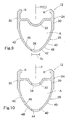
- Figure 2 is a side elevational view of the reinforced rim of the wheel illustrated in Figure 1;
- Figure 3 is an enlarged, axial cross-sectional view of the area of the reinforced rim .identified by circle 3 in Figure 2 (i.e., across-sectional view as seen along the center plane of the wheel);
- Figure 4 is an enlarged, partial cross-sectional view of the reinforced rim illustrated in Figures 1-2, as viewed along section line 4-4 of . Figure 2;
- Figure 5 is an enlarged, axial cross-sectional view of the area of the reinforced rim identified by circle 5 in Figure 2 (i.e., across-sectional view as seen along the center plane of the wheel);
- Figure 6 is an enlarged, partial cross-sectional view of the reinforced rim illustrated in Figures 1-2, as viewed along section line 6-6 of Figure 2;
- Figure 7 is an enlarged, axial cross-sectional view of the area of the reinforced rim identified by circle 3 in Figure 2 (i.e., across-sectional view as seen along the center plane of the wheel), with the cross-hatching removed for the purpose of illustration;
- Figure 8 is an enlarged, partial cross-sectional view of the bicycle wheel illustrated in Figure 1, as seen along section line 8-8 of Figure 1;
- Figure 9 is an enlarged, partial cross-sectional view of the bicycle wheel illustrated in Figure 1, as seen along section line 8-8 of Figure 1, with the tire, spokes and reinforcement members removed for the purpose of illustration;
- Figure 10 is an enlarged, partial cross-sectional view of the bicycle wheel illustrated in Figures 1 and 8, as seen along section line 10-10 of Figure 1, with the tire removed for the purpose of illustration;
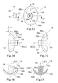
- Figure 11 is an enlarged inside elevational view (i.e. inner radial view) of a pre-formed reinforcement member prior to deforming the reinforcement member into the final desired shape to be mounted to the inner annular portion of the reinforced rim;
- Figure 12 is an enlarged inside elevational view (i.e. inner radial view) of one of the reinforcement members of the bicycle rim illustrated in Figures 1-8, after deforming the pre-formed reinforcement member illustrated in Figure 11 into the final desired shape, with the pre-formed shape shown in phantom broken lines;
- Figure 13 is an outside elevational view (i.e. outer radial view) of the reinforcement member illustrated in Figure 12;
- Figure 14 is a side (axial) elevational view of the reinforcement member illustrated in Figures 12 and 13;
- Figure 15 is an opposite side (axial) elevational view of the reinforcement member illustrated in Figures 12-14;
- Figure 16 is an end (circumferential) elevational view of the reinforcement member illustrated in Figures 12-15, as viewed along arrow 16 of Figure 13;
- Figure 17 is a cross-sectional view of the reinforcement member illustrated in Figures 12-16, as see along section line 17-17 of Figure 13;
- Figure 18 is an enlarged, top plan view of the hub of the bicycle wheel illustrated in Figure 1 with portions shown in cross-section for the purpose of illustration;
- Figure 19 is an enlarged, top plan view of the hub body of the hub illustrated in Figure 18;
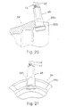
- Figure 20 is a partial, enlarged cross-sectional view of a portion of the hub body illustrated in Figures 18 and 19 with a spoke nipple arranged in a spoke hole;
- Figure 21 is a right side elevational view of the portion of the hub body and spoke nipple illustrated in Figure 20;
- Figure 22 is a side elevational view of a bicycle wheel with a reinforced rim in accordance with a second preferred embodiment of the present invention.
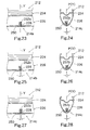
- Figure 23 is an enlarged, axial cross-sectional view of the area of the rim identified by circle 23 in Figure 22 (i.e., a cross-sectional view as seen along the center plane of the wheel);
- Figure 24 is an enlarged, partial cross-sectional view of the wheel illustrated in Figure 22, as viewed along section line 24-24 of Figure 22;
- Figure 25 is an enlarged, axial cross-sectional view of the area of the rim identified by circle 25 in Figure 22 (i.e., a cross-sectional view as seen along the center plane of the wheel);
- Figure 26 is an enlarged, partial cross-sectional view of the wheel illustrated in Figure 22, as viewed along section line 26-26 of Figure 22;
- Figure 27 is an enlarged, axial cross-sectional view of the area of the wheel identified by circle 27 in Figure 22 (i.e., a cross-sectional view as seen along the center plane of the wheel);
- Figure 28 is an enlarged, partial cross-sectional view of the rim illustrated in Figure 22, as viewed along section line 28-28 of Figure 22.
- a bicycle wheel 10 is illustrated in accordance with a first preferred embodiment of the present invention.
- the bicycle wheel 10 utilizes a reinforced rim 12 that has a plurality of reinforcement members 14 fixedly coupled thereto in accordance with the present invention.
- the reinforcement members 14 When the reinforcement members 14 are fixedly coupled to the rim 12, the reinforcement members 14 form part of the rim 12.
- the bicycle wheel 10 basically includes the rim 12 with the reinforcement members 14, a plurality of spokes 16, a pneumatic tire 18 and a center hub 20.
- the tire 18 can include a tube (not shown) and a separate tire, or can be a tubeless type tire, as discussed below in more detail.
- the spokes 16 are radial spokes that connect the hub 20 to the rim 12.
- the hub 20 is a front hub (i.e. the hub 20 does not include one or more sprockets) that utilizes sixteen radial spokes 16 coupled to the rim 12 at equally spaced circumferential locations as seen in Figure 1.
- bicycle wheel 10 could use a modified rim and/or hub in order to accommodate different spoking arrangements (e.g. all tangential spokes, some tangential spokes and some radial spokes, etc.) without departing from the scope of the present invention.
- bicycle wheel 10 could use a modified rim and/or hub in order to accommodate one or more sprockets, as needed and/or desired.
- bicycle wheel 10 could use a modified rim and/or hub in order to accommodate fewer or more spokes 16 if needed and/or desired.
- the spokes 16 are preferably coupled to the annular rim 12 in circumferentially spaced arrangement via the reinforcement members 14.
- the rim 12 is an annular member designed for rotation about a center axis X.
- the rim 12 is constructed of a substantially rigid material, such as those materials, which are well known in the art.
- the rim 12 can be constructed of any suitable metallic material, such as plated steel, stainless steel, aluminum, magnesium or titanium, as well as other non-metallic materials, such as a carbon fiber composite.
- the rim 12 is constructed of aluminum. The construction of the rim 12 will be discussed in more detail below.
- the rim 12 is substantially circular as seen in side elevation ( Figures 1 and 2), and basically includes an outer annular portion 24, an inner annular portion 26 with a plurality of attachment openings 28, and the plurality of the reinforcement members 14 fixedly coupled to the inner annular portion 26 at the attachment openings 28 to reinforce the rim 12.
- the outer annular portion 24 is a tire attachment portion
- the inner annular portion 26 is a spoke attachment portion.
- the rim 12 has a uniform cross-sectional profile as seen in. Figures 4, 6, and 8-10, except for the absence of material at various openings formed in the rim 12 as described herein.
- the inner annular portion 26 is fixedly coupled with the outer annular portion 24 to form an annular hollow area A, as best seen in Figures 8-10.
- the inner annular portion 26 preferably has a U-shaped cross-section with the ends of the U-shaped inner annular portion 26 coupled to opposite axial sides of the outer annular portion 24 to form the annular hollow area A.
- the outer annular portion 24 also preferably has a substantially U-shaped cross-section with the free ends of the substantially U-shaped outer annular portion designed to retain the tire 18.
- the outer annular portion 24 and the inner annular portion 26 are preferably integrally formed together as a one-piece unitary aluminum member to form a constant cross-sectional shape about the entire circumference of the outer and inner annular portions 24 and 26 of the rim 12 in a relatively conventional manner.
- the outer and inner annular portions 24 and 26 can be constructed by extruding a length of aluminum with the cross-sectional shape illustrated in Figures 8-10, then bending the length of aluminum into a circular shape, and then fixing (i.e., welding) the ends of the length of aluminum together.
- the attachment openings 28 can be punched or drilled in a conventional manner before or after welding the free ends of the length of aluminum together.
- the reinforcement members 14 are preferably formed as separate aluminum members from the outer and inner annular portions 24 and 26 by casting, machining and/or any other suitable manufacturing technique to result in the initial shape illustrated in Figure 10, and then by bending (i.e., deforming) them to the desired final shape illustrated in the remaining Figures.
- the reinforcement members 14 could be initially formed into the final shape by casting, machining and/or any other suitable manufacturing technique.
- the reinforcement members 14 are then fixedly coupled to the inner annular portion 26 of the rim 12.
- the reinforcement members 14 are bonded to the inner annular portion 26 by brazing or soldering in order to reinforce the rim 12, as discussed below in more detail.
- the outer and inner annular portions 24 and 26 each have a symmetrical cross-sectional shape relative to a center plane P that is perpendicular to the center axis X of the wheel 10.
- the rim 12 is not completely (i.e. not exactly or perfectly) symmetrical relative to the center plane P due to the arrangements of the reinforcement members 14, as discussed below in more detail.
- the rim 12 preferably has a substantially symmetrical shape relative to the center plane P of the wheel 10 when the reinforcement members 14 are coupled thereto. In other words, prior to fixedly coupling the reinforcement members 14 to the inner annular portion 26, the rim 12 is symmetrical.
- the outer annular portion 24 basically includes a pair of annular side sections or tire support sections 30 and an annular outer bridge or connecting section 32.
- the annular connecting section 32 extends between the annular side sections 30 to form a substantially U-shaped tire receiving recess as seen in cross-section as best seen in Figures 4, 6 and 8-10.
- the annular side sections 30 are annular plate shaped members that are preferably between about 1.1 and about 1.4 millimeters thick that form a pair of annular tire supporting surfaces and a pair of annular braking surfaces in a conventional manner.
- the tire supporting surfaces of the annular side sections 30 are annular opposed planar annular surfaces that face each other toward the center plane P.
- the tire supporting surfaces have annular ribs R formed at their free ends to retain beads of the tire 18 in a conventional manner.
- the annular ribs R project axially toward each other.
- the annular braking surfaces of the annular side sections 30 are annular opposed planar annular surfaces that face outwardly away from the center plane P to engage conventional rim brakes.
- the radially inner ends of the annular side sections 30 are fixedly coupled to the inner annular portion 26.
- the annular connecting section 32 is a tubular member that has a substantially constant thickness of about 0.9 millimeters.
- the annular connecting section 32 preferably has a varying, contoured shape, as best shown in Figures 8-10 to assist in mounting a tubeless tire thereto.
- the annular connecting section 32 preferably includes a single valve aperture 34 formed therein for coupling a valve 36 therein in a conventional manner, as seen in Figures 1 and 10.
- the annular connecting section 32 is fixedly coupled to the annular side sections 30 at radial positions between the inner and outer ends of the annular side sections 30.
- the connecting section 32 is free of openings, except for the single valve aperture 34 such that the tire 18 can be a tubeless tire.
- the tire 18 could be a tube-type tire (not shown), and that the valve aperture 34 could receive the valve of a tube (not shown) in a conventional manner.
- the valve aperture 34 and/or the valve 36 can be designed for a tubeless tire in a conventional manner, and/or for a tube-type tire in a conventional manner.
- the valve 36 is conventional, the valve 36 will not be discussed and/or illustrated in detail herein.
- the inner annular portion 26 is a curved tubular member that has a U-shaped or V-shaped cross-sectional shape.
- the inner annular portion 26 preferably has a constant thickness of about 0.8 millimeters.
- the inner annular portion 26 basically includes a pair of annular slanted sections 40 and an inner annular section 42 fixedly coupled to the slanted sections 40.
- the annular slanted sections 40 and the inner annular section 42 of the inner annular portion 26, and the annular side sections 30 and annular connecting section 32 of the outer annular portion 24 are preferably integrally formed together as a one-piece, unitary member that is separate from the reinforcement members 14.
- the plurality of attachment openings 28 are formed in the inner annular section 42 and are designed to have the spokes 16 mounted therein via the reinforcement members 14.
- Outer radial ends of the slanted sections 40 are fixedly coupled to inner radial ends of the annular side sections 30 of the outer annular portion 24.
- Inner radial ends of the slanted sections 40 are fixedly coupled to outer radial ends of the inner annular section 42.
- the attachment openings 28 of the inner annular section 42 are preferably identical, circular-shaped openings with their central axes C extending in the radial direction along the center plane P.
- the inner annular section 42 preferably has sixteen (16) of the attachment openings 28 arranged in a circumferentially equally spaced manner from each other about the entire circumference of the rim 12.
- the inner annular section 42 preferably includes a single valve opening 44 formed therein for coupling the valve 36 thereto in a conventional manner, as seen in Figures 1 and 10.
- the valve 36 is preferably designed such that the tire 18 can be a tubeless tire, as mentioned above. However, it will be apparent to those skilled in the art from this disclosure that the tire 18 could be a tube-type tire (not shown), and that the valve opening 44 could receive the valve of a tube (not shown) in a conventional manner.
- the valve opening 44 and/or the valve 36 can be designed for a tubeless tire in a conventional manner, and/or for a tube-type tire in a conventional manner.
- the inner annular section 42 together with the annular slanted sections 40 define annular curved interior and exterior surfaces 46 and 48 of the inner annular portion 26.
- the reinforcement members 14 are preferably fixedly coupled to the exterior surface 48 by brazing or soldering such that the reinforcement members 14 are bonded to the exterior surface 48 of the inner annular portion 26.
- the attachment openings 28 extend between the interior and exterior surfaces 46 and 48 of the inner annular portion 26.
- the attachment openings 28 are preferably identical to each other.
- the attachment openings 28 are arranged and configured (i.e., sufficiently wide) so that the reinforcement members 14 can be arranged therein in an alternating angled arrangement such that the spokes 16 extend to opposite ends of the hub 20.
- each reinforcement member 14 is preferably constructed as a one-piece unitary member from a lightweight, rigid metallic material. Specifically, each reinforcement member 14 is preferably constructed of aluminum, as mentioned above. In any case, the reinforcement members 14 are preferably constructed of the same material as the outer and inner annular portions 24 and 26, and are permanently bonded (e.g., by brazing or soldering) to the inner annular portion 26 to reinforce the rim 12. The reinforcement members 14 effectively increase the thickness of the inner annular portion 26 at the attachment openings 28 to provide rigid reinforcement to the rim 12.
- the reinforcement members 14 are bonded to the inner annular portion 26, preferably utilizing a brazing or soldering metal (not shown) as the bonding agent.
- a brazing or soldering metal such as those well known in the bicycle art, is used that is different than the material of the reinforcement members 14 and the inner annular portion 26.
- the brazing or soldering material is a metallic material with a lower melting point than the material of the reinforcement members 14 and the inner annular portion 26.
- a brazing/soldering metal with a melting point of about 300° Celsius is preferable for attaching the reinforcement members 14. This temperature is a lower temperature than that typically required for welding, when two rigid metals are fused together.
- brazing or soldering with a metal brazing/soldering bonding material is a preferable attachment method for the rim 12 of the present invention, it will be apparent to those skilled in the art from this disclosure that other bonding techniques can be utilized as needed and/or desired.
- the reinforcement members 14 could be bonded to the inner annular portion 26 with adhesive or a cementing agent (e.g., other than metal), instead of a brazing/soldering metal.
- each of the reinforcement members 14 has a substantially inverted mushroom shape as best shown in Figures 12-17. All of the reinforcement members 14 are preferably identical to each other. Thus, only one of the reinforcement members 14 will be discussed and/or illustrated in detail herein. However, the reinforcement members 14 are preferably mounted in an alternating orientation in alternating attachment openings 28 such that the spokes 16 extend to the appropriate ends of the hub 20, as best seen in Figures 1, 2, 3 and 5. As mentioned above, the reinforcement members 14 a pre-formed into the shape illustrated in Figure 11 with a flat base and a tubular section perpendicular to the flat base. The pre-formed shape is then deformed into the desired final shape with a curved base section and an angled tubular section, as explained herein.
- each reinforcement member 14 basically includes a base section 50, a tubular section 52 extending from the base section 50 and a through opening 54 extending through both the base section 50 and the tubular section 52, as best seen in Figures 12-17.
- One end of one of the spokes 16 is coupled within the through opening 54 to couple the rim 12 to the hub 20.
- the through opening 54 is preferably an internally threaded opening in order to threadedly couple one of the spokes 16 thereto.
- one of the spokes 16 can be adjustably, releasably coupled to the rim 12 via each reinforcement member 14.
- the base section 50 is an elongated plate that preferably has a rim facing surface 56a and an exterior facing surface 56b.
- the base section 50 is curved as viewed in radial cross-section, as best seen in Figures 16 and 17.
- the base section 50 preferably has a symmetrical shape as viewed in the radial direction relative to a center longitudinal plane L and relative to a center transverse plane W, as best seen in Figures 12-17.
- the base section 50 is substantially oval-shaped.
- the rim facing surface 56a is a contoured surface that corresponds to the contour of the exterior surface 48 of the inner annular portion 26.
- the exterior facing surface 56b has a contour substantially the same as the rim facing surface 56a, except that the exterior facing surface 56b tapers toward the rim facing surface 56a at the outer periphery of the base section 50.
- the base section 50 preferably includes a tapered surface 56c extending around the outer periphery of the base section 50 to an outer peripheral edge surface 56d (i.e. a radial part that extends substantially radially).
- the base section 50 preferably has a maximum thickness of about 1.0 millimeters that tapers to a minimum thickness of about 0.3 millimeters to form the annular outer peripheral edge surface 56d, as best seen in Figures 8, 14 and 16.
- the tapered surface 56c i.e., a tapered part
- the peripheral edge surface 56d is defined by the rim facing surface 56a and the tapered surface 56c of the base section 50, and is about 0.3 millimeters thick (i.e., about 30% of the maximum thickness of the base section 50). Furthermore, the outer peripheral edge surface 56d defines a step between the base section 50 and the outer surface 48 of the inner annular portion 26 when the reinforcement members 14 are fixed to the inner annular portion 26. Thus, the thickness of the base section 50 is substantially uniform, except at the outer periphery of the base section 50.
- the brazing/soldering metal (not shown) is melted to bond the rim facing surface 56a of the reinforcement member 14 to the exterior surface 48 of the inner annular portion 26.
- a very thin bonding layer (not shown) fixedly couples the reinforcement member 14 together with the inner annular portion 26.
- the tubular section 52 of each reinforcement member 14 extends from the base section 50 into one of the attachment openings 28.
- the tubular section 52 of each reinforcement member 14 is preferably angled about 6° relative to the center plane P and the longitudinal plane L in an alternating manner when mounted in one of the attachment openings 28 so that the spokes 16 extend to the appropriate ends of the hub 20.
- the tubular section 52 of each reinforcement member 14 preferably has a slightly smaller diameter T 1 (i.e., preferably about 4.3 millimeters) than the attachment openings 28 in order to accommodate the alternating angled arrangement of the spokes 16, and thus, the tubular sections 52 of the reinforcement members 14.
- the attachment openings 28 preferably have a diameter T 2 of at least about 5.0 millimeters in order to accommodate the alternating angled tubular sections 52 of the reinforcement members 14.
- the tubular section 52 of each reinforcement member 14 is preferably angled about 0° relative to a radial line Y as best seen in Figures 3, 5 and 7.
- the rim 12 has a plurality of radial lines Y extending outwardly from the rotation axis X through the centers of the reinforcement members 14.
- each reinforcement member 14 is not perfectly or exactly symmetrical relative to the center plane P, which coincides with the center longitudinal plane L of the.reinforcement member 14, as best seen in Figures 8 and 12-17.
- the base section 50 of each reinforcement member 14 is symmetrically shaped relative to the planes L and P, the reinforcement members 14 are not perfectly symmetrical relative to these planes due to the angled arrangement of the tubular sections 52.
- reinforcement members could be constructed that are completely symmetrical relative to the longitudinal plane L, if the attachment openings 28, the exterior surface 48 and the rim facing surface 56a are configured to such that the entire reinforcement members could be angled slightly relative to the center plane (i.e. offset slightly to opposite sides of the center plane in an alternating manner) of the rim within such attachment openings such that the spokes 16 extend to opposite ends of the hub 20. In such an arrangement, the attachment openings of the rim would be slightly larger.
- each of the reinforcement members 14 has a first overlapping dimension D 1 and a second overlapping dimension D 2 corresponding to the minimum and maximum amounts of overlap of the reinforcement members 14 with the inner annular portion 26.
- the first and second overlapping dimensions D 1 and D 2 are measured in a direction transverse to a center axis C of each of the attachment openings 28. More specifically, the first and second overlapping dimensions D 1 and D 2 are preferably measured substantially in the axial and circumferential directions, respectively, relative to the rim 12.
- the actual overlapping dimension of the reinforcement member 14 with the inner annular portion 26 varies between the first and second overlapping dimensions D 1 and D 2 .
- the center axis C is angled relative to the center of the tubular section 52, as best seen in Figures 16 and 17. This overlapping arrangement of the reinforcement members 14 with the inner annular portion 26 aids in dispersing the stresses on the rim 12 from the spokes 16.
- Each of the attachment openings 28 has maximum transverse dimension T 2 .
- the first overlapping dimension D 1 is preferably larger than one-half of the maximum transverse dimension T, while the second overlapping dimension D 2 is preferably larger than the maximum transverse dimension or diameter T 2 . In any case, the second (maximum) overlapping dimension D 2 is at least larger than one-half of the maximum transverse dimension T 2 .
- the spokes 16 are preferably identical to each other.
- Each of the spokes 16 basically includes an outer end portion 60, a center or a middle portion 62, an inner end portion 64 and a spoke nipple 66.
- the outer end portion 60, the center portion 62, and the inner end portion 64 of each spoke 16 are preferably integrally formed together as a one piece, unitary member.
- the spoke nipples 66 are preferably formed as separate members.
- Each of the outer end portions 60 of the spokes 16 has external threads to engage one of the threaded through bores 54 of one of the reinforcement members 14, while each of the inner end portions 64 of the spokes 16 preferably has external threads with one of the spoke nipples 66 threadedly coupled thereto.
- the outer end of each spoke also has a square section used to rotate the spokes 16.
- the spokes 16 are placed under tension between the hub 20 and the annular rim 12 by rotating the spoke nipples 66 and/or the spokes 16 in a relatively conventional manner.
- the spokes 16 are preferably conventional wire-type spokes. Thus, the spokes 16 will not be discussed and/or illustrated in detail herein except as related to the rim 12 of the present invention.
- connection of the spokes 16 to the hub 20 are basically identical to the connections disclosed in U.S. Patent No. 6,431,658, except as explained below.
- the hub 20 is a slightly modified version of the front hub disclosed in U.S. Patent No. 6,431,658, which is designed to be used with the rim 12 having circumferentially equally spaced spoke attachment points.
- the rim 12 of the present invention could be coupled to a modified hub that includes rear sprockets, i.e. that is similar to the rear hub disclosed in U.S. Patent No.
- the hub 20 basically includes a tubular hub body portion 84, first and second bearing assemblies 85a and 85b, and a hub axle 86 rotatably supported in the tubular body portion 84 by the bearing assemblies 85a and 85b.
- the parts of the hub 20 are relatively conventional. Thus, the parts of the hub 20 will not be discussed or illustrated in detail herein.
- the tubular body portion 84 has a tubular center portion 87 and a pair of tubular mounting portions 88a and 88b at opposite ends of the center portion 87 for mounting the spokes 16 thereto.
- Each tubular mounting portion 88a and 88b has a plurality of spoke openings 89a and 89b for coupling the spokes 16 therein, respectively.
- each mounting portion 88a and 88b has eight spoke openings 89a and 89b formed therein, respectively.
- the second mounting portion 88b is an offset mirror image of first mounting portion 88a.
- the spoke openings 89b are preferably circumferentially offset from the spoke openings 89a so that the outer end portions 64 of the spokes 16 are circumferentially equally spaced from each other at the rim 12.
- the tubular mounting portions 88a and 88b support the spokes 16 in the spoke openings 89a and 89b with the spoke nipples 66.
- the bicycle wheel 210 is identical to the bicycle wheel 10 of the first embodiment, except that the bicycle wheel 210 is a rear bicycle wheel designed to accommodate sprockets (not shown) and the wheel 210 utilizes twenty (20) spokes 16.
- the wheel 210 uses a modified rim 212 having modified reinforcement members 214a, 214b and 214c bonded thereto, twenty (20) of the spokes 16 arranged in a modified spoking arrangement, and a modified hub 220.
- This second embodiment is substantially identical to the first embodiment.
- this second embodiment will not be explained and/or illustrated in detail herein. Rather, it will be apparent to those skilled in the art from this disclosure that the descriptions and illustrations of the first embodiment also apply to this second embodiment, except as explained and illustrated herein.
- like reference numerals will be used to describe parts of this second embodiment that are identical or substantially identical to like parts of the first embodiment. Descriptions of these like parts will be omitted for the sake of brevity.
- the rim 212 basically includes an outer annular portion 224 and an inner annular portion 226 with the reinforcement members 214a, 214b and 214b coupled thereto at a plurality of attachment openings 228 formed therein.
- the outer annular portion 224 is identical to the outer annular portion 24 of the first embodiment.
- the inner annular portion 226 is identical to the inner annular portion 26 of the first embodiment, except the inner annular portion 226 includes twenty (20) circumferentially equally spaced attachment openings 228 and a total of twenty of the modified reinforcement members 214a, 214b and 214b.
- Each attachment opening 228 has a size and shape identical to the attachment openings 28 of the first embodiment.
- the attachment openings 228 are identical to the attachment openings 28 of the first embodiment, except the attachment openings 228 are closer together in the circumferential direction to accommodate the increased number of spokes 16.
- the reinforcement members 214a, 214b and 214c are all identical to the reinforcement members 14 of the first embodiment, except the reinforcement members 214a, 214b and 214c are configured to accommodate both radial and tangential spokes 16, which extend from the modified hub 220.
- reinforcement members 214a are designed to receive radial spokes 16
- the reinforcement members 214b are designed to receive first tangential spokes 16
- the reinforcement members 214c are designed to receive second tangential spokes 16.
- reinforcement members 214a, 214b and 214c have angled tubular sections 252a, 252b and 252c, respectively, to accommodate the spoking arrangement of the hub 220 (i.e., ten radial spokes 16 and ten tangential spokes 16 in an alternating manner).
- the hub 220 will be explained in more detail below.
- the rim 212 includes ten (10) of the reinforcement members 214a, five (5) of the reinforcement members 214b and five (5) of the reinforcement members 214c.
- the reinforcement members 214b and 214c are arranged in an alternating, interlaced manner between the reinforcement members 214a (i.e., 214a, 214b, 214a, 214c, 214a, 214b and so on) about the circumference of the rim 212.
- the reinforcement members 214a are designed to receive radial spokes 16 in a manner similar to the first embodiment, while the reinforcement members 214b and 214c are designed to receive first and second tangential spokes 16, respectively, in a relatively conventional orientation as explained below with reference to the hub 220.
- the reinforcement members 214a are identical to each other.
- the tubular section 252a of each reinforcement member 214a is preferably angled 0° relative to a radial line Y ( Figure 23) and angled about 4° relative to the center plane P ( Figure 24).
- the rim 212 has a plurality of radial lines Y extending outwardly from the rotation axis X through the centers of the reinforcement members 214a, 214b and 214c in a manner similar to the first embodiment.
- the reinforcement members 214b are also identical to each other.
- the reinforcement members 214b are designed to receive first tangential spokes 16..
- each reinforcement member 214b is preferably angled 5° relative to the radial line Y ( Figure 25) and angled about 5° relative to the center plane P ( Figure 26).
- the reinforcement members 214c are also identical to each other.
- the reinforcement members 214c are designed to receive second tangential spokes 16.
- the tubular section 252c of each reinforcement member 214c is preferably angled 5° relative to the radial line Y ( Figure 27) and angled about 6° relative to the center plane P ( Figure 28).
- the tubular sections 252b and 252c are angled in opposite directions relative to the radial lines Y as viewed in the axial direction as seen in Figures 25-27.
- the bicycle wheel 210 is designed as a rear bicycle wheel.
- the wheel 210 preferably includes a free wheel 222 coupled to one end of the center hub 220.
- the free wheel 222 is coupled to the center hub 220 in a conventional manner.
- the bicycle wheel 210 preferably utilizes the spoking arrangement illustrated in Figure 22 in order to accommodate the free wheel 222.
- the center hub 220 with the free wheel 222 of the wheel 210 of the present invention is relatively conventional, except as explained and illustrated herein.
- the center hub 220 will not be discussed and/or illustrated in detail herein. Rather, the center hub 220 can basically be understood from U.S. Patent No. 6,431,658, assigned to Shimano Inc.
- the center hub 220 of the present invention is similar to the rear hub disclosed in U.S. Patent No. 6,431,658, except the center hub 220 of the present invention utilizes more spokes (i.e., twenty spokes) that are circumferentially equally spaced apart at the rim 212, and that the radial spokes 16 of the present invention are mounted to the center hub 220 adjacent the free wheel 222.
- spokes i.e., twenty spokes
- the center hub 220 of the present invention is similar to the hub utilized with Shimano's wheel model Nos. WH-M535 and WH-R535, except the center hub 220 of the present invention is designed to have twenty (20) spokes 16 coupled thereto that are equally circumferentially spaced about the rim 212.
- Shimano's wheel model Nos. WH-M535 and WH-R535 are designed to have sixteen spokes coupled thereto in paired spoking arrangements at their rims.
- the center hub 220 of the wheel 210 of the present invention has a tubular spoke attachment portion (adjacent the free wheel 222) with ten slots for coupling the ten spokes 16 therein, and five spoke attachment projections (at the opposite end from the freewheel 222) with each designed to have one of the first tangential spokes 16 and one of the second tangential spokes 16 coupled thereto via the spoke nipples 66.
- the spokes 16 can be identical to each other. However, some of the spokes 16 can be longer if needed, in order to be optimally used with the center hub 220.
- spoke attachment projections and the slots of the tubular spoke attachment portion of the center hub 220 should be arranged relative to each other such that the spokes 16 are coupled to the rim 212 at circumferentially equally spaced locations.
- the precise construction of the hub 220 of the wheel 210 of the present invention is not critical so long as the spokes 16 can be coupled thereto via the spoke nipples 66 at the orientations (inclinations) disclosed herein.
Landscapes
- Engineering & Computer Science (AREA)
- Mechanical Engineering (AREA)
- Tires In General (AREA)
- Automatic Cycles, And Cycles In General (AREA)
- Steering Devices For Bicycles And Motorcycles (AREA)
- Motorcycle And Bicycle Frame (AREA)
Abstract
Description
- This invention generally relates to a bicycle wheel. More specifically, the present invention relates to a bicycle wheel having a reinforced rim.
- Bicycling is becoming an increasingly more popular form of recreation as well as a means of transportation. Moreover, bicycling has become a very popular competitive sport for both amateurs and professionals. Whether the bicycle is used for recreation, transportation or competition, the bicycle industry is constantly improving the various components of the bicycle as well as the frame of the bicycle. One component that has been extensively redesigned is the bicycle wheel. Bicycle wheels are constantly being redesigned to be strong, lightweight and more aerodynamic in design as well as to be simple to manufacture and assemble.
- There are many different types of bicycle wheels, which are currently available on the market. Most bicycle wheels have a hub portion, a plurality of spokes and an annular rim. The hub portion is attached to a part of the frame of the bicycle for relative rotation. The inner ends of the spokes are coupled to the hub and extend outwardly from the hub. The annular rim is coupled to the outer ends of the spokes and has an outer portion for supporting a pneumatic tire thereon. Typically, the spokes of the bicycle wheel are thin metal wire spokes. The ends of the hub are usually provided with flanges that are used to couple the spokes to the hub. In particular, holes are provided in the hub flanges. The wire spokes are usually bent on their inner end and provided with a flange that is formed in the shape of a nail head. The inner end is supported in one of the holes in one of the hub flanges. The outer ends of the spokes typically are provided with threads for engaging spoke nipples, which secure the outer ends of the wire spokes to holes in the rim.
- The above types of wheels have been designed for use with tube tires or tubeless tires. Typically, tubeless tire wheels have an annular seal arranged to seal the spoke attachment openings of the rim. Rims designed for tube tires also often have an annular member covering the spoke attachments. In any case, these typical types of wheels can be expensive and complicated to manufacture and assemble. Moreover, these typical wheels are not always as strong and lightweight, as desired. Furthermore, with these typical wheels it can be difficult, complicated and/or expensive to replace a spoke or spokes.
- In view of the above, it will be apparent to those skilled in the art from this disclosure that there exists a need for an improved bicycle rim for a bicycle wheel. This invention addresses this need in the art as well as other needs, which will become apparent to those skilled in the art from this disclosure.
- One object of the present invention is to provide a bicycle wheel with a rim that is relatively strong yet relatively lightweight.
- Another object of the present invention is to provide a rim that is relatively simple and inexpensive to manufacture and assemble.
- The foregoing objects can basically be attained by providing a bicycle rim that includes an annular tire attachment portion, an annular spoke attachment portion and a plurality of reinforcement members. The annular tire attachment portion is adapted to have a tires mounted thereon. The annular spoke attachment portion is fixedly coupled with the tire attachment portion. The spoke attachment portion includes a plurality of circumferentially spaced attachment openings with each opening having a central axis extending therethrough. The reinforcement members are fixedly coupled to the spoke attachment portion at the attachment openings to effectively increase the thickness of the spoke attachment portion of the rim at the attachment openings. Each of the reinforcement members is bonded to the spoke attachment portion. Each reinforcement member has a base section including a rim facing surface, an exterior facing surface and a through opening. The rim facing surfaces contact an outer surface of the spoke attachment portion of the rim. The exterior facing surfaces face in an opposite direction from the rim facing surfaces. The through openings are aligned with the attachment openings.
- These and other objects, features, aspects and advantages of the present invention will become apparent to those skilled in the art from the following detailed description, which, taken in conjunction with the annexed drawings, discloses a preferred embodiment of the present invention.
- Referring now to the attached drawings which farm a part of this original disclosure:
- Figure 1 is a side elevational view of a bicycle wheel with a reinforced rim in accordance with a first preferred embodiment of the present invention;
- Figure 2 is a side elevational view of the reinforced rim of the wheel illustrated in Figure 1;
- Figure 3 is an enlarged, axial cross-sectional view of the area of the reinforced rim .identified by
circle 3 in Figure 2 (i.e., across-sectional view as seen along the center plane of the wheel); - Figure 4 is an enlarged, partial cross-sectional view of the reinforced rim illustrated in Figures 1-2, as viewed along section line 4-4 of .Figure 2;
- Figure 5 is an enlarged, axial cross-sectional view of the area of the reinforced rim identified by circle 5 in Figure 2 (i.e., across-sectional view as seen along the center plane of the wheel);
- Figure 6 is an enlarged, partial cross-sectional view of the reinforced rim illustrated in Figures 1-2, as viewed along section line 6-6 of Figure 2;
- Figure 7 is an enlarged, axial cross-sectional view of the area of the reinforced rim identified by
circle 3 in Figure 2 (i.e., across-sectional view as seen along the center plane of the wheel), with the cross-hatching removed for the purpose of illustration; - Figure 8 is an enlarged, partial cross-sectional view of the bicycle wheel illustrated in Figure 1, as seen along section line 8-8 of Figure 1;
- Figure 9 is an enlarged, partial cross-sectional view of the bicycle wheel illustrated in Figure 1, as seen along section line 8-8 of Figure 1, with the tire, spokes and reinforcement members removed for the purpose of illustration;
- Figure 10 is an enlarged, partial cross-sectional view of the bicycle wheel illustrated in Figures 1 and 8, as seen along section line 10-10 of Figure 1, with the tire removed for the purpose of illustration;
- Figure 11 is an enlarged inside elevational view (i.e. inner radial view) of a pre-formed reinforcement member prior to deforming the reinforcement member into the final desired shape to be mounted to the inner annular portion of the reinforced rim;
- Figure 12 is an enlarged inside elevational view (i.e. inner radial view) of one of the reinforcement members of the bicycle rim illustrated in Figures 1-8, after deforming the pre-formed reinforcement member illustrated in Figure 11 into the final desired shape, with the pre-formed shape shown in phantom broken lines;
- Figure 13 is an outside elevational view (i.e. outer radial view) of the reinforcement member illustrated in Figure 12;
- Figure 14 is a side (axial) elevational view of the reinforcement member illustrated in Figures 12 and 13;
- Figure 15 is an opposite side (axial) elevational view of the reinforcement member illustrated in Figures 12-14;
- Figure 16 is an end (circumferential) elevational view of the reinforcement member illustrated in Figures 12-15, as viewed along
arrow 16 of Figure 13; - Figure 17 is a cross-sectional view of the reinforcement member illustrated in Figures 12-16, as see along section line 17-17 of Figure 13;
- Figure 18 is an enlarged, top plan view of the hub of the bicycle wheel illustrated in Figure 1 with portions shown in cross-section for the purpose of illustration;
- Figure 19 is an enlarged, top plan view of the hub body of the hub illustrated in Figure 18;
- Figure 20 is a partial, enlarged cross-sectional view of a portion of the hub body illustrated in Figures 18 and 19 with a spoke nipple arranged in a spoke hole;
- Figure 21 is a right side elevational view of the portion of the hub body and spoke nipple illustrated in Figure 20;
- Figure 22 is a side elevational view of a bicycle wheel with a reinforced rim in accordance with a second preferred embodiment of the present invention;
- Figure 23 is an enlarged, axial cross-sectional view of the area of the rim identified by
circle 23 in Figure 22 (i.e., a cross-sectional view as seen along the center plane of the wheel); - Figure 24 is an enlarged, partial cross-sectional view of the wheel illustrated in Figure 22, as viewed along section line 24-24 of Figure 22;
- Figure 25 is an enlarged, axial cross-sectional view of the area of the rim identified by
circle 25 in Figure 22 (i.e., a cross-sectional view as seen along the center plane of the wheel); - Figure 26 is an enlarged, partial cross-sectional view of the wheel illustrated in Figure 22, as viewed along section line 26-26 of Figure 22;
- Figure 27 is an enlarged, axial cross-sectional view of the area of the wheel identified by
circle 27 in Figure 22 (i.e., a cross-sectional view as seen along the center plane of the wheel); and - Figure 28 is an enlarged, partial cross-sectional view of the rim illustrated in Figure 22, as viewed along section line 28-28 of Figure 22.
- Selected embodiments of the present invention will now be explained with reference to the drawings. It will be apparent to those skilled in the art from this disclosure that the following descriptions of the embodiments of the present invention are provided for illustration only and not for the purpose of limiting the invention as defined by the appended claims and their equivalents.
- Referring initially to Figures 1 and 2, a
bicycle wheel 10 is illustrated in accordance with a first preferred embodiment of the present invention. Thebicycle wheel 10 utilizes a reinforcedrim 12 that has a plurality ofreinforcement members 14 fixedly coupled thereto in accordance with the present invention. When thereinforcement members 14 are fixedly coupled to therim 12, thereinforcement members 14 form part of therim 12. Thus, thebicycle wheel 10 basically includes therim 12 with thereinforcement members 14, a plurality ofspokes 16, apneumatic tire 18 and acenter hub 20. Thetire 18 can include a tube (not shown) and a separate tire, or can be a tubeless type tire, as discussed below in more detail. - In the illustrated embodiment, the
spokes 16 are radial spokes that connect thehub 20 to therim 12. Also, in the illustrated embodiment, thehub 20 is a front hub (i.e. thehub 20 does not include one or more sprockets) that utilizes sixteenradial spokes 16 coupled to therim 12 at equally spaced circumferential locations as seen in Figure 1. Of course, it will be apparent to those skilled in the art from this disclosure thatbicycle wheel 10 could use a modified rim and/or hub in order to accommodate different spoking arrangements (e.g. all tangential spokes, some tangential spokes and some radial spokes, etc.) without departing from the scope of the present invention. It will also be apparent to those skilled in the art from this disclosure thatbicycle wheel 10 could use a modified rim and/or hub in order to accommodate one or more sprockets, as needed and/or desired. Moreover, it will be apparent to those skilled in the art from this disclosure that thebicycle wheel 10 could use a modified rim and/or hub in order to accommodate fewer ormore spokes 16 if needed and/or desired. In any case, thespokes 16 are preferably coupled to theannular rim 12 in circumferentially spaced arrangement via thereinforcement members 14. - The
rim 12 is an annular member designed for rotation about a center axis X. Therim 12 is constructed of a substantially rigid material, such as those materials, which are well known in the art. For example, therim 12 can be constructed of any suitable metallic material, such as plated steel, stainless steel, aluminum, magnesium or titanium, as well as other non-metallic materials, such as a carbon fiber composite. Preferably, therim 12 is constructed of aluminum. The construction of therim 12 will be discussed in more detail below. - Referring to Figures 1-10, the
rim 12 is substantially circular as seen in side elevation (Figures 1 and 2), and basically includes an outerannular portion 24, an innerannular portion 26 with a plurality ofattachment openings 28, and the plurality of thereinforcement members 14 fixedly coupled to the innerannular portion 26 at theattachment openings 28 to reinforce therim 12. The outerannular portion 24 is a tire attachment portion, while the innerannular portion 26 is a spoke attachment portion. Basically, therim 12 has a uniform cross-sectional profile as seen in. Figures 4, 6, and 8-10, except for the absence of material at various openings formed in therim 12 as described herein. - The inner
annular portion 26 is fixedly coupled with the outerannular portion 24 to form an annular hollow area A, as best seen in Figures 8-10. The innerannular portion 26 preferably has a U-shaped cross-section with the ends of the U-shaped innerannular portion 26 coupled to opposite axial sides of the outerannular portion 24 to form the annular hollow area A. The outerannular portion 24 also preferably has a substantially U-shaped cross-section with the free ends of the substantially U-shaped outer annular portion designed to retain thetire 18. - The outer
annular portion 24 and the innerannular portion 26 are preferably integrally formed together as a one-piece unitary aluminum member to form a constant cross-sectional shape about the entire circumference of the outer and innerannular portions rim 12 in a relatively conventional manner. For example, the outer and innerannular portions attachment openings 28 can be punched or drilled in a conventional manner before or after welding the free ends of the length of aluminum together. - The
reinforcement members 14 are preferably formed as separate aluminum members from the outer and innerannular portions reinforcement members 14 could be initially formed into the final shape by casting, machining and/or any other suitable manufacturing technique. - In either case, the
reinforcement members 14 are then fixedly coupled to the innerannular portion 26 of therim 12. Preferably, thereinforcement members 14 are bonded to the innerannular portion 26 by brazing or soldering in order to reinforce therim 12, as discussed below in more detail. The outer and innerannular portions wheel 10. However, therim 12 is not completely (i.e. not exactly or perfectly) symmetrical relative to the center plane P due to the arrangements of thereinforcement members 14, as discussed below in more detail. Thus, therim 12 preferably has a substantially symmetrical shape relative to the center plane P of thewheel 10 when thereinforcement members 14 are coupled thereto. In other words, prior to fixedly coupling thereinforcement members 14 to the innerannular portion 26, therim 12 is symmetrical. - Referring still to Figures 1-10, the outer
annular portion 24 basically includes a pair of annular side sections ortire support sections 30 and an annular outer bridge or connectingsection 32. The annular connectingsection 32 extends between theannular side sections 30 to form a substantially U-shaped tire receiving recess as seen in cross-section as best seen in Figures 4, 6 and 8-10. Theannular side sections 30 are annular plate shaped members that are preferably between about 1.1 and about 1.4 millimeters thick that form a pair of annular tire supporting surfaces and a pair of annular braking surfaces in a conventional manner. - The tire supporting surfaces of the
annular side sections 30 are annular opposed planar annular surfaces that face each other toward the center plane P. The tire supporting surfaces have annular ribs R formed at their free ends to retain beads of thetire 18 in a conventional manner. The annular ribs R project axially toward each other. The annular braking surfaces of theannular side sections 30 are annular opposed planar annular surfaces that face outwardly away from the center plane P to engage conventional rim brakes. The radially inner ends of theannular side sections 30 are fixedly coupled to the innerannular portion 26. - The annular connecting
section 32 is a tubular member that has a substantially constant thickness of about 0.9 millimeters. The annular connectingsection 32 preferably has a varying, contoured shape, as best shown in Figures 8-10 to assist in mounting a tubeless tire thereto. The annular connectingsection 32 preferably includes asingle valve aperture 34 formed therein for coupling avalve 36 therein in a conventional manner, as seen in Figures 1 and 10. The annular connectingsection 32 is fixedly coupled to theannular side sections 30 at radial positions between the inner and outer ends of theannular side sections 30. Preferably, the connectingsection 32 is free of openings, except for thesingle valve aperture 34 such that thetire 18 can be a tubeless tire. - Of course, it will be apparent to those skilled in the art from this disclosure that the
tire 18 could be a tube-type tire (not shown), and that thevalve aperture 34 could receive the valve of a tube (not shown) in a conventional manner. Thus, thevalve aperture 34 and/or thevalve 36 can be designed for a tubeless tire in a conventional manner, and/or for a tube-type tire in a conventional manner. In any case, because thevalve 36 is conventional, thevalve 36 will not be discussed and/or illustrated in detail herein. - Referring still to Figures 1-10, the inner
annular portion 26 is a curved tubular member that has a U-shaped or V-shaped cross-sectional shape. The innerannular portion 26 preferably has a constant thickness of about 0.8 millimeters. The innerannular portion 26 basically includes a pair of annular slantedsections 40 and an innerannular section 42 fixedly coupled to the slantedsections 40. The annularslanted sections 40 and the innerannular section 42 of the innerannular portion 26, and theannular side sections 30 and annular connectingsection 32 of the outerannular portion 24 are preferably integrally formed together as a one-piece, unitary member that is separate from thereinforcement members 14. - The plurality of
attachment openings 28 are formed in the innerannular section 42 and are designed to have thespokes 16 mounted therein via thereinforcement members 14. Outer radial ends of the slantedsections 40 are fixedly coupled to inner radial ends of theannular side sections 30 of the outerannular portion 24. Inner radial ends of the slantedsections 40 are fixedly coupled to outer radial ends of the innerannular section 42. Theattachment openings 28 of the innerannular section 42 are preferably identical, circular-shaped openings with their central axes C extending in the radial direction along the center plane P. The innerannular section 42 preferably has sixteen (16) of theattachment openings 28 arranged in a circumferentially equally spaced manner from each other about the entire circumference of therim 12. - The inner
annular section 42 preferably includes asingle valve opening 44 formed therein for coupling thevalve 36 thereto in a conventional manner, as seen in Figures 1 and 10. Thevalve 36 is preferably designed such that thetire 18 can be a tubeless tire, as mentioned above. However, it will be apparent to those skilled in the art from this disclosure that thetire 18 could be a tube-type tire (not shown), and that thevalve opening 44 could receive the valve of a tube (not shown) in a conventional manner. Thus, thevalve opening 44 and/or thevalve 36 can be designed for a tubeless tire in a conventional manner, and/or for a tube-type tire in a conventional manner. - The inner
annular section 42 together with the annular slantedsections 40 define annular curved interior andexterior surfaces annular portion 26. Thereinforcement members 14 are preferably fixedly coupled to theexterior surface 48 by brazing or soldering such that thereinforcement members 14 are bonded to theexterior surface 48 of the innerannular portion 26. Theattachment openings 28 extend between the interior andexterior surfaces annular portion 26. Theattachment openings 28 are preferably identical to each other. Moreover, theattachment openings 28 are arranged and configured (i.e., sufficiently wide) so that thereinforcement members 14 can be arranged therein in an alternating angled arrangement such that thespokes 16 extend to opposite ends of thehub 20. - Referring now to Figures 1-17, the
reinforcement members 14 will now be discussed in more detail. As mentioned above, thereinforcement members 14 are preferably identical members that are bonded to theexterior surface 48 of the innerannular portion 26 in order to permanently secure thereinforcement members 14 thereto. Eachreinforcement member 14 is preferably constructed as a one-piece unitary member from a lightweight, rigid metallic material. Specifically, eachreinforcement member 14 is preferably constructed of aluminum, as mentioned above. In any case, thereinforcement members 14 are preferably constructed of the same material as the outer and innerannular portions annular portion 26 to reinforce therim 12. Thereinforcement members 14 effectively increase the thickness of the innerannular portion 26 at theattachment openings 28 to provide rigid reinforcement to therim 12. - In other words, the
reinforcement members 14 are bonded to the innerannular portion 26, preferably utilizing a brazing or soldering metal (not shown) as the bonding agent. When thereinforcement members 14 are brazed or soldered to the innerannular portion 26, a brazing or soldering metal, such as those well known in the bicycle art, is used that is different than the material of thereinforcement members 14 and the innerannular portion 26. Preferably, the brazing or soldering material is a metallic material with a lower melting point than the material of thereinforcement members 14 and the innerannular portion 26. For example, a brazing/soldering metal with a melting point of about 300° Celsius is preferable for attaching thereinforcement members 14. This temperature is a lower temperature than that typically required for welding, when two rigid metals are fused together. - While brazing or soldering with a metal brazing/soldering bonding material is a preferable attachment method for the
rim 12 of the present invention, it will be apparent to those skilled in the art from this disclosure that other bonding techniques can be utilized as needed and/or desired. For example, thereinforcement members 14 could be bonded to the innerannular portion 26 with adhesive or a cementing agent (e.g., other than metal), instead of a brazing/soldering metal. - In this embodiment, each of the
reinforcement members 14 has a substantially inverted mushroom shape as best shown in Figures 12-17. All of thereinforcement members 14 are preferably identical to each other. Thus, only one of thereinforcement members 14 will be discussed and/or illustrated in detail herein. However, thereinforcement members 14 are preferably mounted in an alternating orientation in alternatingattachment openings 28 such that thespokes 16 extend to the appropriate ends of thehub 20, as best seen in Figures 1, 2, 3 and 5. As mentioned above, the reinforcement members 14 a pre-formed into the shape illustrated in Figure 11 with a flat base and a tubular section perpendicular to the flat base. The pre-formed shape is then deformed into the desired final shape with a curved base section and an angled tubular section, as explained herein. - Specifically, each
reinforcement member 14 basically includes abase section 50, atubular section 52 extending from thebase section 50 and a throughopening 54 extending through both thebase section 50 and thetubular section 52, as best seen in Figures 12-17. One end of one of thespokes 16 is coupled within the throughopening 54 to couple therim 12 to thehub 20. Specifically, the throughopening 54 is preferably an internally threaded opening in order to threadedly couple one of thespokes 16 thereto. Thus, one of thespokes 16 can be adjustably, releasably coupled to therim 12 via eachreinforcement member 14. - The
base section 50 is an elongated plate that preferably has arim facing surface 56a and anexterior facing surface 56b. Thebase section 50 is curved as viewed in radial cross-section, as best seen in Figures 16 and 17. Thebase section 50 preferably has a symmetrical shape as viewed in the radial direction relative to a center longitudinal plane L and relative to a center transverse plane W, as best seen in Figures 12-17. Thebase section 50 is substantially oval-shaped. Therim facing surface 56a is a contoured surface that corresponds to the contour of theexterior surface 48 of the innerannular portion 26. Theexterior facing surface 56b has a contour substantially the same as therim facing surface 56a, except that theexterior facing surface 56b tapers toward therim facing surface 56a at the outer periphery of thebase section 50. - Specifically, the
base section 50 preferably includes a taperedsurface 56c extending around the outer periphery of thebase section 50 to an outerperipheral edge surface 56d (i.e. a radial part that extends substantially radially). Thebase section 50 preferably has a maximum thickness of about 1.0 millimeters that tapers to a minimum thickness of about 0.3 millimeters to form the annular outerperipheral edge surface 56d, as best seen in Figures 8, 14 and 16. Thus, the taperedsurface 56c (i.e., a tapered part) tapers about 0.7 millimeters as it approaches theedge surface 56d. In any case, theperipheral edge surface 56d is defined by therim facing surface 56a and the taperedsurface 56c of thebase section 50, and is about 0.3 millimeters thick (i.e., about 30% of the maximum thickness of the base section 50). Furthermore, the outerperipheral edge surface 56d defines a step between thebase section 50 and theouter surface 48 of the innerannular portion 26 when thereinforcement members 14 are fixed to the innerannular portion 26. Thus, the thickness of thebase section 50 is substantially uniform, except at the outer periphery of thebase section 50. - During attachment of each
reinforcement member 14 to the innerannular portion 26, the brazing/soldering metal (not shown) is melted to bond therim facing surface 56a of thereinforcement member 14 to theexterior surface 48 of the innerannular portion 26. Thus, after melting the brazing/soldering metal, a very thin bonding layer (not shown) fixedly couples thereinforcement member 14 together with the innerannular portion 26. - The
tubular section 52 of eachreinforcement member 14 extends from thebase section 50 into one of theattachment openings 28. Thetubular section 52 of eachreinforcement member 14 is preferably angled about 6° relative to the center plane P and the longitudinal plane L in an alternating manner when mounted in one of theattachment openings 28 so that thespokes 16 extend to the appropriate ends of thehub 20. Thus, thetubular section 52 of eachreinforcement member 14 preferably has a slightly smaller diameter T1 (i.e., preferably about 4.3 millimeters) than theattachment openings 28 in order to accommodate the alternating angled arrangement of thespokes 16, and thus, thetubular sections 52 of thereinforcement members 14. Theattachment openings 28 preferably have a diameter T2 of at least about 5.0 millimeters in order to accommodate the alternating angledtubular sections 52 of thereinforcement members 14. Thetubular section 52 of eachreinforcement member 14 is preferably angled about 0° relative to a radial line Y as best seen in Figures 3, 5 and 7. Therim 12 has a plurality of radial lines Y extending outwardly from the rotation axis X through the centers of thereinforcement members 14. - However, opposite axial ends of the
base section 50 are preferably arranged at the same radial position when thetubular section 52 is received in one of theattachment openings 28. Thus, eachreinforcement member 14 is not perfectly or exactly symmetrical relative to the center plane P, which coincides with the center longitudinal plane L ofthe.reinforcement member 14, as best seen in Figures 8 and 12-17. In other words, even though thebase section 50 of eachreinforcement member 14 is symmetrically shaped relative to the planes L and P, thereinforcement members 14 are not perfectly symmetrical relative to these planes due to the angled arrangement of thetubular sections 52. - Of course, it will be apparent to those skilled in the art from this disclosure that reinforcement members could be constructed that are completely symmetrical relative to the longitudinal plane L, if the
attachment openings 28, theexterior surface 48 and therim facing surface 56a are configured to such that the entire reinforcement members could be angled slightly relative to the center plane (i.e. offset slightly to opposite sides of the center plane in an alternating manner) of the rim within such attachment openings such that thespokes 16 extend to opposite ends of thehub 20. In such an arrangement, the attachment openings of the rim would be slightly larger. - As best seen in Figures 3, 5, 7, 8, 12 and 13, each of the
reinforcement members 14 has a first overlapping dimension D1 and a second overlapping dimension D2 corresponding to the minimum and maximum amounts of overlap of thereinforcement members 14 with the innerannular portion 26. The first and second overlapping dimensions D1 and D2 are measured in a direction transverse to a center axis C of each of theattachment openings 28. More specifically, the first and second overlapping dimensions D1 and D2 are preferably measured substantially in the axial and circumferential directions, respectively, relative to therim 12. Thus, the actual overlapping dimension of thereinforcement member 14 with the innerannular portion 26 varies between the first and second overlapping dimensions D1 and D2. The center axis C is angled relative to the center of thetubular section 52, as best seen in Figures 16 and 17. This overlapping arrangement of thereinforcement members 14 with the innerannular portion 26 aids in dispersing the stresses on therim 12 from thespokes 16. - Each of the
attachment openings 28 has maximum transverse dimension T2. The first overlapping dimension D1 is preferably larger than one-half of the maximum transverse dimension T, while the second overlapping dimension D2 is preferably larger than the maximum transverse dimension or diameter T2. In any case, the second (maximum) overlapping dimension D2 is at least larger than one-half of the maximum transverse dimension T2. - Referring now to Figures 1, 2, 8 and 18-21, the
spokes 16 and thehub 20 will now be discussed in more detail. Thespokes 16 are preferably identical to each other. Each of thespokes 16 basically includes anouter end portion 60, a center or amiddle portion 62, aninner end portion 64 and aspoke nipple 66. Theouter end portion 60, thecenter portion 62, and theinner end portion 64 of each spoke 16 are preferably integrally formed together as a one piece, unitary member. The spoke nipples 66 are preferably formed as separate members. - Each of the
outer end portions 60 of thespokes 16 has external threads to engage one of the threaded throughbores 54 of one of thereinforcement members 14, while each of theinner end portions 64 of thespokes 16 preferably has external threads with one of thespoke nipples 66 threadedly coupled thereto. The outer end of each spoke also has a square section used to rotate thespokes 16. Thespokes 16 are placed under tension between thehub 20 and theannular rim 12 by rotating the spoke nipples 66 and/or thespokes 16 in a relatively conventional manner. Thespokes 16 are preferably conventional wire-type spokes. Thus, thespokes 16 will not be discussed and/or illustrated in detail herein except as related to therim 12 of the present invention. - Referring to Figures 18-21 he connections of the
spokes 16 to thehub 20 will now be discussed in more detail. The connections of thespokes 16 to thehub 20 are basically identical to the connections disclosed in U.S. Patent No. 6,431,658, except as explained below. In particular, thehub 20 is a slightly modified version of the front hub disclosed in U.S. Patent No. 6,431,658, which is designed to be used with therim 12 having circumferentially equally spaced spoke attachment points. Of course, it will be apparent to those skilled in the art that therim 12 of the present invention could be coupled to a modified hub that includes rear sprockets, i.e. that is similar to the rear hub disclosed in U.S. Patent No. 6,431,658, but modified to accommodate the circumferentially equally spaced spoking arrangement disclosed herein. Moreover, it will be apparent to those skilled in the art from this disclosure that therim 12 withreinforcement members 14 could be modified in order to accommodate such a spoking arrangement or other spoking arrangements as needed and/or desired. - Referring still to Figures 18-21, the connections of the
spokes 16 and therim 12 to thehub 20 will now be discussed in more detail. Thehub 20 basically includes a tubularhub body portion 84, first andsecond bearing assemblies hub axle 86 rotatably supported in thetubular body portion 84 by thebearing assemblies hub 20 are relatively conventional. Thus, the parts of thehub 20 will not be discussed or illustrated in detail herein. - The
tubular body portion 84 has atubular center portion 87 and a pair of tubular mountingportions center portion 87 for mounting thespokes 16 thereto. Eachtubular mounting portion spoke openings spokes 16 therein, respectively. Preferably, each mountingportion spoke openings - Preferably, the second mounting
portion 88b is an offset mirror image of first mountingportion 88a. Thus, thespoke openings 89b are preferably circumferentially offset from thespoke openings 89a so that theouter end portions 64 of thespokes 16 are circumferentially equally spaced from each other at therim 12. Thetubular mounting portions spokes 16 in thespoke openings - Referring now to Figures 22-28, a
bicycle wheel 210 in accordance with a second preferred embodiment of the present invention will now be explained. Thebicycle wheel 210 is identical to thebicycle wheel 10 of the first embodiment, except that thebicycle wheel 210 is a rear bicycle wheel designed to accommodate sprockets (not shown) and thewheel 210 utilizes twenty (20)spokes 16. Specifically, thewheel 210 uses a modifiedrim 212 having modifiedreinforcement members spokes 16 arranged in a modified spoking arrangement, and a modifiedhub 220. - This second embodiment is substantially identical to the first embodiment. Thus, this second embodiment will not be explained and/or illustrated in detail herein. Rather, it will be apparent to those skilled in the art from this disclosure that the descriptions and illustrations of the first embodiment also apply to this second embodiment, except as explained and illustrated herein. Moreover, it will be apparent to those skilled in the art from this disclosure that like reference numerals will be used to describe parts of this second embodiment that are identical or substantially identical to like parts of the first embodiment. Descriptions of these like parts will be omitted for the sake of brevity.
- The
rim 212 basically includes an outerannular portion 224 and an innerannular portion 226 with thereinforcement members attachment openings 228 formed therein. The outerannular portion 224 is identical to the outerannular portion 24 of the first embodiment. The innerannular portion 226 is identical to the innerannular portion 26 of the first embodiment, except the innerannular portion 226 includes twenty (20) circumferentially equally spacedattachment openings 228 and a total of twenty of the modifiedreinforcement members attachment openings 28 of the first embodiment. Thus, theattachment openings 228 are identical to theattachment openings 28 of the first embodiment, except theattachment openings 228 are closer together in the circumferential direction to accommodate the increased number ofspokes 16. - The
reinforcement members reinforcement members 14 of the first embodiment, except thereinforcement members tangential spokes 16, which extend from the modifiedhub 220. In particular,reinforcement members 214a are designed to receiveradial spokes 16, thereinforcement members 214b are designed to receive firsttangential spokes 16 and thereinforcement members 214c are designed to receive secondtangential spokes 16.
More specifically,reinforcement members tubular sections radial spokes 16 and tentangential spokes 16 in an alternating manner). Thehub 220 will be explained in more detail below. - More specifically, the
rim 212 includes ten (10) of thereinforcement members 214a, five (5) of thereinforcement members 214b and five (5) of thereinforcement members 214c. Thereinforcement members reinforcement members 214a (i.e., 214a, 214b, 214a, 214c, 214a, 214b and so on) about the circumference of therim 212. Thereinforcement members 214a are designed to receiveradial spokes 16 in a manner similar to the first embodiment, while thereinforcement members tangential spokes 16, respectively, in a relatively conventional orientation as explained below with reference to thehub 220. - The
reinforcement members 214a are identical to each other. In particular, thetubular section 252a of eachreinforcement member 214a is preferably angled 0° relative to a radial line Y (Figure 23) and angled about 4° relative to the center plane P (Figure 24). Therim 212 has a plurality of radial lines Y extending outwardly from the rotation axis X through the centers of thereinforcement members reinforcement members 214b are also identical to each other. Thereinforcement members 214b are designed to receive firsttangential spokes 16.. In particular, thetubular section 252b of eachreinforcement member 214b is preferably angled 5° relative to the radial line Y (Figure 25) and angled about 5° relative to the center plane P (Figure 26). Thereinforcement members 214c are also identical to each other. Thereinforcement members 214c are designed to receive secondtangential spokes 16. In particular, thetubular section 252c of eachreinforcement member 214c is preferably angled 5° relative to the radial line Y (Figure 27) and angled about 6° relative to the center plane P (Figure 28). Thetubular sections - As mentioned above, the
bicycle wheel 210 is designed as a rear bicycle wheel. Thus, thewheel 210 preferably includes afree wheel 222 coupled to one end of thecenter hub 220. Thefree wheel 222 is coupled to thecenter hub 220 in a conventional manner. Thus, thefree wheel 222 will not be discussed and/or illustrated in detail herein. Thebicycle wheel 210 preferably utilizes the spoking arrangement illustrated in Figure 22 in order to accommodate thefree wheel 222. Thecenter hub 220 with thefree wheel 222 of thewheel 210 of the present invention is relatively conventional, except as explained and illustrated herein. Thus, thecenter hub 220 will not be discussed and/or illustrated in detail herein. Rather, thecenter hub 220 can basically be understood from U.S. Patent No. 6,431,658, assigned to Shimano Inc. - Specifically, the
center hub 220 of the present invention is similar to the rear hub disclosed in U.S. Patent No. 6,431,658, except thecenter hub 220 of the present invention utilizes more spokes (i.e., twenty spokes) that are circumferentially equally spaced apart at therim 212, and that theradial spokes 16 of the present invention are mounted to thecenter hub 220 adjacent thefree wheel 222. - More specifically, the
center hub 220 of the present invention is similar to the hub utilized with Shimano's wheel model Nos. WH-M535 and WH-R535, except thecenter hub 220 of the present invention is designed to have twenty (20)spokes 16 coupled thereto that are equally circumferentially spaced about therim 212. Shimano's wheel model Nos. WH-M535 and WH-R535 are designed to have sixteen spokes coupled thereto in paired spoking arrangements at their rims. Thus, it will be apparent to those skilled in the art from this disclosure that thecenter hub 220 of thewheel 210 of the present invention has a tubular spoke attachment portion (adjacent the free wheel 222) with ten slots for coupling the tenspokes 16 therein, and five spoke attachment projections (at the opposite end from the freewheel 222) with each designed to have one of the firsttangential spokes 16 and one of the secondtangential spokes 16 coupled thereto via the spoke nipples 66. Thespokes 16 can be identical to each other. However, some of thespokes 16 can be longer if needed, in order to be optimally used with thecenter hub 220. - It will also be apparent to those skilled in the art from this disclosure that such spoke attachment projections and the slots of the tubular spoke attachment portion of the
center hub 220 should be arranged relative to each other such that thespokes 16 are coupled to therim 212 at circumferentially equally spaced locations. In any case, the precise construction of thehub 220 of thewheel 210 of the present invention is not critical so long as thespokes 16 can be coupled thereto via the spoke nipples 66 at the orientations (inclinations) disclosed herein. - As used herein, the following directional terms "forward, rearward, above, downward, vertical, horizontal, below and transverse" as well as any other similar directional terms refer to those directions of a bicycle equipped with the present invention. Accordingly, these terms, as utilized to describe the present invention should be interpreted relative to a bicycle equipped with the present invention.
- The terms of degree such as "substantially", "about" and "approximately" as used herein mean a reasonable amount of deviation of the modified term such that the end result is not significantly changed. These terms should be construed as including a deviation of at least ± 5% of the modified term if this deviation would not negate the meaning of the word it modifies.
While only selected embodiments have been chosen to illustrate the present invention, it will be apparent to those skilled in the art from this disclosure that various changes and modifications can be made herein without departing from the scope of the invention as defined in the appended claims. Furthermore, the foregoing descriptions of the embodiments according to the present invention are provided for illustration only, and not for the purpose of limiting the invention as defined by the appended claims and their equivalents.
Claims (13)
- A bicycle rim comprising:an annular tire attachment portion adapted to have a tire mounted thereon; an annular spoke attachment portion fixedly coupled with the tire attachment portion, the spoke attachment portion including a plurality of circumferentially spaced attachment openings with each opening having a central axis extending therethrough; anda plurality of reinforcement members fixedly coupled to the spoke attachment portion at the attachment openings to effectively increase the thickness of the spoke attachment portion of the rim at the attachment openings, each of the reinforcement members being bonded to the spoke attachment portion, each reinforcement member having a base section including
a rim facing surface contacting an outer surface of the spoke attachment portion of the rim,
an exterior facing surface that faces in an opposite direction from the rim facing surface, and
a through opening that is aligned with one of the attachment openings. - The bicycle rim according to claim 1, wherein
each of the reinforcement members is bonded by melting metal to form a bond between the outer surface of the spoke attachment portion of the rim and the base section. - The bicycle rim according to claim 2, wherein
the bond between the outer surface of the spoke attachment portion of the rim and each of the base sections is formed by brazing. - The bicycle rim according to any one of claims 1 to 3, wherein
each of the reinforcement members includes a tubular section extending from the base section through one of the attachment openings of the spoke attachment portion. - The bicycle rim according to claim 4 wherein
each of the tubular sections has internal threads formed therein. - The bicycle rim according to any one of claims 1 to 5, wherein
each of the reinforcement members has an annular peripheral edge defined by the base section that defines a step between the base section and the outer surface of the spoke attachment portion. - The bicycle rim according to claim 6, wherein
the annular peripheral edges of the reinforcement members includes a tapering part and a radial part. - The bicycle rim according to any one of claims 1 to 7, wherein
the rim facing surface of each of the reinforcement members has a U-shaped contour in the axial direction of the rim to match an exterior contour of the outer surface of the spoke attachment portion. - The bicycle rim according to any one of claims 1 to 8 wherein
each of the reinforcement members is integrally formed as a one-piece, unitary member. - The bicycle rim according to any one of claims 1 to 4 wherein
the attachment openings are formed in an inner annular section such that the central axes of the attachment openings extend in generally a radial direction of the rim. - The bicycle rim according to any one of claims 1 to 10, wherein
the tire attachment portion includes an annular bridge section extending between a pair of annular tire support sections to form a substantially U-shaped cross-sectional shape, the spoke attachment portion being fixedly coupled to the tire attachment portion to form an annular hollow area therebetween. - The bicycle rim according to claim 11, wherein
the annular bridge section is free of openings except for a single valve aperture formed therein. - The bicycle rim according to any one claims 1 to 12, wherein
each of the reinforcement members has a maximum overlapping dimension overlapping the annular spoke attachment portion as measured from an outer peripheral edge to a respective one of the attachment openings with the maximum overlapping dimension being at least half as large as a maximum transverse dimension of the attachment openings.
Applications Claiming Priority (6)
| Application Number | Priority Date | Filing Date | Title |
|---|---|---|---|
| US430396 | 2003-05-07 | ||
| US10/430,396 US7192098B2 (en) | 2003-05-07 | 2003-05-07 | Bicycle rim |
| US10/626,731 US7083239B2 (en) | 2003-05-07 | 2003-07-25 | Bicycle rim |
| US626731 | 2003-07-25 | ||
| US10/765,997 US7090307B2 (en) | 2003-05-07 | 2004-01-29 | Bicycle rim |
| US765997 | 2004-01-29 |
Publications (3)
| Publication Number | Publication Date |
|---|---|
| EP1475245A2 true EP1475245A2 (en) | 2004-11-10 |
| EP1475245A3 EP1475245A3 (en) | 2005-07-20 |
| EP1475245B1 EP1475245B1 (en) | 2008-02-20 |
Family
ID=32995925
Family Applications (1)
| Application Number | Title | Priority Date | Filing Date |
|---|---|---|---|
| EP04010833A Active EP1475245B1 (en) | 2003-05-07 | 2004-05-06 | Bicycle rim |
Country Status (6)
| Country | Link |
|---|---|
| EP (1) | EP1475245B1 (en) |
| JP (1) | JP2004359218A (en) |
| CN (1) | CN100594139C (en) |
| AT (1) | ATE386647T1 (en) |
| DE (1) | DE602004011854T2 (en) |
| TW (1) | TWI247692B (en) |
Cited By (1)
| Publication number | Priority date | Publication date | Assignee | Title |
|---|---|---|---|---|
| US9315071B2 (en) | 2013-07-12 | 2016-04-19 | Slipstream Bicycles, Llc | Bicycle wheel system |
Families Citing this family (3)
| Publication number | Priority date | Publication date | Assignee | Title |
|---|---|---|---|---|
| DE102013002968A1 (en) * | 2013-02-22 | 2014-08-28 | Dt Swiss Ag | Impeller for at least partially muscle-powered vehicles and in particular bicycles |
| FR3028802B1 (en) * | 2014-11-26 | 2017-01-13 | Mavic Sas | RIM FOR CYCLE WHEEL AND METHOD FOR MANUFACTURING THE SAME |
| DE102014225581A1 (en) * | 2014-12-11 | 2016-06-16 | Bayerische Motoren Werke Aktiengesellschaft | Rim for a tubeless spoked wheel and tubeless spoked wheel |
Citations (1)
| Publication number | Priority date | Publication date | Assignee | Title |
|---|---|---|---|---|
| US6431658B1 (en) | 2000-03-17 | 2002-08-13 | Shimano Inc. | Bicycle hub |
Family Cites Families (8)
| Publication number | Priority date | Publication date | Assignee | Title |
|---|---|---|---|---|
| US574139A (en) * | 1896-12-29 | Device for securing spokes to wheel-rims | ||
| US416190A (en) * | 1889-12-03 | Wheel | ||
| US1722855A (en) * | 1926-02-22 | 1929-07-30 | Owen Alfred Ernest | Vehicle wheel |
| JP3268356B2 (en) * | 1998-08-31 | 2002-03-25 | 株式会社イノアックコーポレーション | Bicycle spoke rim wheels for tubeless tires |
| US6283557B1 (en) * | 2000-03-16 | 2001-09-04 | Shimano, Inc. | Bicycle rim with wear indicator |
| US6536849B1 (en) * | 2000-11-20 | 2003-03-25 | Shimano Inc. | Bicycle wheel |
| US6568766B1 (en) * | 2001-02-28 | 2003-05-27 | Shimano Inc. | Bicycle rim |
| US6582029B2 (en) * | 2001-05-25 | 2003-06-24 | Shimano Inc. | Bicycle rim |
-
2004
- 2004-04-07 CN CN200410032508A patent/CN100594139C/en not_active Expired - Lifetime
- 2004-04-28 JP JP2004134049A patent/JP2004359218A/en active Pending
- 2004-05-03 TW TW093112410A patent/TWI247692B/en active
- 2004-05-06 AT AT04010833T patent/ATE386647T1/en not_active IP Right Cessation
- 2004-05-06 EP EP04010833A patent/EP1475245B1/en active Active
- 2004-05-06 DE DE602004011854T patent/DE602004011854T2/en active Active
Patent Citations (1)
| Publication number | Priority date | Publication date | Assignee | Title |
|---|---|---|---|---|
| US6431658B1 (en) | 2000-03-17 | 2002-08-13 | Shimano Inc. | Bicycle hub |
Cited By (1)
| Publication number | Priority date | Publication date | Assignee | Title |
|---|---|---|---|---|
| US9315071B2 (en) | 2013-07-12 | 2016-04-19 | Slipstream Bicycles, Llc | Bicycle wheel system |
Also Published As
| Publication number | Publication date |
|---|---|
| ATE386647T1 (en) | 2008-03-15 |
| CN100594139C (en) | 2010-03-17 |
| CN1603144A (en) | 2005-04-06 |
| DE602004011854D1 (en) | 2008-04-03 |
| EP1475245B1 (en) | 2008-02-20 |
| TWI247692B (en) | 2006-01-21 |
| DE602004011854T2 (en) | 2009-02-26 |
| EP1475245A3 (en) | 2005-07-20 |
| TW200502107A (en) | 2005-01-16 |
| JP2004359218A (en) | 2004-12-24 |
Similar Documents
| Publication | Publication Date | Title |
|---|---|---|
| US7290839B2 (en) | Bicycle rim | |
| EP1726457B1 (en) | Bicycle hub | |
| US7331639B2 (en) | Bicycle rim | |
| US7464994B2 (en) | Bicycle rim reinforced with a continuously extending resin material | |
| US7360847B2 (en) | Bicycle hub | |
| US7374251B2 (en) | Connection of Spokes to hub and rim in bicycle wheel | |
| US6158819A (en) | Bicycle wheel | |
| US8746808B2 (en) | Bicycle rim | |
| EP1595721B1 (en) | Bicycle rim | |
| US6736462B1 (en) | Bicycle rim | |
| US6068347A (en) | Bicycle wheel | |
| EP1316442B1 (en) | Bicycle rim | |
| EP1207053A2 (en) | Bicycle wheel | |
| EP1502768B1 (en) | Bicycle Rim | |
| EP1486352B1 (en) | Bicycle rim | |
| EP0916520A2 (en) | Bicycle wheel | |
| EP1475245B1 (en) | Bicycle rim |
Legal Events
| Date | Code | Title | Description |
|---|---|---|---|
| PUAI | Public reference made under article 153(3) epc to a published international application that has entered the european phase |
Free format text: ORIGINAL CODE: 0009012 |
|
| AK | Designated contracting states |
Kind code of ref document: A2 Designated state(s): AT BE BG CH CY CZ DE DK EE ES FI FR GB GR HU IE IT LI LU MC NL PL PT RO SE SI SK TR |
|
| AX | Request for extension of the european patent |
Extension state: AL HR LT LV MK |
|
| PUAL | Search report despatched |
Free format text: ORIGINAL CODE: 0009013 |
|
| AK | Designated contracting states |
Kind code of ref document: A3 Designated state(s): AT BE BG CH CY CZ DE DK EE ES FI FR GB GR HU IE IT LI LU MC NL PL PT RO SE SI SK TR |
|
| AX | Request for extension of the european patent |
Extension state: AL HR LT LV MK |
|
| 17P | Request for examination filed |
Effective date: 20050818 |
|
| AKX | Designation fees paid |
Designated state(s): AT BE BG CH CY CZ DE DK EE ES FI FR GB GR HU IE IT LI LU MC NL PL PT RO SE SI SK TR |
|
| RAP1 | Party data changed (applicant data changed or rights of an application transferred) |
Owner name: SHIMANO INC. |
|
| GRAP | Despatch of communication of intention to grant a patent |
Free format text: ORIGINAL CODE: EPIDOSNIGR1 |
|
| GRAS | Grant fee paid |
Free format text: ORIGINAL CODE: EPIDOSNIGR3 |
|
| GRAA | (expected) grant |
Free format text: ORIGINAL CODE: 0009210 |
|
| AK | Designated contracting states |
Kind code of ref document: B1 Designated state(s): AT BE BG CH CY CZ DE DK EE ES FI FR GB GR HU IE IT LI LU MC NL PL PT RO SE SI SK TR |
|
| REG | Reference to a national code |
Ref country code: GB Ref legal event code: FG4D |
|
| REG | Reference to a national code |
Ref country code: CH Ref legal event code: EP |
|
| REG | Reference to a national code |
Ref country code: IE Ref legal event code: FG4D |
|
| REF | Corresponds to: |
Ref document number: 602004011854 Country of ref document: DE Date of ref document: 20080403 Kind code of ref document: P |
|
| PG25 | Lapsed in a contracting state [announced via postgrant information from national office to epo] |
Ref country code: FI Free format text: LAPSE BECAUSE OF FAILURE TO SUBMIT A TRANSLATION OF THE DESCRIPTION OR TO PAY THE FEE WITHIN THE PRESCRIBED TIME-LIMIT Effective date: 20080220 Ref country code: ES Free format text: LAPSE BECAUSE OF FAILURE TO SUBMIT A TRANSLATION OF THE DESCRIPTION OR TO PAY THE FEE WITHIN THE PRESCRIBED TIME-LIMIT Effective date: 20080531 |
|
| NLV1 | Nl: lapsed or annulled due to failure to fulfill the requirements of art. 29p and 29m of the patents act | ||
| PG25 | Lapsed in a contracting state [announced via postgrant information from national office to epo] |
Ref country code: AT Free format text: LAPSE BECAUSE OF FAILURE TO SUBMIT A TRANSLATION OF THE DESCRIPTION OR TO PAY THE FEE WITHIN THE PRESCRIBED TIME-LIMIT Effective date: 20080220 |
|
| PG25 | Lapsed in a contracting state [announced via postgrant information from national office to epo] |
Ref country code: BE Free format text: LAPSE BECAUSE OF FAILURE TO SUBMIT A TRANSLATION OF THE DESCRIPTION OR TO PAY THE FEE WITHIN THE PRESCRIBED TIME-LIMIT Effective date: 20080220 Ref country code: SI Free format text: LAPSE BECAUSE OF FAILURE TO SUBMIT A TRANSLATION OF THE DESCRIPTION OR TO PAY THE FEE WITHIN THE PRESCRIBED TIME-LIMIT Effective date: 20080220 Ref country code: PL Free format text: LAPSE BECAUSE OF FAILURE TO SUBMIT A TRANSLATION OF THE DESCRIPTION OR TO PAY THE FEE WITHIN THE PRESCRIBED TIME-LIMIT Effective date: 20080220 |
|
| PG25 | Lapsed in a contracting state [announced via postgrant information from national office to epo] |
Ref country code: SE Free format text: LAPSE BECAUSE OF FAILURE TO SUBMIT A TRANSLATION OF THE DESCRIPTION OR TO PAY THE FEE WITHIN THE PRESCRIBED TIME-LIMIT Effective date: 20080520 Ref country code: NL Free format text: LAPSE BECAUSE OF FAILURE TO SUBMIT A TRANSLATION OF THE DESCRIPTION OR TO PAY THE FEE WITHIN THE PRESCRIBED TIME-LIMIT Effective date: 20080220 Ref country code: DK Free format text: LAPSE BECAUSE OF FAILURE TO SUBMIT A TRANSLATION OF THE DESCRIPTION OR TO PAY THE FEE WITHIN THE PRESCRIBED TIME-LIMIT Effective date: 20080220 Ref country code: PT Free format text: LAPSE BECAUSE OF FAILURE TO SUBMIT A TRANSLATION OF THE DESCRIPTION OR TO PAY THE FEE WITHIN THE PRESCRIBED TIME-LIMIT Effective date: 20080721 Ref country code: SK Free format text: LAPSE BECAUSE OF FAILURE TO SUBMIT A TRANSLATION OF THE DESCRIPTION OR TO PAY THE FEE WITHIN THE PRESCRIBED TIME-LIMIT Effective date: 20080220 Ref country code: CZ Free format text: LAPSE BECAUSE OF FAILURE TO SUBMIT A TRANSLATION OF THE DESCRIPTION OR TO PAY THE FEE WITHIN THE PRESCRIBED TIME-LIMIT Effective date: 20080220 |
|
| ET | Fr: translation filed | ||
| PG25 | Lapsed in a contracting state [announced via postgrant information from national office to epo] |
Ref country code: RO Free format text: LAPSE BECAUSE OF FAILURE TO SUBMIT A TRANSLATION OF THE DESCRIPTION OR TO PAY THE FEE WITHIN THE PRESCRIBED TIME-LIMIT Effective date: 20080220 |
|
| PLBE | No opposition filed within time limit |
Free format text: ORIGINAL CODE: 0009261 |
|
| STAA | Information on the status of an ep patent application or granted ep patent |
Free format text: STATUS: NO OPPOSITION FILED WITHIN TIME LIMIT |
|
| PG25 | Lapsed in a contracting state [announced via postgrant information from national office to epo] |
Ref country code: MC Free format text: LAPSE BECAUSE OF NON-PAYMENT OF DUE FEES Effective date: 20080531 |
|
| REG | Reference to a national code |
Ref country code: CH Ref legal event code: PL |
|
| 26N | No opposition filed |
Effective date: 20081121 |
|
| GBPC | Gb: european patent ceased through non-payment of renewal fee |
Effective date: 20080520 |
|
| PG25 | Lapsed in a contracting state [announced via postgrant information from national office to epo] |
Ref country code: LI Free format text: LAPSE BECAUSE OF NON-PAYMENT OF DUE FEES Effective date: 20080531 Ref country code: CH Free format text: LAPSE BECAUSE OF NON-PAYMENT OF DUE FEES Effective date: 20080531 Ref country code: EE Free format text: LAPSE BECAUSE OF FAILURE TO SUBMIT A TRANSLATION OF THE DESCRIPTION OR TO PAY THE FEE WITHIN THE PRESCRIBED TIME-LIMIT Effective date: 20080220 |
|
| PG25 | Lapsed in a contracting state [announced via postgrant information from national office to epo] |
Ref country code: IE Free format text: LAPSE BECAUSE OF NON-PAYMENT OF DUE FEES Effective date: 20080506 Ref country code: BG Free format text: LAPSE BECAUSE OF FAILURE TO SUBMIT A TRANSLATION OF THE DESCRIPTION OR TO PAY THE FEE WITHIN THE PRESCRIBED TIME-LIMIT Effective date: 20080520 |
|
| PG25 | Lapsed in a contracting state [announced via postgrant information from national office to epo] |
Ref country code: GB Free format text: LAPSE BECAUSE OF NON-PAYMENT OF DUE FEES Effective date: 20080520 |
|
| PG25 | Lapsed in a contracting state [announced via postgrant information from national office to epo] |
Ref country code: CY Free format text: LAPSE BECAUSE OF FAILURE TO SUBMIT A TRANSLATION OF THE DESCRIPTION OR TO PAY THE FEE WITHIN THE PRESCRIBED TIME-LIMIT Effective date: 20080220 |
|
| PG25 | Lapsed in a contracting state [announced via postgrant information from national office to epo] |
Ref country code: IT Free format text: LAPSE BECAUSE OF FAILURE TO SUBMIT A TRANSLATION OF THE DESCRIPTION OR TO PAY THE FEE WITHIN THE PRESCRIBED TIME-LIMIT Effective date: 20080220 |
|
| PG25 | Lapsed in a contracting state [announced via postgrant information from national office to epo] |
Ref country code: LU Free format text: LAPSE BECAUSE OF NON-PAYMENT OF DUE FEES Effective date: 20080506 Ref country code: HU Free format text: LAPSE BECAUSE OF FAILURE TO SUBMIT A TRANSLATION OF THE DESCRIPTION OR TO PAY THE FEE WITHIN THE PRESCRIBED TIME-LIMIT Effective date: 20080821 |
|
| PG25 | Lapsed in a contracting state [announced via postgrant information from national office to epo] |
Ref country code: TR Free format text: LAPSE BECAUSE OF FAILURE TO SUBMIT A TRANSLATION OF THE DESCRIPTION OR TO PAY THE FEE WITHIN THE PRESCRIBED TIME-LIMIT Effective date: 20080220 |
|
| PG25 | Lapsed in a contracting state [announced via postgrant information from national office to epo] |
Ref country code: GR Free format text: LAPSE BECAUSE OF FAILURE TO SUBMIT A TRANSLATION OF THE DESCRIPTION OR TO PAY THE FEE WITHIN THE PRESCRIBED TIME-LIMIT Effective date: 20080521 |
|
| REG | Reference to a national code |
Ref country code: FR Ref legal event code: PLFP Year of fee payment: 13 |
|
| PGFP | Annual fee paid to national office [announced via postgrant information from national office to epo] |
Ref country code: FR Payment date: 20160412 Year of fee payment: 13 |
|
| REG | Reference to a national code |
Ref country code: FR Ref legal event code: ST Effective date: 20180131 |
|
| PG25 | Lapsed in a contracting state [announced via postgrant information from national office to epo] |
Ref country code: FR Free format text: LAPSE BECAUSE OF NON-PAYMENT OF DUE FEES Effective date: 20170531 |
|
| REG | Reference to a national code |
Ref country code: DE Ref legal event code: R082 Ref document number: 602004011854 Country of ref document: DE Representative=s name: SONNENBERG HARRISON PARTNERSCHAFT MBB, DE Ref country code: DE Ref legal event code: R082 Ref document number: 602004011854 Country of ref document: DE Representative=s name: SONNENBERG HARRISON PARTNERSCHAFT MBB PATENT- , DE |
|
| P01 | Opt-out of the competence of the unified patent court (upc) registered |
Effective date: 20230414 |
|
| PGFP | Annual fee paid to national office [announced via postgrant information from national office to epo] |
Ref country code: DE Payment date: 20230331 Year of fee payment: 20 |