EP1475150A2 - Honeycomb body manufacturing method - Google Patents
Honeycomb body manufacturing method Download PDFInfo
- Publication number
- EP1475150A2 EP1475150A2 EP01963483A EP01963483A EP1475150A2 EP 1475150 A2 EP1475150 A2 EP 1475150A2 EP 01963483 A EP01963483 A EP 01963483A EP 01963483 A EP01963483 A EP 01963483A EP 1475150 A2 EP1475150 A2 EP 1475150A2
- Authority
- EP
- European Patent Office
- Prior art keywords
- honeycomb body
- adhesive
- foil
- flat
- bonding portion
- Prior art date
- Legal status (The legal status is an assumption and is not a legal conclusion. Google has not performed a legal analysis and makes no representation as to the accuracy of the status listed.)
- Granted
Links
Images








Classifications
-
- B—PERFORMING OPERATIONS; TRANSPORTING
- B01—PHYSICAL OR CHEMICAL PROCESSES OR APPARATUS IN GENERAL
- B01D—SEPARATION
- B01D53/00—Separation of gases or vapours; Recovering vapours of volatile solvents from gases; Chemical or biological purification of waste gases, e.g. engine exhaust gases, smoke, fumes, flue gases, aerosols
- B01D53/34—Chemical or biological purification of waste gases
- B01D53/74—General processes for purification of waste gases; Apparatus or devices specially adapted therefor
- B01D53/86—Catalytic processes
- B01D53/88—Handling or mounting catalysts
- B01D53/885—Devices in general for catalytic purification of waste gases
-
- F—MECHANICAL ENGINEERING; LIGHTING; HEATING; WEAPONS; BLASTING
- F01—MACHINES OR ENGINES IN GENERAL; ENGINE PLANTS IN GENERAL; STEAM ENGINES
- F01N—GAS-FLOW SILENCERS OR EXHAUST APPARATUS FOR MACHINES OR ENGINES IN GENERAL; GAS-FLOW SILENCERS OR EXHAUST APPARATUS FOR INTERNAL-COMBUSTION ENGINES
- F01N3/00—Exhaust or silencing apparatus having means for purifying, rendering innocuous, or otherwise treating exhaust
- F01N3/08—Exhaust or silencing apparatus having means for purifying, rendering innocuous, or otherwise treating exhaust for rendering innocuous
- F01N3/10—Exhaust or silencing apparatus having means for purifying, rendering innocuous, or otherwise treating exhaust for rendering innocuous by thermal or catalytic conversion of noxious components of exhaust
- F01N3/24—Exhaust or silencing apparatus having means for purifying, rendering innocuous, or otherwise treating exhaust for rendering innocuous by thermal or catalytic conversion of noxious components of exhaust characterised by constructional aspects of converting apparatus
- F01N3/28—Construction of catalytic reactors
- F01N3/2803—Construction of catalytic reactors characterised by structure, by material or by manufacturing of catalyst support
- F01N3/2807—Metal other than sintered metal
- F01N3/281—Metallic honeycomb monoliths made of stacked or rolled sheets, foils or plates
-
- B—PERFORMING OPERATIONS; TRANSPORTING
- B01—PHYSICAL OR CHEMICAL PROCESSES OR APPARATUS IN GENERAL
- B01J—CHEMICAL OR PHYSICAL PROCESSES, e.g. CATALYSIS OR COLLOID CHEMISTRY; THEIR RELEVANT APPARATUS
- B01J35/00—Catalysts, in general, characterised by their form or physical properties
- B01J35/50—Catalysts, in general, characterised by their form or physical properties characterised by their shape or configuration
- B01J35/56—Foraminous structures having flow-through passages or channels, e.g. grids or three-dimensional [3D] monoliths
- B01J35/57—Honeycombs
-
- F—MECHANICAL ENGINEERING; LIGHTING; HEATING; WEAPONS; BLASTING
- F01—MACHINES OR ENGINES IN GENERAL; ENGINE PLANTS IN GENERAL; STEAM ENGINES
- F01N—GAS-FLOW SILENCERS OR EXHAUST APPARATUS FOR MACHINES OR ENGINES IN GENERAL; GAS-FLOW SILENCERS OR EXHAUST APPARATUS FOR INTERNAL-COMBUSTION ENGINES
- F01N3/00—Exhaust or silencing apparatus having means for purifying, rendering innocuous, or otherwise treating exhaust
- F01N3/08—Exhaust or silencing apparatus having means for purifying, rendering innocuous, or otherwise treating exhaust for rendering innocuous
- F01N3/10—Exhaust or silencing apparatus having means for purifying, rendering innocuous, or otherwise treating exhaust for rendering innocuous by thermal or catalytic conversion of noxious components of exhaust
- F01N3/24—Exhaust or silencing apparatus having means for purifying, rendering innocuous, or otherwise treating exhaust for rendering innocuous by thermal or catalytic conversion of noxious components of exhaust characterised by constructional aspects of converting apparatus
- F01N3/28—Construction of catalytic reactors
- F01N3/2803—Construction of catalytic reactors characterised by structure, by material or by manufacturing of catalyst support
- F01N3/2807—Metal other than sintered metal
- F01N3/281—Metallic honeycomb monoliths made of stacked or rolled sheets, foils or plates
- F01N3/2814—Metallic honeycomb monoliths made of stacked or rolled sheets, foils or plates all sheets, plates or foils being corrugated
-
- F—MECHANICAL ENGINEERING; LIGHTING; HEATING; WEAPONS; BLASTING
- F01—MACHINES OR ENGINES IN GENERAL; ENGINE PLANTS IN GENERAL; STEAM ENGINES
- F01N—GAS-FLOW SILENCERS OR EXHAUST APPARATUS FOR MACHINES OR ENGINES IN GENERAL; GAS-FLOW SILENCERS OR EXHAUST APPARATUS FOR INTERNAL-COMBUSTION ENGINES
- F01N3/00—Exhaust or silencing apparatus having means for purifying, rendering innocuous, or otherwise treating exhaust
- F01N3/08—Exhaust or silencing apparatus having means for purifying, rendering innocuous, or otherwise treating exhaust for rendering innocuous
- F01N3/10—Exhaust or silencing apparatus having means for purifying, rendering innocuous, or otherwise treating exhaust for rendering innocuous by thermal or catalytic conversion of noxious components of exhaust
- F01N3/24—Exhaust or silencing apparatus having means for purifying, rendering innocuous, or otherwise treating exhaust for rendering innocuous by thermal or catalytic conversion of noxious components of exhaust characterised by constructional aspects of converting apparatus
- F01N3/28—Construction of catalytic reactors
- F01N3/2803—Construction of catalytic reactors characterised by structure, by material or by manufacturing of catalyst support
- F01N3/2807—Metal other than sintered metal
- F01N3/281—Metallic honeycomb monoliths made of stacked or rolled sheets, foils or plates
- F01N3/2817—Metallic honeycomb monoliths made of stacked or rolled sheets, foils or plates only with non-corrugated sheets, plates or foils
-
- B—PERFORMING OPERATIONS; TRANSPORTING
- B23—MACHINE TOOLS; METAL-WORKING NOT OTHERWISE PROVIDED FOR
- B23K—SOLDERING OR UNSOLDERING; WELDING; CLADDING OR PLATING BY SOLDERING OR WELDING; CUTTING BY APPLYING HEAT LOCALLY, e.g. FLAME CUTTING; WORKING BY LASER BEAM
- B23K2101/00—Articles made by soldering, welding or cutting
- B23K2101/02—Honeycomb structures
-
- F—MECHANICAL ENGINEERING; LIGHTING; HEATING; WEAPONS; BLASTING
- F01—MACHINES OR ENGINES IN GENERAL; ENGINE PLANTS IN GENERAL; STEAM ENGINES
- F01N—GAS-FLOW SILENCERS OR EXHAUST APPARATUS FOR MACHINES OR ENGINES IN GENERAL; GAS-FLOW SILENCERS OR EXHAUST APPARATUS FOR INTERNAL-COMBUSTION ENGINES
- F01N2330/00—Structure of catalyst support or particle filter
- F01N2330/02—Metallic plates or honeycombs, e.g. superposed or rolled-up corrugated or otherwise deformed sheet metal
- F01N2330/04—Methods of manufacturing
-
- F—MECHANICAL ENGINEERING; LIGHTING; HEATING; WEAPONS; BLASTING
- F01—MACHINES OR ENGINES IN GENERAL; ENGINE PLANTS IN GENERAL; STEAM ENGINES
- F01N—GAS-FLOW SILENCERS OR EXHAUST APPARATUS FOR MACHINES OR ENGINES IN GENERAL; GAS-FLOW SILENCERS OR EXHAUST APPARATUS FOR INTERNAL-COMBUSTION ENGINES
- F01N2330/00—Structure of catalyst support or particle filter
- F01N2330/30—Honeycomb supports characterised by their structural details
- F01N2330/32—Honeycomb supports characterised by their structural details characterised by the shape, form or number of corrugations of plates, sheets or foils
- F01N2330/321—Honeycomb supports characterised by their structural details characterised by the shape, form or number of corrugations of plates, sheets or foils with two or more different kinds of corrugations in the same substrate
-
- F—MECHANICAL ENGINEERING; LIGHTING; HEATING; WEAPONS; BLASTING
- F01—MACHINES OR ENGINES IN GENERAL; ENGINE PLANTS IN GENERAL; STEAM ENGINES
- F01N—GAS-FLOW SILENCERS OR EXHAUST APPARATUS FOR MACHINES OR ENGINES IN GENERAL; GAS-FLOW SILENCERS OR EXHAUST APPARATUS FOR INTERNAL-COMBUSTION ENGINES
- F01N2450/00—Methods or apparatus for fitting, inserting or repairing different elements
- F01N2450/22—Methods or apparatus for fitting, inserting or repairing different elements by welding or brazing
Definitions
- the present invention relates to a method of manufacturing a honeycomb body formed by winding a flat metal foil and a corrugated metal foil, one over the other, and brazing them, especially a metal honeycomb body used as a catalyst support for purifying automobile emission gas and the like.
- a catalyst converter holding a catalyst is installed in an emission gas path of an internal combustion engine for the purpose of purifying the emission gas.
- a support holding a catalyst is used likewise also in a methanol reforming apparatus to generate hydrogen-rich gas by steam reforming of hydrocarbon compounds such as methanol, a CO removal apparatus to reform CO into CO 2 to remove it, and a hydrogen combustion apparatus to burn H 2 into H 2 O to remove it.
- a catalyst support is composed of many cells through which gas passes, and the wall surface of each of the cells is coated with a catalytic materials so as to have the gas passing through the cells contact with the catalytic materials in a large contact area.
- the metal catalyst support is manufactured by winding a flat foil and a corrugated foil of a heat resistant alloy of several tens micrometers in thickness in layers, one over the other, to form a cylindrical metal honeycomb body, and encasing the metal honeycomb body in a cylindrical metal jacket.
- the honeycomb body is turned into a catalyst support by forming a catalyst holding layer impregnated with a catalytic materials on the wall surfaces of the honeycomb body cells through which the gas passes.
- the contact lines of the flat and corrugated foils of the honeycomb body formed through winding the foils are bonded by brazing or a similar bonding method of making the honeycomb body a strong structure.
- a catalyst support used for purifying automobile emission gas is subjected to a violent thermal load during acceleration or high speed cruising of a vehicle as a result of high temperature emission gas passing through it.
- emission gas of a comparatively low temperature passes through it.
- heat cycles from high temperatures to low temperatures are repeated on the catalyst support and, therefore, a high structural reliability to withstand severe thermal stress and fatigue is required as the honeycomb body composing the catalyst support.
- a large temperature difference takes place between the center portion and the peripheral portion of the honeycomb body constituting the support: when the center portion is heated to a temperature higher than that of the peripheral portion, the center portion expands and, as a result, the peripheral portion undergoes a compressive stress; and when the center portion is cooled to a temperature lower than that of the peripheral portion, on the other hand, the center portion contracts and the peripheral portion is subjected to a tensile stress.
- a large thermal stress is imposed on the peripheral portion in either case.
- Japanese Patent No. 2732889 and Japanese Examined Patent Publication No. H5-45298 disclose, inventions to bond a flat foil 3 and a corrugated foil 4 along their contact lines at a bonding portion 16 over the full axial length of the honeycomb body outer layers 12 for the purpose of preventing the fracture of the honeycomb body against the large thermal stress generated near its periphery, and to bond the foils only at a part of the axial length of the honeycomb body inner layers 13 (the layers other than the outer layers 12), more specifically only at a bonding portion 17 which is located at the gas inlet end of the honeycomb body, for the purpose of minimizing the generated thermal stress as much as possible.
- Japanese Patent No. 2512622 discloses, as shown in Fig.
- a honeycomb body in which the flat and corrugated foils are bonded only at a part of the prescribed axial length of the honeycomb body (a bonding portion 18 inside the honeycomb body over a cross section) and the foils are bonded also in the axial direction at the portion of the outermost 5 layers or less (a bonding portion 16 over the full axial length of the honeycomb body outer layers) for the same purpose.
- a metal catalyst support free from the problem of protrusion of the honeycomb body or the like wherein the flat and corrugated foils are bonded not only at the bonding portion 17 which is located at the gas inlet end of the honeycomb body but also at another bonding portion 18 inside the honeycomb body over a cross section which is located away from both ends thereof in the axial direction, as well as at the bonding portion 16 over the full axial length of the honeycomb body outer layers for the purpose of supporting the foils by the bonding portion 18 over the cross section even when the foils melt inside the honeycomb body as a result of a misfire.
- a brazing filler metal is deposited only at the portions to be brazed and then the honeycomb body is heated to a high temperature to have the filler metal melt to braze those deposited parts of the contact lines of the flat and corrugated foils.
- Japanese Unexamined International Patent Application No. H3-501363 discloses a method of applying an adhesive or a binding material to the areas to be brazed of any one of the flat and corrugated foils before winding them, then wind them in layers and feed the brazing filler metal in powder into the wound support, for the purpose of depositing it at the areas where the adhesive has been applied.
- Japanese Unexamined Patent Publication No. S56-4373 discloses a method of supplying an adhesive from an adhesive storage tank to the surface of a roll and applying the adhesive to the surface of a flat or corrugated foil by way of the roll.
- 2548796 discloses a method of brazing a honeycomb body characterized by sucking up a liquid adhesive along the contact lines of the flat and corrugated foils taking advantage of the capillary phenomenon by making the honeycomb body contact the surface of the liquid adhesive at one or both of the axial end faces, and then supplying a brazing filler metal in powder to have it deposited at the portions of the contact lines along which the adhesive has been sucked up.
- the adhesive is sucked up only along the contact lines of the flat and corrugated foils, it is not deposited at any other areas and, for this reason, the consumption of the brazing filler metal is controlled to the least and the problems such as corrosion by the brazing filler metal are avoided.
- U. S. Patent No. 5082167 discloses a method of sucking up an adhesive along the contact lines over the full axial length of the honeycomb body at outer layers by placing the honeycomb body on an annular base material holding the adhesive and, after that, of sucking up the adhesive to only one or both end portions of the honeycomb body by placing it on a cylindrical base material holding the adhesive and having an outer diameter equal to the inner diameter of the annular base material. According to this method, it is possible to braze the foils over the full axial length of the honeycomb body at outer layers and only at one or both end portions of the honeycomb body at inner layers by selecting the method of sucking up the adhesive.
- a honeycomb body having a high structural reliability to withstand the thermal load and stress imposed on the catalyst support and being not broken in the event of an engine misfire can be manufactured by bonding the flat and corrugated foils over the full axial length of the honeycomb body at outer layers and also at an end of the honeycomb body at inner layers and/or a portion over a cross section of the honeycomb body at inner layers.
- Another method of applying an adhesive to the wave tops of a corrugated foil before winding the flat and corrugated foils into a honeycomb body and then, after the winding, feed a brazing filler metal to the honeycomb body to have it deposited in the honeycomb body is also practiced.
- the adhesive is applied to the wave tops of the corrugated foil by placing a pair of parallel rolls coated with the adhesive on their surfaces with a gap between them and making the corrugated foil pass through the gap and contact the roll surfaces only at the wave tops.
- the gap between the parallel rolls is only a little too large, some of the wave tops of the corrugated foil may fail to come in contact with the surface of either of the rolls, causing the failure of the brazing and the consequent deterioration of structural strength and reliability as a result of no brazing at such portions.
- the adhesive is applied to the wave tops of the corrugated foil over excessively large areas and the brazing filler metal in powder is deposited at all the areas covered with the adhesive. For this reason, the consumption of the filler metal becomes large and the metal foils constituting the honeycomb body are alloyed over a large area with the metal contained in the brazing filler material. This is undesirable since the alloying deteriorates mechanical properties of the foil.
- a corrugated foil used for a honeycomb body is manufactured by applying plastic corrugation work to a flat foil.
- the surface of the corrugated foil may bend: for example, the wave tops may bend in the direction of foil width.
- the adhesive is applied to such bent corrugated foil, the adhesive application on the concave side of the bending of the corrugated foil will be insufficient in the width center portion of the foil and too much at both the edges of the foil.
- the adhesive application will be too much at the width center portion of the foil and too little at both the edges.
- the object of the present invention is to provide a method of manufacturing a honeycomb body, free from the insufficient or excessive application of an adhesive which is seen in the cases of adhesive application methods using rolls, capable of reducing the equipment cost of facilities for manufacturing honeycomb body and conforming to the countermeasure against an engine misfire problem of the honeycomb body, in a method of manufacturing a honeycomb body wherein a flat metal foil and a corrugated metal foil are wound in layers, one over the other, and brazed at the outermost layer or more of the honeycomb body over the full axial length and at one or both ends of the honeycomb body and/or at another portion inside the honeycomb body over a cross section which is located away from one or both ends thereof in the axial direction.
- the gist of the present invention is as follows:
- the subject of the present invention is a honeycomb body 1 formed by winding a flat metal foil 3 and a corrugated metal foil 4 in layers, one over the other, and brazing them.
- the honeycomb body 1 includes a honeycomb body of a cylindrical shape formed by winding a flat foil 3 and a corrugated foil 4 in layers around a shaft, and another having a sectional shape in the form of a racetrack formed by winding a flat foil and a corrugated foil in layers leaving a hollow shaft at the center and then closing the hollow shaft by pressing.
- the reason why the flat foil 3 and the corrugated foil 4 are wound in layers is that a cell formed between the flat foil and the corrugated foil in one wavelength by winding the foils in layers is used as a path of emission gas from a automobile engine. Since the purpose of the winding is to form the cells, it is not imperative that the flat foil 3 should be dead flat and, for this reason, as described in the item (13) of the present invention, a foil having corrugation 14 can, of course, be used also as the flat foil 3 according to the present invention.
- the brazed portions of the flat foil 3 and the corrugated foil 4 of the honeycomb body 1 are as follows: in the outer layers of the honeycomb body, the foils are bonded at the bonding portion 16 over the full axial length of the honeycomb body outer layers 12 covering the outermost layer of the foils or more; and in the inner layers 13 of the honeycomb body, that is the layers excluding the outer layers 12 (the layers where the foils are bonded over the full axial length), they are bonded at a bonding portion or bonding portions 17 at either of the ends (the gas inlet end, the gas outlet end or both ends) of the honeycomb body and/or a bonding portion 18 inside the honeycomb body over a cross section which is located away from one or both ends thereof in the axial direction.
- FIG. 2(a) shows a case that the foils are bonded at the bonding portion 16 over the full axial length of the honeycomb body outer layers and a bonding portion 17 which is located at the gas inlet end of the honeycomb body;
- Fig. 2(b) a case that the foils are bonded at the bonding portion 16 over the full axial length of the honeycomb body outer layers and a bonding portion 18 inside the honeycomb body over a cross section;
- Fig. 2(c) a case that they are bonded at the bonding portion 16 over the full axial length of the honeycomb body outer layers, a bonding portion 17 which is located at the gas inlet end of the honeycomb body and a bonding portion 18 inside the honeycomb body over a cross section; and
- the foils are bonded over the full axial length of the honeycomb body in order that the honeycomb body may withstand the large thermal stress imposed on the portion near its outer surface, and thus prevents its fracture.
- the foils are bonded in an entire cross section at one or both ends of the honeycomb body and/or in a cross section inside it away from one or both ends in the axial direction. Since the honeycomb body is bonded in the inner layers 13 only at a part of the axial length, the thermal stress generated inside the honeycomb body can be reduced.
- the honeycomb body has a bonding portion at the gas inlet end, the problem of bonded portions of the honeycomb body being broken apart in the event of an engine misfire can be prevented by bonding the foils over a cross section inside the honeycomb body or at the gas outlet end, in addition to the gas inlet end.
- the bonding portion 16 over the full axial length of the honeycomb body outer layers covers 1/3 or less of the radius of the honeycomb body from its outermost layer toward the center as described in the item (2). If the radial thickness of the bonded portion over the full axial length exceeds 1/3 of the radius starting from the outer surface, it becomes impossible to sufficiently relax the thermal stress generated in the inner layers.
- the adhesive 26 is applied to the areas to be brazed of either of the flat foil 3 and the corrugated foil 4, prior to winding them in layers.
- Fig. 3 shows a case of applying an adhesive 26 to a flat foil 3
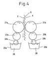
- Figs. 4 and 5 a case of applying an adhesive 26 to the wave tops 6 of a corrugated foil 4.
- the adhesive 26 is applied to a flat foil 3
- the adhesive 26 may be applied to the areas not to be contacted with the corrugated foil, and to be coated later with the catalytic materials. These areas will then be covered with the brazing filler metal in powder and, as a consequence, an excessive amount of the brazing filler metal will be consumed.
- the foil material of the flat foil may be alloyed at the areas covered with the brazing filler metal by the elements contained in it, adversely affecting mechanical properties of the flat foil 3.
- the adhesive 26 is applied to the wave tops 6 of a corrugated foil 4 as described in the item (3) of the present invention, the adhesive 26 is applied to the corrugated foil only on the contact lines 5 with the flat foil and the brazing filler metal is deposited only on the contact lines 5 of the flat and corrugated foils, which is more preferable than the above case.
- pairs of second rolls 23 and third rolls 24 are equipped between the adhesive tanks 22 and the adhesive applicator rolls 21, and these rolls rotate as the applicator rolls 21 do.
- the third rolls 24 are partially immersed in the adhesive 26 in the adhesive tanks 22 and the adhesive 26 covers the surfaces of the third rolls as they rotate.
- the adhesive 26 on the surfaces of the third rolls is transferred onto the surfaces of the second rolls as they rotate, and then the adhesive 26 on the surfaces of the second rolls is transferred onto the surfaces of the adhesive applicator rolls, to be finally transferred from the surfaces of the adhesive applicator rolls onto the wave tops 6 of the corrugated foil passing between them.
- the second rolls 23 and the third rolls 24 can be omitted as the case may be.
- the pairs of the adhesive applicator rolls, second rolls, third rolls, confronting each other, and adhesive tanks constitute an adhesive application apparatus 25.
- FIG. 5 is a case of applying an adhesive 26 to the wave tops 6 corresponding to two bonding portions, namely the bonding portion 17 at the gas inlet end of the honeycomb body and the bonding portion 18 inside the honeycomb body over a cross section which is located away from one or both ends thereof in the axial direction.
- a pair of adhesive applicator rolls (21a and 21b) and the accompanying adhesive application apparatus are provided for applying the adhesive 26 to the width edge portions 27 of a corrugated foil corresponding to the bonding portion 17 at the end of the honeycomb body.
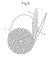
- the honeycomb body 1 After the application of the adhesive 26 to the flat foil 3 or the corrugated foil 4, the flat foil 3 and the corrugated foil 4 are wound in layers, as shown in Fig. 6, to form the honeycomb body 1.
- the honeycomb body 1 may be encased in the cylindrical metal jacket 2 at this stage.
- the method of sucking up the adhesive 33 is employed for the bonding portion 16 over the full axial length of the honeycomb body outer layers.
- the honeycomb body 1 formed by winding the flat and corrugated foils is placed to come in contact with the surface of the liquid adhesive 33 at a part of one of its end faces.
- the part of the honeycomb body to contact the surface of the liquid adhesive 33 is the part of one of its end faces corresponding to the bonding portion 16 over the full axial length of the honeycomb body outer layers. Since the ends of the contact lines 5 of the flat and corrugated foils are exposed at the end faces of the honeycomb body, the adhesive 33 contacts the contact lines.
- the adhesive 33 is sucked up along the contact lines 5 from the end in contact with the liquid adhesive 33 over the full axial length of the honeycomb body to the other end by the capillary phenomenon.
- the adhesive 33 is deposited all along the contact lines 5 of the flat foil 3 and the corrugated foil 4 of the honeycomb body as shown in Fig. 7.
- the adhesive is deposited evenly along the contact lines and, consequently, the consumption of the brazing filler metal is reduced and the alloyed parts of the foils forming the honeycomb body are minimized.
- the flat and corrugated foils contact each other tightly by elastic deformation of the foils once they are wound to form a honeycomb body, and, for this reason, the adhesive is evenly deposited along every contact line by the method of sucking up the adhesive according to the present invention, eliminating inappropriate adhesive application as seen in the cases of the adhesive application methods using the rolls.
- the contact of the honeycomb body with the liquid adhesive 33 at one or both end faces has to be limited to the outer layers 12 of the honeycomb body where the flat and corrugated foils have to be bonded all through the axial length of the honeycomb body.
- An elastic porous body such as a sponge or a cavernous body, a metal porous body, a ceramic porous body, etc. can be used as the porous body 31.
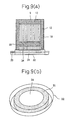
- the adhesive can be deposited as described above, specifically, by forming the porous body 31 in a ring shape as shown in Fig. 8(b) and making the inner diameter of the ring equal to the diameter of the innermost layer of the bonding portion 16 of the outer layers of the honeycomb body, as described in the item (6).
- the outer diameter of the ring is set equal to or larger than the outer diameter of the honeycomb body 1.
- the ring-shaped porous body 31 is impregnated with the adhesive 33 by placing it in an adhesive tank 32.
- the honeycomb body 1 contacts the liquid adhesive 33 at one or both end faces by making it contact the porous body 31 coaxially as shown in Fig. 8(a).
- the porous body 31 is preferable to be of the racetrack shape accordingly.
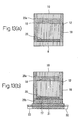
- the porous body 31 may also be of a disc shape with a shield plate 34 placed on it as illustrated in Fig. 9.
- the outer diameter of the shield plate 34 is preferable to be equal to the diameter of the innermost layer of the bonding portion 16 of the outer layers of the honeycomb body.
- the honeycomb body 1 is placed on the porous body 31 coaxially with the shield plate 34. Since it will be only at the area outside the shield plate 34 that one or both end faces of the honeycomb body 1 contacts the porous body 31 by the above arrangement, only the area of one or both end faces of the honeycomb body corresponding to the bonding portion 16 over the full axial length of the honeycomb body outer layers will contact the liquid adhesive 33 permeating through the porous body.
- an elastic porous body comprising of sponge, cavernous material or the like as the porous body 31 for realizing a good contact with the honeycomb body.
- the honeycomb body After applying the adhesives 26 and depositing the adhesives 33 at the portions of the honeycomb body to be brazed as explained above, the honeycomb body is fed with the brazing filler metal in powder, which is deposited only at the areas covered with the adhesives 26 and 33. The brazing filler metal in powder not caught by the adhesives is discharged from the honeycomb body.
- the honeycomb body 1 may be encased in the cylindrical metal jacket 2 at any of the following stages: upon winding the flat and corrugated foils in layers into a honeycomb body, upon sucking up the adhesive 33 to the bonding portion, or upon depositing the brazing filler metal in powder.
- the outer surface of the honeycomb body 1 is bonded to the inner surface of the cylindrical metal jacket 2 usually by attaching a foil of a brazing filler metal or depositing a brazing filler metal in powder.
- the adhesive 33 may be deposited along the contact lines of the wave tops of the corrugated foil and the inner surface of the cylindrical metal jacket 2 by the method of sucking up the adhesive after inserting the honeycomb body 1 into the metal jacket 2.
- bonding of the honeycomb body is completed by brazing the bonding portions by charging the honeycomb body encased in the cylindrical metal jacket into a high temperature furnace to heat it and melting the brazing filler metal in powder deposited along the contact lines of the flat and corrugated foils.
- a solution, for example, of polyvinyl alcohol is used as the liquid adhesive 33 in the method of sucking up the adhesive 33 according to the present invention.
- the surface tension of the adhesive 33 can be controlled by adding a surface active agent to it as the case may be, and it is thus possible to control the condition to suck up the adhesive along the contact lines of the flat and corrugated foils. It has to be noted that the viscosity of the liquid adhesive 33 has to be within a suitable range lower than a prescribed value, because the adhesive 33 will not be sucked up smoothly if its viscosity is too high.
- Polyvinyl alcohol or high molecular polymers may be used as the adhesive 26 to be applied partly to the edge portions or the portions away from the edges of the metal foil according to the present invention. If the adhesive 26 has too low a viscosity, it will spread by surface tension between the contact surfaces of the flat and corrugated foils when they are wound in layers. For this reason the adhesive 26 has to have a viscosity within a suitable range above a prescribed value.
- the sucking-up of the liquid adhesive 33 is kept smooth and the adhesive 26 is prevented from spreading too much by making the viscosity of the liquid adhesive 33 lower than that of the adhesive 26 as described in the item (7).
- the adhesive 26 When the adhesive 26 is applied to the flat or corrugated foil, if the adhesive 26 is applied also to the areas to be included in the bonding portion 16 over the full axial length of the honeycomb body outer layers, and if the adhesive 33 is sucked up thereafter, the adhesive 33 cannot be sucked up beyond the portions where the adhesive 26 has already been applied. When applying the adhesive 26, therefore, it is necessary not to apply it to the areas to be included in the bonding portion 16 over the full axial length of the honeycomb body outer layers.
- Fig. 8 shows an example of a method of manufacturing a honeycomb body having the bonding portion 16 over the full axial length of the honeycomb body in its outer layers and the bonding portion 17 which is located at the gas inlet end of the honeycomb body
- Fig. 9 another to manufacture a honeycomb body having the bonding portion 16 over the full axial length of the honeycomb body outer layers, the bonding portion 17 which is located at the gas inlet end of the honeycomb body and a bonding portion 18 inside the honeycomb body over a cross section.
- the adhesive 26 is applied to the areas of the foil corresponding to the bonding portion 17 which is located at the gas inlet end of the honeycomb body and the bonding portion 18 inside the honeycomb body over a cross section before winding the flat and corrugated foils, and the adhesive 33 is deposited at the bonding portion 16 over the full axial length of the honeycomb body by the method of sucking up the adhesive 33 after forming the flat and corrugated foils into a honeycomb body.
- the adhesive 33 is deposit at the bonding portion 17 which is located at one or both ends of the honeycomb body by the method of sucking up the adhesive 33.
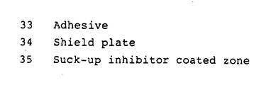
- the adhesive 26 is applied to the bonding portion 18 inside the honeycomb body over a cross section before winding the flat and corrugated foils and, besides, suck-up inhibitor coated zones 35 are provided on the surface of the flat foil 3 by applying an agent to prevent the sucking-up of the adhesive such as fat, grease, oil, etc. also before winding the foils.
- the adhesive 33 is not sucked up beyond the suck-up inhibitor coated zone 35 owing to poor wettability of the suck-up inhibitor coated zone 35 with the adhesive 33.
- the adhesive 33 is sucked up along the contact lines of the flat and corrugated foils in the whole section of the honeycomb body.
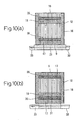
- the adhesive 33 is sucked up over the full axial length because no suck-up inhibitor coated zone 35 is provided in the bonding portion 16, the adhesive 33 is sucked up only within the end portion 17 of the honeycomb body in the inner layers 13 owing to the existence of the suck-up inhibitor coated zone 35. It is also possible to deposit the adhesive 33 in the bonding portions 17 at both the ends of the honeycomb body 1, by turning it upside down after the above step so as to make the gas outlet end face 10 contact the porous body at the inner layers as shown in Fig. 10(b).
- the suck-up inhibitor coated zone 35 is provided, in the axial direction, at the inside of, and contiguous to a portion to be formed as the bonding portion 17 which is located at one or both ends of honeycomb body.
- the suck-up inhibitor coated zones 35 are provided, in the axial direction, at the inside of, and contiguous to a portion to be formed as the bonding portion 17 which is located at the gas inlet end of honeycomb body and at the inside of, and contiguous to a portion to be formed as the bonding portion 17 which is located at the gas outlet end of honeycomb body.
- the suck-up inhibitor coated zone 35 is provided, in the axial direction, at the inside of, and contiguous to a portion to be formed as the bonding portion 17 which is located at the gas inlet end of honeycomb body.
- the suck-up inhibitor is coated on the surface of the flat foil 3 in the above examples, however, it can be coated on the surface of the corrugated foil 4 or both foils.
- the following sequence of procedures as shown in Fig. 11 is also viable: to apply the adhesive 26 to the areas of the corrugated foil corresponding to the bonding portion 18 inside the honeycomb body over a cross section and apply the fat, grease, oil, etc. to the areas of the flat foil corresponding to the suck-up inhibitor coated zone 35; to wind the flat and corrugated foils into a honeycomb body thereafter; to make one or both end faces of the honeycomb body contact the porous body 31 at the outer layers as shown in Fig.
- the adhesive 33 can be sucked up along both the bonding portion 17 in the outer layers and the bonding portion at the axial core 7 at the same time, as shown in Fig. 12(a), by using an annular porous body 31a and a columnar porous body 31b as a porous body as shown in Fig. 12(b).
- the adhesive 33 is to be deposited all along the axial length of a honeycomb body 1 having a long axial length by the method of sucking up the adhesive, there may occur a problem that too much of the adhesive 33 is deposited near the end face of the honeycomb body contacting the surface of the liquid adhesive 33 or insufficient adhesive reaches the end of the honeycomb body opposite the end contacting the surface of the liquid adhesive 33.
- a sufficiently strong bonding portion can be formed in the bonding portion 20 all along the axial length in the outer layers, even when the method of applying the adhesive 26 has been employed before winding the flat and corrugated foils for the rest (the portion 20a excluding the gas inlet end portion 20b) of the axial length.
- the bonding portion 17 at the gas inlet end of the honeycomb body for avoiding insufficient or uneven application of the adhesive, it is preferable to employ the method of sucking up the adhesive 33 rather than the method of applying the adhesive 26 before winding the flat and corrugated foils, because the bonding portion 17 is meant to secure the strength of the inner layers of the honeycomb body.
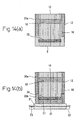
- Fig. 13(a) shows the condition before the adhesive 33 is sucked up.
- the adhesive 26 has been applied to the areas corresponding to the bonding portion 18 inside the honeycomb body over a cross section and the portion 20a excluding the portion which is located at the gas inlet end of the honeycomb body from the bonding portion over the full axial length of the honeycomb body outer layers.
- a suck-up inhibitor coated zone 35 has also been provided near the gas inlet end face 9 of the honeycomb body by applying fat, grease, oil, etc. to the flat foil.
- the adhesive 33 is deposited along the contact lines 5 of the flat and corrugated foils by making the whole gas inlet end face 9 contact the surface of the liquid adhesive 33 to suck it up as shown in Fig. 13(b).
- the adhesive 33 is sucked up into the gas inlet side portion 20b of the bonding portion over the full axial length of the honeycomb body outer layers up to the lower end of the portion where the adhesive 26 has been applied and, in the inner layers of the honeycomb body, up to the lower end of the suck-up inhibitor coated zone 35, achieving the condition shown in Fig. 13(b).
- the axial length of the gas inlet side portion 20b of the bonding portion over the full axial length of the honeycomb body outer layers can be made longer than the axial length of the bonding portion 17 at the end of the honeycomb body as shown in Fig. 14. By doing so, the bonding portion 20 over the full axial length of the honeycomb body outer layers can be made more sound than in the case shown in Fig. 13.
- the inventions according to the items (9) to (12) are applications of the inventions according to the items (2) to (4) and (7) to the invention according to the item (8), and the inventions according to the items (9) to (12) realize the same effects of the inventions according to the items (2) to (4) and (7) more efficiently.
- the reason why the flat foil 3 and the corrugated foil 4 are wound in layers, one over the other, in the present invention is that a cell formed between the corrugated foil in one wavelength and the flat foil by winding the foils in layers is used as a path of the emission gas from a automobile engine. Since the purpose of the winding is to form the cells, it is not imperative that the flat foil 3 should be dead flat as far as the purpose is attained.
- the flat foil 3 has corrugation 14 as shown in Fig. 15.
- the wavelength of the corrugation 14 of the flat foil 3 is shorter than that of the corrugated foil 4 and the wave height of the corrugation 14 of the flat foil 3 is also smaller than that of the corrugated foil 4.
- the formation of the cells, or the paths of the emission gas, by winding the flat foil 3 and corrugated foil 4 in layers is not different from the case of winding a flat foil having no corrugation with a corrugated foil.
- the wavelength of the corrugation 14 of the flat foil 3 may either be shorter than that of the corrugated foil 4 as shown in Fig. 15(a) or longer than the same as shown in Fig. 15(b). It is preferable for forming a honeycomb body. having good cell shapes that the wavelength of the corrugation 14 of the flat foil 3 is 85% or less of the same of the corrugated foil 4 and that the wave height of the corrugation 14 of the flat foil 3 is 50% or less of the same of the corrugated foil 4.
- the use of a flat foil 3 having the corrugation 14 specified above increases elasticity of the flat foil 3 and improves the service life of the honeycomb body.
- a honeycomb body for metal catalyst support use manufactured by a method according to the present invention has high structural reliability against thermal load and stress imposed on a catalyst support and resistance against the fracture problem caused by a misfire of a automobile engine, as a result of bonding the foils over the full axial length of the honeycomb body outer layers and at one or both ends of the honeycomb body inner layers and/or at another portion of the honeycomb body inner layers which is located inside the honeycomb body over a cross section.
- the present invention eliminates poor bonding and excessive consumption of the brazing filler metal and realizes excellent bonding of the foils, compared with the methods to apply the adhesive 26 to a flat or corrugated foil using rolls, because the adhesive is deposited by a method of sucking it up after the flat and corrugated foils are wound in layers; at the bonding portion 16 over the full axial length of the honeycomb body outer layers according to the items (1) to (7) of the present invention and at the bonding portion 17 which is located at the gas inlet end of the honeycomb body according to the item (8) of the present invention.
- the present invention it is possible to evenly deposit the adhesive along the contact lines of the foils and evenly braze the bonding portion over the full axial length even when the corrugated foil is bent in its width direction.
- the equipment cost of the honeycomb body manufacturing facilities can be lowered, because the application of an adhesive by rolls can be limited only to the bonding portion at one or both ends of the honeycomb body and/or the bonding portion inside the honeycomb body over a cross section which is located away from one or both ends thereof in the axial direction.
- the present invention employs also a method of applying the adhesive by rolls, it is possible to apply the adhesive selectively to the areas of a foil corresponding to a bonding portion inside a honeycomb body over a cross section and, therefore, it is possible to manufacture a honeycomb body conforming to the countermeasure against an engine misfire problem.
Landscapes
- Chemical & Material Sciences (AREA)
- Engineering & Computer Science (AREA)
- Chemical Kinetics & Catalysis (AREA)
- Health & Medical Sciences (AREA)
- Toxicology (AREA)
- Combustion & Propulsion (AREA)
- Mechanical Engineering (AREA)
- General Engineering & Computer Science (AREA)
- Environmental & Geological Engineering (AREA)
- Materials Engineering (AREA)
- Organic Chemistry (AREA)
- Biomedical Technology (AREA)
- Analytical Chemistry (AREA)
- General Chemical & Material Sciences (AREA)
- Oil, Petroleum & Natural Gas (AREA)
- Catalysts (AREA)
Abstract
Description
Claims (13)
- A method of manufacturing a honeycomb body formed by winding a flat metal foil and a corrugated metal foil in layers and brazing them at the bonding portion over the full axial length of the honeycomb body outer layers, at a bonding portion which is located at one or both ends of the honeycomb body, and/or at a bonding portion inside the honeycomb body over a cross section which is located away from one or both ends thereof in the axial direction, characterized by:(a) applying an adhesive to the portions to be brazed of the flat or corrugated foil corresponding to the bonding portion which is located at one or both ends of the honeycomb body and/or the bonding portion inside the honeycomb body over a cross section which is located away from one or both ends thereof in the axial direction;(b) then, winding the flat and corrugated foils in layers to form a honeycomb body;(c) then, depositing a liquid adhesive at the portion of the honeycomb body corresponding to the bonding portion over the full axial length of the honeycomb body outer layers by making the portion of one or both end faces of the honeycomb body corresponding to the bonding portion over the full axial length of the honeycomb body outer layers contact the surface of the liquid adhesive and having the adhesive sucked up along contact lines of the flat and corrugated foils; and(d) then, feeding a brazing filler metal in powder to the honeycomb body so as to have it deposited at the portions where the adhesives have been applied or deposited.
- A method of manufacturing a honeycomb body according to claim 1, characterized in that the bonding portion over the full axial length of the honeycomb body outer layers covers 1/3 or less of the radius of the honeycomb body from its outermost layer toward the center thereof.
- A method of manufacturing a honeycomb body according to claim 1 or 2, characterized in that the portions of the flat foil or the corrugated foil to which the adhesive is applied are the portions corresponding to the wave tops of the corrugated foil.
- A method of manufacturing a honeycomb body according to any one of claims 1 to 3, characterized by applying the adhesive to the portions of the flat foil or the corrugated foil by making rolls covered with the adhesive on the surfaces contact the flat or corrugated foil.
- A method of manufacturing a honeycomb body according to any one of claims 1 to 4, characterized by depositing the liquid adhesive at the portion of the honeycomb body corresponding to the bonding portion over the full axial length of the honeycomb body outer layers by making a porous body impregnated with the liquid adhesive contact the portion of one or both end faces of the honeycomb body corresponding to the bonding portion over the full axial length of the honeycomb body outer layers and, thus, having the adhesive sucked up along the contact lines of the flat and corrugated foils.
- A method of manufacturing a honeycomb body according to claim 5, characterized in that the porous body has an annular shape.
- A method of manufacturing a honeycomb body according to any one of claims 1 to 6, characterized in that the viscosity of the liquid adhesive to be sucked up to the honeycomb body is lower than that of the adhesive to be applied by the rolls.
- A method of manufacturing a honeycomb body formed by winding a flat metal foil and a corrugated metal foil in layers and brazing them at the bonding portion over the full axial length of the honeycomb body outer layers, at a bonding portion which is located at one or both ends of the honeycomb body, and/or at a bonding portion inside the honeycomb body over a cross section which is located away from one or both ends thereof in the axial direction, characterized by:(a) applying an adhesive to the portions to be brazed of the flat or corrugated foil corresponding to the bonding portion inside the honeycomb body over a cross section which is located away from one or both ends thereof in the axial direction and to the portion excluding the portion which is located at the gas inlet end of the honeycomb'body from the bonding portion over the full axial length of the honeycomb body outer layers;(b) then, winding the flat foil and the corrugated foil in layers to form a honeycomb body;(c) then, depositing a liquid adhesive at the portion which is located at the gas inlet end out of the bonding portion over the full axial length of the honeycomb body outer layers and the bonding portion which is located at one or both ends of the honeycomb body, by making the gas inlet end face of the honeycomb body adhere to the surface of the liquid adhesive and having the adhesive sucked up along contact lines of the flat and corrugated foils; and(d) then, feeding a brazing filler metal in powder to the honeycomb body so as to have it deposited at the portions where the adhesives have been applied or deposited.
- A method of manufacturing a honeycomb body according to claim 8, characterized in that the bonding portion over the full axial length of the honeycomb body outer layers covers 1/3 or less of the radius of the honeycomb body from its outermost layer toward the center.
- A method of manufacturing a honeycomb body according to claim 8 or 9, characterized in that the portions of the flat foil or the corrugated foil to which the adhesive is applied are the portions corresponding to the wave tops of the corrugated foil.
- A method of manufacturing a honeycomb body according to any one of claims 8 to 10, characterized by applying the adhesive to the portions of the flat foil or the corrugated foil by making rolls covered with the adhesive on the surface contact the flat or corrugated foil.
- A method of manufacturing a honeycomb body according to any one of claims 8 to 11, characterized in that the viscosity of the liquid adhesive to be sucked up to the honeycomb body is lower than that of the adhesive to be applied by the rolls.
- A method of manufacturing a honeycomb body according to any one of claims 1 to 12, characterized in that the flat foil has corrugation and the wave height of the corrugation is smaller than the wave height of the corrugated foil.
Applications Claiming Priority (5)
| Application Number | Priority Date | Filing Date | Title |
|---|---|---|---|
| JP2000308928 | 2000-10-10 | ||
| JP2000308928 | 2000-10-10 | ||
| JP2001205592 | 2001-07-06 | ||
| JP2001205592 | 2001-07-06 | ||
| PCT/JP2001/007749 WO2002030566A1 (en) | 2000-10-10 | 2001-09-06 | Honeycomb body manufacturing method |
Publications (3)
| Publication Number | Publication Date |
|---|---|
| EP1475150A4 EP1475150A4 (en) | 2004-11-10 |
| EP1475150A2 true EP1475150A2 (en) | 2004-11-10 |
| EP1475150B1 EP1475150B1 (en) | 2012-08-22 |
Family
ID=26601765
Family Applications (1)
| Application Number | Title | Priority Date | Filing Date |
|---|---|---|---|
| EP01963483A Expired - Lifetime EP1475150B1 (en) | 2000-10-10 | 2001-09-06 | Honeycomb body manufacturing method |
Country Status (3)
| Country | Link |
|---|---|
| US (1) | US6908028B2 (en) |
| EP (1) | EP1475150B1 (en) |
| WO (1) | WO2002030566A1 (en) |
Cited By (3)
| Publication number | Priority date | Publication date | Assignee | Title |
|---|---|---|---|---|
| CN102179592A (en) * | 2011-04-20 | 2011-09-14 | 浙江天泽环境科技有限公司 | Method and device for soldering flux application |
| CN108686508A (en) * | 2017-03-30 | 2018-10-23 | 日本碍子株式会社 | Honeycomb structure |
| WO2025202483A1 (en) * | 2024-03-28 | 2025-10-02 | Emitec Technologies GmbH | Honeycomb structure and method for producing a structured layer |
Families Citing this family (10)
| Publication number | Priority date | Publication date | Assignee | Title |
|---|---|---|---|---|
| DE10338360A1 (en) * | 2003-08-21 | 2005-03-31 | Emitec Gesellschaft Für Emissionstechnologie Mbh | Method and device for producing a honeycomb body |
| DE10345910A1 (en) * | 2003-10-02 | 2005-04-21 | Emitec Emissionstechnologie | Method for producing a metallic honeycomb body with a layer length difference |
| EP1557545A3 (en) * | 2004-01-21 | 2006-03-29 | Ecocat OY | Metallic catalyst for treating exhaust gases and method and apparatus for manufacturing the same |
| EP1714727A3 (en) * | 2005-04-20 | 2006-12-27 | Behr GmbH & Co. KG | Process and device for applying solder |
| US7837144B2 (en) * | 2006-08-11 | 2010-11-23 | Techno-Sciences, Inc. | Fluid-driven artificial muscles as mechanisms for controlled actuation |
| US7931240B2 (en) * | 2006-08-11 | 2011-04-26 | Techno-Sciences, Inc. | Cellular support structures used for controlled actuation of fluid contact surfaces |
| WO2015086514A1 (en) * | 2013-12-10 | 2015-06-18 | Höganäs Ab (Publ) | Method for applying paste on a surface of elevated portions of a component, apparatus suitable for carrying out the method and product manufactured by the method |
| EP3539658B1 (en) | 2014-02-12 | 2020-09-09 | NIPPON STEEL Chemical & Material Co., Ltd. | Metal substrate for catalytic converters |
| CN107683176A (en) * | 2015-10-06 | 2018-02-09 | 新日铁住金高新材料股份有限公司 | Catalyst supporting substrate and catalyst carrier |
| CN109848558B (en) * | 2019-01-09 | 2021-04-20 | 北京安达泰克科技有限公司 | Method for manufacturing honeycomb structure |
Family Cites Families (18)
| Publication number | Priority date | Publication date | Assignee | Title |
|---|---|---|---|---|
| DE2924592C2 (en) | 1979-06-19 | 1983-05-26 | Süddeutsche Kühlerfabrik Julius Fr. Behr GmbH & Co KG, 7000 Stuttgart | Method for producing a carrier matrix for a catalytic reactor for exhaust gas purification in internal combustion engines of motor vehicles |
| DE3818512A1 (en) | 1988-05-31 | 1989-12-07 | Interatom | METHOD FOR GLUING AND SOLDERING A METAL CATALYST SUPPORT BODY AND RELATED DEVICE |
| EP0389645B1 (en) | 1988-10-04 | 1995-03-22 | Nippon Steel Corporation | Metal carrier having thermal fatigue resistance for automobile exhaust gas cleaning catalysts |
| JP2548796B2 (en) * | 1989-04-03 | 1996-10-30 | 新日本製鐵株式会社 | Brazing method for honeycomb structure |
| JP2732889B2 (en) * | 1989-04-14 | 1998-03-30 | 新日本製鐵株式会社 | Metallic carrier for automotive exhaust gas catalysts with good thermal stress and thermal fatigue resistance |
| JP2634669B2 (en) * | 1989-06-01 | 1997-07-30 | 日産自動車株式会社 | Metal honeycomb catalyst device |
| EP0437626B1 (en) * | 1989-08-04 | 1994-12-28 | Showa Aircraft Industry Co., Ltd. | Heat resistant structure and method of manufacture thereof |
| EP0474909B1 (en) * | 1990-09-13 | 1994-01-12 | Nippon Steel Corporation | Method of soldering honeycomb body |
| JP2512622B2 (en) | 1990-10-09 | 1996-07-03 | 新日本製鐵株式会社 | Metal carrier for automobile exhaust gas catalyst with good durability |
| JPH04150948A (en) * | 1990-10-12 | 1992-05-25 | Nippon Steel Corp | Metal carrier supporting exhaust gas purifying catalyst having intermittently bonded honeycomb part and preparation thereof |
| JP2804397B2 (en) | 1991-10-07 | 1998-09-24 | ダイハツ工業株式会社 | Supply device for different diameter parts |
| JP2543636Y2 (en) * | 1992-04-15 | 1997-08-13 | 新日本製鐵株式会社 | Metal carrier for exhaust gas purification |
| JP2510966B2 (en) * | 1993-08-18 | 1996-06-26 | 坂本工業株式会社 | Method of attaching binder to metal honeycomb carrier |
| EP0693316B1 (en) * | 1994-02-08 | 1999-08-25 | Nippon Steel Corporation | Metal honeycomb for catalyst for automobiles and method of manufacturing the same |
| DE4416539C1 (en) * | 1994-05-10 | 1995-07-20 | Emitec Emissionstechnologie | Method for applying solder to metal structures using solder powder |
| JPH0824670A (en) * | 1994-07-11 | 1996-01-30 | Usui Internatl Ind Co Ltd | Metal honeycomb body for exhaust gas purification |
| JP4425463B2 (en) * | 1998-01-27 | 2010-03-03 | エミテック ゲゼルシヤフト フユア エミツシオンス テクノロギー ミツト ベシユレンクテル ハフツング | Brazing method of equipment |
| US20020086179A1 (en) * | 2000-05-19 | 2002-07-04 | Wittebrood Adrianus Jacobus | Composite metal panel |
-
2001
- 2001-09-06 EP EP01963483A patent/EP1475150B1/en not_active Expired - Lifetime
- 2001-09-06 WO PCT/JP2001/007749 patent/WO2002030566A1/en not_active Ceased
- 2001-09-06 US US10/149,522 patent/US6908028B2/en not_active Expired - Lifetime
Cited By (3)
| Publication number | Priority date | Publication date | Assignee | Title |
|---|---|---|---|---|
| CN102179592A (en) * | 2011-04-20 | 2011-09-14 | 浙江天泽环境科技有限公司 | Method and device for soldering flux application |
| CN108686508A (en) * | 2017-03-30 | 2018-10-23 | 日本碍子株式会社 | Honeycomb structure |
| WO2025202483A1 (en) * | 2024-03-28 | 2025-10-02 | Emitec Technologies GmbH | Honeycomb structure and method for producing a structured layer |
Also Published As
| Publication number | Publication date |
|---|---|
| US20030073561A1 (en) | 2003-04-17 |
| EP1475150A4 (en) | 2004-11-10 |
| WO2002030566A1 (en) | 2002-04-18 |
| US6908028B2 (en) | 2005-06-21 |
| WO2002030566A9 (en) | 2004-05-13 |
| EP1475150B1 (en) | 2012-08-22 |
Similar Documents
| Publication | Publication Date | Title |
|---|---|---|
| US6908028B2 (en) | Method of manufacturing honeycomb body | |
| KR100357741B1 (en) | Exhaust gas cleaning catalyst metal honey comb element, method for manufacturing the same, and metal foil | |
| US7601672B2 (en) | High Al stainless steel sheet and honeycomb bodies employing them | |
| WO1994029062A1 (en) | Exhaust gas cleaning metal carrier and method of manufacturing the same | |
| JP3949265B2 (en) | Method for incorporating ceramic honeycomb structure and holding member used in the method | |
| KR100688007B1 (en) | Method for producing sintered honeycomb body | |
| CN1076239C (en) | Brazed metal honeycomb manufacturing method | |
| CN100356043C (en) | Tuned catalyst substrate with corrugated shell and method of making the same | |
| CN101268261A (en) | Honeycomb body with end-side brazing regions | |
| KR19990044009A (en) | Method of producing honeycomb structures from two different types of metal sheets | |
| US20080069717A1 (en) | High A1 stainless steel sheet and double layered sheet, process for their fabrication, honeycomb bodies employing them and process for their production | |
| JP2003080660A (en) | Method for manufacturing honeycomb body | |
| JP3338703B1 (en) | Method for manufacturing honeycomb body | |
| JPH0751581A (en) | Exhaust gas purification metal carrier excellent in heat fatigue resistance and vibration resistance, and method for producing the same | |
| JP2000051711A (en) | Exhaust gas purifying catalyst carrier and method for producing the same | |
| JP3544451B2 (en) | Metal carrier for catalytic converter and method for producing the same | |
| JP3788819B2 (en) | Metal carrier for exhaust gas purification catalyst | |
| JPH0838912A (en) | Manufacturing method of metal carrier | |
| JPH08323213A (en) | Production of metal honeycomb member | |
| JP3039670B2 (en) | Exhaust gas purification device | |
| JP2598242B2 (en) | Metal honeycomb body for dissolving and method of manufacturing the same | |
| JPH10337481A (en) | Metal carrier for catalytic converter and method for producing the same | |
| JPH06327983A (en) | Production of honeycomb body | |
| JP2002191982A (en) | Metal carrier and method for producing the same | |
| JPH07173607A (en) | Surface-treated steel sheet with excellent brazability |
Legal Events
| Date | Code | Title | Description |
|---|---|---|---|
| PUAI | Public reference made under article 153(3) epc to a published international application that has entered the european phase |
Free format text: ORIGINAL CODE: 0009012 |
|
| 17P | Request for examination filed |
Effective date: 20020801 |
|
| A4 | Supplementary search report drawn up and despatched |
Effective date: 20040922 |
|
| AK | Designated contracting states |
Kind code of ref document: A2 Designated state(s): AT BE CH CY DE DK ES FI FR GB GR IE IT LI LU MC NL PT SE TR |
|
| 17Q | First examination report despatched |
Effective date: 20080718 |
|
| GRAP | Despatch of communication of intention to grant a patent |
Free format text: ORIGINAL CODE: EPIDOSNIGR1 |
|
| RBV | Designated contracting states (corrected) |
Designated state(s): DE FI FR GB IT |
|
| GRAS | Grant fee paid |
Free format text: ORIGINAL CODE: EPIDOSNIGR3 |
|
| RAP1 | Party data changed (applicant data changed or rights of an application transferred) |
Owner name: NIPPON STEEL CORPORATION |
|
| GRAA | (expected) grant |
Free format text: ORIGINAL CODE: 0009210 |
|
| RIN1 | Information on inventor provided before grant (corrected) |
Inventor name: KASUYA, MASAYUKI, C/O NIPPON STEEL CO.NAGOYA WORKS Inventor name: UTSUMI, TORU, C/O NIPPON STEEL CORPORATION Inventor name: SHINODA, TAKESHI, C/O NIPPON STEEL CO.NAGOYA WORKS Inventor name: IMAI, ATSUHIKO, C/O NIPPON STEEL CORPORATION Inventor name: IWAMI, KAZUTOSHI, C/O NIPPON STEEL CORPORATION |
|
| AK | Designated contracting states |
Kind code of ref document: B1 Designated state(s): DE FI FR GB IT |
|
| REG | Reference to a national code |
Ref country code: GB Ref legal event code: FG4D |
|
| REG | Reference to a national code |
Ref country code: DE Ref legal event code: R096 Ref document number: 60147020 Country of ref document: DE Effective date: 20121018 |
|
| RAP2 | Party data changed (patent owner data changed or rights of a patent transferred) |
Owner name: NIPPON STEEL & SUMITOMO METAL CORPORATION |
|
| REG | Reference to a national code |
Ref country code: DE Ref legal event code: R081 Ref document number: 60147020 Country of ref document: DE Owner name: NIPPON STEEL SUMIKIN MATERIALS CO., LTD., JP Free format text: FORMER OWNER: NIPPON STEEL CORP., TOKIO/TOKYO, JP Effective date: 20120822 Ref country code: DE Ref legal event code: R081 Ref document number: 60147020 Country of ref document: DE Owner name: NIPPON STEEL SUMIKIN MATERIALS CO., LTD., JP Free format text: FORMER OWNER: NIPPON STEEL CORPORATION, TOKIO/TOKYO, JP Effective date: 20130227 Ref country code: DE Ref legal event code: R082 Ref document number: 60147020 Country of ref document: DE Representative=s name: VOSSIUS & PARTNER, DE Effective date: 20130227 Ref country code: DE Ref legal event code: R081 Ref document number: 60147020 Country of ref document: DE Owner name: NIPPON STEEL & SUMITOMO METAL CORPORATION, JP Free format text: FORMER OWNER: NIPPON STEEL CORPORATION, TOKIO/TOKYO, JP Effective date: 20130227 Ref country code: DE Ref legal event code: R081 Ref document number: 60147020 Country of ref document: DE Owner name: NIPPON STEEL & SUMITOMO METAL CORPORATION, JP Free format text: FORMER OWNER: NIPPON STEEL CORP., TOKIO/TOKYO, JP Effective date: 20120822 Ref country code: DE Ref legal event code: R082 Ref document number: 60147020 Country of ref document: DE Representative=s name: VOSSIUS & PARTNER PATENTANWAELTE RECHTSANWAELT, DE Effective date: 20130227 Ref country code: DE Ref legal event code: R081 Ref document number: 60147020 Country of ref document: DE Owner name: NIPPON STEEL & SUMIKIN MATERIALS CO., LTD., JP Free format text: FORMER OWNER: NIPPON STEEL CORPORATION, TOKIO/TOKYO, JP Effective date: 20130227 Ref country code: DE Ref legal event code: R081 Ref document number: 60147020 Country of ref document: DE Owner name: NIPPON STEEL & SUMIKIN MATERIALS CO., LTD., JP Free format text: FORMER OWNER: NIPPON STEEL CORP., TOKIO/TOKYO, JP Effective date: 20120822 |
|
| PLBE | No opposition filed within time limit |
Free format text: ORIGINAL CODE: 0009261 |
|
| STAA | Information on the status of an ep patent application or granted ep patent |
Free format text: STATUS: NO OPPOSITION FILED WITHIN TIME LIMIT |
|
| 26N | No opposition filed |
Effective date: 20130523 |
|
| PG25 | Lapsed in a contracting state [announced via postgrant information from national office to epo] |
Ref country code: IT Free format text: LAPSE BECAUSE OF NON-PAYMENT OF DUE FEES Effective date: 20120906 |
|
| REG | Reference to a national code |
Ref country code: DE Ref legal event code: R097 Ref document number: 60147020 Country of ref document: DE Effective date: 20130523 |
|
| PGFP | Annual fee paid to national office [announced via postgrant information from national office to epo] |
Ref country code: GB Payment date: 20140903 Year of fee payment: 14 |
|
| PGFP | Annual fee paid to national office [announced via postgrant information from national office to epo] |
Ref country code: FR Payment date: 20140906 Year of fee payment: 14 |
|
| GBPC | Gb: european patent ceased through non-payment of renewal fee |
Effective date: 20150906 |
|
| REG | Reference to a national code |
Ref country code: FR Ref legal event code: ST Effective date: 20160531 |
|
| PG25 | Lapsed in a contracting state [announced via postgrant information from national office to epo] |
Ref country code: GB Free format text: LAPSE BECAUSE OF NON-PAYMENT OF DUE FEES Effective date: 20150906 |
|
| PG25 | Lapsed in a contracting state [announced via postgrant information from national office to epo] |
Ref country code: FR Free format text: LAPSE BECAUSE OF NON-PAYMENT OF DUE FEES Effective date: 20150930 |
|
| REG | Reference to a national code |
Ref country code: DE Ref legal event code: R082 Ref document number: 60147020 Country of ref document: DE Representative=s name: VOSSIUS & PARTNER PATENTANWAELTE RECHTSANWAELT, DE Ref country code: DE Ref legal event code: R081 Ref document number: 60147020 Country of ref document: DE Owner name: NIPPON STEEL & SUMIKIN MATERIALS CO., LTD., JP Free format text: FORMER OWNER: NIPPON STEEL & SUMITOMO METAL CORPORATION, TOKYO, JP |
|
| PGFP | Annual fee paid to national office [announced via postgrant information from national office to epo] |
Ref country code: DE Payment date: 20180821 Year of fee payment: 18 |
|
| PGFP | Annual fee paid to national office [announced via postgrant information from national office to epo] |
Ref country code: FI Payment date: 20180910 Year of fee payment: 18 |
|
| REG | Reference to a national code |
Ref country code: DE Ref legal event code: R119 Ref document number: 60147020 Country of ref document: DE |
|
| REG | Reference to a national code |
Ref country code: FI Ref legal event code: MAE |
|
| PG25 | Lapsed in a contracting state [announced via postgrant information from national office to epo] |
Ref country code: FI Free format text: LAPSE BECAUSE OF NON-PAYMENT OF DUE FEES Effective date: 20190906 |
|
| PG25 | Lapsed in a contracting state [announced via postgrant information from national office to epo] |
Ref country code: DE Free format text: LAPSE BECAUSE OF NON-PAYMENT OF DUE FEES Effective date: 20200401 |