EP1475044A1 - Distraktionsvorrichtung - Google Patents
Distraktionsvorrichtung Download PDFInfo
- Publication number
- EP1475044A1 EP1475044A1 EP04010112A EP04010112A EP1475044A1 EP 1475044 A1 EP1475044 A1 EP 1475044A1 EP 04010112 A EP04010112 A EP 04010112A EP 04010112 A EP04010112 A EP 04010112A EP 1475044 A1 EP1475044 A1 EP 1475044A1
- Authority
- EP
- European Patent Office
- Prior art keywords
- cylinder
- piston
- distraction device
- distraction
- support
- Prior art date
- Legal status (The legal status is an assumption and is not a legal conclusion. Google has not performed a legal analysis and makes no representation as to the accuracy of the status listed.)
- Granted
Links
Images








Classifications
-
- A—HUMAN NECESSITIES
- A61—MEDICAL OR VETERINARY SCIENCE; HYGIENE
- A61B—DIAGNOSIS; SURGERY; IDENTIFICATION
- A61B17/00—Surgical instruments, devices or methods
- A61B17/02—Surgical instruments, devices or methods for holding wounds open, e.g. retractors; Tractors
- A61B17/025—Joint distractors
-
- A—HUMAN NECESSITIES
- A61—MEDICAL OR VETERINARY SCIENCE; HYGIENE
- A61B—DIAGNOSIS; SURGERY; IDENTIFICATION
- A61B17/00—Surgical instruments, devices or methods
- A61B17/16—Instruments for performing osteoclasis; Drills or chisels for bones; Trepans
- A61B17/17—Guides or aligning means for drills, mills, pins or wires
- A61B17/1739—Guides or aligning means for drills, mills, pins or wires specially adapted for particular parts of the body
- A61B17/1764—Guides or aligning means for drills, mills, pins or wires specially adapted for particular parts of the body for the knee
-
- A—HUMAN NECESSITIES
- A61—MEDICAL OR VETERINARY SCIENCE; HYGIENE
- A61B—DIAGNOSIS; SURGERY; IDENTIFICATION
- A61B17/00—Surgical instruments, devices or methods
- A61B17/14—Surgical saws
- A61B17/15—Guides therefor
- A61B17/154—Guides therefor for preparing bone for knee prosthesis
-
- A—HUMAN NECESSITIES
- A61—MEDICAL OR VETERINARY SCIENCE; HYGIENE
- A61B—DIAGNOSIS; SURGERY; IDENTIFICATION
- A61B17/00—Surgical instruments, devices or methods
- A61B17/16—Instruments for performing osteoclasis; Drills or chisels for bones; Trepans
- A61B17/17—Guides or aligning means for drills, mills, pins or wires
- A61B17/1714—Guides or aligning means for drills, mills, pins or wires for applying tendons or ligaments
-
- A—HUMAN NECESSITIES
- A61—MEDICAL OR VETERINARY SCIENCE; HYGIENE
- A61B—DIAGNOSIS; SURGERY; IDENTIFICATION
- A61B17/00—Surgical instruments, devices or methods
- A61B17/02—Surgical instruments, devices or methods for holding wounds open, e.g. retractors; Tractors
- A61B17/025—Joint distractors
- A61B2017/0268—Joint distractors for the knee
Definitions
- the invention relates to a hydraulic distraction device for operations, especially for knee surgery.
- Distraction devices that can be used as part of knee surgery are basically known and serve to spread the knee, i.e. increase the distance between the femur and the tibia.
- the purpose of this is the femur and tibia into their natural state during knee surgery Bring relative position.
- the surgeon tries this natural Determine relative position based on the natural tension of the ligaments.
- the surgeon has no additional aids for this, i.e. the surgeon bases this on the further operation lying relative position between the femur and tibia exclusively "according to feeling" firmly.
- the operator is also involved in other knee operations lack of additional aids to his "feeling" reliant.
- the ligament when inserting a ligament tension to give the natural movement of the knee joint equivalent.
- the object of the invention is a distraction device for operations to create that with simple structure and easy handling offers the possibility to the surgeon additional during the operation To provide information.
- the distraction device at least a pair of relatively adjustable working sections and at least comprises an exchangeable piston / cylinder arrangement made of plastic, their pistons with a working section and their cylinders releasably coupled to the other working section and by a outer, supporting the cylinder from the outside and by at least one inner one, along with the piston in the cylinder insertable reinforcement insert is stiffened.
- the invention provides a hydraulic distraction device that is characterized in that the piston / cylinder arrangement is interchangeable and is made of plastic. This enables in an advantageous manner Way of using inexpensive disposable parts for the piston / cylinder arrangement, which consequently cannot be repeatedly sterilized need.
- the support receptacle provided according to the invention and together with The insert insertable into the piston of the piston increases the Flexural rigidity of the piston / cylinder arrangement. This is the Distraction device despite the manufacture of the actual piston / cylinder arrangement made of plastic due to the invention Stiffening overall able to absorb comparatively large forces, so during the operation on the with the piston and the Cylinder-connected working sections acting on external forces the support receptacle and the reinforcement insert can. Unacceptable deformation of the piston / cylinder arrangement are safely avoided, so that at any time during the operation There are defined geometrical relationships and one in particular intended parallelism of tongue-shaped platforms by the Work sections are formed, is always given.
- the piston and the cylinder can each be injection molded manufactured disposable parts. Should the piston / cylinder arrangement be more Component include, so are preferably all of these components intended for single use, making it inexpensive to manufacture and - due to the elimination of the need to repeat Sterilization - easy handling can be optimally combined.
- the support receptacle and the reinforcement insert are preferably made of a material with a higher bending stiffness than the plastic of the Piston / cylinder arrangement manufactured.
- metal is used for this or fiber-reinforced plastic.
- the piston and the reinforcement insert can be assembled Condition form a compact piston unit, at least one Partial circumference completely fills the interior of the cylinder.
- the piston / cylinder arrangement formed by a commercially available disposable syringe. This makes it extremely cost-effective in a particularly elegant manner producible mass articles to a central component of a hydraulic Distraction device for knee surgery.
- a between the Free space inside the cylinder and a piston rod is at least partially filled by the reinforcement insert.
- the reinforcement insert hereby can already existing free spaces, as they are commercially available Have disposable syringes for stiffening reinforcement or back-feeding used by means of the at least one reinforcement insert become.
- At least one chamber present in the cylinder the through a reaching up to the inner wall of the cylinder, in particular cross-sectionally cross-shaped or X-shaped rib structure of a piston rod is limited, at least partially filled by the reinforcement insert his.
- At least one pair of opposing chambers can be used each filled at least partially by a reinforcement insert his.
- the reinforcement insert the inside of a tubular, on the inner wall of the cylinder guided piston rod at least over a partial circumferential area completely filled out.
- the piston it is not absolutely necessary to use the piston in this way reinforce that cylinder across its entire cross-sectional area is completely filled out. It is preferred if the internal reinforcement over the entire available length of the piston / cylinder arrangement extends. This is the stability and bending stiffness the piston / cylinder arrangement for each piston position and in particular guaranteed even with the piston extended relatively far.
- the piston / cylinder arrangement can be designed such that it coupled in the assembled state with the work sections can be. This makes the manageability of the invention Distraction device greatly facilitated.
- At least one reinforcement insert can be fixed to the working section be connected. This enables a particularly stable construction of high rigidity.
- At least one reinforcement insert in the form of a separate component may be provided.
- the support for the cylinder and the one that can be coupled to the cylinder Working section can be firmly connected to a support body.
- the Number of individual components of the distraction device according to the invention is hereby kept particularly low, what handling and in particular facilitates the sterilization of the device in an advantageous manner.
- a handle can be provided, which is preferred is firmly connected to the support body.
- the one with the cylinder Couplable working section with a parallel to the direction of distraction extending function block is connected, which as a twist and / or Deflection protection for the work section that can be coupled to the piston is trained.
- Such a function block can be used for all piston positions also a correct relative position between the two working sections relatively large external forces acting on the working sections be ensured.
- the function block can have an outer cross section that deviates from a circular shape have and at least over a partial circumferential area from a guide section of the working section to prevent rotation be encompassed.
- the functional block has a slight inclined towards the distraction direction, increasing towards Distraction length to the longitudinal axis of the piston / cylinder arrangement has running stop surface, the deflection with the working section interacts.
- the functional block is preferably provided with a display device, from which a measure of the distraction length can be read.
- the display device can be attached to an outside of the functional block Scale should be provided.
- the piston / cylinder arrangement can be equipped with a display device, especially in the form of a scale attached to the cylinder, be provided.
- a display device especially in the form of a scale attached to the cylinder.
- a fluid supply device a manually operable one for the piston / cylinder arrangement Syringe comprises, in particular a disposable syringe.
- At least one pressure indicator be connected to the piston / cylinder arrangement with a fluid supply device connecting fluid line.
- This provides a measure of the between the work sections effective distraction force available. Become at the straps tensioned, can consequently on the pressure display device a measure of the respective belt tension can be read. This in turn enables the operations to be made reproducible.
- the Piston / cylinder arrangement is part of a closed, as one Unit manageable hydraulic system that additionally at least one Fluid supply device, a the piston / cylinder arrangement with the Fluid supply device connecting fluid line and a hydraulic fluid, especially water, includes and as a whole with the working sections can be coupled.
- a closed hydraulic system can in particular sterilized as a whole and with the other components or assemblies
- the distraction device can be coupled, which makes the use considerably facilitated.
- the previously sterilized hydraulic system only needs the packaging to be removed and coupled with the work sections. cumbersome and are time-consuming connection or ventilation work not mandatory.
- a device with two piston / cylinder arrangements lying side by side each with associated work sections can in particular for bicompartmental operations for the insertion of bicondylar knee prostheses be used.
- the piston / cylinder arrangements are preferably independent of one another controllable, i.e. with hydraulic fluid so that the distance between femur and tibia different in the two compartments can be set large.
- the piston / cylinder arrangements are preferred during use connected to a common fluid supply device.
- piston / cylinder arrangements can be carried out in one arranged a fluid supply connecting fluid line Switching valves the piston / cylinder arrangements independently each optionally connectable to the fluid supply or from the fluid supply be separable.
- the Working sections are preferably designed such that they have a between Femur and tibia insertable and essentially perpendicular to Form distraction extending spreading section.
- the work sections can each be in the form of a plate-shaped tongue be provided.
- the distraction device according to the invention is not exclusive can be used to push the tibia and femur apart, but can also be used as part of other operations, in particular in the area of Knees are used in which parts are moved relative to each other should and it is desirable to add additional during the course of the operation Information in particular about the current values of the distraction length to maintain the distraction force.
- the distraction device according to the invention can be used for the implantation of anterior cruciate ligaments to be used on To fix the ligament to the femur Tibia at a suitable for the natural movement of the knee joint Tape tension.
- an upper working section of anterior cruciate ligaments be provided a support and / or fastening section, via the the device can be supported and / or attached to the tibia.
- the working sections can each have at least one recess for passing a fixing tool and a fixing element be provided to fix the band in the tibia.
- a fixing tool it is for example a screwdriver with which one the fixing screw forming a displacement screw formed in the tibia Hole can be screwed in to the implantable tape inserted into the hole.
- the in the work sections formed recess is preferably dimensioned such that the screwdriver with the displacement screw attached the tape can be introduced.
- the upper working section with at least one recess for the passage of the tape and / or a tension element connected to the band is provided.
- a lower working section with at least one fastening section for attaching the strap or one attached to the strap Be tension element provided.
- the support receptacle for the cylinder is at least partially tubular trained and the cylinder along the tube axis in the support receptacle is insertable, the support receptacle for lateral insertion a fluid line connected to the cylinder, in particular has slot-shaped insertion opening.
- a carrier for a cutting jig especially in shape a cutting block is provided, which can be coupled to a support body is with the support for the cylinder and with the cylinder coupled work section are connected.
- Such a carrier can be used to prepare a cutting block of the femur or the femoral condyles to an arbitrarily adjustable height relative to the support body and thus to the working sections of the distraction device to be brought.
- the carrier preferably comprises a support for the cutting template serving platform and a support rod that can be coupled to the support body, the support rod carrying the platform at one end and into one Adjustment channel of the support body is insertable, in which the support rod adjustable relative to the support body and in a variety of in particular discretely distributed positions on the supporting body can be fixed.
- the support rod and the inner wall of the adjustment channel with those interacting to fix their relative position are provided.
- the adjustment arrangement comprising the support rod and adjustment channel is preferred trained self-locking.
- the support rod can be fork-shaped at least in some areas be and include fork arms that can be compressed against a restoring force, which in particular on their facing away from each other Profilings are provided. This can be done simply by squeezing of the two fork arms the support rod is detached from the support body and be moved in the adjustment channel to a new position relative to the support body to be brought.
- the fork arms of the support rod can be in particular in opposite Directional pages with profiles in the form of different oriented rib structures.
- the support rod and the support body at least during adjustment movements Work together like a ratchet along the distraction axis. In one direction, e.g. to lift the platform, therefore needs the support rod only to be moved along the adjustment channel, without the Squeeze fork arms.
- the support rod from a parallel orientation to the distraction axis the support body is pivotable, in particular in one of two to two Piston / cylinder arrangements arranged on the sides of the adjustment channel fixed level. This allows the platform and thus a cutting block lying on the platform with respect to the distraction axis be tilted.
- the support rod can be adjusted to the width of the adjustment channel Have swivel head around which the support rod can be pivoted.
- the adjustment channel can be in when the support rod is inserted extend away from the platform.
- the support rod can have a display device, in particular in the form a scale, be provided in the state inserted into the adjustment channel via a reading window formed in a wall of the supporting body is visible from the outside.
- the upper working section with a Display device in particular in the form of a scale, may be provided. On this way the working level of the platform as well as the upper one Working section in relation to the support body can be read from what the altitude of the platform and thus one lying on the platform Determine cutting blocks in relation to the upper working section leaves.
- the invention provides that the platform at Spread the knee between the femur and tibia at least essentially outside of the projection of the Tibia is located along the distraction axis. Furthermore, the platform be located in front of a functional block that is parallel to the distraction axis extends and with which the working section can be coupled to the cylinder is firmly connected.
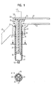
- FIGS. 1-4 of an inventive hydraulic distraction device comprises a support body 43, who carries a handle 45 on one side and on the opposite Side is connected in one piece to a tongue-shaped platform 13, which forms a lower working section of the distraction device.
- the support body 43 two parallel passages are also formed, each down into a support tube attached to the support body 43 19 pass over.
- the support body 43 On the side facing away from the support tubes 19 the support body 43 has a center between the passages Function block 47, which is discussed in more detail elsewhere becomes.
- a cylinder is inserted into the passages of the support body 43 17 one in this embodiment in the form of a commercially available Disposable syringe provided piston / cylinder arrangement.
- the cylinders 17 are each supported by tabs 59 on one appropriately trained annular shoulder 44 of the support body 43.
- the Cylinder 17 are each with their outer wall on the inner wall of the Support tube 19 at.
- Connection sections 55 are fluid lines not shown in FIGS. 1-4 screwed.
- Each disposable syringe further comprises a piston 15 with one the inner wall of the cylinder 17 in a fluid-tight piston section 16 and a piston rod 27 facing away from the piston section 16 free end in a also called a mushroom, radially opposite the piston rod 27 passes over the enlarged head section 57.
- the piston 15 is guided in the region of the piston rod 27 by a cross-shaped rib structure 31 (see cross-sectional view A-A below in Fig. 1).
- the piston rod 27 comprises four ribs, each two adjacent ribs enclose an angle of 90 °.
- piston 15 limit the ribs of the piston rod 27 chambers 29 within the cylinder 17.
- two mutually opposite chambers cf. the cross-sectional view A-A
- One reinforcing insert 21 is in one piece with another tongue-shaped Platform 11 connected to the upper working section of the invention Distraction device forms.
- the other reinforcement insert 23 is provided in the form of a separate component.
- the one with insert 21 connected to upper platform 11, separate insert 23 and the piston 15 are first assembled into a piston unit, before it is inserted as a whole into the cylinder 17, whereby the cylinder 17 previously in the corresponding passage of the Carrier 43 may have been inserted.
- the mushroom-shaped head 57 of the Piston rod 27 first with one side in a slot-shaped receptacle between the upper platform 11 and one parallel to the upper one Platform 11 extending flange portion 24 introduced, the component a transition section 49 between the upper platform 11 and the associated with this reinforcement insert 21.
- the separate reinforcement insert 23 has a corresponding one Provided flange portion 24 so that the head 57 of the piston rod 27th spatially between the two inserts 21, 23 and the upper platform 11 is fixed.
- Receiving slot When inserting the head 57 into the one formed in the transition section 49 Receiving slot reaches the one connected to the upper platform 11 Insert 21 in the corresponding chamber (see cross-sectional view A-A in Fig. 1) of the rib structure 31. The same applies when inserting the separate insert 23.
- FIG. 2 shows in particular the middle with respect to the Support tubes 19, from which the cylinders 17 each a little way down protrude, arranged handle 45. Also shown in Fig. 2 are in the direction of the handle 45 sides of the fixed the upper platform 11 connected inserts 21 and each of the two the chamber for the insert 21 delimiting ribs of the rib structure 31st
- the function block 47 is on its facing in the direction of the handle 45 Side with scales 53 on which the respective piston position can be read, providing a measure of the distraction length is available.
- the function block 47 of the transition sections 49 each encompassed in a corner area and thus serves as a guide for the piston unit and the upper one Platform 11 existing assemblies.
- the transition sections 49 each have a guide section for the relevant assembly represents a rotation of the assembly relative to the support body 43 the longitudinal axis of the piston / cylinder unit is reliably prevented and thus a constant orientation of the respective upper platform 11 ensures.
- the function block 47 have a trapezoidal shape that widens upwards, so that - unlike in FIG. 2 - the outer sides 53 are not parallel, but rather inclined to the direction of distraction.
- Guide section 49 and function block 47 One at complete inserted piston unit still little play between Guide section 49 and function block 47 is in this way increasing distraction length reduced.
- FIG. 3 in which the distraction device according to the invention without in the Cylinder 17 inserted piston units and thus without upper platforms 11 shows, in particular, that relating to the longitudinal axis tabs 59 protruding at right angles, with which the cylinders 17 each rest on the ring shoulders 44 of the supporting body 43 provided for this purpose.
- both piston / cylinder arrangements can be connected to a common, here only fluid supply device 33 shown in principle connected become.
- Switching valves 41 allow the two units to operate independently of each other in that the one unit through Close the relevant valve 41 at the distraction length just reached fixed and in the other unit by leaving the Valve 41 the distraction is continued. This can, for example when spreading a knee with an asymmetrical distribution of forces be worked.
- a pressure display device connected to the common fluid line 37 39 can be a measure of between work sections effective distraction force can be read.
- Fig. 6 shows an example in which the two piston / cylinder arrangements the distraction device completely independent of each other can be operated.
- Each unit is a separate fluid supply device 33 assigned to the respective via a single line 38 Cylinder is connected.
- Each individual line 38 is a switching valve 41 to selectively shut off or release the individual line 38 and one Pressure display device 39 assigned.
- disposable syringes 33 can be from be of the same type as that which forms the piston / cylinder arrangements 15, 17 Disposable syringes, provided that this is a total for the two piston / Cylinder assemblies 15, 17 required fluid volumes with a single one Disposable syringe can be provided. At least for that predominant part of with the aid of the distraction device according to the invention feasible operations this is because in most cases, the aim is an excessive extension anyway to avoid the piston units.
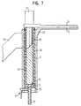
- a distraction device in the further embodiment of a distraction device according to the invention 7 and 8 is only a single reinforcement insert 25 provided, the fixed and in particular in one piece with the upper Platform 11 is formed.
- the insert 25 is a full cylinder, the with its outer wall on the inner wall one in this embodiment tubular piston rod 27 abuts so that the inside of the piston rod 27 is completely filled by the insert 25.
- the one-piece with a fluid line 37 only partially shown in FIG. 7 connected cylinder 17 of the piston / cylinder arrangement is in this Embodiment from below in the connected to the support body 43 Support tube 19 introduced.
- a locking device 77 with a fork-shaped locking section 79 serves to secure the inserted Cylinder 17. For reasons explained below the insertion of the cylinder 17 into the support tube 19 in the cylinder 17 inserted piston 15 so that to complete the distraction device then only the fully cylindrical inserts 25 in the tubular piston rods 27 need to be inserted.
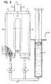
- the two piston / cylinder arrangements are components a closed hydraulic system that is also a common one Fluid supply device 33 in the form of a disposable syringe 35 Hydraulic fluid 36, in particular water, and one of the two cylinders fluid line 37 connecting the syringe 33 with switching valves 41 each in the form of a shut-off valve.
- the fluid line 37 provided with one or more pressure indicators his.
- This hydraulic system is assembled and in particular ready unit already filled with the hydraulic fluid 36 and delivered sterilized as a whole.
- the handling of the distraction device according to the invention is thereby extremely easy for the surgeon. If necessary after sterilization of the non-hydraulic system, i.e. the rest, not to the components of the hydraulic system mentioned above Distraction device, only need the two piston / cylinder arrangements of the sterile hydraulic system from below into the support tubes 19 inserted and secured by means of the locking devices 77 and the reinforcement inserts 25 with the upper tongues 11 from above to be used.
- the distraction device according to the invention can also only a single piston / cylinder assembly 15, 17 with a single pair include tongue-shaped platforms 11, 13.
- the components of the piston / cylinder arrangements are preferably around plastic parts produced by injection molding, whereas at least the support tubes 19 and the reinforcement inserts 21, 23, 25 made of a material with higher bending stiffness, for example made of metal or a fiber-reinforced plastic, which are because of their reuse in the hospital, for example, steam sterilization to let.
- the distraction devices described in FIGS. 1 to 8 serve for spreading the knee as explained in the introductory part, and allow the so-called “swinging out” of the knee joint for determination the optimum determined by the natural tension of the ligaments Distance between femur and tibia while displaying characteristic values for the current knee for the knee in question Distraction length and distraction force parameters.
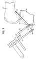
- FIGS. 9 to 11 show the use of distraction devices according to the invention when implanting an anterior cruciate ligament.
- the band 65 is formed in a previously formed femur 61 Bore inserted and there by means of along the surface line of the band 65 screwed, not shown displacement screw set.
- the tape is then passed through a previously in the tibia 63 trained bore pulled forward to this tibial bore fixed by means of a further displacement screw, not shown to become.
- the distraction device is with its top Working platform 11, which - as shown in Fig. 9 - for this purpose with a special Attachment 81, the front free end of an angled or angled support and / or fastening section is formed can be supported on the tibia 63.
- the band 65 and possibly - how 9-11 - a tension element connected to the band 65 73 for example in the form of a wire is through in both platforms 11, 13 trained recesses 69 pulled through and on the lower Platform 13 attached.
- the cutouts 69 are dimensioned such that that a screwdriver 71 shown schematically in FIG fitted displacement screw along the band 65 are introduced can around the right bias tape 65 in the Fix tibia 63.
- the distraction device Way possible before final fixing of the band 65 in Tibia 63 either in all possible or at least in some selected positions, i.e. Diffraction angles, the knee's ligament tension to measure or determine a measure of the belt tension, in order to adjust a belt tension by varying the belt length, for all possible diffraction angles and thus for normal movement of the knee joint is suitable.
- the measure of the belt tension is determined with a pressure display device, such as, for example in connection with the embodiments of FIGS. 1-8 was while the measure of the band length by the distraction length given on a display device, e.g. in form of a Scale, can be read, such as in connection, for example was described with the embodiments of FIGS. 1-8.
- the upper platform 11 for example, with the help of bone nails can be attached to the tibia 63 in order for defined geometric Conditions.
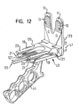
- FIGS. 12 to 24 corresponds to a distraction device according to the invention with regard to the principle of reinforcement of those not shown here Piston / cylinder arrangements as well as with regard to other aspects, which result from the description below, basically the 1 to 4 described first embodiment.
- the two upper working sections or tongues 11 (cf. in particular Fig. 12 - 15 and 23 and 24) are fixed in the region of their rear end connected to a rear reinforcement insert 21.
- Separate reinforcement inserts 23 serve to complete the piston reinforcement accordingly the first embodiment (Fig. 1).
- the piston and cylinder of the piston / cylinder assemblies that are each again formed by a commercially available disposable syringe, not shown. 13, however, is the free space 153 for the piston including the area for the head section or Mushroom of the piston between the flange portions 24 of the reinforcement inserts 21, 23 to recognize.
- the piston is in the assembled state of the distraction device including the reinforcement inserts 21, 23 in the cylinder of the inserted piston / cylinder arrangement, which in turn in a relevant support receptacle 19 is introduced on a central support body 43 is formed, which will be described in more detail below.
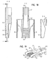
- the Support receptacles 19 are each partially tubular and in shape a support tube cut obliquely from below is provided (FIG. 19). The cut-away area faces forward, i.e. towards the free ends of the working tongues 11, 13, so that in the opposite Direction, i.e. to the rear, a support along the entire length of the Support shots 19 is given.
- the support receptacles 19 are each with a slot-shaped insertion opening 121 provided, which extend from the upper insertion opening into the upper area of the lower one, which is oblique due to the cutting Opening of the support receptacle 19 extends.
- the lateral insertion openings 121 advantageously allow when assembling the distraction device with the cylinder fluid line connected below from above into the respective support holder 19 by simply inserting the fluid line laterally over the Insert opening 121 is inserted.
- the fluid line can thus always be fixed remain connected to the cylinder, but it is not - as in the embodiment of Fig. 7 - is required, the cylinder of insert below and provide a locking device.
- the lower worktop with an approximately Y-shaped outline, the Legs formed by the two lower working tongues 13 is over its rear end in a slot 149 formed on the support body 43 (Fig. 19) attached.
- the support body 43 also has a parallel to the distraction axis extending, continuous adjustment channel 127, which between the passes through two support seats 19.
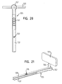
- the adjustment channel 127 serves a platform 123 for receiving a support rod 125 having carrier, the following in connection with FIGS. 20 to 22 is described in more detail.
- a reading window 143 for the adjustment channel 127 formed, through which the back of the in the adjustment channel 127 inserted support rod 125 visible and one on this Rear attached scale 141 (Fig. 20) can be read.
- a handle 45 the distraction device is below the reading window 143 with the Rear wall of the support body 43 connected.
- the adjustment channel 127 and the support rod 125 are with profiles 129, 131, 133, 135 provided in the form of rib structures, to the following is discussed in more detail.
- the Function block 147 is an integral part of the central supporting body 43rd
- Function block 47 serves, among other things. to guide the upper working tongues 11. Furthermore, a pivot head 157 of the support rod are in the function block 47 125 and one extending perpendicular to the support rod 125 Connector 155 added (Fig. 15), through which the platform 123 is connected to the support rod 125.
- the platform 123 is arranged directly in front of the function block 47.
- the width of the platform 123 is slightly less than the total width of the upper working section 11, while the depth of the platform 123 is such is dimensioned that - seen from the function block 47 - the platform ends before the lower work section enters the two reeds 13 shares.
- the platform 123 is located for spreading the knee between the femur and tibia inserted working sections 11, 13 outside the projection of the tibia along the distraction axis.
- 16 to 19 are in particular the arrangement and configuration the profiles 129 cooperating with the support rod 125, 131, which are formed on the inside of the adjustment channel 127 are.
- a profile 129 in the form of extending transversely to the distraction axis Ribs or webs in the lower area of the adjustment channel 127 are formed, used to fix the support rod 125 in different Altitudes.
- the adjustment channel is 127 based on the height level of the upper insertion openings of the support receptacles 19 extended downwards such that the width of the Adjustment channel 127 increases steadily.
- the transverse profile 129 is formed in the lower area of this extension of the adjustment channel 127, which has the shape of a slim cross section Has trapezes.
- Adjustment channel 127 On the opposite inner wall (Fig. 18, left representation) is the Adjustment channel 127 with a longitudinal profile 131 in the form of parallel ribs extending to the distraction axis (FIG. 17).
- This Profileing 131 serves the support rod 125 in different Fix oblique positions, which is discussed in more detail below becomes.
- the support rod 125 in some areas as a fork is formed with two fork arms 137, 139.
- the distance between the fork arms 137, 139 from each other is the distance between the profiles 129, 131 provided inside of the adjustment channel 127 of the support body 43 tuned, the one introduced into the adjustment channel 127
- the profiling 133 of the Support rod 125 is provided in the form of longitudinal ribs
- the Profiling formed on the opposite side 135 transverse ribs 22, which - as the detail A shows in the upper right in FIG. 22 - has a sawtooth shape have such that movements of the support rod 125 from the adjustment channel 127 out without compressing the fork arms 137, 139 are possible, movements of the support rod 125 down in blocking the adjustment channel 127 into it, however, and only when compressed Fork arms 137, 139 are possible.
- the support rod act 125 and the adjustment channel 127 due to their profiles 135, 129 with regard to movements parallel to the distraction axis in the manner of a Ratchet up.
- the diameter of the upper part which has a partially circular outer shape Swivel head 157 of the support rod 125, with which the platform 123 connected via the connector 155 corresponds to the constant Width of the adjustment channel 127 above the extension.
- the support rod 125 can move around that guided in the adjustment channel 127 Swivel head 157 in that of the central axes of the two tubular parts Support shots 19 pivoted level, the Swivel axis through which the platform 123 with the swivel head 157 connecting connector 155 passes through, which is in a Recess 159 of the functional block 47 can rotate (FIGS. 16, 18, 19). Movements of the swivel head included in function block 47 157 across the distraction axis are not possible.
- the pivoting of the support rod 125 in the adjustment channel 127 has a tilt platform 123 from a neutral position perpendicular to the distraction axis out to consequence.
- the longitudinal profiles 131, 133 enable fixing the support rod 125 in from a parallel orientation state deflected to the distraction axis, i.e. an inclination of the Platform 123 can be fixed by means of profiles 131, 133.
- the Profiles 133, 135 formed on the support rod 125, in particular the transverse profiling 135 are so deep and in their width or Dimension the length so that the support rod 125 engages despite the inclined position.
- the support body 43 is in its lower region with a not shown Provide display device in the form of a scale on which a Measure for a respective pivot position of the support rod 125 and thus for the relevant inclination of the platform 123 can be read.
- FIG. 23 and 24 show the upper working tongues 11 and the reinforcing inserts 21, 23. Also shown are tabs projecting inwards 147, the rear sides perpendicular to that formed by the tongues 11 Platform run. As shown in Fig. 14, the is for the surgeon during the back of the operation visible with the right tongue connected tab 147 (FIG. 24) with the previously mentioned scale 145 provided, via which the height of the upper work platform 11 in Reference to the support body 43 can be read.
Landscapes
- Health & Medical Sciences (AREA)
- Life Sciences & Earth Sciences (AREA)
- Surgery (AREA)
- Molecular Biology (AREA)
- General Health & Medical Sciences (AREA)
- Biomedical Technology (AREA)
- Heart & Thoracic Surgery (AREA)
- Medical Informatics (AREA)
- Nuclear Medicine, Radiotherapy & Molecular Imaging (AREA)
- Animal Behavior & Ethology (AREA)
- Engineering & Computer Science (AREA)
- Public Health (AREA)
- Veterinary Medicine (AREA)
- Dentistry (AREA)
- Oral & Maxillofacial Surgery (AREA)
- Orthopedic Medicine & Surgery (AREA)
- Prostheses (AREA)
- Surgical Instruments (AREA)
Abstract
Description
- Fig. 1
- einen Längsschnitt durch eine Distraktionsvorrichtung gemäß einer Ausführungsform der Erfindung,
- Fig. 2
- eine Vorderansicht der Distraktionsvorrichtung von Fig. 1,
- Fig. 3
- eine Draufsicht auf die Distraktionsvorrichtung von Fig. 1 ohne Zylinder und ohne obere Arbeitsabschnitte,
- Fig. 4
- eine Draufsicht entsprechend Fig. 3 mit eingeführten Zylindern und oberen Arbeitsabschnitten,
- Fig. 5
- eine Möglichkeit für den Anschluss einer erfindungsgemäßen Distraktionsvorrichtung an eine Fluidzuführeinrichtung,
- Fig. 6
- eine Möglichkeit für den Anschluss einer erfindungsgemäßen Distraktionsvorrichtung an zwei unabhängig voneinander betreibbare Fluidzuführeinrichtungen,
- Fig. 7
- einen Teillängsschnitt durch eine Distraktionsvorrichtung gemäß einer weiteren Ausführungsform der Erfindung,
- Fig. 8
- die Distraktionsvorrichtung von Fig. 7 als Bestandteil eines geschlossenen Hydrauliksystems,
- Fig. 9 - 11
- die Verwendung erfindungsgemäßer Distraktionsvorrichtungen bei der Implantation eines vorderen Kreuzbandes,
- Fig. 12
- eine perspektivische Ansicht einer Distraktionsvorrichtung gemäß einer weiteren Ausführungsform der Erfindung,
- Fig. 13 - 15
- verschiedene Ansichten der Distraktionsvorrichtung von Fig. 12,
- Fig. 16 - 19
- verschiedene Ansichten eines Tragkörpers der Distraktionsvorrichtung von Fig. 12,
- Fig. 20 und 21
- verschiedene Ansichten eines Trägers der Distraktionsvorrichtung von Fig. 12,
- Fig. 22
- verschiedene Ansichten einer Tragstange des Trägers der Fig. 20 und 21, und
- Fig. 23 und 24
- jeweils eine perspektivische Ansicht eines linken bzw. rechten oberen Arbeitsabschnittes mit zugehörigen Verstärkungseinsätzen.
- 11
- oberer Arbeitsabschnitt, obere Zunge
- 13
- unterer Arbeitsabschnitt, untere Zunge
- 15
- Kolben
- 16
- Kolbenabschnitt
- 17
- Zylinder
- 19
- Stützaufnahme, Stützrohr
- 21
- Verstärkungseinsatz
- 23
- Verstärkungseinsatz
- 24
- Flanschabschnitt
- 25
- Verstärkungseinsatz
- 27
- Kolbenstange
- 29
- Kammer
- 31
- Rippenstruktur
- 33
- Fluidzuführeinrichtung
- 35
- Spritze
- 36
- Hydraulikfluid
- 37
- Fluidleitung
- 39
- Druckanzeigeeinrichtung
- 41
- Schaltventil
- 43
- Tragkörper
- 44
- Ringschulter
- 45
- Handgriff
- 47
- Funktionsblock
- 49
- Führungsabschnitt
- 51
- Anschlagfläche
- 53
- Anzeigeeinrichtung, Skala
- 55
- Anschlussabschnitt
- 57
- Kopfabschnitt, Pilz
- 59
- Lasche
- 61
- Femur
- 63
- Tibia
- 65
- Kreuzband
- 67
- Abstütz- und/oder Befestigungsabschnitt
- 69
- Aussparung
- 71
- Fixierwerkzeug, Schraubendreher
- 73
- Zugelement
- 77
- Verriegelungseinrichtung
- 79
- gabelförmiger Verriegelungsabschnitt
- 81
- Aufsatz
- 121
- Einlegeöffnung
- 123
- Plattform
- 125
- Tragstange
- 127
- Verstellkanal
- 129
- Profilierung
- 131
- Profilierung
- 133
- Profilierung
- 135
- Profilierung
- 137
- Gabelarm
- 139
- Gabelarm
- 141
- Anzeigeeinrichtung, Skala
- 143
- Ablesefenster
- 145
- Anzeigeeinrichtung, Skala
- 147
- Lasche
- 149
- Schlitz
- 151
- Aussparung
- 153
- Freiraum für Kolben
- 155
- Verbindungsstück
- 157
- Schwenkkopf
- 159
- Aussparung für Verbindungsstück
Claims (47)
- Hydraulische Distraktionsvorrichtung für Operationen, insbesondere für Knieoperationen, mit wenigstens einem Paar relativ zueinander verstellbarer Arbeitsabschnitte (11, 13) und zumindest einer auswechselbaren Kolben-/Zylinder-Anordnung (15, 17) aus Kunststoff, deren Kolben (15) mit dem einen Arbeitsabschnitt (11) und deren Zylinder (17) mit dem anderen Arbeitsabschnitt (13) lösbar gekoppelt und die durch eine äußere, den Zylinder (17) von außen abstützende Stützaufnahme (19) sowie durch wenigstens einen inneren, zusammen mit dem Kolben (15) in den Zylinder (17) einführbaren Verstärkungseinsatz (21, 23, 25) versteift ist.
- Distraktionsvorrichtung nach Anspruch 1,
dadurch gekennzeichnet, dass der Kolben (15) und der Zylinder jeweils im Spritzgussverfahren hergestellte Einwegartikel sind. - Distraktionsvorrichtung nach Anspruch 1 oder 2,
dadurch gekennzeichnet, dass der Kolben (15) und der Verstärkungseinsatz (21, 23, 25) im zusammengesetzten Zustand eine kompakte Kolbeneinheit bilden, die zumindest über einen Teilumfangsbereich das Innere des Zylinders (17) vollständig ausfüllt. - Distraktionsvorrichtung nach einem der vorhergehenden Ansprüche,
dadurch gekennzeichnet , dass die Kolben-/Zylinder-Anordnung (15, 17) von einer handelsüblichen Einwegspritze gebildet ist. - Distraktionsvorrichtung nach einem der vorhergehenden Ansprüche,
dadurch gekennzeichnet , dass ein zwischen der Innenwand des Zylinders (17) und einer Kolbenstange (27) vorhandener Freiraum durch den Verstärkungseinsatz (21, 23) zumindest teilweise ausgefüllt ist. - Distraktionsvorrichtung nach einem der vorhergehenden Ansprüche,
dadurch gekennzeichnet , dass wenigstens eine im Zylinder (17) vorhandene Kammer (29), die durch eine bis an die Innenwand des Zylinders (17) reichende, insbesondere im Querschnitt kreuz- oder X-förmige Rippenstruktur (31) einer Kolbenstange (27) begrenzt ist, durch den Verstärkungseinsatz (21, 23) zumindest teilweise ausgefüllt ist. - Distraktionsvorrichtung nach Anspruch 6,
dadurch gekennzeichnet , dass wenigstens ein Paar einander gegenüberliegender Kammern jeweils durch einen Verstärkungseinsatz (21, 23) zumindest teilweise ausgefüllt ist. - Distraktionsvorrichtung nach einem der Ansprüche 1 bis 5,
dadurch gekennzeichnet , dass der Verstärkungseinsatz (25) das Innere einer rohrförmigen, an der Innenwand des Zylinders (17) geführten Kolbenstange (27) zumindest über einen Teilumfangsbereich vollständig ausfüllt. - Distraktionsvorrichtung nach einem der vorhergehenden Ansprüche,
dadurch gekennzeichnet , dass die Kolben-/Zylinder-Anordnung (15, 17) im zusammengesetzten Zustand mit den Arbeitsabschnitten (11, 13) koppelbar ist. - Distraktionsvorrichtung nach einem der vorhergehenden Ansprüche,
dadurch gekennzeichnet , dass wenigstens ein Verstärkungseinsatz (21, 25) fest mit dem einen Arbeitsabschnitt (11) verbunden ist. - Distraktionsvorrichtung nach einem der vorhergehenden Ansprüche,
dadurch gekennzeichnet , dass wenigstens ein Verstärkungseinsatz (23) in Form eines separaten Bauteils vorgesehen ist. - Distraktionsvorrichtung nach einem der vorhergehenden Ansprüche,
dadurch gekennzeichnet , dass die Stützaufnahme (19) für den Zylinder (17) und der mit dem Zylinder (17) koppelbare Arbeitsabschnitt (13) fest mit einem Tragkörper (43) verbunden sind. - Distraktionsvorrichtung nach einem der vorhergehenden Ansprüche,
dadurch gekennzeichnet , dass auf der den Arbeitsabschnitten (11, 13) gegenüberliegenden Seite der Kolben-/Zylinder-Anordnung (15, 17) ein Handgriff (45) vorgesehen ist, der bevorzugt fest mit einem Tragkörper (43) verbunden ist. - Distraktionsvorrichtung nach einem der vorhergehenden Ansprüche,
dadurch gekennzeichnet , dass der mit dem Zylinder (17) koppelbare Arbeitsabschnitt (13) fest mit einem sich parallel zur Distraktionsrichtung erstreckenden Funktionsblock (47) verbunden ist, der als Verdreh- und/oder Auslenksicherung für den mit dem Kolben (15) koppelbaren Arbeitsabschnitt (11) ausgebildet ist. - Distraktionsvorrichtung nach Anspruch 14,
dadurch gekennzeichnet , dass der Funktionsblock (47) einen von einer Kreisform abweichenden Außenquerschnitt aufweist und zumindest über einen Teilumfangsbereich von einem Führungsabschnitt (49) des Arbeitsabschnitts (11) verdrehsichernd umgriffen ist. - Distraktionsvorrichtung nach Anspruch 14 oder 15,
dadurch gekennzeichnet , dass der Funktionsblock (47) eine geringfügig gegenüber der Distraktionsrichtung geneigte, in Richtung zunehmender Distraktionslänge auf die Längsachse der Kolben-/Zylinder-Anordnung (15, 17) zu laufende Anschlagfläche (51) aufweist, die mit dem Arbeitsabschnitt (11) auslenkungssichernd zusammenwirkt. - Distraktionsvorrichtung nach einem der Ansprüche 14 bis 16,
dadurch gekennzeichnet, dass der Funktionsblock (47) mit einer Anzeigeeinrichtung (53), insbesondere in Form einer an einer Außenseite angebrachten Skala, versehen ist, an der ein Maß für die Distraktionslänge ablesbar ist. - Distraktionsvorrichtung nach einem der vorhergehenden Ansprüche,
dadurch gekennzeichnet, dass die Stützaufnahme (19) und/oder der Verstärkungseinsatz (21, 23, 25) aus einem Material mit einer höheren Biegesteifigkeit als der Kunststoff der Kolben-/Zylinder-Anordnung (15, 17) hergestellt sind, insbesondere aus Metall oder einem faserverstärkten Kunststoff. - Distraktionsvorrichtung nach einem der vorhergehenden Ansprüche,
dadurch gekennzeichnet, dass die Kolben-/Zylinder-Anordnung (15, 17) mit einer Anzeigeeinrichtung, insbesondere in Form einer am Zylinder angebrachten Skala, versehen ist. - Distraktionsvorrichtung nach einem der vorhergehenden Ansprüche,
dadurch gekennzeichnet, dass eine Fluidzuführeinrichtung (33) für die Kolben-/Zylinder-Anordnung (15, 17) eine von Hand betätigbare Spritze (35) umfasst, insbesondere eine Einwegspritze. - Distraktionsvorrichtung nach einem der vorhergehenden Ansprüche,
dadurch gekennzeichnet, dass an eine die Kolben-/Zylinder-Anordnung (15, 17) mit einer Fluidzuführeinrichtung (33) verbindende Fluidleitung (37) wenigstens eine Druckanzeigeeinrichtung (39) angeschlossen ist. - Distraktionsvorrichtung nach einem der vorhergehenden Ansprüche,
dadurch gekennzeichnet, dass die Kolben-/Zylinder-Anordnung (15, 17) ein Bestandteil eines geschlossenen, als eine Einheit handhabbaren, insbesondere sterilisierbaren, Hydrauliksystems ist, das zusätzlich zumindest eine Fluidzuführeinrichtung (33), eine die Kolben-/Zylinder-Anordnung (15, 17) mit der Fluidzuführeinrichtung (33) verbindende Fluidleitung (37) sowie ein Hydraulikfluid, insbesondere Wasser, umfasst und als Ganzes mit den Arbeitsabschnitten (11, 13) koppelbar ist. - Distraktionsvorrichtung nach einem der vorhergehenden Ansprüche,
dadurch gekennzeichnet, dass wenigstens zwei im mit den Arbeitsabschnitten (11, 13) gekoppelten Zustand in parallelen Richtungen wirksame Kolben-/Zylinder-Anordnungen (15, 17) vorgesehen sind. - Distraktionsvorrichtung nach Anspruch 23,
dadurch gekennzeichnet , dass die Kolben-/Zylinder-Anordnungen (15, 17) während der Benutzung an eine gemeinsame Fluidzuführeinrichtung (33) angeschlossen sind. - Distraktionsvorrichtung nach Anspruch 23 oder 24,
dadurch gekennzeichnet , dass durch in einer die Kolben-/Zylinder-Anordnungen (15, 17) mit einer Fluidzuführeinrichtung (33) verbindenden Fluidleitung (37) angeordnete Schaltventile (41) die Kolben-/ Zylinder-Anordnungen (15, 17) unabhängig voneinander jeweils wahlweise mit der Fluidzufuhr verbindbar oder von der Fluidzufuhr trennbar sind. - Distraktionsvorrichtung nach einem der vorhergehenden Ansprüche,
dadurch gekennzeichnet , dass zum Einstellen von Sollabständen zwischen Femur (61) und Tibia (63) die Arbeitsabschnitte (11, 13) einen zwischen Femur (61) und Tibia (63) einbringbaren und sich im Wesentlichen senkrecht zur Distraktionsrichtung erstreckenden Aufspreizabschnitt bilden. - Distraktionsvorrichtung nach einem der vorhergehenden Ansprüche,
dadurch gekennzeichnet , dass zur Bestimmung der Bandspannung und/oder Bandlänge bei der Implantation von vorderen Kreuzbändern (65) ein oberer Arbeitsabschnitt (11) mit einem Abstütz- und/oder Befestigungsabschnitt (67, 81) versehen ist, über den die Vorrichtung an der Tibia (63) abstützbar und/oder befestigbar ist. - Distraktionsvorrichtung nach Anspruch 27,
dadurch gekennzeichnet , dass die Arbeitsabschnitte (11, 13) jeweils mit wenigstens einer Aussparung (69) zum Hindurchführen eines Fixierwerkzeugs (71) und eines Fixierelementes zum Fixieren des Bandes (65) in der Tibia (63) versehen sind. - Distraktionsvorrichtung nach Anspruch 27 oder 28,
dadurch gekennzeichnet, dass der obere Arbeitsabschnitt (11) mit wenigstens einer Aussparung (69) zum Hindurchführen des Bandes (65) und/oder eines mit dem Band (65) verbundenen Zugelementes (73) versehen ist. - Distraktionsvorrichtung nach einem der Ansprüche 27 bis 29,
dadurch gekennzeichnet, dass ein unterer Arbeitsabschnitt (13) mit wenigstens einem Befestigungsabschnitt zum Befestigen des Bandes (65) oder eines mit dem Band (65) verbundenen Zugelementes (73) versehen ist. - Distraktionsvorrichtung nach einem der vorhergehenden Ansprüche,
dadurch gekennzeichnet , dass die Arbeitsabschnitte (11, 13) jeweils als zungenförmige Plattformen ausgebildet sind, die im zusammengesetzten Zustand zumindest im Wesentlichen parallel zueinander verlaufen. - Distraktionsvorrichtung nach einem der vorhergehenden Ansprüche,
dadurch gekennzeichnet , dass die Stützaufnahme (19) für den Zylinder zumindest teilrohrförmig ausgebildet und der Zylinder längs der Rohrachse in die Stützaufnahme (19) einführbar ist, wobei die Stützaufnahme (19) zum seitlichen Einlegen einer mit dem Zylinder verbundenen Fluidleitung eine insbesondere schlitzförmige Einlegeöffnung (121) aufweist. - Distraktionsvorrichtung nach einem der vorhergehenden Ansprüche,
dadurch gekennzeichnet , dass ein Träger (123, 125) für eine Schnittlehre, insbesondere einen Schnittblock, vorgesehen ist, der mit einem Tragkörper (43) koppelbar ist, mit dem die Stützaufnahme (19) für den Zylinder und der mit dem Zylinder koppelbare Arbeitsabschnitt (13) verbunden sind. - Distraktionsvorrichtung nach Anspruch 33,
dadurch gekennzeichnet , dass der Träger eine als Auflage für die Schnittlehre dienende Plattform (123) und eine mit dem Tragkörper (43) koppelbare Tragstange (125) umfasst, die an ihrem einen Ende die Plattform (123) trägt und in einen Verstellkanal (127) des Tragkörpers (43) einführbar ist, in welchem die Tragstange (125) relativ zum Tragkörper (43) verstellbar und in einer Vielzahl von insbesondere diskret verteilten Positionen am Tragkörper (43) fixierbar ist. - Distraktionsvorrichtung nach Anspruch 34,
dadurch gekennzeichnet , dass die Tragstange (125) und die Innenwand des Verstellkanals (127) mit zur Fixierung ihrer Relativlage zusammenwirkenden, insbesondere rippenförmigen Profilierungen (129, 131, 133, 135) versehen sind. - Distraktionsvorrichtung nach Anspruch 34 oder 35,
dadurch gekennzeichnet , dass die Verstellanordnung aus Tragstange (125) und Verstellkanal (127) selbsthemmend ausgebildet ist. - Distraktionsvorrichtung nach einem der Ansprüche 34 bis 36,
dadurch gekennzeichnet , dass die Tragstange (125) zumindest bereichsweise gabelförmig ausgebildet ist und gegen eine Rückstellkraft zusammendrückbare Gabelarme (137, 139) umfasst, die insbesondere auf ihren einander abgewandten Außenseiten mit Profilierungen (133, 135) versehen sind. - Distraktionsvorrichtung nach Anspruch 37,
dadurch gekennzeichnet , dass die Gabelarme (137, 139) der Tragstange (125) insbesondere an in entgegengesetzte Richtungen weisenden Seiten mit Profilierungen in Form von unterschiedlich orientierten Rippenstrukturen (133, 135) versehen sind. - Distraktionsvorrichtung nach einem der Ansprüche 34 bis 38,
dadurch gekennzeichnet , dass die Tragstange (125) insbesondere zur Höhenverstellung der Schnittlehre zumindest längs der Distraktionsachse relativ zum Tragkörper (43) verstellbar ist. - Distraktionsvorrichtung nach einem der Ansprüche 34 bis 39,
dadurch gekennzeichnet , dass die Tragstange (125) und der Tragkörper (43) zumindest bei Verstellbewegungen längs der Distraktionsachse nach Art einer Ratsche zusammenwirken. - Distraktionsvorrichtung nach einem der Ansprüche 34 bis 40,
dadurch gekennzeichnet , dass die Tragstange (125) aus einer parallelen Ausrichtung zur Distraktionsachse heraus gegenüber dem Tragkörper (43) verschwenkbar ist, insbesondere in einer von zwei zu beiden Seiten des Verstellkanals (127) angeordneten Kolben-/Zylinder-Anordnungen festgelegten Ebene. - Distraktionsvorrichtung nach Anspruch 41,
dadurch gekennzeichnet , dass die Tragstange (125) einen auf die Breite des Verstellkanals (127) abgestimmten Schwenkkopf (157) aufweist, um welchen die Tragstange (125) verschwenkbar ist. - Distraktionsvorrichtung nach einem der Ansprüche 34 bis 42,
dadurch gekennzeichnet , dass sich der Verstellkanal (127) in bei eingesteckter Tragstange (125) von der Plattform (123) weg weisender Richtung erweitert. - Distraktionsvorrichtung nach einem der Ansprüche 34 bis 43,
dadurch gekennzeichnet, dass die Tragstange (125) mit einer Anzeigeeinrichtung (141), insbesondere in Form einer Skala, versehen ist, die im in den Verstellkanal (127) eingeführten Zustand über ein in einer Wand des Tragkörpers (43) ausgebildetes Ablesefenster (143) von außen sichtbar ist. - Distraktionsvorrichtung nach einem der Ansprüche 34 bis 44,
dadurch gekennzeichnet , dass die Plattform (123) bei zum Aufspreizen des Knies zwischen Femur und Tibia eingebrachten Arbeitsabschnitten (11, 13) zumindest im Wesentlichen außerhalb der Projektion der Tibia längs der Distraktionsachse gelegen ist. - Distraktionsvorrichtung nach einem der Ansprüche 34 bis 45,
dadurch gekennzeichnet, dass die Plattform (123) vor einem Funktionsblock (47) gelegen ist, der sich parallel zur Distraktionsachse erstreckt und mit dem der mit dem Zylinder koppelbare Arbeitsabschnitt (13) fest verbunden ist. - Distraktionsvorrichtung nach einem der Ansprüche 32 bis 46,
dadurch gekennzeichnet, dass der obere Arbeitsabschnitt (11) mit einer Anzeigeeinrichtung (145), insbesondere in Form einer Skala, versehen ist.
Priority Applications (1)
| Application Number | Priority Date | Filing Date | Title |
|---|---|---|---|
| EP20040010112 EP1475044B1 (de) | 2003-05-06 | 2004-04-28 | Distraktionsvorrichtung |
Applications Claiming Priority (5)
| Application Number | Priority Date | Filing Date | Title |
|---|---|---|---|
| EP03010177 | 2003-05-06 | ||
| EP03010177A EP1475043A1 (de) | 2003-05-06 | 2003-05-06 | Distraktionsvorrichtung |
| DE10360433 | 2003-12-22 | ||
| DE10360433 | 2003-12-22 | ||
| EP20040010112 EP1475044B1 (de) | 2003-05-06 | 2004-04-28 | Distraktionsvorrichtung |
Publications (2)
| Publication Number | Publication Date |
|---|---|
| EP1475044A1 true EP1475044A1 (de) | 2004-11-10 |
| EP1475044B1 EP1475044B1 (de) | 2007-08-15 |
Family
ID=32995259
Family Applications (1)
| Application Number | Title | Priority Date | Filing Date |
|---|---|---|---|
| EP20040010112 Expired - Lifetime EP1475044B1 (de) | 2003-05-06 | 2004-04-28 | Distraktionsvorrichtung |
Country Status (1)
| Country | Link |
|---|---|
| EP (1) | EP1475044B1 (de) |
Citations (2)
| Publication number | Priority date | Publication date | Assignee | Title |
|---|---|---|---|---|
| US4501266A (en) * | 1983-03-04 | 1985-02-26 | Biomet, Inc. | Knee distraction device |
| US6482209B1 (en) * | 2001-06-14 | 2002-11-19 | Gerard A. Engh | Apparatus and method for sculpting the surface of a joint |
-
2004
- 2004-04-28 EP EP20040010112 patent/EP1475044B1/de not_active Expired - Lifetime
Patent Citations (2)
| Publication number | Priority date | Publication date | Assignee | Title |
|---|---|---|---|---|
| US4501266A (en) * | 1983-03-04 | 1985-02-26 | Biomet, Inc. | Knee distraction device |
| US6482209B1 (en) * | 2001-06-14 | 2002-11-19 | Gerard A. Engh | Apparatus and method for sculpting the surface of a joint |
Also Published As
| Publication number | Publication date |
|---|---|
| EP1475044B1 (de) | 2007-08-15 |
Similar Documents
| Publication | Publication Date | Title |
|---|---|---|
| EP0913132B1 (de) | Kniegelenkprothese | |
| DE68915981T2 (de) | Moduläre Knieprothese. | |
| DE60212852T2 (de) | Tibiale resektionsführung | |
| DE69924574T2 (de) | Bauelemente und Werkzeuge zur intramedullären Revisionschirurgie der Tibia | |
| DE69409206T2 (de) | Orthopädische Schneideführungen mit einschiebbaren Sägemesserschlitzen | |
| DE68922620T2 (de) | Chirurgisches instrument. | |
| DE102007028087B4 (de) | Modularer Implantatteil und Kniegelenkprothese | |
| EP0928172B1 (de) | Stiellose kniegelenkendoprothese | |
| DE69934060T2 (de) | Femoraler Schaftbausatz für eine modulare Knieprothese | |
| DE69630884T2 (de) | Führungsinstrument zum schneiden | |
| EP1099430B1 (de) | Knieprothesensystem | |
| DE3688207T2 (de) | Chirurgische Instrumente. | |
| EP2596757B1 (de) | Vorrichtung für die Vorgabe einer Schnittebene für die Knochenresektion | |
| DE102007032150B4 (de) | Künstliches Meniskusteil und Kniegelenkprothese | |
| EP1470787B1 (de) | Vorrichtung zur Vorbereitung einer Femurkondyle | |
| DE60108097T2 (de) | Spanngerät zum ausführen einer knieersatzoperation | |
| DE602005003462T2 (de) | Hilfsanordnung zur implantation von knieprothesen | |
| DE9190125U1 (de) | Modulares Probe-Hüftersatzsystem | |
| EP1786369A1 (de) | Chirurgisches instrument | |
| DE4038037A1 (de) | Kniegelenkendoprothese | |
| DE102010013258A1 (de) | Vorrichtung zur Positionierung von Schnittführungselementen | |
| EP1309296B1 (de) | Vorrichtung zur optimierung einer knie-endoprothese | |
| EP1475044A1 (de) | Distraktionsvorrichtung | |
| EP1475043A1 (de) | Distraktionsvorrichtung | |
| EP1108403B1 (de) | Bausatz für eine Kniegelenkprothese |
Legal Events
| Date | Code | Title | Description |
|---|---|---|---|
| PUAI | Public reference made under article 153(3) epc to a published international application that has entered the european phase |
Free format text: ORIGINAL CODE: 0009012 |
|
| 17P | Request for examination filed |
Effective date: 20040512 |
|
| AK | Designated contracting states |
Kind code of ref document: A1 Designated state(s): AT BE BG CH CY CZ DE DK EE ES FI FR GB GR HU IE IT LI LU MC NL PL PT RO SE SI SK TR |
|
| AX | Request for extension of the european patent |
Extension state: AL HR LT LV MK |
|
| AKX | Designation fees paid |
Designated state(s): AT BE BG CH CY CZ DE DK EE ES FI FR GB GR HU IE IT LI LU MC NL PL PT RO SE SI SK TR |
|
| RAP1 | Party data changed (applicant data changed or rights of an application transferred) |
Owner name: ZIMMER GMBH |
|
| GRAP | Despatch of communication of intention to grant a patent |
Free format text: ORIGINAL CODE: EPIDOSNIGR1 |
|
| GRAS | Grant fee paid |
Free format text: ORIGINAL CODE: EPIDOSNIGR3 |
|
| GRAA | (expected) grant |
Free format text: ORIGINAL CODE: 0009210 |
|
| AK | Designated contracting states |
Kind code of ref document: B1 Designated state(s): AT BE BG CH CY CZ DE DK EE ES FI FR GB GR HU IE IT LI LU MC NL PL PT RO SE SI SK TR |
|
| REG | Reference to a national code |
Ref country code: GB Ref legal event code: FG4D Free format text: NOT ENGLISH |
|
| REG | Reference to a national code |
Ref country code: SE Ref legal event code: TRGR |
|
| REG | Reference to a national code |
Ref country code: CH Ref legal event code: EP |
|
| REG | Reference to a national code |
Ref country code: IE Ref legal event code: FG4D Free format text: LANGUAGE OF EP DOCUMENT: GERMAN |
|
| REF | Corresponds to: |
Ref document number: 502004004614 Country of ref document: DE Date of ref document: 20070927 Kind code of ref document: P |
|
| GBT | Gb: translation of ep patent filed (gb section 77(6)(a)/1977) |
Effective date: 20071001 |
|
| PG25 | Lapsed in a contracting state [announced via postgrant information from national office to epo] |
Ref country code: BG Free format text: LAPSE BECAUSE OF FAILURE TO SUBMIT A TRANSLATION OF THE DESCRIPTION OR TO PAY THE FEE WITHIN THE PRESCRIBED TIME-LIMIT Effective date: 20071115 Ref country code: FI Free format text: LAPSE BECAUSE OF FAILURE TO SUBMIT A TRANSLATION OF THE DESCRIPTION OR TO PAY THE FEE WITHIN THE PRESCRIBED TIME-LIMIT Effective date: 20070815 |
|
| REG | Reference to a national code |
Ref country code: ES Ref legal event code: FG2A Ref document number: 2289389 Country of ref document: ES Kind code of ref document: T3 |
|
| ET | Fr: translation filed | ||
| PG25 | Lapsed in a contracting state [announced via postgrant information from national office to epo] |
Ref country code: PL Free format text: LAPSE BECAUSE OF FAILURE TO SUBMIT A TRANSLATION OF THE DESCRIPTION OR TO PAY THE FEE WITHIN THE PRESCRIBED TIME-LIMIT Effective date: 20070815 |
|
| REG | Reference to a national code |
Ref country code: IE Ref legal event code: FD4D |
|
| PG25 | Lapsed in a contracting state [announced via postgrant information from national office to epo] |
Ref country code: GR Free format text: LAPSE BECAUSE OF FAILURE TO SUBMIT A TRANSLATION OF THE DESCRIPTION OR TO PAY THE FEE WITHIN THE PRESCRIBED TIME-LIMIT Effective date: 20071116 Ref country code: DK Free format text: LAPSE BECAUSE OF FAILURE TO SUBMIT A TRANSLATION OF THE DESCRIPTION OR TO PAY THE FEE WITHIN THE PRESCRIBED TIME-LIMIT Effective date: 20070815 |
|
| PG25 | Lapsed in a contracting state [announced via postgrant information from national office to epo] |
Ref country code: IE Free format text: LAPSE BECAUSE OF FAILURE TO SUBMIT A TRANSLATION OF THE DESCRIPTION OR TO PAY THE FEE WITHIN THE PRESCRIBED TIME-LIMIT Effective date: 20070815 Ref country code: CZ Free format text: LAPSE BECAUSE OF FAILURE TO SUBMIT A TRANSLATION OF THE DESCRIPTION OR TO PAY THE FEE WITHIN THE PRESCRIBED TIME-LIMIT Effective date: 20070815 Ref country code: PT Free format text: LAPSE BECAUSE OF FAILURE TO SUBMIT A TRANSLATION OF THE DESCRIPTION OR TO PAY THE FEE WITHIN THE PRESCRIBED TIME-LIMIT Effective date: 20080115 Ref country code: SK Free format text: LAPSE BECAUSE OF FAILURE TO SUBMIT A TRANSLATION OF THE DESCRIPTION OR TO PAY THE FEE WITHIN THE PRESCRIBED TIME-LIMIT Effective date: 20070815 |
|
| PLBE | No opposition filed within time limit |
Free format text: ORIGINAL CODE: 0009261 |
|
| STAA | Information on the status of an ep patent application or granted ep patent |
Free format text: STATUS: NO OPPOSITION FILED WITHIN TIME LIMIT |
|
| PG25 | Lapsed in a contracting state [announced via postgrant information from national office to epo] |
Ref country code: RO Free format text: LAPSE BECAUSE OF FAILURE TO SUBMIT A TRANSLATION OF THE DESCRIPTION OR TO PAY THE FEE WITHIN THE PRESCRIBED TIME-LIMIT Effective date: 20070815 |
|
| 26N | No opposition filed |
Effective date: 20080516 |
|
| PGFP | Annual fee paid to national office [announced via postgrant information from national office to epo] |
Ref country code: AT Payment date: 20080415 Year of fee payment: 5 |
|
| PGFP | Annual fee paid to national office [announced via postgrant information from national office to epo] |
Ref country code: BE Payment date: 20080522 Year of fee payment: 5 |
|
| PGFP | Annual fee paid to national office [announced via postgrant information from national office to epo] |
Ref country code: NL Payment date: 20080415 Year of fee payment: 5 Ref country code: SE Payment date: 20080414 Year of fee payment: 5 |
|
| PG25 | Lapsed in a contracting state [announced via postgrant information from national office to epo] |
Ref country code: MC Free format text: LAPSE BECAUSE OF NON-PAYMENT OF DUE FEES Effective date: 20080430 |
|
| PG25 | Lapsed in a contracting state [announced via postgrant information from national office to epo] |
Ref country code: EE Free format text: LAPSE BECAUSE OF FAILURE TO SUBMIT A TRANSLATION OF THE DESCRIPTION OR TO PAY THE FEE WITHIN THE PRESCRIBED TIME-LIMIT Effective date: 20070815 |
|
| PG25 | Lapsed in a contracting state [announced via postgrant information from national office to epo] |
Ref country code: SI Free format text: LAPSE BECAUSE OF FAILURE TO SUBMIT A TRANSLATION OF THE DESCRIPTION OR TO PAY THE FEE WITHIN THE PRESCRIBED TIME-LIMIT Effective date: 20070815 |
|
| PG25 | Lapsed in a contracting state [announced via postgrant information from national office to epo] |
Ref country code: CY Free format text: LAPSE BECAUSE OF FAILURE TO SUBMIT A TRANSLATION OF THE DESCRIPTION OR TO PAY THE FEE WITHIN THE PRESCRIBED TIME-LIMIT Effective date: 20070815 |
|
| BERE | Be: lapsed |
Owner name: ZIMMER GMBH Effective date: 20090430 |
|
| EUG | Se: european patent has lapsed | ||
| NLV4 | Nl: lapsed or anulled due to non-payment of the annual fee |
Effective date: 20091101 |
|
| PG25 | Lapsed in a contracting state [announced via postgrant information from national office to epo] |
Ref country code: AT Free format text: LAPSE BECAUSE OF NON-PAYMENT OF DUE FEES Effective date: 20090428 |
|
| PG25 | Lapsed in a contracting state [announced via postgrant information from national office to epo] |
Ref country code: NL Free format text: LAPSE BECAUSE OF NON-PAYMENT OF DUE FEES Effective date: 20091101 |
|
| PG25 | Lapsed in a contracting state [announced via postgrant information from national office to epo] |
Ref country code: BE Free format text: LAPSE BECAUSE OF NON-PAYMENT OF DUE FEES Effective date: 20090430 |
|
| PG25 | Lapsed in a contracting state [announced via postgrant information from national office to epo] |
Ref country code: HU Free format text: LAPSE BECAUSE OF FAILURE TO SUBMIT A TRANSLATION OF THE DESCRIPTION OR TO PAY THE FEE WITHIN THE PRESCRIBED TIME-LIMIT Effective date: 20080216 Ref country code: LU Free format text: LAPSE BECAUSE OF NON-PAYMENT OF DUE FEES Effective date: 20080428 |
|
| PG25 | Lapsed in a contracting state [announced via postgrant information from national office to epo] |
Ref country code: TR Free format text: LAPSE BECAUSE OF FAILURE TO SUBMIT A TRANSLATION OF THE DESCRIPTION OR TO PAY THE FEE WITHIN THE PRESCRIBED TIME-LIMIT Effective date: 20070815 |
|
| PG25 | Lapsed in a contracting state [announced via postgrant information from national office to epo] |
Ref country code: SE Free format text: LAPSE BECAUSE OF NON-PAYMENT OF DUE FEES Effective date: 20090429 |
|
| PGFP | Annual fee paid to national office [announced via postgrant information from national office to epo] |
Ref country code: ES Payment date: 20110426 Year of fee payment: 8 |
|
| PGFP | Annual fee paid to national office [announced via postgrant information from national office to epo] |
Ref country code: IT Payment date: 20110420 Year of fee payment: 8 |
|
| PG25 | Lapsed in a contracting state [announced via postgrant information from national office to epo] |
Ref country code: IT Free format text: LAPSE BECAUSE OF NON-PAYMENT OF DUE FEES Effective date: 20120428 |
|
| REG | Reference to a national code |
Ref country code: ES Ref legal event code: FD2A Effective date: 20130716 |
|
| PG25 | Lapsed in a contracting state [announced via postgrant information from national office to epo] |
Ref country code: ES Free format text: LAPSE BECAUSE OF NON-PAYMENT OF DUE FEES Effective date: 20120429 |
|
| PGFP | Annual fee paid to national office [announced via postgrant information from national office to epo] |
Ref country code: GB Payment date: 20130418 Year of fee payment: 10 |
|
| REG | Reference to a national code |
Ref country code: CH Ref legal event code: NV Representative=s name: DR. GRAF AND PARTNER AG INTELLECTUAL PROPERTY, CH |
|
| GBPC | Gb: european patent ceased through non-payment of renewal fee |
Effective date: 20140428 |
|
| PG25 | Lapsed in a contracting state [announced via postgrant information from national office to epo] |
Ref country code: GB Free format text: LAPSE BECAUSE OF NON-PAYMENT OF DUE FEES Effective date: 20140428 |
|
| REG | Reference to a national code |
Ref country code: FR Ref legal event code: PLFP Year of fee payment: 13 |
|
| REG | Reference to a national code |
Ref country code: FR Ref legal event code: PLFP Year of fee payment: 14 |
|
| REG | Reference to a national code |
Ref country code: FR Ref legal event code: PLFP Year of fee payment: 15 |
|
| PGFP | Annual fee paid to national office [announced via postgrant information from national office to epo] |
Ref country code: CH Payment date: 20200313 Year of fee payment: 17 |
|
| PGFP | Annual fee paid to national office [announced via postgrant information from national office to epo] |
Ref country code: DE Payment date: 20200312 Year of fee payment: 17 |
|
| REG | Reference to a national code |
Ref country code: DE Ref legal event code: R119 Ref document number: 502004004614 Country of ref document: DE |
|
| PG25 | Lapsed in a contracting state [announced via postgrant information from national office to epo] |
Ref country code: LI Free format text: LAPSE BECAUSE OF NON-PAYMENT OF DUE FEES Effective date: 20210430 Ref country code: CH Free format text: LAPSE BECAUSE OF NON-PAYMENT OF DUE FEES Effective date: 20210430 Ref country code: DE Free format text: LAPSE BECAUSE OF NON-PAYMENT OF DUE FEES Effective date: 20211103 |
|
| P01 | Opt-out of the competence of the unified patent court (upc) registered |
Effective date: 20230525 |
|
| PGFP | Annual fee paid to national office [announced via postgrant information from national office to epo] |
Ref country code: FR Payment date: 20230404 Year of fee payment: 20 |