EP1474982A1 - A bread maker - Google Patents
A bread maker Download PDFInfo
- Publication number
- EP1474982A1 EP1474982A1 EP04250851A EP04250851A EP1474982A1 EP 1474982 A1 EP1474982 A1 EP 1474982A1 EP 04250851 A EP04250851 A EP 04250851A EP 04250851 A EP04250851 A EP 04250851A EP 1474982 A1 EP1474982 A1 EP 1474982A1
- Authority
- EP
- European Patent Office
- Prior art keywords
- tray
- pair
- tray holder
- members
- bread maker
- Prior art date
- Legal status (The legal status is an assumption and is not a legal conclusion. Google has not performed a legal analysis and makes no representation as to the accuracy of the status listed.)
- Granted
Links
Images



Classifications
-
- A—HUMAN NECESSITIES
- A21—BAKING; EDIBLE DOUGHS
- A21B—BAKERS' OVENS; MACHINES OR EQUIPMENT FOR BAKING
- A21B3/00—Parts or accessories of ovens
-
- A—HUMAN NECESSITIES
- A21—BAKING; EDIBLE DOUGHS
- A21B—BAKERS' OVENS; MACHINES OR EQUIPMENT FOR BAKING
- A21B7/00—Baking plants
- A21B7/005—Baking plants in combination with mixing or kneading devices
Definitions
- the present invention relates to bread makers, and more particularly, but not exclusively, to a bread maker in which noise occurring due to a minute movement of a tray member seated in an oven compartment is reduced.
- making bread is a sufficiently complicated process that bread is made by using a bread maker, which automatically performs multiple steps such as kneading, leavening, and baking raw materials of the bread.
- a bread maker disclosed in Korean Patent Publication No. 2001-32188 includes, a housing forming an external structure of a bread maker; a door provided to the housing; and a Liquid Crystal Display (“LCD”) display part provided to a side front part of the housing.
- LCD Liquid Crystal Display
- upper and lower rollers which are rotatably disposed in parallel to wind opposite ends of a mixing bag. Between the upper and lower rollers is placed a pair of dough-blocking members to prevent the raw materials kneaded in the mixing bag from moving to the upper roller.
- a baking tray which can be drawn out, to contain kneaded materials therein.
- the baking tray is of a box shape having a top opening formed with combination of a stationary part and a movable part that are symmetrical to one another.
- the movable part is combined with pivot holders via pivot elements and/or techniques.
- the raw materials contained in the mixing bag are reciprocated up and down via the upper and lower rollers during a kneading process, thereby being kneaded between the dough-blocking members and the baking tray. After the kneading process is completed, the mixing bag is removed and dough contained in the baking tray is baked.
- the mixing bag is moved up and down during the kneading process through the slit of the baking tray formed between the stationary and movable parts.
- the baking tray seated inside the housing is also moved up and down. Therefore, inner surfaces of the housing in which the baking tray is seated and the baking tray are in direct contact with each other, thereby, causing noise during the bread making process.
- the conventional bread maker presents a problem because as the baking tray is slightly moved up and down during the kneading process, the baking tray is in direct contact with the inner surface of the housing, and as a result, makes noise.
- the present invention provides, a bread maker comprising: a main body forming an oven compartment provided with upper and lower kneading drums which are placed spaced from each other in upper and lower parts of the oven compartment to hold opposite ends of a mixing bag, respectively, and to wind the mixing bag; a pair of tray members disposed between the upper and the lower kneading drums facing each other to form a slit to pass the mixing bag therethrough; tray holder members combined with opposite ends of the pair of tray members; a pair of guides mounted on inner sidewalls of the oven compartment facing each other to slidably guide the tray holder members by slidingly combining with the tray holder members; and a shock absorber introduced between the tray holder member and the guide.
- the shock absorber is adhered to one of the tray holder member and the guide.
- the guide comprises: a mounting surface mounted on an inner sidewall of the oven compartment; a seating surface extending from the lower edge of the mounting surface to accommodate the lower surface of the tray holder member; and an upper surface extending from the upper edge of the mounting surface and oppositely spaced from the seating surface by a predetermined distance.
- the upper surface is formed with a narrow part of a width narrower than the transverse width of the seating surface and a broad part of the same width as the width of transverse width of the seating surface.
- the pair of tray members includes a stationary tray member to be mounted on the tray holder member and a movable tray member to be movably mounted on the tray holder member.
- the narrow part of the upper surface is almost the same length as the transverse width of the movable tray member.
- the shock absorber comprises: a first shock absorber adhered to the inner surface of the broad part of the upper surface of the pair of guides; and a second shock absorber adhered to the seating surface of the pair of guides.
- the shock absorber includes a nonmetal insulation material with elasticity.
- FIG 1 is a perspective view of a bread maker provided with a baking tray according to an embodiment the present invention.
- a bread maker according to an embodiment of the present invention, comprises: a main body 1 provided with an oven compartment 10; a door 3 in the front of the main body 1 to rotatably open and close a front opening of the oven compartment 10; and an operation display panel 2 provided at a side portion of the front of the main body 1 to display an operation state of the main body 1.
- upper and lower kneading drums 11 and 12 which are disposed in parallel and wind upper and lower ends of a mixing bag filled with raw materials needed for making the bread.
- the kneading drums 11 and 12 rotate in clockwise and counterclockwise directions.
- a pair of dough-blocking members 13 (only one shown) to prevent the raw materials kneaded in the mixing bag from moving to the upper kneading drum 11.
- a baking tray assembly 20, which can be drawn out from the oven compartment 10 that contains kneaded materials needed to make the bread is provided between the upper and lower kneading drums 11 and 12 towards the lower part of the oven compartment 10.
- the baking tray 30 is of a box shape, with a top opening formed by combining stationary and movable tray members 31 and 33 of an "L" shaped section symmetrical to each other. Further provided is a pair of tray holder members 40 connected to opposite ends of the stationary and movable tray members 31 and 33, respectively.
- stationary projections (not shown) to be securely combined with the pair of tray holder members 40 are projected from exterior surfaces of the opposite sidewalls.
- combining projections 34 to be movably combined with the pair of tray holder members 40 are projected from exterior surfaces of the opposite sidewalls.
- the pair of tray holder members 40 are slidingly combined with guides 14 mounted facing each other on opposite inner sidewalls of the oven compartment 10.
- As parts to be combined with the stationary tray member 31 are stationary projections accommodating parts (not shown) grooved on the tray holder member 40 where the stationary projections of the stationary tray member 31 are inserted.
- As parts to be combined with the movable tray member 33 are guide grooves 42 formed on the tray holder member 40 where the combining projections 34 of the movable tray member 33 are movably inserted.
- the stationary tray member 31 Upon insertion of the stationary projections of the stationary tray member 31 in the stationary projections accommodating parts (not shown) of the tray holder member 40, the stationary tray member 31 is securely mounted on the tray holder member 40. Similarly, upon insertion of the combining projections 34 of the movable tray member 33 in the guide grooves 42 of the tray holder member 40, the movable tray member 33 is movably mounted on the tray holder member 40.
- the baking tray 30 which is of a box shape having a top opening to contain the raw materials for the bread is formed.
- a slit 21 is formed along the line at which the stationary and movable tray members 31 and 33 are combined.
- the tray holder member 40 of the baking tray assembly 20 is slidingly combined with the guide 14 of the oven compartment 10 so that the baking tray assembly 20 can be slidably seated inside the oven compartment 10.
- the guides 14 are employed to guide a sliding movement of the tray holder member 40 and form a pair facing each other on the opposite inner sidewalls of the oven compartment 10.
- the guide 14 comprises: a mounting surface 51 mounted on each inner sidewall of the oven compartment 10; a seating surface 52 extending from the lower edge of the mounting surface 51 on which the lower surface of the tray holder member 40 is seated; and an upper surface 53 extending from the upper edge of the mounting surface 51 and oppositely spaced from the seating surface 52 by a predetermined distance.
- the upper surface 53 of the guide 14 is formed of a narrow part 54 with a width narrower than the transverse width of the seating surface 52; and a broad part 55, which is almost the same width as the width of the transverse width of the seating surface 52.
- the narrow part 54 is almost of the same length as the transverse width c of the movable tray member 33 as shown in Figure 2 in the combination state of the guide 14 and the tray holder member 40.
- the broad part 55 is almost of the same length as the transverse width d (shown in Figure 2) of the stationary tray member 31 as shown in Figure 2.
- a shock absorber 60 is provided between the guide 14 and the tray holder member 40 to prevent the tray holder member 40 from minute movement in the vertical direction during the winding of the upper and lower kneading drums 11 and 12 in clockwise and counterclockwise directions.
- the shock absorber 60 is made of non-metal insulation material with a predetermined elasticity, for example, rubber, silicon or etc. As shown in Figure 3 and 4, according to an embodiment of the invention, the shock absorber 60, comprises: a first shock absorber 61 adhered to the upper surface of the tray holder member 40 in contact with the broad part 55 of the upper surface 53 of the guide 14; and a second shock absorber 62 adhered to the lower surface of the tray holder member 40. As shown in Figure 5 illustrating a second embodiment of the invention, a first shock absorber 61a may be adhered to the inner surface of the broad part 55 of the upper surface 53 of the guide 14, and a second shock absorber 62a may be adhered to the seating surface 52 of the guide 14.
- non-metal insulation material with a predetermined elasticity may be applied on surfaces which need the shock-absorbing material to provide the surfaces with a benefit similar to the one provided via the shock absorber 60 provided between the guide 14 and the tray holder member 40.
- one end of the mixing bag contained inside the oven compartment 10 is wound by the upper kneading drum 11. Then, the other end of the mixing bag passes through the pair of dough-blocking members 13 and the slit 21 formed at the bottom of the baking tray 30 and then is wound by the lower kneading drum 12.
- the mixing bag filled with raw materials for bread is reciprocated up and down by the upper and lower kneading drums 11 and 12 during the kneading process so that the raw materials for the bread are kneaded between the pair of dough-blocking members 13 and the baking tray 30.
- the mixing bag is released from the upper kneading drum 11 as the lower kneading drum 12 is the only kneading drum being rotated. Then, the mixing bag passes through the pair of dough-blocking members 13 and finally the slit 21 formed at the bottom of the baking tray 30.
- the mixing bag passes through the slit 21 of the baking tray 30 since the raw materials for the bread contained in the mixing bag cannot pass the slit 21 of the baking tray 30, the raw materials for the bread are separated from the mixing bag and contained in the baking tray 30.
- the mixing bag can pass the slit 21 of the baking tray 30 and is wound by the lower kneading drum 12. Thereafter, the raw materials for the bread contained in the baking tray 30 are baked by the baking heater 16.
- the shock absorber 60 prevents minute movement of the tray holder member 40 in a vertical direction within the guide 14. Therefore, the noise occurring when the guide 14 and the tray holder member 40 are in direct contact can be prevented.
- the shock absorber 60 between the guide 14 and the tray holder member 40 prevents minute movement of the tray holder member 40 within the guide 14. Consequently, the noise occurring due to direct contact of the guide 14 and tray holder member 40 can be prevented, thereby, offering a reliable bread maker to a user.
Landscapes
- Life Sciences & Earth Sciences (AREA)
- Engineering & Computer Science (AREA)
- Food Science & Technology (AREA)
- Baking, Grill, Roasting (AREA)
- Food-Manufacturing Devices (AREA)
Abstract
Description
- The present invention relates to bread makers, and more particularly, but not exclusively, to a bread maker in which noise occurring due to a minute movement of a tray member seated in an oven compartment is reduced.
- Generally, making bread is a sufficiently complicated process that bread is made by using a bread maker, which automatically performs multiple steps such as kneading, leavening, and baking raw materials of the bread.
- For example, a bread maker disclosed in Korean Patent Publication No. 2001-32188 includes, a housing forming an external structure of a bread maker; a door provided to the housing; and a Liquid Crystal Display ("LCD") display part provided to a side front part of the housing.
- Inside the housing, towards upper and lower parts of the housing are placed upper and lower rollers, which are rotatably disposed in parallel to wind opposite ends of a mixing bag. Between the upper and lower rollers is placed a pair of dough-blocking members to prevent the raw materials kneaded in the mixing bag from moving to the upper roller.
- Between the dough-blocking members and the lower roller is provided a baking tray, which can be drawn out, to contain kneaded materials therein.
- The baking tray is of a box shape having a top opening formed with combination of a stationary part and a movable part that are symmetrical to one another. Here, the movable part is combined with pivot holders via pivot elements and/or techniques.
- According to this configuration, the raw materials contained in the mixing bag are reciprocated up and down via the upper and lower rollers during a kneading process, thereby being kneaded between the dough-blocking members and the baking tray. After the kneading process is completed, the mixing bag is removed and dough contained in the baking tray is baked.
- However, according to the conventional bread maker, the mixing bag is moved up and down during the kneading process through the slit of the baking tray formed between the stationary and movable parts. As a result, the baking tray seated inside the housing is also moved up and down. Therefore, inner surfaces of the housing in which the baking tray is seated and the baking tray are in direct contact with each other, thereby, causing noise during the bread making process.
- In other words, the conventional bread maker presents a problem because as the baking tray is slightly moved up and down during the kneading process, the baking tray is in direct contact with the inner surface of the housing, and as a result, makes noise.
- Accordingly, it is an aim of preferred embodiments of the present invention to provide a bread maker in which noise occurring due to a minute movement of a tray member seated in an oven compartment can be reduced.
- The present invention provides, a bread maker comprising: a main body forming an oven compartment provided with upper and lower kneading drums which are placed spaced from each other in upper and lower parts of the oven compartment to hold opposite ends of a mixing bag, respectively, and to wind the mixing bag; a pair of tray members disposed between the upper and the lower kneading drums facing each other to form a slit to pass the mixing bag therethrough; tray holder members combined with opposite ends of the pair of tray members; a pair of guides mounted on inner sidewalls of the oven compartment facing each other to slidably guide the tray holder members by slidingly combining with the tray holder members; and a shock absorber introduced between the tray holder member and the guide.
- Suitably, the shock absorber is adhered to one of the tray holder member and the guide.
- According to another aspect of the invention, the guide comprises: a mounting surface mounted on an inner sidewall of the oven compartment; a seating surface extending from the lower edge of the mounting surface to accommodate the lower surface of the tray holder member; and an upper surface extending from the upper edge of the mounting surface and oppositely spaced from the seating surface by a predetermined distance. The upper surface is formed with a narrow part of a width narrower than the transverse width of the seating surface and a broad part of the same width as the width of transverse width of the seating surface.
- Suitably, the pair of tray members includes a stationary tray member to be mounted on the tray holder member and a movable tray member to be movably mounted on the tray holder member. According to another aspect of the invention, the narrow part of the upper surface is almost the same length as the transverse width of the movable tray member.
- Suitably, the shock absorber comprises: a first shock absorber adhered to the inner surface of the broad part of the upper surface of the pair of guides; and a second shock absorber adhered to the seating surface of the pair of guides.
- Suitably, the shock absorber includes a nonmetal insulation material with elasticity.
- Additional features of the present invention are set out in the appended claims.
- The present invention will become apparent, and more readily appreciated from the following description of the preferred embodiments, by way of example only, taken in conjunction with the accompanying drawings of which:
- Figure 1 is a perspective view to illustrate a drawn-out state of a baking tray assembly of a bread maker according to a first embodiment of the present invention;
- Figure 2 is a combined perspective view of the baking tray assembly of the bread maker;
- Figure 3 is an exploded perspective view of a guide seated in an oven compartment of the bread maker, and the baking tray assembly of the bread maker;
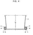
- Figure 4 is a sectional view of a baking tray assembly taken along line IV-IV as shown in FIG. 2;
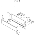
- Figure 5 is an exploded perspective view of the guide seated in the oven compartment, and the baking tray of the bread maker according to a second embodiment of the present invention;
- Figure 6 is an exploded perspective view of the guide seated in the oven compartment, and the baking tray of the bread maker according to a third embodiment of the present invention; and
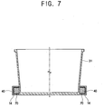
- Figure 7 is a sectional view of a baking tray assembly, taken along line IV-IV as shown in FIG. 2.
-
- Reference will now be made in detail to embodiments of the present invention, examples of which are illustrated in the accompanying drawings, wherein like reference numerals refer to the like elements throughout.
- Figure 1 is a perspective view of a bread maker provided with a baking tray according to an embodiment the present invention. As shown in Figure 1, a bread maker according to an embodiment of the present invention, comprises: a main body 1 provided with an
oven compartment 10; adoor 3 in the front of the main body 1 to rotatably open and close a front opening of theoven compartment 10; and anoperation display panel 2 provided at a side portion of the front of the main body 1 to display an operation state of the main body 1. - Further, towards the upper and lower parts inside the
oven compartment 10 are placed upper and lower kneadingdrums drums lower kneading drums drum 11. - A
baking tray assembly 20, which can be drawn out from theoven compartment 10 that contains kneaded materials needed to make the bread is provided between the upper andlower kneading drums oven compartment 10. - The
baking tray 30 is of a box shape, with a top opening formed by combining stationary andmovable tray members tray holder members 40 connected to opposite ends of the stationary andmovable tray members - At lower parts of opposite sidewalls of the
stationary tray member 31, stationary projections (not shown) to be securely combined with the pair oftray holder members 40 are projected from exterior surfaces of the opposite sidewalls. At lower parts of opposite sidewalls of themovable tray member 33, combiningprojections 34 to be movably combined with the pair oftray holder members 40 are projected from exterior surfaces of the opposite sidewalls. - The pair of
tray holder members 40 are slidingly combined withguides 14 mounted facing each other on opposite inner sidewalls of theoven compartment 10. As parts to be combined with thestationary tray member 31 are stationary projections accommodating parts (not shown) grooved on thetray holder member 40 where the stationary projections of thestationary tray member 31 are inserted. As parts to be combined with themovable tray member 33 areguide grooves 42 formed on thetray holder member 40 where the combiningprojections 34 of themovable tray member 33 are movably inserted. - Upon insertion of the stationary projections of the
stationary tray member 31 in the stationary projections accommodating parts (not shown) of thetray holder member 40, thestationary tray member 31 is securely mounted on thetray holder member 40. Similarly, upon insertion of the combiningprojections 34 of themovable tray member 33 in theguide grooves 42 of thetray holder member 40, themovable tray member 33 is movably mounted on thetray holder member 40. - When the stationary and
movable tray members tray holder member 40 facing each other, thebaking tray 30 which is of a box shape having a top opening to contain the raw materials for the bread is formed. Along the line at which the stationary andmovable tray members slit 21 is formed. - The
tray holder member 40 of thebaking tray assembly 20 is slidingly combined with theguide 14 of theoven compartment 10 so that thebaking tray assembly 20 can be slidably seated inside theoven compartment 10. - Accordingly, the
guides 14 are employed to guide a sliding movement of thetray holder member 40 and form a pair facing each other on the opposite inner sidewalls of theoven compartment 10. - As shown in Figure 3, the
guide 14 comprises: amounting surface 51 mounted on each inner sidewall of theoven compartment 10; aseating surface 52 extending from the lower edge of themounting surface 51 on which the lower surface of thetray holder member 40 is seated; and anupper surface 53 extending from the upper edge of themounting surface 51 and oppositely spaced from theseating surface 52 by a predetermined distance. - The
upper surface 53 of theguide 14 is formed of anarrow part 54 with a width narrower than the transverse width of theseating surface 52; and abroad part 55, which is almost the same width as the width of the transverse width of theseating surface 52. - The
narrow part 54 is almost of the same length as the transverse width c of themovable tray member 33 as shown in Figure 2 in the combination state of theguide 14 and thetray holder member 40. Thebroad part 55 is almost of the same length as the transverse width d (shown in Figure 2) of thestationary tray member 31 as shown in Figure 2. - When the
baking tray assembly 20 is seated in theoven compartment 10 and thetray holder member 40 is slidingly combined with theguide 14, ashock absorber 60 is provided between theguide 14 and thetray holder member 40 to prevent thetray holder member 40 from minute movement in the vertical direction during the winding of the upper andlower kneading drums - The
shock absorber 60 is made of non-metal insulation material with a predetermined elasticity, for example, rubber, silicon or etc. As shown in Figure 3 and 4, according to an embodiment of the invention, the shock absorber 60, comprises: a first shock absorber 61 adhered to the upper surface of thetray holder member 40 in contact with thebroad part 55 of theupper surface 53 of theguide 14; and a second shock absorber 62 adhered to the lower surface of thetray holder member 40. As shown in Figure 5 illustrating a second embodiment of the invention, afirst shock absorber 61a may be adhered to the inner surface of thebroad part 55 of theupper surface 53 of theguide 14, and asecond shock absorber 62a may be adhered to theseating surface 52 of theguide 14. Further, as shown in Figures 6 and 7, non-metal insulation material with a predetermined elasticity may be applied on surfaces which need the shock-absorbing material to provide the surfaces with a benefit similar to the one provided via theshock absorber 60 provided between theguide 14 and thetray holder member 40. - According to this configuration, one end of the mixing bag contained inside the
oven compartment 10 is wound by the upper kneadingdrum 11. Then, the other end of the mixing bag passes through the pair of dough-blockingmembers 13 and theslit 21 formed at the bottom of thebaking tray 30 and then is wound by thelower kneading drum 12. The mixing bag filled with raw materials for bread is reciprocated up and down by the upper andlower kneading drums members 13 and thebaking tray 30. After completing this kneading process, the mixing bag is released from the upper kneadingdrum 11 as thelower kneading drum 12 is the only kneading drum being rotated. Then, the mixing bag passes through the pair of dough-blockingmembers 13 and finally theslit 21 formed at the bottom of thebaking tray 30. Here, when the mixing bag passes through theslit 21 of thebaking tray 30, since the raw materials for the bread contained in the mixing bag cannot pass theslit 21 of thebaking tray 30, the raw materials for the bread are separated from the mixing bag and contained in thebaking tray 30. However, the mixing bag can pass theslit 21 of thebaking tray 30 and is wound by thelower kneading drum 12. Thereafter, the raw materials for the bread contained in thebaking tray 30 are baked by thebaking heater 16. - According to an embodiment of the bread maker of the present invention, while the mixing bag is reciprocated up and down during the kneading process through the
slit 21 formed between the stationary andmovable tray members shock absorber 60 prevents minute movement of thetray holder member 40 in a vertical direction within theguide 14. Therefore, the noise occurring when theguide 14 and thetray holder member 40 are in direct contact can be prevented. - As described above, according to an embodiment of the present invention, the
shock absorber 60 between theguide 14 and thetray holder member 40 prevents minute movement of thetray holder member 40 within theguide 14. Consequently, the noise occurring due to direct contact of theguide 14 andtray holder member 40 can be prevented, thereby, offering a reliable bread maker to a user. - Although a few embodiments of the present invention have been shown and described, it will be appreciated by those skilled in the art that changes may be made in these embodiments without departing from the principles and spirit of the invention, the scope of which is defined in the appended claims and their equivalents.
- Attention is directed to all papers and documents which are filed concurrently with or previous to this specification in connection with this application and which are open to public inspection with this specification, and the contents of all such papers and documents are incorporated herein by reference.
- All of the features disclosed in this specification (including any accompanying claims, abstract and drawings), and/or all of the steps of any method or process so disclosed, may be combined in any combination, except combinations where at least some of such features and/or steps are mutually exclusive.
- Each feature disclosed in this specification (including any accompanying claims, abstract and drawings) may be replaced by alternative features serving the same, equivalent or similar purpose, unless expressly stated otherwise. Thus, unless expressly stated otherwise, each feature disclosed is one example only of a generic series of equivalent or similar features.
- The invention is not restricted to the details of the foregoing embodiment(s). The invention extends to any novel one, or any novel combination, of the features disclosed in this specification (including any accompanying claims, abstract and drawings), or to any novel one, or any novel combination, of the steps of any method or process so disclosed.
Claims (13)
- A bread maker with a main body (1) forming an oven compartment (10), comprising:a pair of tray members (31, 33) provided facing each other to form a slit to pass a mixing bag containing raw materials for the bread;a pair of tray holder members (40) combined with opposite ends of the pair of tray members (31, 33);a pair of guides (14) mounted on inner sidewalls of the oven compartment (10) facing each other to slidably guide the tray holder members (40) by slidingly combining with the tray holder members (40); anda shock absorber (60) introduced between the tray holder members (40) and the guides (14).
- The bread maker according to claim 1, wherein the shock absorber (60) is adhered to one of the tray holder member (40) and the guide (14).
- The bread maker according to claim 1 or claim 2, wherein the pair of guides further comprises:a mounting surface (51) mounted on an inner sidewall of the oven compartment (10);a seating surface (52) extending from the lower edge of the mounting surface (51) to accommodate the lower surface of the tray holder member (40); andan upper surface (53) extending from the upper edge of the mounting surface (51) oppositely spaced from the seating surface (52) by a predetermined distance, the upper surface (53) being formed with a narrow part (54) of a width narrower than the transverse width of the seating surface (52) and a broad part (55) of the same width as the width of transverse width of the seating surface (52).
- The bread maker according to claim 3, wherein the pair of tray members (31, 33) further comprising:a stationary tray member (31) mounted on the tray holder member (40); anda movable tray member (33) movably mounted on the tray holder member (40).
- The bread maker according to any preceding claim, wherein the shock absorber (60) further comprising:a first shock absorber (61) adhered to the upper surface of the tray holder member (4) and in contact with the broad part (55) of the upper surface of the guide (14) ; anda second shock absorber (62) adhered to the lower surface of the tray holder member (40).
- The bread maker according to any one of claims 1-4, wherein the shock absorber (60) further comprising:a first shock absorber (61a) adhered to the inner surface of the broad part (55) of the upper surface of the pair of guides (14); anda second shock absorber (62a) adhered to the seating surface (52) of the pair of guides (14).
- The bread maker according to any preceding claim, wherein the shock absorber (60) includes a non-metal insulation material with elasticity.
- The bread maker according to claim 7, wherein nonmetal insulation material is applied on surfaces which need the shock-absorbing material.
- The bread maker according to claim 4 or any one of claims 5-8 when dependent directly or indirectly on claim 4, further comprising:at least one stationary projection member provided to opposite exterior sidewalls of the stationary tray member (31) to securely combine with the pair of tray holder members (40); andat least one combining projection member (34) provided to opposite exterior sidewalls of the moveable tray member (33) to moveably combine with the pair of tray holder members (40).
- The bread maker according to any preceding claim, wherein the pair of tray holder members (40) are slidingly combined with the pair of guides (14) mounted on inner sidewalls of the oven compartment (10).
- The bread maker according to claim 9 or claim 10 when dependent on claim 9, further comprising:a stationary projection accommodating part grooved on a first end of the pair of tray holder members (40) to be combined with the least one stationary projection; andguide grooves (42) formed on a second end the pair of tray holder members (40) to allow insertion of the at least one combining projection member (34) of the moveable tray member (33).
- The bread maker according to claim 4 or on any one of claims 5-11 when dependent directly or indirectly on claim 4, wherein the narrow part (54) of the upper surface of the guide is of almost same length as the transverse width (c) of the movable tray member (33).
- A bread maker, comprising:a main body (1) forming an oven compartment (10);an upper and a lower kneading drum (11, 12) provided spaced from each other in upper and lower parts of the oven compartment (10) to hold respective ends of a mixing bag and to wind the mixing bag;a pair of tray members (31, 33) disposed between the upper and the lower kneading drums (11, 12) facing each other and forming a slit to allow the mixing bag to pass therethrough;a pair of tray holder members (40) combined with opposite ends of the pair of tray members (31, 33);a pair of guides (14) mounted on inner sidewalls of the oven compartment (10) facing each other to slidably guide the tray holder members (40) by slidingly combining with the tray holder members (40); anda shock absorber (60) introduced between the tray holder members (40) and the guides (14).
Applications Claiming Priority (2)
| Application Number | Priority Date | Filing Date | Title |
|---|---|---|---|
| KR2003029088 | 2003-05-07 | ||
| KR1020030029088A KR20040096216A (en) | 2003-05-07 | 2003-05-07 | Oven for baking bread |
Publications (2)
| Publication Number | Publication Date |
|---|---|
| EP1474982A1 true EP1474982A1 (en) | 2004-11-10 |
| EP1474982B1 EP1474982B1 (en) | 2006-02-01 |
Family
ID=36089215
Family Applications (1)
| Application Number | Title | Priority Date | Filing Date |
|---|---|---|---|
| EP04250851A Expired - Lifetime EP1474982B1 (en) | 2003-05-07 | 2004-02-18 | A bread maker |
Country Status (6)
| Country | Link |
|---|---|
| US (1) | US7267046B2 (en) |
| EP (1) | EP1474982B1 (en) |
| JP (1) | JP3761555B2 (en) |
| KR (1) | KR20040096216A (en) |
| CN (1) | CN1265713C (en) |
| DE (1) | DE602004000366T2 (en) |
Families Citing this family (1)
| Publication number | Priority date | Publication date | Assignee | Title |
|---|---|---|---|---|
| IT1400218B1 (en) * | 2009-03-24 | 2013-05-24 | De Longhi Appliances Srl | APPLIANCES FOR BREAD PRODUCTION |
Citations (1)
| Publication number | Priority date | Publication date | Assignee | Title |
|---|---|---|---|---|
| WO1999025467A1 (en) * | 1997-11-17 | 1999-05-27 | Heden-Team Ag | Automatic baking apparatus and mixbag therefor |
Family Cites Families (7)
| Publication number | Priority date | Publication date | Assignee | Title |
|---|---|---|---|---|
| JP2904298B2 (en) | 1990-03-30 | 1999-06-14 | マツダ株式会社 | Multiplex transmission equipment for vehicles |
| GB2277789B (en) * | 1993-05-07 | 1997-04-09 | Gary John Turner | Vibration isolation platform |
| KR20020053646A (en) | 2000-12-27 | 2002-07-05 | 윤종용 | Bake oven |
| KR100632731B1 (en) * | 2000-12-30 | 2006-10-11 | 삼성전자주식회사 | Baker |
| MX2007008676A (en) | 2005-01-19 | 2007-07-25 | Hoffmann La Roche | 5-aminoindole derivatives. |
| KR100904466B1 (en) | 2007-12-11 | 2009-06-24 | 주식회사 하이닉스반도체 | Termination Circuits for On Die Termination Devices |
| KR100905774B1 (en) | 2009-04-03 | 2009-07-02 | (주)빅하우스 | Water distributor for disinfectant dispenser |
-
2003
- 2003-05-07 KR KR1020030029088A patent/KR20040096216A/en not_active Withdrawn
-
2004
- 2004-02-18 DE DE602004000366T patent/DE602004000366T2/en not_active Expired - Lifetime
- 2004-02-18 EP EP04250851A patent/EP1474982B1/en not_active Expired - Lifetime
- 2004-02-20 CN CNB2004100070072A patent/CN1265713C/en not_active Expired - Fee Related
- 2004-03-22 US US10/805,477 patent/US7267046B2/en not_active Expired - Fee Related
- 2004-03-30 JP JP2004101453A patent/JP3761555B2/en not_active Expired - Fee Related
Patent Citations (1)
| Publication number | Priority date | Publication date | Assignee | Title |
|---|---|---|---|---|
| WO1999025467A1 (en) * | 1997-11-17 | 1999-05-27 | Heden-Team Ag | Automatic baking apparatus and mixbag therefor |
Also Published As
| Publication number | Publication date |
|---|---|
| CN1550147A (en) | 2004-12-01 |
| JP3761555B2 (en) | 2006-03-29 |
| US7267046B2 (en) | 2007-09-11 |
| JP2004329905A (en) | 2004-11-25 |
| KR20040096216A (en) | 2004-11-16 |
| US20040261628A1 (en) | 2004-12-30 |
| DE602004000366D1 (en) | 2006-04-13 |
| EP1474982B1 (en) | 2006-02-01 |
| CN1265713C (en) | 2006-07-26 |
| DE602004000366T2 (en) | 2006-10-12 |
Similar Documents
| Publication | Publication Date | Title |
|---|---|---|
| EP3795494A1 (en) | Slide type lid structure | |
| EP1474982A1 (en) | A bread maker | |
| EP1357504A2 (en) | Bar code reader and bread maker | |
| EP1382254A1 (en) | Improvements in and relating to bread makers | |
| WO2019058541A1 (en) | Receptacle storage structure | |
| CN106885435B (en) | Humidity Adjustment Drawer and Refrigerator | |
| US20040221740A1 (en) | Bread maker | |
| EP1474981A1 (en) | Improvements in and relating to bread makers | |
| EP1474983A1 (en) | Improvements in and relating to bread makers | |
| US20040221728A1 (en) | Bread maker | |
| EP1474987B1 (en) | Bread maker | |
| EP1475019A1 (en) | Bread maker | |
| EP1474978A1 (en) | Bread maker | |
| US20040221732A1 (en) | Bread maker | |
| JPH09206238A (en) | Toilet paper holder | |
| JP5138198B2 (en) | Cup holder device | |
| KR20040096094A (en) | Baking machine | |
| JP2021038658A (en) | Closing device | |
| JP2021076284A (en) | refrigerator | |
| US20040221739A1 (en) | Bread maker | |
| JP2021038658A6 (en) | Switchgear |
Legal Events
| Date | Code | Title | Description |
|---|---|---|---|
| PUAI | Public reference made under article 153(3) epc to a published international application that has entered the european phase |
Free format text: ORIGINAL CODE: 0009012 |
|
| 17P | Request for examination filed |
Effective date: 20040218 |
|
| AK | Designated contracting states |
Kind code of ref document: A1 Designated state(s): AT BE BG CH CY CZ DE DK EE ES FI FR GB GR HU IE IT LI LU MC NL PT RO SE SI SK TR |
|
| AX | Request for extension of the european patent |
Extension state: AL LT LV MK |
|
| GRAP | Despatch of communication of intention to grant a patent |
Free format text: ORIGINAL CODE: EPIDOSNIGR1 |
|
| GRAS | Grant fee paid |
Free format text: ORIGINAL CODE: EPIDOSNIGR3 |
|
| AKX | Designation fees paid |
Designated state(s): DE FR GB SE |
|
| GRAA | (expected) grant |
Free format text: ORIGINAL CODE: 0009210 |
|
| AK | Designated contracting states |
Kind code of ref document: B1 Designated state(s): DE FR GB SE |
|
| REG | Reference to a national code |
Ref country code: GB Ref legal event code: FG4D |
|
| REF | Corresponds to: |
Ref document number: 602004000366 Country of ref document: DE Date of ref document: 20060413 Kind code of ref document: P |
|
| REG | Reference to a national code |
Ref country code: SE Ref legal event code: TRGR |
|
| ET | Fr: translation filed | ||
| PLBE | No opposition filed within time limit |
Free format text: ORIGINAL CODE: 0009261 |
|
| STAA | Information on the status of an ep patent application or granted ep patent |
Free format text: STATUS: NO OPPOSITION FILED WITHIN TIME LIMIT |
|
| 26N | No opposition filed |
Effective date: 20061103 |
|
| PGFP | Annual fee paid to national office [announced via postgrant information from national office to epo] |
Ref country code: FR Payment date: 20110218 Year of fee payment: 8 Ref country code: SE Payment date: 20110211 Year of fee payment: 8 Ref country code: DE Payment date: 20110216 Year of fee payment: 8 |
|
| PGFP | Annual fee paid to national office [announced via postgrant information from national office to epo] |
Ref country code: GB Payment date: 20110216 Year of fee payment: 8 |
|
| GBPC | Gb: european patent ceased through non-payment of renewal fee |
Effective date: 20120218 |
|
| PG25 | Lapsed in a contracting state [announced via postgrant information from national office to epo] |
Ref country code: SE Free format text: LAPSE BECAUSE OF NON-PAYMENT OF DUE FEES Effective date: 20120219 |
|
| REG | Reference to a national code |
Ref country code: FR Ref legal event code: ST Effective date: 20121031 |
|
| REG | Reference to a national code |
Ref country code: DE Ref legal event code: R119 Ref document number: 602004000366 Country of ref document: DE Effective date: 20120901 |
|
| PG25 | Lapsed in a contracting state [announced via postgrant information from national office to epo] |
Ref country code: GB Free format text: LAPSE BECAUSE OF NON-PAYMENT OF DUE FEES Effective date: 20120218 Ref country code: FR Free format text: LAPSE BECAUSE OF NON-PAYMENT OF DUE FEES Effective date: 20120229 |
|
| PG25 | Lapsed in a contracting state [announced via postgrant information from national office to epo] |
Ref country code: DE Free format text: LAPSE BECAUSE OF NON-PAYMENT OF DUE FEES Effective date: 20120901 |